kis beam technology load cells and weighing modules
TRANSCRIPT

KIS Beam TechnologyMarket Solutions
SMART SOLUT IONS FORDEMANDING INDUSTR IES
The KIS Double Cantilever Advantage
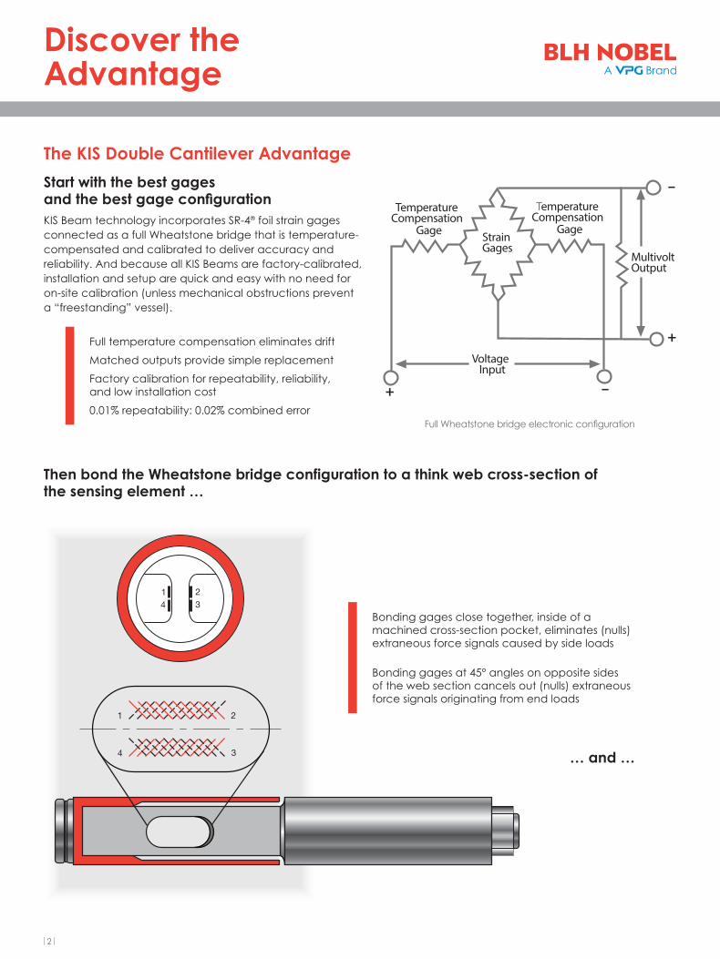
Start with the best gages and the best gage configurationKIS Beam technology incorporates SR-4® foil strain gages connected as a full Wheatstone bridge that is temperature-compensated and calibrated to deliver accuracy and reliability. And because all KIS Beams are factory-calibrated, installation and setup are quick and easy with no need for on-site calibration (unless mechanical obstructions prevent a “freestanding” vessel).
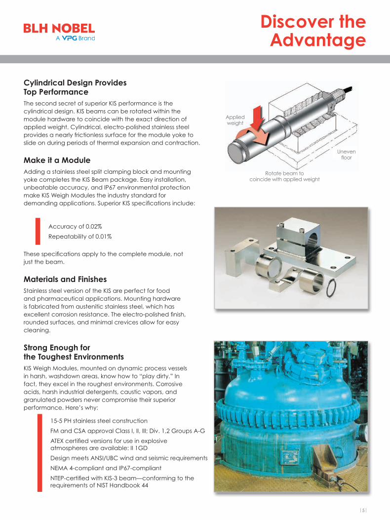
Then bond the Wheatstone bridge configuration to a think web cross-section of the sensing element …
Full temperature compensation eliminates drift
Matched outputs provide simple replacement
Factory calibration for repeatability, reliability, and low installation cost
0.01% repeatability: 0.02% combined error
1 234
4
1
3
2
+Voltage Input
TemperatureCompensation
Gage
TemperatureCompensation
Gage
+ –
–
MultivoltOutput
StrainGages
… and …
Full Wheatstone bridge electronic configuration
Bonding gages close together, inside of a machined cross-section pocket, eliminates (nulls) extraneous force signals caused by side loads
Bonding gages at 45° angles on opposite sides of the web section cancels out (nulls) extraneous force signals originating from end loads
|2|
Discover the Advantage

KIS Beam design adds a second or “double” cantilever sleeve over the actual load beam.
This locates the load force application point directly above the gages. Placing the Wheatstone bridge gage network beneath the applied load results in significant performance advantages:
… place the load right over the gages
Side load force sensitivity is virtually eliminated
Moment stresses upon the gages are “zero”
Bending stress at the mounting base is reduced by 50%
Shears stresses remain constant
Moving or sliding the load point produces negligible effect on output
The measurement signal represents the only true applied force
Movable load point
Force applied directly to the sleeve (cutaway) over the gage pocket area
Double Cantilever Shear Beam Single Cantilever Bending Beam
Cla
mp
ing
blo
ck
Bending force Upturning force
Applied weight(to cantilever sleeve)
Zero bending forcesensed by gages
Zero distortion of true force signal
Bending force
Applied weight
Some distortion of true force signal
Bending forcesensed by gages
|3|
Discover the Advantage

Moving Load
Force measurement in materials testing
Standard tank weighing
Vibration from agitation Thermal expansion Twisting moment caused by agitator
Orienting the load cells towards the center gives a self-locking design that
counteracts movement.
|4|
Discover the Advantage
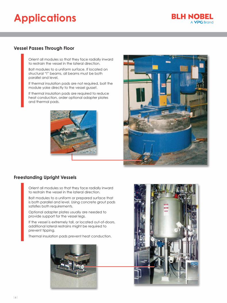
Cylindrical Design Provides Top PerformanceThe second secret of superior KIS performance is the cylindrical design. KIS beams can be rotated within the module hardware to coincide with the exact direction of applied weight. Cylindrical, electro-polished stainless steel provides a nearly frictionless surface for the module yoke to slide on during periods of thermal expansion and contraction.
Make it a ModuleAdding a stainless steel split clamping block and mounting yoke completes the KIS Beam package. Easy installation, unbeatable accuracy, and IP67 environmental protection make KIS Weigh Modules the industry standard for demanding applications. Superior KIS specifications include:
These specifications apply to the complete module, not just the beam.
Materials and FinishesStainless steel version of the KIS are perfect for food and pharmaceutical applications. Mounting hardware is fabricated from austenitic stainless steel, which has excellent corrosion resistance. The electro-polished finish, rounded surfaces, and minimal crevices allow for easy cleaning.
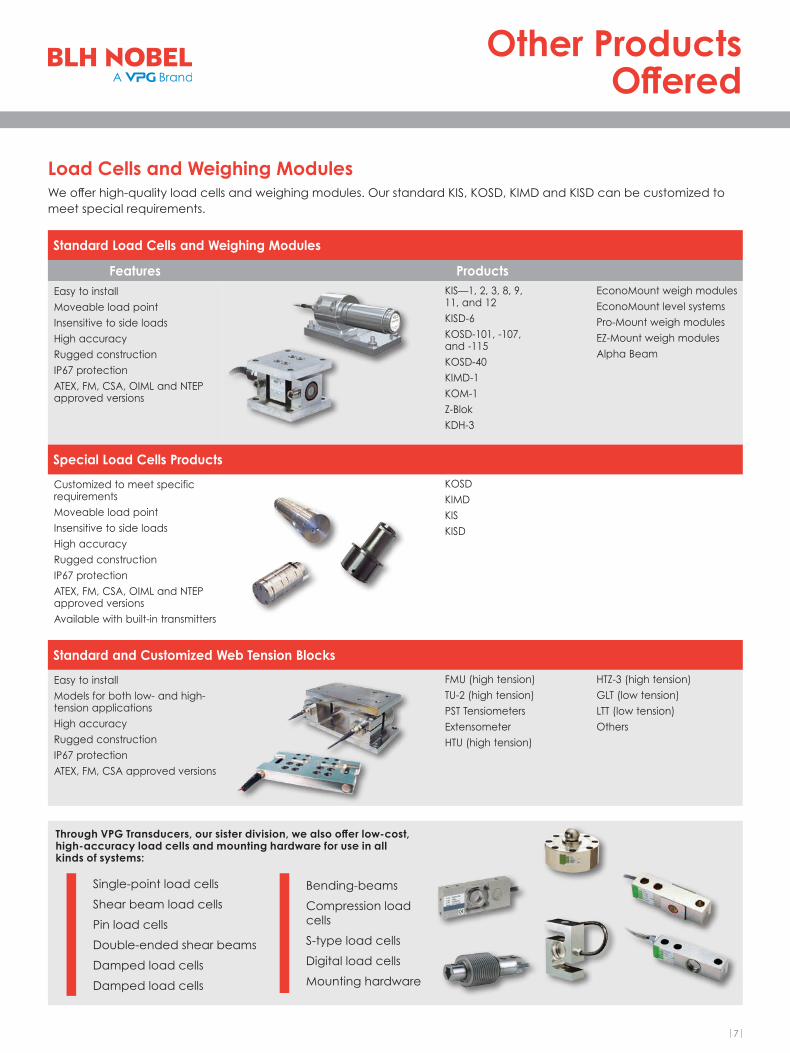
Strong Enough for the Toughest EnvironmentsKIS Weigh Modules, mounted on dynamic process vessels in harsh, washdown areas, know how to “play dirty.” In fact, they excel in the roughest environments. Corrosive acids, harsh industrial detergents, caustic vapors, and granulated powders never compromise their superior performance. Here’s why:
Accuracy of 0.02%
Repeatability of 0.01%
15-5 PH stainless steel construction
FM and CSA approval Class I, II, III; Div. 1,2 Groups A-G
ATEX certified versions for use in explosive atmospheres are available: II 1GD
Design meets ANSI/UBC wind and seismic requirements
NEMA 4-compliant and IP67-compliant
NTEP-certified with KIS-3 beam—conforming to the requirements of NIST Handbook 44
Applied weight
Rotate beam to coincide with applied weight
Uneven floor
|5|
Discover the Advantage
Vessel Passes Through Floor
Freestanding Upright Vessels
Orient all modules so that they face radially inward to restrain the vessel in the lateral direction.
Bolt modules to a uniform surface. If located on structural “I” beams, all beams must be both parallel and level.
If thermal insulation pads are not required, bolt the module yoke directly to the vessel gusset.
If thermal insulation pads are required to reduce heat conduction, order optional adapter plates and thermal pads.
Orient all modules so that they face radially inward to restrain the vessel in the lateral direction.
Bolt modules to a uniform or prepared surface that is both parallel and level. Using concrete grout pads satisfies both requirements.
Optional adapter plates usually are needed to provide support for the vessel legs.
If the vessel is extremely tall, or located out-of-doors, additional lateral restrains might be required to prevent tipping.
Thermal insulation pads prevent heat conduction.
|6|
Applications
Load Cells and Weighing ModulesWe offer high-quality load cells and weighing modules. Our standard KIS, KOSD, KIMD and KISD can be customized to meet special requirements.
Standard Load Cells and Weighing Modules
Features ProductsEasy to installMoveable load pointInsensitive to side loadsHigh accuracyRugged constructionIP67 protectionATEX, FM, CSA, OIML and NTEP approved versions
KIS—1, 2, 3, 8, 9, 11, and 12KISD-6KOSD-101, -107, and -115KOSD-40KIMD-1KOM-1Z-BlokKDH-3
EconoMount weigh modulesEconoMount level systemsPro-Mount weigh modulesEZ-Mount weigh modulesAlpha Beam
Special Load Cells Products
Customized to meet specific requirementsMoveable load pointInsensitive to side loadsHigh accuracyRugged constructionIP67 protectionATEX, FM, CSA, OIML and NTEP approved versionsAvailable with built-in transmitters
KOSDKIMDKISKISD
Standard and Customized Web Tension Blocks
Easy to installModels for both low- and high-tension applicationsHigh accuracyRugged constructionIP67 protectionATEX, FM, CSA approved versions
FMU (high tension)TU-2 (high tension)PST TensiometersExtensometerHTU (high tension)
HTZ-3 (high tension)GLT (low tension)LTT (low tension)Others
Through VPG Transducers, our sister division, we also offer low-cost, high-accuracy load cells and mounting hardware for use in all kinds of systems:
Single-point load cells
Shear beam load cells
Pin load cells
Double-ended shear beams
Damped load cells
Damped load cells
Bending-beams
Compression load cells
S-type load cells
Digital load cells
Mounting hardware
|7|
Other ProductsOffered

Contact
SMART SOLUT IONS FORDEMANDING INDUSTR IES
DISCLAIMER: ALL PRODUCTS, PRODUCT SPECIFICATIONS AND DATA ARE SUBJECT TO CHANGE WITHOUT NOTICE. Vishay Precision Group, Inc., its affiliates, agents, and employees, and all persons acting on its or their behalf (collectively, “VPG”), disclaim any and all liability for any errors, inaccuracies or incompleteness contained herein or in any other disclosure relating to any product. The product specifications do not expand or otherwise modify VPG’s terms and conditions of purchase, including but not limited to, the warranty expressed therein. VPG makes no warranty, representation or guarantee other than as set forth in the terms and conditions of purchase. To the maximum extent permitted by applicable law, VPG disclaims (i) any and all liability arising out of the application or use of any product, (ii) any and all liability, including without limitation special, consequential or incidental damages, and (iii) any and all implied warranties, including warranties of fitness for particular purpose, non-infringement and merchantability. Information provided in datasheets and/or specifications may vary from actual results in different applications and performance may vary over time. Statements regarding the suitability of products for certain types of applications are based on VPG’s knowledge of typical requirements that are often placed on VPG products. It is the customer’s responsibility to validate that a particular product with the properties described in the product specification is suitable for use in a particular application. You should ensure you have the current version of the relevant information by contacting VPG prior to performing installation or use of the product, such as on our website at vpgsensors.com. No license, express, implied, or otherwise, to any intellectual property rights is granted by this document, or by any conduct of VPG. The products shown herein are not designed for use in life-saving or life-sustaining applications unless otherwise expressly indicated. Customers using or selling VPG products not expressly indicated for use in such applications do so entirely at their own risk and agree to fully indemnify VPG for any damages arising or resulting from such use or sale. Please contact authorized VPG personnel to obtain written terms and conditions regarding products designed for such applications. Product names and markings noted herein may be trademarks of their respective owners.
VPW-PL0449-1410
blhnobel.com