king of tone guitar pedal modeling with …kaichieh/kingoftone.pdfp#1! king of tone guitar pedal...
TRANSCRIPT

p-‐1
KING OF TONE GUITAR PEDAL MODELING WITH NODAL ANALYSIS & TABLE PRECONSTRUCTION METHOD
Kai-Chieh Huang Adviser: Julius O. Smith, Jonathan Abel, David Berners
Center for Computer Research in Music & Acoustics Stanford University, Stanford, CA
ABSTRACT This project explores the methods of modeling gui-‐tar overdrive/distortion pedal with nonlinear components by analyzing the handmade Analog Man King Of Tone overdrive pedal. The schematics of the King Of Tone pedal is studied and divided into three stages: the gain driving stage, over-‐drive-‐clipping stage, and tone control stage. In this paper, the gain driving stage of the circuit is exam-‐ined using nodal analysis to solve for the transfer function and digitized through bilinear transform. Then, a table preconstruction method is proposed to solve for the output voltage at the over-‐drive-‐clipping stage. Finally, a Python simulation of this digital circuit model is implemented and its output at the second stage is then compared to the result derived in LTSpice. The research into the third stage of the circuit will be carried out in the future work.
1. INTRODUCTION
The guitar overdrive and distortion effects have been used extensively in the rock and roll music since the early sixties. Since then, many overdrive and distortion pedals have been developed by music instrument companies such as Boss, Ibanez, and Marshall, just to name a few. During the early years, overdrive and dis-‐tortion effects are mainly generated by overdriving the vacuum tubes, particularly triodes, to create a warm distortion tone [1] and this sound quality is generally praised to be superior. These types of distortion pedal or amplifier require, however, a hefty fee as they be-‐come harder to obtain in nowadays. Over the years, some overdrive circuits have evolved to adopt other nonlinear elements such as diodes and transistors as an alternate clipping method in order to achieve lower cost. With proper design, these circuits could sound similar to the classic tube distortion tone. The price of the analog pedals described formally can still be a burden to amateur musicians who are seeking classic tube distortion tone. Luckily, due to the advance in computational technology through out the
years, many researches have been carried out to ex-‐plore the procedure of designing a distortion algorithm that models a specific analog pedal of interest with sat-‐isfied accuracy, as digital world has several advantages over the analog. First of all, the fee of digital effects are much more amiable to customers compare to analog pedals thanks to the low software development cost. Besides a good deal of price, digital effects are also eas-‐ier to distribute through the Internet and is effortless to make copies to keep up the supply. In addition, digital effects can be modified or updated easily, unlike analog pedals. These advantages make designing a digital overdrive/distortion effect model a good topic of re-‐search. The King Of Tone overdrive/distortion pedal [2] is a handmade pedal produced by the Analog Man and it is famous for it’s tube like overdrive, which preserves the original guitar tone and dynamic while distorting the signal. Owing to its handmade nature, to obtain a new pedal from Analog Man, it requires a long waiting pe-‐riod, typically a 1-‐year waiting list. Since the supply is much lower than demand, the price of the pedal is over 400 dollars. This pedal undoubtedly embodies the con-‐straint of analog pedals. Hence, it is definitely beneficial to develop a digital model of this pedal while exploring the means of analyzing and modeling the nonlinear circuit. In the following, an introduction to the basic tools of analyzing and modeling the circuit is given first. Then, the circuit analysis of the gain driving stage and over-‐drive-‐clipping stage is presented. Finally, the imple-‐mentation of Python simulation and the modeling re-‐sults are discussed.
2. BASIC ANALYSIS TOOLS
2.1 Op-‐Amp Nodal Analysis
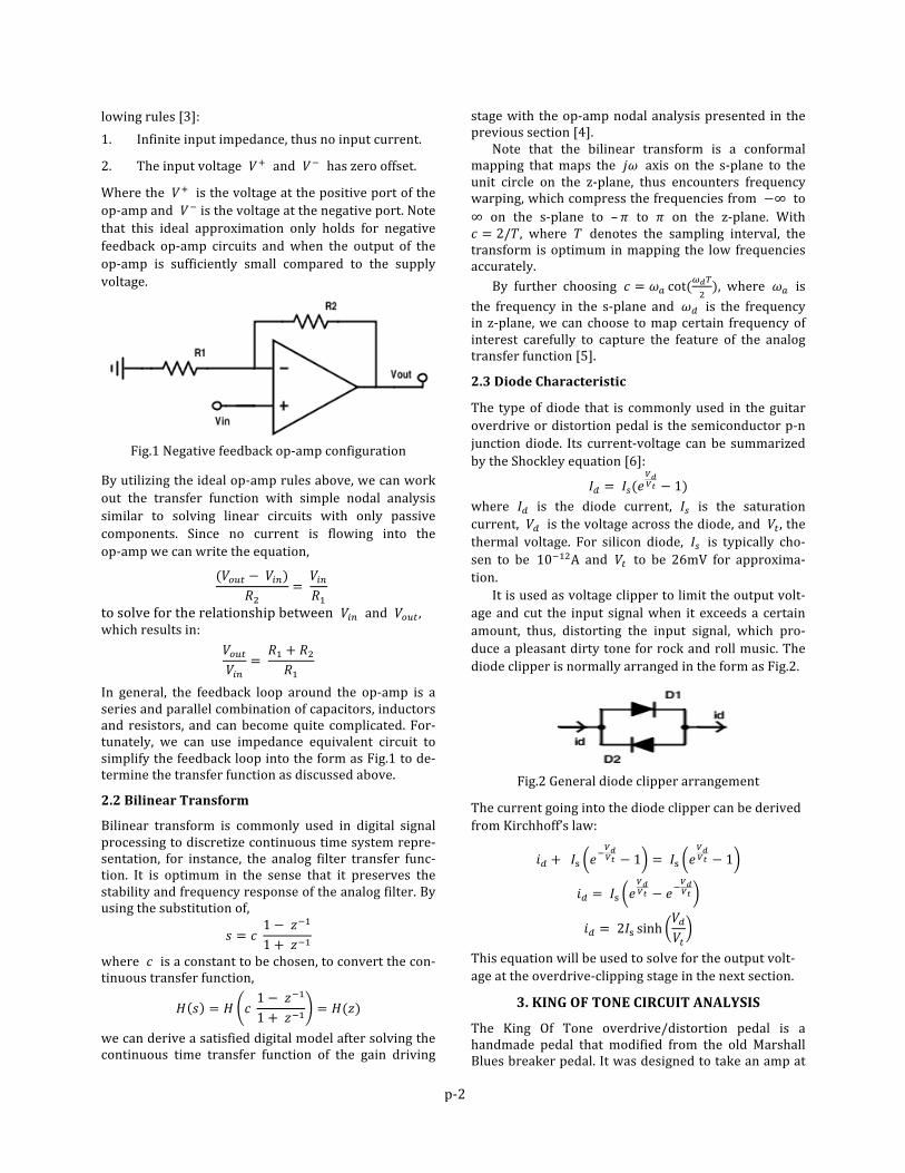
A circuit configuration commonly used in the overdrive and distortion pedals is the negative feedback op-‐amp design as Fig.1. This configuration is often used to design a certain driving filter that boost the selected frequency band of the input signal before going into the clipping stage. To solve for the transfer function of the driving filter, we can use the principle of ideal op-‐amp approximation, which can be summarized by the fol-‐
p-‐2
lowing rules [3]: 1. Infinite input impedance, thus no input current.
2. The input voltage 𝑉! and 𝑉! has zero offset.
Where the 𝑉! is the voltage at the positive port of the op-‐amp and 𝑉! is the voltage at the negative port. Note that this ideal approximation only holds for negative feedback op-‐amp circuits and when the output of the op-‐amp is sufficiently small compared to the supply voltage.
Fig.1 Negative feedback op-‐amp configuration
By utilizing the ideal op-‐amp rules above, we can work out the transfer function with simple nodal analysis similar to solving linear circuits with only passive components. Since no current is flowing into the op-‐amp we can write the equation,
(𝑉!"# − 𝑉!")
𝑅!= 𝑉!"𝑅!
to solve for the relationship between 𝑉!" and 𝑉!"# , which results in:
𝑉!"#𝑉!"
= 𝑅! + 𝑅!𝑅!
In general, the feedback loop around the op-‐amp is a series and parallel combination of capacitors, inductors and resistors, and can become quite complicated. For-‐tunately, we can use impedance equivalent circuit to simplify the feedback loop into the form as Fig.1 to de-‐termine the transfer function as discussed above.
2.2 Bilinear Transform
Bilinear transform is commonly used in digital signal processing to discretize continuous time system repre-‐sentation, for instance, the analog filter transfer func-‐tion. It is optimum in the sense that it preserves the stability and frequency response of the analog filter. By using the substitution of,
𝑠 = 𝑐 1 − 𝑧!!
1 + 𝑧!!
where 𝑐 is a constant to be chosen, to convert the con-‐tinuous transfer function,
𝐻 𝑠 = 𝐻 𝑐 1 − 𝑧!!
1 + 𝑧!! = 𝐻(𝑧)
we can derive a satisfied digital model after solving the continuous time transfer function of the gain driving
stage with the op-‐amp nodal analysis presented in the previous section [4]. Note that the bilinear transform is a conformal mapping that maps the 𝑗𝜔 axis on the s-‐plane to the unit circle on the z-‐plane, thus encounters frequency warping, which compress the frequencies from −∞ to ∞ on the s-‐plane to –𝜋 to 𝜋 on the z-‐plane. With 𝑐 = 2/𝑇, where 𝑇 denotes the sampling interval, the transform is optimum in mapping the low frequencies accurately. By further choosing 𝑐 = 𝜔! cot(
!!!!), where 𝜔! is
the frequency in the s-‐plane and 𝜔! is the frequency in z-‐plane, we can choose to map certain frequency of interest carefully to capture the feature of the analog transfer function [5].
2.3 Diode Characteristic
The type of diode that is commonly used in the guitar overdrive or distortion pedal is the semiconductor p-‐n junction diode. Its current-‐voltage can be summarized by the Shockley equation [6]:
𝐼! = 𝐼!(𝑒!!!! − 1)
where 𝐼! is the diode current, 𝐼! is the saturation current, 𝑉! is the voltage across the diode, and 𝑉! , the thermal voltage. For silicon diode, 𝐼! is typically cho-‐sen to be 10!!"A and 𝑉! to be 26mV for approxima-‐tion. It is used as voltage clipper to limit the output volt-‐age and cut the input signal when it exceeds a certain amount, thus, distorting the input signal, which pro-‐duce a pleasant dirty tone for rock and roll music. The diode clipper is normally arranged in the form as Fig.2.
Fig.2 General diode clipper arrangement
The current going into the diode clipper can be derived from Kirchhoff’s law:
𝑖! + 𝐼! 𝑒!!!!! − 1 = 𝐼! 𝑒
!!!! − 1
𝑖! = 𝐼! 𝑒!!!! − 𝑒!
!!!!
𝑖! = 2𝐼! sinh𝑉!𝑉!
This equation will be used to solve for the output volt-‐age at the overdrive-‐clipping stage in the next section.
3. KING OF TONE CIRCUIT ANALYSIS
The King Of Tone overdrive/distortion pedal is a handmade pedal that modified from the old Marshall Blues breaker pedal. It was designed to take an amp at

p-‐3
reasonable settings, and make it sound like it would sound if it were naturally driven to pure, smooth, tube distortion, without using any tubes. Much like other overdrive or distortion pedals, the King Of Tone circuit can be divided into three stages: the gain driving stage, overdrive-‐clipping stage, and tone control stage. The schematic of the King Of Tone overdrive/distortion pedal is shown in Fig.3.
Fig.3 King Of Tone Schematic It contains four Dip Switches for four different effect levels from overdrive to distortion. In this project, the circuit with the Dip Switch 1 on is analyzed and mod-‐eled. With the analysis tools discussed previously, the first two stages of the King Of Tone circuit are exam-‐ined in detail in the ensuing sections.
3.1 Gain Driving Stage
The first stage of an overdrive/distortion circuit is usu-‐ally an analog filter, which drives the certain frequency range of the input signal with controllable gain. The gain driving stage of the King Of Tone pedal is pre-‐sented in Fig.4.
Fig.4 Gain driving stage circuit
Since the impedance at the output port of an op-‐amp is ideally infinitely small, we can assume it’s output is not affected by the circuit it drives. As a result, we can ba-‐sically break apart all the stages and analyze each building part separately. To analyze the gain driving circuit, we can utilize
the op-‐amp nodal analyze to solve for it’s transfer func-‐tion. By using the impedance equivalent circuit to sim-‐plify the circuit in the form as discussed in section 2.1 and computing all the impedance in s-‐plane where the impedance of capacitance becomes 1/sC, we obtain the equivalent circuit as follows:
Where,
𝑅! = (1𝑠𝐶!
+ 𝑅!)//(1𝑠𝐶!
+ 𝑅!)
𝑅! = (1𝑠𝐶!
)//(𝑅! + 𝑅!"#$% ∗ t)
𝑉!" = 𝑉!"#$% ∗ [𝑅!/(1𝑠𝐶!
+ 𝑅!)]
and // denotes the parallel operation for impedance, and t is the driving ratio from 0 to 1 which change the value of 𝑅!"#$% and hence controls the driving gain. Since the bias voltage is only providing a DC offset for the circuit, we can neglect it when deriving the transfer function. With the op-‐amp nodal analysis result from section 2.1, we can plug in the equation:
𝑉!"#𝑉!"
= 𝑅! + 𝑅!𝑅!
to obtain the transfer function which is a fourth order analog filter with the form of:
𝑏!𝑠! + 𝑏!𝑠! + 𝑏!𝑠! + 𝑏!𝑠 + 𝑏!𝑎!𝑠! + 𝑎!𝑠! + 𝑎!𝑠! + 𝑎!𝑠 + 𝑎!
where,
𝑎! = 𝑅!𝐶!𝐶!𝐶!𝐶!𝑅!𝑅!𝑅!8 𝑎! = 𝐶!𝐶!𝐶!𝑅!𝑅!𝑅! + 𝑅!𝐶!𝐶!𝐶!𝑅!𝑅! + 𝑅!𝐶!𝐶!𝐶!𝑅!𝑅! +𝑅!𝐶!𝐶!𝐶!𝑅!𝑅!
𝑎! = 𝐶!𝐶!𝑅!𝑅! + 𝐶!𝐶!𝑅!𝑅! + 𝑅!𝐶!𝐶!𝑅! + 𝐶!𝐶!𝑅!𝑅! +𝑅!𝐶!𝐶!𝑅! + 𝑅!𝐶!𝐶!𝑅!
𝑎! = 𝐶!𝑅! + 𝐶!𝑅! + 𝐶!𝑅! + 𝑅!𝐶!
𝑎! = 1, 𝑏! = 𝑎!, 𝑏! = 0
𝑏! = 𝐶!𝐶!𝐶!𝑅!𝑅!𝑅! + 𝑅!𝐶!𝐶!𝐶!𝑅!𝑅! + 𝑅!𝐶!𝐶!𝐶!𝑅!𝑅! + 𝑅!𝐶!𝐶!𝐶!𝑅!𝑅! + 𝑅!𝐶!𝐶!𝐶!𝑅!𝑅!
𝑏! = 𝐶!𝐶!𝑅!𝑅! + 𝐶!𝐶!𝑅!𝑅! + 𝑅!𝐶!𝐶!𝑅! + 𝑅!𝐶!𝐶!𝑅! + 𝑅!𝐶!𝐶!𝑅!
𝑏! = 𝐶!𝑅!
With the transfer function of the analog filter, we can

p-‐4
further digitize it through bilinear transform.
3.2 Overdrive Clipping Stage
Several approaches have been researched to address the nonlinear elements, especially diodes, in the circuit. These approaches include incremental model for diode, Newton’s iteration method [7], or wave digital filter [8]. Using the incremental model for diode to linearize it at a particular voltage across the diode and use the New-‐ton’s iteration method to find the converged voltage is a straightforward way of finding the output voltage. Nonetheless, the iteration number required for con-‐vergence increase rapidly as the frequency of the signal gets higher. The computation load due to the iterations can be overwhelming since each output sample de-‐pends on a certain amount of iterations. Fortunately, for certain circuit configuration such as the overdrive clipping stage of the King Of Tone circuit, we can use a different method to solve for the nonlinear output and avoid the heavy computational load encountered with Newton’s iteration. The overdrive-‐clipping circuit is presented in Fig.5. Note that the input voltage of this stage is the output voltage from the gain driving stage.
Fig.5 Overdrive clipping stage circuit
In this section, a table preconstruction method is pro-‐posed to model the King Of Tone overdrive-‐clipping stage accurately. Since there is a resistor and capacitor between the input voltage of this stage and the negative terminal of the op-‐amp, we can calculate the current going into the negative feedback circuit. By utilizing this fact, it is feasible for us to pre-‐construct a cur-‐rent-‐voltage table, where the current in the table is the current going into the negative feedback circuit and the voltage is the voltage across the negative feedback cir-‐cuit, which is also the output voltage. For instance, if the voltage across the two-‐diode clipper is 𝑉! , the current through 𝑅!!, denoted 𝑖!, is 2𝐼! sinh
!!!!!
as derived in section 2.3. With this infor-‐mation, we can find the voltage across the negative
feedback, denoted 𝑉!"# as,
𝑉!"# = 𝑅!! ∗ 2𝐼! sinh!!!!!
+ 𝑉!
Furthermore, we can calculate the current through 𝑅!", denoted 𝑖!, as 𝑉!"#/𝑅!". With 𝑖! and 𝑖!, we can find the total current going into the negative feedback cir-‐cuit as,
𝑖!"!#$ = 𝑖! + 𝑖! = 2𝐼! sinh!!!!!
+ !!"#!!"
where 𝑉!"# is also a function of 𝑉! . As a consequence, given a 𝑉! , we can find a unique pair of 𝑖!"!#$ and 𝑉!"# . By applying a range of 𝑉! , for example, -‐2 to 2 with 0.001 sampling interval, we can pre-‐construct a table of the total current into the negative feedback loop versus the output voltage. With the pre-‐constructed cur-‐rent-‐voltage table, we only need to compute the current going through 𝑅! and 𝐶!, which is total current going into the feedback loop. Then, we can use the table di-‐rectly to find the corresponded output voltage or in-‐terpolate when necessary. By adopting the table pre-‐construction method, the computation load is reduced significantly as compared to using Newton’s iteration.
4. IMPLEMENTATION & RESULTS
A Python simulation is implemented to design a digital King Of Tone overdrive/distortion effect with the tech-‐niques described in this paper. The quality of the model is discussed through comparing its output to the results derived in LTSpice. The circuit built in LTSpice is con-‐structed exactly as the King Of Tone schematic [9]. In the gain driving stage, the magnitude response of the gain-‐driving filter is examined. Then, the direct output signal at the overdrive-‐clipping stage of the digital model is scrutinized to see if it matches up with the distorted output of the original King Of Tone circuit.
4.1 Gain Driving Stage results
In python implementation, first, an analog filter with the coefficients derived through ideal op-‐amp nodal analysis is designed. Its magnitude response is then compared to the magnitude response we obtained in LTSpice. The magnitude response data is exported from LTSpice and imported into Python to plot with the magnitude response of the analog filter we designed. The magnitude response comparison of LTSpice versus our analog filter model is presented in Fig.6 in the next page, where the black dotted line is the magnitude re-‐sponse of the result derived in LTSpice and the red line from our analog filter model. As we can see in the plot, these two magnitude responses match well and prove that the ideal op-‐amp nodal analysis is correct. When we adjust the drive control resistor, the peak of the magnitude response is moved up and down to provide different gain level. With the analog transfer function, we can digitize

p-‐5
it through bilinear transform as discussed previously. For accuracy, we will use the bilinear transform with c = 𝜔! cot(
!!!!) where the target frequency is set to be
at the peak of the magnitude response, which is 4194 Hz. The magnitude response of the digitized filter compared to the analog filter model is as in Fig.7.
Fig.6 Magnitude Response: LTSpice vs. Analog
Fig.7 Magnitude Response: Analog vs. Digital
The result appears, to be quite similar to its analog counterpart with only a mismatch in the high fre-‐quencies around the Nyquits frequency. This is, how-‐ever, due to the frequency warping caused by the bi-‐linear transform. The digital version of the gain driving stage still preserves the characteristics of the genuine circuit, which boost the midrange frequencies— -‐frequencies neighboring the peak frequency 4194 Hz—of the input signal with a controllable gain.
4.2 Overdrive Clipping Stage results
As proposed formally, to solve for the output voltage of a circuit consist of nonlinear elements, the table pre-‐construction method is used. Given 𝑉! in the range of -‐1.10 to 1.10 with 0.00005 sampling interval, the plot of the current-‐voltage table we pre-‐constructed is pre-‐sented here in Fig.8:
Fig.8: Pre-‐constructed Itotal vs. Vout table
With this table, the output of the overdrive-‐clipping stage is computed by sending a 600 Hz sine wave as input signal. The plot of the output signal is as Fig.9 be-‐low:
Fig.9 Distorted sine wave through the model
which is similar to the output we obtained in LTSpice shown below in Fig.10:
Fig.10 Distorted sine wave from LTSpice
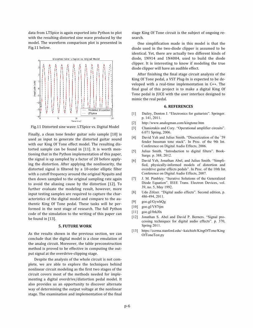
It is similar in the sense that both the distortions pre-‐serve the peaks of the original sine wave and only mod-‐ify its shape besides the peak. The distorted sine wave
p-‐6
data from LTSpice is again exported into Python to plot with the resulting distorted sine wave produced by the model. The waveform comparison plot is presented in Fig.11 below.
Fig.11 Distorted sine wave: LTSpice vs. Digital Model
Finally, a clean tone fender guitar solo sample [10] is used as input to generate the distorted guitar sound with our King Of Tone effect model. The resulting dis-‐torted sample can be found in [11]. It is worth men-‐tioning that in the Python implementation of this paper, the signal is up sampled by a factor of 20 before apply-‐ing the distortion. After applying the nonlinearity, the distorted signal is filtered by a 10-‐order elliptic filter with a cutoff frequency around the original Nyquits and then down sampled to the original sampling rate again to avoid the aliasing cause by the distortion [12]. To further evaluate the modeling result, however, more input testing samples are required to capture the char-‐acteristics of the digital model and compare to the au-‐thentic King Of Tone pedal. These tasks will be per-‐formed in the next stage of research. The full Python code of the simulation to the writing of this paper can be found in [13].
5. FUTURE WORK
As the results shown in the previous section, we can conclude that the digital model is a close emulation of the analog circuit. Moreover, the table preconstruction method is proved to be effective in computing the out-‐put signal at the overdrive-‐clipping stage. Despite the analysis of the whole circuit is not com-‐plete, we are able to explore the techniques behind nonlinear circuit modeling as the first two stages of the circuit covers most of the methods needed for imple-‐menting a digital overdrive/distortion pedal model. It also provides us an opportunity to discover alternate way of determining the output voltage at the nonlinear stage. The examination and implementation of the final
stage King Of Tone circuit is the subject of ongoing re-‐search. One simplification made in this model is that the diode used in the two-‐diode clipper is assumed to be identical. Yet, there are actually two different kinds of diode, 1N914 and 1N4004, used to build the diode clipper. It is interesting to know if modeling the true diode clipper will have an audible effect. After finishing the final stage circuit analysis of the King Of Tone pedal, a VST Plug-‐In is expected to be de-‐veloped with a real-‐time implementation in C++. The final goal of this project is to make a digital King Of Tone pedal in JUCE with the user interface designed to mimic the real pedal.
6. REFERENCES
[1] Dailey, Denton J. “Electronics for guitarists”. Springer. p. 141, 2011.
[2] http://www.analogman.com/kingtone.htm [3] Chaniotakis and Cory. “Operational amplifier circuits”.
6.071 Spring, 2006. [4] David Yeh and Julius Smith. “Discretization of the ’59
fender bassman tone stack”. In Proc. of the 9th Int. Conference on Digital Audio Effects, 2006.
[5] Julius Smith. “Introduction to digital filters”. Book-Surge. p. 388, 2012.
[6] David Yeh, Jonathan Abel, and Julius Smith. “Simpli-fied, physically-informed models of distortion and overdrive guitar effects pedals”. In Proc. of the 10th Int. Conference on Digital Audio Effects, 2007.
[7] J. M. Pimbley. “Iterative Solutions of the Generalized Diode Equation”. IEEE Trans. Electron Devices, vol. 39, no. 5, May 1992.
[8] Udo Zölzer. “Digital audio effects”. Second edition, p. 486-494, 2011.
[9] goo.gl/GywhQg [10] goo.gl/V87tjm [11] goo.gl/0rkJ0s [12] Jonathan S. Abel and David P. Berners. “Signal pro-
cessing techniques for digital audio effects”. p. 370, Spring 2011.
[13] https://ccrma.stanford.edu/~kaichieh/KingOfTone/KingOfToneTest.py