kinetics™ seismic & wind design manual section d4kineticsnoise.com/seismic/design/d/d4 -...
TRANSCRIPT

KINETICS™ Seismic & Wind Design Manual Section D4.0
SECTION D4.0 – TABLE OF CONTENTSPAGE 1 of 1 SECTION – D4.0B
Toll Free (USA Only): 800-959-1229 RELEASED ON: 04/11/2014International: 614-889-0480FAX 614-889-0540World Wide Web: www.kineticsnoise.comE-mail: [email protected]
Dublin, Ohio, USA Cambridge, Ontario, Canada
SECTION D4.0 – TABLE OF CONTENTS
Title SectionRevision Record D4.0A
D4.0 – Applying Restraint Capacity Ratings
Title SectionASD (Allowable Stress Design vs. LRFD (Strength Design) D4.1
Introduction D4.1.1
Seismic Loads Not Supported by Restraints D4.1.2
Seismic Loads Supported by Restraints D4.1.3
Wind Loads Not Supported by Restraints D4.1.4
Wind Loads Supported by Restraints D4.1.5
Summary D4.1.6
Seismic & Wind Load Capacity Envelopes (Constant) D4.2Seismic & Wind Load Capacity Envelopes (Variable) D4.3QuakeLoc SEISMIC SWAY BRACING SYSTEM D4.4
Introduction D4.4.1
Restraint Spacing Rules D4.4.2
Seismic Horizontal Force Factor D4.4.3
Restraint Cable Size and Anchorage Selection Procedure D4.4.4
Cable and Attachment Codes D4.4.5
QuakeLoc Assembly Procedure D4.4.6
QuakeLoc Kit Attachment to Structure D4.4.7
KSCA Brackets – Attachment to Wooden Structures D4.4.8
KSUA Brackets – Basic Sizes & Installation D4.4.9
Hanger Rod Stiffeners D4.4.10
Hanger Rod Stiffener Selection and Clamp Requirement Procedure D4.4.11
Hanger Rod Stiffener Installation Details D4.4.12

KINETICS™ Seismic & Wind Design Manual Section D4.1
ASD (Allowable Stress Design) vs. SD (Strength Design)PAGE 1 of 8 SECTION – D4.1
Toll Free (USA Only): 800-959-1229 RELEASED ON: 04/11/2014International: 614-889-0480FAX 614-889-0540World Wide Web: www.kineticsnoise.comE-mail: [email protected]
Dublin, Ohio, USA Cambridge, Ontario, Canada
ASD (Allowable Stress Design) vs. SD (Strength Design)
D4.1.1 – Introduction:
In the past, the relationship between Strength Design (SD) loads and Allowable Stress Design(ASD loads has been relatively straight forward, and was defined by;
AU PP 1 Eq D4.1-1
Where:
UP = the load expressed as a SD value.
AP = the load expressed as an ASD value.
= the factor used to convert ASD values to SD Values.
In general for most cases dealing with the seismic restraint of nonstructural components the valueof has been defined to be;
41. 2 Eq D4.1-2
In cases where the components see only earthquake loads, such as some instances for concreteanchors and other fasteners, the value of has been permitted to be;
11. 3 Eq D4.1-3
If the SD design values are to be converted to ASD allowable values, this practice amounts toinflating the allowable loads by roughly 1/3. This was a standard practice under the UBC 97building code for components such as concrete anchors, but has since been deemed to beinadequate for designing seismic anchorage for 2006/2009/2012 IBC.
The ICC has issued a memorandum4 outlining the procedure for computing the value of for eachapplication based on the definition of the factor above, the load condition being used for thedesign of the nonstructural component, and its anchorage. The purpose of this section is to
1 Quimby, T. Bartlett; A Beginner’s Guide to ASCE7-05, www.bgstructuralengineering.com, 08/02/2008, Chapter22 ASCE 7-10 Minimum Design Loads for Buildings and Other Structures; American Society of Civil Engineers, 1801Alexander Graham Bell Drive, Reston, Virginia, 20191; 2010, Section 13.1.73 ES Report ESR-1917 Re-issues September 1, 2007; HILTI KWIK BOLT TZ CARBON AND STAINLESS STEELANCHORS IN CONCRETE; ICC Evaluation Service, Inc., www.icc-es.org, Pg 3 of 144 Gerber, Brian C.; Clarification on the use of the Conversion Factor to convert Strength Design (SD) to AllowableStress Design (ASD), ICC Evaluation Service, Inc., www.icces.org, January 20, 2009
KINETICS™ Seismic & Wind Design Manual Section D4.1
ASD (Allowable Stress Design) vs. SD (Strength Design)PAGE 2 of 8 SECTION – D4.1
Toll Free (USA Only): 800-959-1229 RELEASED ON: 04/11/2014International: 614-889-0480FAX 614-889-0540World Wide Web: www.kineticsnoise.comE-mail: [email protected]
Dublin, Ohio, USA Cambridge, Ontario, Canada
develop a range of values for as they relate to the design and anchorage of seismic and windrestraints for nonstructural members.
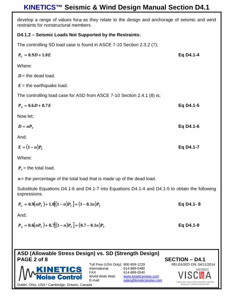
D4.1.2 – Seismic Loads Not Supported by the Restraints:
The controlling SD load case is found in ASCE 7-10 Section 2.3.2 (7);
E.D.PU 0190 Eq D4.1-4
Where:
D = the dead load.
E = the earthquake load.
The controlling load case for ASD from ASCE 7-10 Section 2.4.1 (8) is;
E.D.PA 7060 Eq D4.1-5
Now let;
TnPD Eq D4.1-6
And;
TPnE 1 Eq D4.1-7
Where:
TP = the total load.
n= the percentage of the total load that is made up of the dead load.
Substitute Equations D4.1-6 and D4.1-7 into Equations D4.1-4 and D4.1-5 to obtain the followingexpressions.
TTTU Pn.Pn.nP.P 10110190 Eq D4.1- 8
And;
TTTA Pn..Pn.nP.P 107017060 Eq D4.1-9
KINETICS™ Seismic & Wind Design Manual Section D4.1
ASD (Allowable Stress Design) vs. SD (Strength Design)PAGE 3 of 8 SECTION – D4.1
Toll Free (USA Only): 800-959-1229 RELEASED ON: 04/11/2014International: 614-889-0480FAX 614-889-0540World Wide Web: www.kineticsnoise.comE-mail: [email protected]
Dublin, Ohio, USA Cambridge, Ontario, Canada
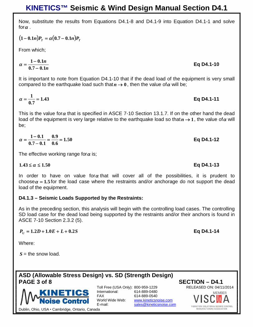
Now, substitute the results from Equations D4.1-8 and D4.1-9 into Equation D4.1-1 and solvefor .
TT Pn..Pn. 1070101
From which;
n..n.1070
101 Eq D4.1-10
It is important to note from Equation D4.1-10 that if the dead load of the equipment is very smallcompared to the earthquake load such that 0n , then the value of will be;
43170
1 ..
Eq D4.1-11
This is the value for that is specified in ASCE 7-10 Section 13.1.7. If on the other hand the deadload of the equipment is very large relative to the earthquake load so that 1n , the value of willbe;
5016090
1070101 .
.
...
. Eq D4.1-12
The effective working range for is;
501431 .. Eq D4.1-13
In order to have on value for that will cover all of the possibilities, it is prudent tochoose 51. for the load case where the restraints and/or anchorage do not support the deadload of the equipment.
D4.1.3 – Seismic Loads Supported by the Restraints:
As in the preceding section, this analysis will begin with the controlling load cases. The controllingSD load case for the dead load being supported by the restraints and/or their anchors is found inASCE 7-10 Section 2.3.2 (5).
S.LE.D.PU 200121 Eq D4.1-14
Where:
S = the snow load.

KINETICS™ Seismic & Wind Design Manual Section D4.1
ASD (Allowable Stress Design) vs. SD (Strength Design)PAGE 4 of 8 SECTION – D4.1
Toll Free (USA Only): 800-959-1229 RELEASED ON: 04/11/2014International: 614-889-0480FAX 614-889-0540World Wide Web: www.kineticsnoise.comE-mail: [email protected]
Dublin, Ohio, USA Cambridge, Ontario, Canada
L = the live load.
For ASD, the controlling load case is found in ASCE 7-10 Section 2.4.1 (6b).
S.E..L.DPA 75070750750 Eq D4.1-15
For this case, both 0S and 0L . Here, as before, Equations D4.1-6 and D4.1-7 will be used.Substitute these into Equations D4.1-14 and D4.1-15.
TTTU Pn.Pn.nP.P 20110121 Eq D4.1-16
And;
TTTA Pn..Pn..nPP 47505250170750 Eq D4.1-17
Substitute Equations D4.1-16 and D4.1-17 into Equation D4.1-1, and solve for .
TT Pn..Pn.. 30704750525
This will lead to;
n..n.47505750
201 Eq D4.1-18
Using Equation D4.1-18, the limits of this application may be examined. As 0n , the dead loadwill be small compared to the earthquake load, and the value of will be;
74157501 .
.Eq D4.1-19
When 1n , the dead weight loads far exceed the earthquake loads, and the value of will be;
14105121
47505750201 .
..
... Eq D4.1-20
For this case, the effective working range for is;
741141 .. Eq D4.1-21
In order to cover all of the possible load combinations with one value, 741. .
KINETICS™ Seismic & Wind Design Manual Section D4.1
ASD (Allowable Stress Design) vs. SD (Strength Design)PAGE 5 of 8 SECTION – D4.1
Toll Free (USA Only): 800-959-1229 RELEASED ON: 04/11/2014International: 614-889-0480FAX 614-889-0540World Wide Web: www.kineticsnoise.comE-mail: [email protected]
Dublin, Ohio, USA Cambridge, Ontario, Canada
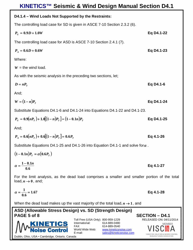
D4.1.4 – Wind Loads Not Supported by the Restraints:
The controlling load case for SD is given in ASCE 7-10 Section 2.3.2 (6).
W.D.PU 0190 Eq D4.1-22
The controlling load case for ASD is ASCE 7-10 Section 2.4.1 (7).
W.D.PA 6060 Eq D4.1-23
Where:
W = the wind load.
As with the seismic analysis in the preceding two sections, let;
TnPD Eq D4.1-6
And;
TPnW 1 Eq D4.1-24
Substitute Equations D4.1-6 and D4.1-24 into Equations D4.1-22 and D4.1-23.
TTTU Pn.Pn.nP.P 10110190 Eq D4.1-25
And;
TTTA P.Pn.nP.P 6016060 Eq 4.1-26
Substitute Equations D4.1-25 and D4.1-26 into Equation D4.1-1 and solve for .
TT P.Pn. 60101
60101
.n. Eq 4.1-27
For the limit analysis, as the dead load comprises a smaller and smaller portion of the totalload, 0n , and;
67160
1 ..
Eq 4.1-28
When the dead load makes up the vast majority of the total load, 1n , and

KINETICS™ Seismic & Wind Design Manual Section D4.1
ASD (Allowable Stress Design) vs. SD (Strength Design)PAGE 6 of 8 SECTION – D4.1
Toll Free (USA Only): 800-959-1229 RELEASED ON: 04/11/2014International: 614-889-0480FAX 614-889-0540World Wide Web: www.kineticsnoise.comE-mail: [email protected]
Dublin, Ohio, USA Cambridge, Ontario, Canada
83160
101 ..
. Eq 4.1-29
In order for a single value of to cover the entire range of load combinations between the deadload and the wind load, its value would need to be 831. .
D4.1.5 – Wind Loads Supported by the Restraints:

KINETICS™ Seismic & Wind Design Manual Section D4.1
ASD (Allowable Stress Design) vs. SD (Strength Design)PAGE 7 of 8 SECTION – D4.1
Toll Free (USA Only): 800-959-1229 RELEASED ON: 04/11/2014International: 614-889-0480FAX 614-889-0540World Wide Web: www.kineticsnoise.comE-mail: [email protected]
Dublin, Ohio, USA Cambridge, Ontario, Canada
From ASCE 7-10 Section 2.3.2 (4) the load combination for SD is found.
RorSorL.LW.D.P rU 500121 Eq D4.1-30
Where:
rL = the live roof load.
R = the rain load.
ASCE 7-10 Section 2.4.1 (6a) provides the ASD load combination.
RorSorL.W..L.DP rA 75060750750 Eq D4.1-31
In the above equations, 0RSLL r . Substitute Equations D4.1-6 and D4.1-24 intoEquations D4.1-30and D4.1-31 to yield the following results.
TTTU Pn.Pn.nP.P 20110121 Eq D4.1-32
And;
TTTA Pn..Pn..nPP 550450160750 Eq D4.1-33
Substitute Equations D4.1-32 and D4.1-33 into Equation D4.1-1 and solve for .
TT Pn..Pn. 550450201
n..n.550450
201 Eq D4.1-34
As 0n , the wind load is dominant, and;
2224501 ..
Eq D4.1-35
When 1n ; the dead load becomes dominant, and;
800550450
201 ...
. Eq D4.1-36
The effective range for will be;

KINETICS™ Seismic & Wind Design Manual Section D4.1
ASD (Allowable Stress Design) vs. SD (Strength Design)PAGE 8 of 8 SECTION – D4.1
Toll Free (USA Only): 800-959-1229 RELEASED ON: 04/11/2014International: 614-889-0480FAX 614-889-0540World Wide Web: www.kineticsnoise.comE-mail: [email protected]
Dublin, Ohio, USA Cambridge, Ontario, Canada
222800 .. Eq D4.1-37
In order to cover all of the potential load combinations with one value, 222. .
D4.1.6 – Summary:
The results of the preceding analysis for all four cases are summarized below in Table D4.1-1.
Table D4.1-1; Range of values of for Seismic and Wind Loadings
LOAD CASE FORN=05
FORN=16
For Seismic Loads When Floor & Ceiling MountedComponents are Not Supported by the Restraints 1.43 1.50
For Seismic Loads When Floor Ceiling, and Wall MountedComponents are Supported by the Restraints 1.74 1.14
For Wind Loads When Floor & Ceiling MountedComponents are Not Supported by the Restraints 1.67 1.83
For Wind Loads When Floor Ceiling, and Wall MountedComponents are Supported by the Restraints 2.22 0.80
When converting the ASD values to SD values, or visa versa, it is prudent to use the largest valuefor since the exact percentage of the total load assigned to the dead load is not normally known.
5 When n=0, the total load is made up of either the earthquake or the wind component.6 When n=1, the total load is made up of the dead weight component.

KINETICS™ Seismic & Wind Design Manual Section D4.2
HORIZ / VERT SEISMIC LOAD ENVELOPES (CONSTANT)PAGE 1 OF 3 SECTION – D4.2
Toll Free (USA Only): 800-959-1229 RELEASED ON: 04/11/2014International: 614-889-0480FAX 614-889-0540World Wide Web: www.kineticsnoise.comE-mail: [email protected]
Dublin, Ohio, USA Cambridge, Ontario, Canada
HORIZONTAL/VERTICAL SEISMIC LOADCAPACITY ENVELOPES (CONSTANT)
All seismically rated restraints that resist both horizontal and vertical loads and that areprovided by Kinetics Noise Control represent their seismic capacity with a load envelopediagram. The capacities shown conform to ASD (Applied Stress Design) methodology. Thevertical axis of the diagram is the vertical capacity of the restraint. The horizontal axis of thediagram is the horizontal capacity of the restraint. The area in between represents themaximum capacity for applications that have combined vertical and horizontal loadcomponents. Most applications involve combination of these forces. For restraints that resisthorizontal loads only, a single number identifies their capacity.
For all seismic restraints and for most seismically rated isolators, the seismic capacity isindependent of the load that the isolator might support. In some cases, however, the load beingsupported by the isolator can increase of decrease its seismic rating. This section addressesonly those isolators where the restraint capacity is unaffected by the load.
Note: The load supported does not impact the capacity of most seismically rated isolators. Anyseismically rated component that has its capacity illustrated as in the diagrams below are of the“constant” capacity type. If the seismic rating is load sensitive, the capacity diagrams will bemore complex. Refer to section D4.3 for more information on these and on how to use the loaddiagrams appropriate to them.
On most diagrams, there are two curves. One represents the capacity of the restraint whenthrough bolted and/or welded. This can also be assumed to be the capacity limit of the restraintdevice itself.
The other curve indicates the capacity of the restraint if bolted to concrete. This rating is basedon standardized anchor conditions such as normal embedment depths, 3000 psi normal weightconcrete and edge distances adequate to ensure that breakout is not a failure mode. Thesefactors can be used for 2009 and earlier IBC codes as long as the standardized conditions aremet. For later codes (2012 IBC). All anchor evaluations are required to be conducted on acase by case basis. In these cases, the anchor curves can be used as a guide, but a fullevaluation is still required by the code. Note that the anchored capacity will always be equal toor less than the through bolted capacity. It should be noted that the concrete anchoragecapacity can increase up to the limit of the through bolted capacity with the addition of optionaloversized base plates and significantly larger anchors.
In some cases, a “family” of isolators or restraints may be identified on the same diagram. Ifthis is the case, each curve will be labeled as to which family member it represents and whereappropriate, both anchored to concrete and through bolted values will be shown.

KINETICS™ Seismic & Wind Design Manual Section D4.2
HORIZ / VERT SEISMIC LOAD ENVELOPES (CONSTANT)PAGE 2 OF 3 SECTION – D4.2
Toll Free (USA Only): 800-959-1229 RELEASED ON: 04/11/2014International: 614-889-0480FAX 614-889-0540World Wide Web: www.kineticsnoise.comE-mail: [email protected]
Dublin, Ohio, USA Cambridge, Ontario, Canada
In addition, not all components are intended to be anchored to concrete. If it is not appropriatefor the given component, no associated curve will be published for it.
A typical set of curves is shown below.
Figure D4.4-1; Restraint Capacity Chart
To use the diagram, the required capacity at the various restraint (or attachment) points for theapplication must be known (or computed). There are a number of ways to obtain these values.Some of these can be fairly simple but give very conservative values. Some are morecomplicated, but may substantiate the use of lower capacity attachment hardware. As part of astandard seismic analysis for given piece of equipment, Kinetics Noise Control provides thesevalues for particular applications. The ASHRAE Handbook offers guidance on alternate waysof computing these forces and there could well be other ways to do it that result in reasonableanswers.
Some caution must be exercised though, as it is not as simple as dividing the total seismic forceby the number or isolators to get a force per isolator (See also Section D1.3 of this manual).
Once the vertical and horizontal restraint capacity necessary has been determined using ASDdesign practices, these values should be plotted on the diagram using the vertical forcecomponent for the y-variable and the horizontal force component for the x-variable. Shownbelow is a diagram with capacity requirement of 3500 lb vertical and 750 lb horizontal plottedon it. For our purposes, we will assume that the parameters used to calculate these values are“through bolted” parameters. (When using these charts, because the actual computed loadrequirement can vary depending on whether the final connection is to steel or concrete, it iscritical to ensure that the load requirement used is appropriate to the anchorage type being

KINETICS™ Seismic & Wind Design Manual Section D4.2
HORIZ / VERT SEISMIC LOAD ENVELOPES (CONSTANT)PAGE 3 OF 3 SECTION – D4.2
Toll Free (USA Only): 800-959-1229 RELEASED ON: 04/11/2014International: 614-889-0480FAX 614-889-0540World Wide Web: www.kineticsnoise.comE-mail: [email protected]
Dublin, Ohio, USA Cambridge, Ontario, Canada
considered. [Concrete anchorage forces compares to concrete allowables and through boltedforces compare to bolted allowables])
Note that the point falls between the “Anchored to Concrete” and “Bolted to Steel” curves.Because the point is inside the “Bolted to Steel” curve, this indicates two things. 1) Therestraint itself is adequate for the application and, 2) if the application involves through boltingthe restraint to the structure, the restraint can be successfully applied “as is”.
If the point had fallen outside of the “Bolted to Steel” curve, the restraint device would havebeen inadequate in size for the application and a restraint with higher capacity would have to beselected.
If the force had been computed using “Anchored to Concrete” parameters, because the pointfalls outside of the anchored to concrete curve, it indicates that if connecting to concrete usingpost installed anchors, the restraint cannot be used “as is”. Since it does fall inside the “Boltedto Steel” curve however, it indicates that it could be fitted with an oversized baseplate and more(or larger) anchor bolts. If this oversized baseplate is sized to resist these forces, it offers aviable attachment option. Details on selecting an adequate oversized baseplates can be foundin the Floor and Wall Mounted Equipment Chapter, Section D5.2.
Figure D4.4-2; Restraint Capacity Chart with Load Point
If the point had fallen inside of the “Anchored to Concrete” curve, the restraint could have beenused “as is” in the anchored to concrete application.

KINETICS™ Seismic & Wind Design Manual Section D4.3
HORIZ/VERT SEISMIC LOAD ENVELOPES (VARIABLE)PAGE 1 of 4 SECTION – D4.3
Toll Free (USA Only): 800-959-1229 RELEASED ON: 04/11/2014International: 614-889-0480FAX 614-889-0540World Wide Web: www.kineticsnoise.comE-mail: [email protected]
Dublin, Ohio, USA Cambridge, Ontario, Canada
HORIZONTAL/VERTICAL SEISMIC LOADCAPACITY ENVELOPES (VARIABLE)
All seismically rated restraints that resist both horizontal and vertical loads and that areprovided by Kinetics Noise Control represent their seismic capacity with an ASD Based loadenvelope diagram as indicated in the previous section. In some cases involving combinedisolation and restraint devices however, the supported load can significantly impact the lateral,vertical or combined capacity. This requires the creation of a special load diagram appropriateto the specific load being supported.
Once developed, the vertical axis of the diagram indicates the vertical capacity of the restraintand the horizontal axis of the diagram is the horizontal capacity of the restraint in the samemanner as does the “Constant” load capacity envelope. (See also D4.2)
Figure D4.3-1; Typical “Constant” capacity Envelope
In general, when working with a restraint that has “Variable” load capacity, increases in thesupported load will make restraints more stable (and resistant to lateral loads) and will increasethe applied force necessary to overcome gravity forces (and increase their effectiveness indealing with uplift loads).
If the seismically rated isolator, however, is designed with a cantilever element that transfersthe load from both the spring and the snubber to the supported piece of equipment, the actualstress in the component is the resultant of these two factors. As the supported load increases,the maximum restraint load will decrease and vice versa. This relationship is typically linearand needs to be taken into account when sizing the restraint component.
KINETICS™ Seismic & Wind Design Manual Section D4.3
HORIZ/VERT SEISMIC LOAD ENVELOPES (VARIABLE)PAGE 2 of 4 SECTION – D4.3
Toll Free (USA Only): 800-959-1229 RELEASED ON: 04/11/2014International: 614-889-0480FAX 614-889-0540World Wide Web: www.kineticsnoise.comE-mail: [email protected]
Dublin, Ohio, USA Cambridge, Ontario, Canada
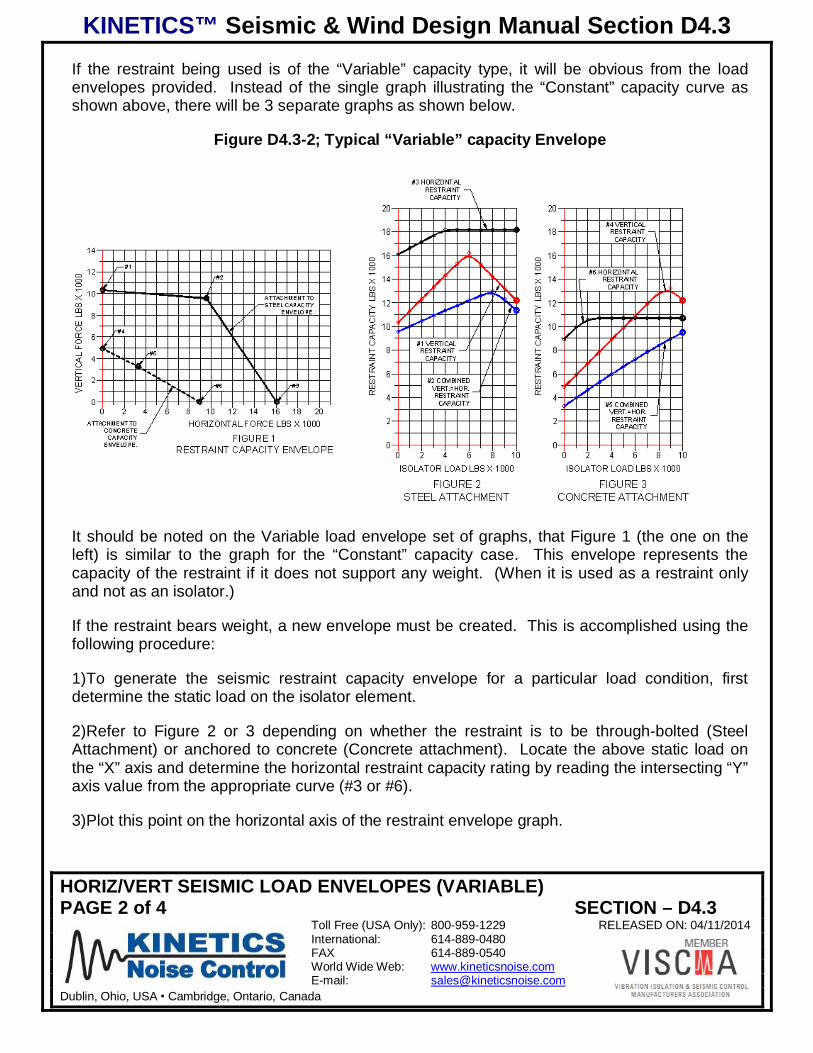
If the restraint being used is of the “Variable” capacity type, it will be obvious from the loadenvelopes provided. Instead of the single graph illustrating the “Constant” capacity curve asshown above, there will be 3 separate graphs as shown below.
Figure D4.3-2; Typical “Variable” capacity Envelope
It should be noted on the Variable load envelope set of graphs, that Figure 1 (the one on theleft) is similar to the graph for the “Constant” capacity case. This envelope represents thecapacity of the restraint if it does not support any weight. (When it is used as a restraint onlyand not as an isolator.)
If the restraint bears weight, a new envelope must be created. This is accomplished using thefollowing procedure:
1) To generate the seismic restraint capacity envelope for a particular load condition, firstdetermine the static load on the isolator element.
2) Refer to Figure 2 or 3 depending on whether the restraint is to be through-bolted (SteelAttachment) or anchored to concrete (Concrete attachment). Locate the above static load onthe “X” axis and determine the horizontal restraint capacity rating by reading the intersecting “Y”axis value from the appropriate curve (#3 or #6).
3) Plot this point on the horizontal axis of the restraint envelope graph.

KINETICS™ Seismic & Wind Design Manual Section D4.3
HORIZ/VERT SEISMIC LOAD ENVELOPES (VARIABLE)PAGE 3 of 4 SECTION – D4.3
Toll Free (USA Only): 800-959-1229 RELEASED ON: 04/11/2014International: 614-889-0480FAX 614-889-0540World Wide Web: www.kineticsnoise.comE-mail: [email protected]
Dublin, Ohio, USA Cambridge, Ontario, Canada
4) Similarly determine and plot the vertical restraint rating drawn from curve #1 or #4 on thevertical axis of the restraint envelope graph.
5) Repeat for the combined rating (curve #2 or #5) and plot it at the location where both thevertical and horizontal force equal this value.
6) Connect the above points to generate the performance envelope for the restraint under theparticular load condition.
Example
Assume we have a seismically rated restraint that supports 600 lb and we want to derive arestraint capacity curve for it.
Using the sample graph below, we can see that the horizontal capacity with a 600 lb supportload is 2650 lb (Curve #3), The vertical capacity is 2000 lb (Curve #1) and the combinedcapacity is 1100 (Curve #2).
Figure D4.3-3; Sample Graph
Plotting these values on the Restraint Capacity Envelope curve, we produce a curve that lookslike the dashed line shown on the following page.

KINETICS™ Seismic & Wind Design Manual Section D4.3
HORIZ/VERT SEISMIC LOAD ENVELOPES (VARIABLE)PAGE 4 of 4 SECTION – D4.3
Toll Free (USA Only): 800-959-1229 RELEASED ON: 04/11/2014International: 614-889-0480FAX 614-889-0540World Wide Web: www.kineticsnoise.comE-mail: [email protected]
Dublin, Ohio, USA Cambridge, Ontario, Canada
Also shown on this diagram is the unloaded restraint curve and added is a curve indicating thecapacity for this particular restraint if it were to be loaded to the maximum (1000 lb.)
At this point, the curve can be applied in the same manner as the constant capacity envelopeaddressed in the previous section of the manual.
Figure D4.3-4; Generated Seismic Load Capacity Envelope
KINETICS™ Seismic & Wind Design Manual Section D4.4
QuakeLoc SEISMIC SWAY BRACING SYSTEMPAGE 1 of 50 SECTION – D4.4
Toll Free (USA Only): 800-959-1229 RELEASED ON: 04/11/2014International: 614-889-0480FAX 614-889-0540World Wide Web: www.kineticsnoise.comE-mail: [email protected]
Dublin, Ohio, USA Cambridge, Ontario, Canada
QuakeLoc SEISMIC SWAY BRACING SYSTEM
D4.4.1 - Introduction
The Kinetics QuakeLoc seismic sway bracing system is a tension only bracing system designedto maintain the position of non-structural components to the structure during seismic events.QuakeLoc cable assemblies are mounted in opposing pairs to resist horizontal forces applied tonon-structural components. These cable pairs mount both longitudinally and transversely to thecomponents to maintain the components position in all directions.
QuakeLoc bracing systems designed per these guidelines do not guarantee adequacy ofthe existing structures to withstand the loads induced by the seismic attachments. It isthe responsibility of the structural engineer or record to verify that the structure is capable ofresisting any and all loads added to the structure as a result of the use of the QuakeLoc swaybracing system. The project engineer and installer shall determine the placement andinstallation of braces according to these guidelines and in compliance with all applicable codes.
This bracing system is intended for use on internal building components only. The QuakeLocsystem is not intended as a sway brace for fire sprinkler system piping. Loads restrained arelimited to seismic loads and do not include loads due to wind, thermal expansion, pressure, fluiddynamics, etc.
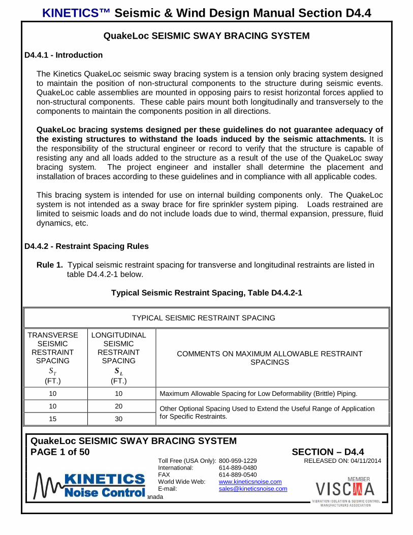
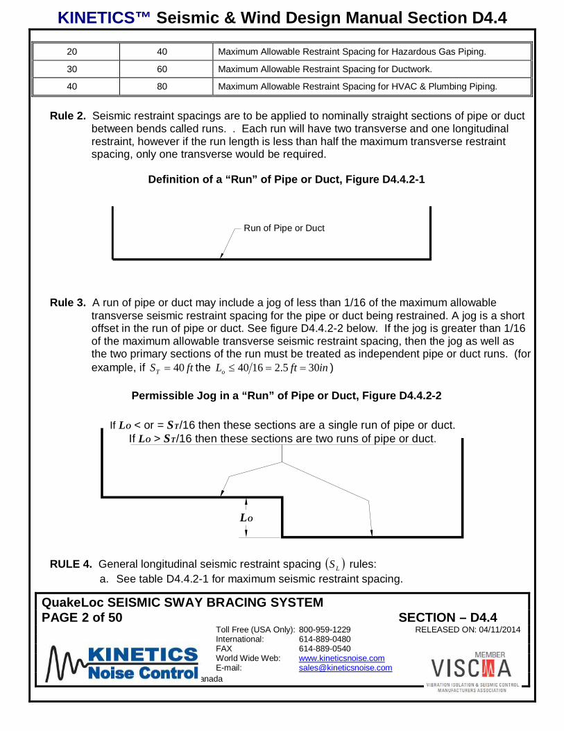
D4.4.2 - Restraint Spacing Rules
Rule 1. Typical seismic restraint spacing for transverse and longitudinal restraints are listed intable D4.4.2-1 below.
Typical Seismic Restraint Spacing, Table D4.4.2-1
TYPICAL SEISMIC RESTRAINT SPACING
TRANSVERSESEISMIC
RESTRAINTSPACING
TS(FT.)
LONGITUDINALSEISMIC
RESTRAINTSPACING
LS(FT.)
COMMENTS ON MAXIMUM ALLOWABLE RESTRAINTSPACINGS
10 10 Maximum Allowable Spacing for Low Deformability (Brittle) Piping.
10 20 Other Optional Spacing Used to Extend the Useful Range of Applicationfor Specific Restraints.15 30
KINETICS™ Seismic & Wind Design Manual Section D4.4
QuakeLoc SEISMIC SWAY BRACING SYSTEMPAGE 2 of 50 SECTION – D4.4
Toll Free (USA Only): 800-959-1229 RELEASED ON: 04/11/2014International: 614-889-0480FAX 614-889-0540World Wide Web: www.kineticsnoise.comE-mail: [email protected]
Dublin, Ohio, USA Cambridge, Ontario, Canada
20 40 Maximum Allowable Restraint Spacing for Hazardous Gas Piping.
30 60 Maximum Allowable Restraint Spacing for Ductwork.
40 80 Maximum Allowable Restraint Spacing for HVAC & Plumbing Piping.
Rule 2. Seismic restraint spacings are to be applied to nominally straight sections of pipe or ductbetween bends called runs. . Each run will have two transverse and one longitudinalrestraint, however if the run length is less than half the maximum transverse restraintspacing, only one transverse would be required.
Definition of a “Run” of Pipe or Duct, Figure D4.4.2-1
Run of Pipe or Duct
Rule 3. A run of pipe or duct may include a jog of less than 1/16 of the maximum allowabletransverse seismic restraint spacing for the pipe or duct being restrained. A jog is a shortoffset in the run of pipe or duct. See figure D4.4.2-2 below. If the jog is greater than 1/16of the maximum allowable transverse seismic restraint spacing, then the jog as well asthe two primary sections of the run must be treated as independent pipe or duct runs. (forexample, if ftST 40 the inftLo 305.21640 )
Permissible Jog in a “Run” of Pipe or Duct, Figure D4.4.2-2
If LO < or = ST/16 then these sections are a single run of pipe or duct.If LO > ST/16 then these sections are two runs of pipe or duct.
LO
RULE 4. General longitudinal seismic restraint spacing LS rules:a. See table D4.4.2-1 for maximum seismic restraint spacing.

KINETICS™ Seismic & Wind Design Manual Section D4.4
QuakeLoc SEISMIC SWAY BRACING SYSTEMPAGE 3 of 50 SECTION – D4.4
Toll Free (USA Only): 800-959-1229 RELEASED ON: 04/11/2014International: 614-889-0480FAX 614-889-0540World Wide Web: www.kineticsnoise.comE-mail: [email protected]
Dublin, Ohio, USA Cambridge, Ontario, Canada
b. Maximum longitudinal seismic restraint spacing, LS , should not exceed twice themaximum allowable transverse seismic restraint spacing, TL SS 2 , unlessindependently analyzed by a qualified individual.
c. If the run length is greater than the maximum longitudinal seismic restraint spacing,additional longitudinal restraints may be required to reduce the distance betweenlongitudinal restraints to be equal to or less than the maximum spacing forlongitudinal restraints.
d. Longitudinal seismic restraints maybe placed anywhere along the run, but must bewithin 4in of a pipe or duct hanger location.
e. Longitudinal restraints shall be mounted +/- 10° to the longitudinal axis ofcomponent.
RULE 5. General transverse seismic restraint spacing TS rules:
a. See table D4.4.2-1 for maximum seismic restraint spacing.b. Transverse seismic restraints are to be located at or with in 4in of pipe or duct
hanger location.c. If run is over half the maximum allowable transverse seismic restraint spacing and
less than or equal to the maximum allowable transverse seismic restraint spacing inlength, each straight run of pipe or duct must have a transverse seismic restraint ateach end of the run.
d. If the run is longer than the maximum allowable for transverse seismic restraints,additional transverse seismic must be added until the distance between transverseseismic restraints is less than the maximum.
e. If the run is under half of the maximum allowable spacing for transverse seismicrestraint, only one transverse seismic restraint is required anywhere along the run.
f. Transverse restraint to be mounted perpendicular to the component within +/- 10°
Maximum Restraint Spacing, Figure D4.4.2-3
Typical HangerLocation
Pipe/Duct Run
Additional TransverseSeismic Restraint
SL
Additional LongitudinalSeismic Restraint
SH
ST

KINETICS™ Seismic & Wind Design Manual Section D4.4
QuakeLoc SEISMIC SWAY BRACING SYSTEMPAGE 4 of 50 SECTION – D4.4
Toll Free (USA Only): 800-959-1229 RELEASED ON: 04/11/2014International: 614-889-0480FAX 614-889-0540World Wide Web: www.kineticsnoise.comE-mail: [email protected]
Dublin, Ohio, USA Cambridge, Ontario, Canada
Rule 6. For QuakeKit cable restraints, the installation angle A may be between 0° and 60° asmeasured from the horizontal. See figure D4.4.2-4.
Permitted Range of Restraint Cable Installation Angles, Figure D4.4.2-4
A= 0° to 60°
TRANSVERSECABLE RESTRAINT
A=0° to 60°
LONGITUDINALCABLE RESTRAINT
Rule 7. Longitudinal seismic restraints for single clevis hung pipe must be attached directly to thepipe in a manner similar to that shown in figures D4.4.2-5 and D4.4.2-6. The seismicrestraints maybe attached to the pipe using a pipe clamp as shown in figure D4.4.2-5.
Longitudinal Restraint Connection Overview, Figure D4.4.2-5
4" MAX

KINETICS™ Seismic & Wind Design Manual Section D4.4
QuakeLoc SEISMIC SWAY BRACING SYSTEMPAGE 5 of 50 SECTION – D4.4
Toll Free (USA Only): 800-959-1229 RELEASED ON: 04/11/2014International: 614-889-0480FAX 614-889-0540World Wide Web: www.kineticsnoise.comE-mail: [email protected]
Dublin, Ohio, USA Cambridge, Ontario, Canada
Longitudinal Restraint Connection Detail, Figure D4.4.2-6
KNC
KHRC-BQuakeKit-PRestraint
Cable Kits
Pipe Clamp - Rotate Pipe ClampUntil Cables Miss Hanger Rod & Stiffener
4"MAX
UseThimblesto Protect
Cables
Rule 8. Where smaller pipes branch off from larger pipes, the seismic restraints on the smallerpipe cannot be used as seismic restraints for the larger pipe.
Rule 9. Transverse seismic restraints located within 24in of a 90° bend can serve as thelongitudinal restraint for the other leg.
Corner Restraints Doing “Double Duty”, Figure D4.4.2-7
1
2
24"Max.
24"Max.
Transverse for 1Longitudinal for 2
Transverse for 2Longitudinal for 1
Pipe q
KINETICS™ Seismic & Wind Design Manual Section D4.4
QuakeLoc SEISMIC SWAY BRACING SYSTEMPAGE 6 of 50 SECTION – D4.4
Toll Free (USA Only): 800-959-1229 RELEASED ON: 04/11/2014International: 614-889-0480FAX 614-889-0540World Wide Web: www.kineticsnoise.comE-mail: [email protected]
Dublin, Ohio, USA Cambridge, Ontario, Canada
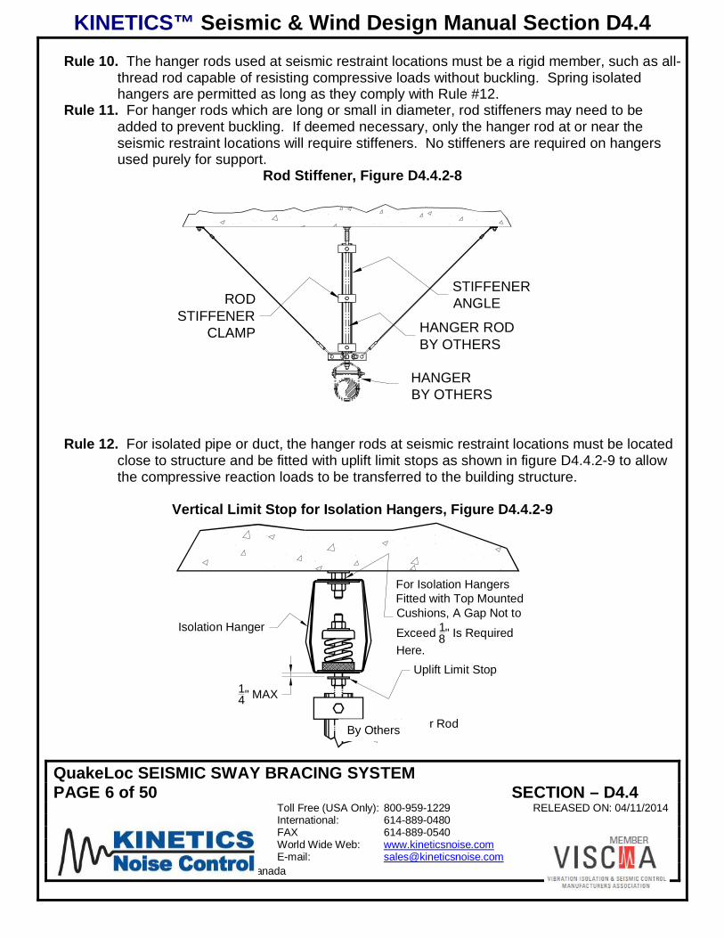
Rule 10. The hanger rods used at seismic restraint locations must be a rigid member, such as all-thread rod capable of resisting compressive loads without buckling. Spring isolatedhangers are permitted as long as they comply with Rule #12.
Rule 11. For hanger rods which are long or small in diameter, rod stiffeners may need to beadded to prevent buckling. If deemed necessary, only the hanger rod at or near theseismic restraint locations will require stiffeners. No stiffeners are required on hangersused purely for support.
Rod Stiffener, Figure D4.4.2-8
HANGER RODBY OTHERS
STIFFENERANGLEROD
STIFFENERCLAMP
HANGERBY OTHERS
Rule 12. For isolated pipe or duct, the hanger rods at seismic restraint locations must be locatedclose to structure and be fitted with uplift limit stops as shown in figure D4.4.2-9 to allowthe compressive reaction loads to be transferred to the building structure.
Vertical Limit Stop for Isolation Hangers, Figure D4.4.2-9
14" MAX
Uplift Limit Stop
Isolation Hanger
Hanger Rod
For Isolation HangersFitted with Top MountedCushions, A Gap Not to
Exceed 18" Is Required
Here.
By Others

KINETICS™ Seismic & Wind Design Manual Section D4.4
QuakeLoc SEISMIC SWAY BRACING SYSTEMPAGE 7 of 50 SECTION – D4.4
Toll Free (USA Only): 800-959-1229 RELEASED ON: 04/11/2014International: 614-889-0480FAX 614-889-0540World Wide Web: www.kineticsnoise.comE-mail: [email protected]
Dublin, Ohio, USA Cambridge, Ontario, Canada
Rule 13. For vertical drops to equipment a flexible coupling will be required to account for relativemotion between the piping and the equipment. If the pipe or duct drop is less or equal tohalf of the transverse seismic restraint spacing, 2/TSH , seismic restraints are notrequired for the drop, provided that there is a transverse seismic restraint within 24” of thetop elbow of the drop. If, however, the drop is greater than half the transverse seismicrestraint spacing, the bottom of the drop will need to be restrained to structure with a “4-way” restraint to limit horizontal movement in all directions.
Drops and Restraints for Piping/Ducts under ST/2 in Length, Figure D4.4.2-10
H
HORIZONTAL PIPE RUN
TRANSVERSE RESTRAINT AT THEEND OF THE HORIZONTAL RUN
EQUIPMENT
PROVIDE FLEXIBLE COUPLINGFOR ISOLATED EQUIPMENT
BY OTHERS
24"MAX
IF H< or =(ST/2) NO ADDITIONALRESTRAINT IS REQUIRED ATTHIS LOCATION.
Rule 14. For code based exemptions to these rules refer to ASCE/SE 7-10 section 13.
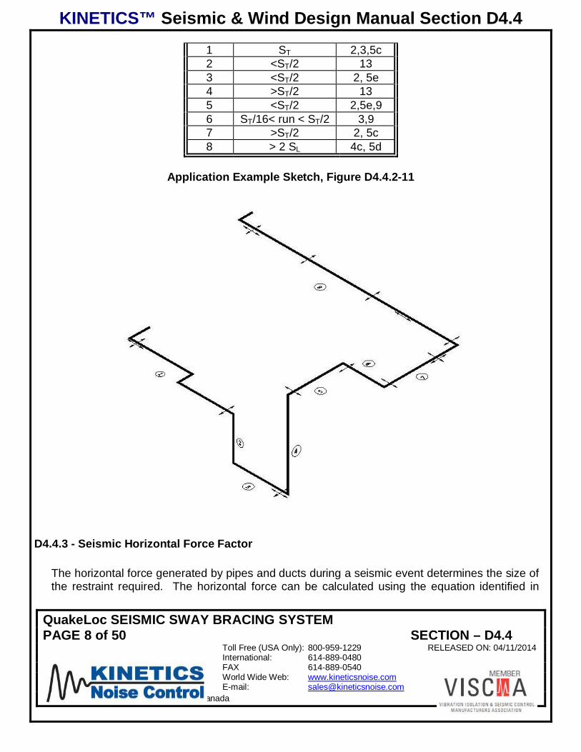
The example below shows a portion of a cold water piping system with seismic restraintsapplied. The table lists the pipe run, length of the run based on maximum allowable restraintspacing and the rules that apply to the application of seismic restraints for that run of pipe.
Typical Application Example, Table D4.4.2-2
RunRun Length
based on maxspacing
Rule
KINETICS™ Seismic & Wind Design Manual Section D4.4
QuakeLoc SEISMIC SWAY BRACING SYSTEMPAGE 8 of 50 SECTION – D4.4
Toll Free (USA Only): 800-959-1229 RELEASED ON: 04/11/2014International: 614-889-0480FAX 614-889-0540World Wide Web: www.kineticsnoise.comE-mail: [email protected]
Dublin, Ohio, USA Cambridge, Ontario, Canada
1 ST 2,3,5c2 <ST/2 133 <ST/2 2, 5e4 >ST/2 135 <ST/2 2,5e,96 ST/16< run < ST/2 3,97 >ST/2 2, 5c8 > 2 SL 4c, 5d
Application Example Sketch, Figure D4.4.2-11
D4.4.3 - Seismic Horizontal Force Factor
The horizontal force generated by pipes and ducts during a seismic event determines the size ofthe restraint required. The horizontal force can be calculated using the equation identified in

KINETICS™ Seismic & Wind Design Manual Section D4.4
QuakeLoc SEISMIC SWAY BRACING SYSTEMPAGE 9 of 50 SECTION – D4.4
Toll Free (USA Only): 800-959-1229 RELEASED ON: 04/11/2014International: 614-889-0480FAX 614-889-0540World Wide Web: www.kineticsnoise.comE-mail: [email protected]
Dublin, Ohio, USA Cambridge, Ontario, Canada
Section D2.1.8 of this manual. For the purposes of this chapter, the equation can be re-writtenas:
hz
RISa
Gp
pDSp 214.0
where all the factors that modify the component operating weight (Wp ) can be combined intoone factor (G). This variable (G) would be the factor applied to the operational weight whichyields the horizontal seismic force factor. This resulting output force generated be this equationwould yield an LRFD based value.
G shall be between the following limits
pDSpDS ISGIS 6.13.0
Substituting G into the seismic horizontal force equation the equation becomes:
pp GWF
D4.4.4 Restraint Cable Size and Anchorage Selection Procedure
1. Determine restraint spacing for transverse and longitudinal restraints in accordance tospacing rules section D4.4.2.
2. Determine the weight per foot of pipe or duct being restrained. This weight includes weightof content, insulation, lining, etc in addition to the pipe or duct weight. The weight per foot ofindividually supported, water filled, insulated standard pipe is identified on the graph directly.For multiple components on a trapeze, the weights of all components must be summed.
3. Select the appropriate “Maximum Cable and Anchor Capacities” graph from figures D4.4.4-1through D4.4.4-6. Based on the structural attachment condition.
4. Using the appropriate “Maximum Cable and Anchor Capacities” graph, find the weight beingrestrained associated with the restraint being evaluated.
A. For single supported pipe or duct.
a. Determine the length of the span of pipe or duct that will be restrained by therestraint of interest. This is typically the restraint spacing.

KINETICS™ Seismic & Wind Design Manual Section D4.4
QuakeLoc SEISMIC SWAY BRACING SYSTEMPAGE 10 of 50 SECTION – D4.4
Toll Free (USA Only): 800-959-1229 RELEASED ON: 04/11/2014International: 614-889-0480FAX 614-889-0540World Wide Web: www.kineticsnoise.comE-mail: [email protected]
Dublin, Ohio, USA Cambridge, Ontario, Canada
b. Find the restraint span as indicated above on the lower vertical axis of thegraph .
c. Project a horizontal line to intersect with the diagonal line for the weight perfoot being restrained from step 2.
d. From this point, project a vertical line up to the left horizontal axis to find theweight restrained by the restraint being evaluated.
B. For trapeze hangers.
a. Determine the length of the span of pipe or duct that will be restrained by therestraint of interest. This is typically the restraint spacing.
b. Find the restraint span as indicated above on the lower vertical axis of thegraph .
c. Project a horizontal line to intersect with the diagonal line for the total weightper foot of the items being supported on the trapeze from step 2.
d. From this point, project a vertical line up to the left horizontal axis to find thetotal weight being restrained on the trapeze restraint being evaluated.
5. Determine horizontal seismic force.
A. Project a line vertically upward into the left quadrant of the graph from the weightfound above to the required G factor diagonal line determined in section D4.4.3.
B. From this point project horizontally to the upper vertical axis to find the horizontalseismic force on the restraint being evaluated.
6. Sizing cables and anchors
A. Project horizontal line from the seismic force axis into the upper right quadrant of thegraph to the angle of installation .
B. Cable and anchor sizes shown above this point are acceptable for this application.
Linear interpolation is permitted

KINETICS™ Seismic & Wind Design Manual Section D4.4
QuakeLoc SEISMIC SWAY BRACING SYSTEMPAGE 11 of 50 SECTION – D4.4
Toll Free (USA Only): 800-959-1229 RELEASED ON: 04/11/2014International: 614-889-0480FAX 614-889-0540World Wide Web: www.kineticsnoise.comE-mail: [email protected]
Dublin, Ohio, USA Cambridge, Ontario, Canada
C. If no acceptable anchors are found to be above the installation angle, seismic forcepoint, the restraint span must be reduced. This is true even if a cable capacity isabove the point listed.
D. If the point falls above a listed cable capacity, and below a listed anchor capacity,the capacity will be limited to that of the cable.
E. If no cable or anchor capacities are identified as being above the installation angle,seismic force point, the restraint span must be reduced.

KINETICS™ Seismic & Wind Design Manual Section D4.4
QuakeLoc SEISMIC SWAY BRACING SYSTEMPAGE 12 of 50 SECTION – D4.4
Toll Free (USA Only): 800-959-1229 RELEASED ON: 04/11/2014International: 614-889-0480FAX 614-889-0540World Wide Web: www.kineticsnoise.comE-mail: [email protected]
Dublin, Ohio, USA Cambridge, Ontario, Canada
Through Bolt Selection Chart, Figure D4.4.4-1
KINETICS™ Seismic & Wind Design Manual Section D4.4
QuakeLoc SEISMIC SWAY BRACING SYSTEMPAGE 13 of 50 SECTION – D4.4
Toll Free (USA Only): 800-959-1229 RELEASED ON: 04/11/2014International: 614-889-0480FAX 614-889-0540World Wide Web: www.kineticsnoise.comE-mail: [email protected]
Dublin, Ohio, USA Cambridge, Ontario, Canada
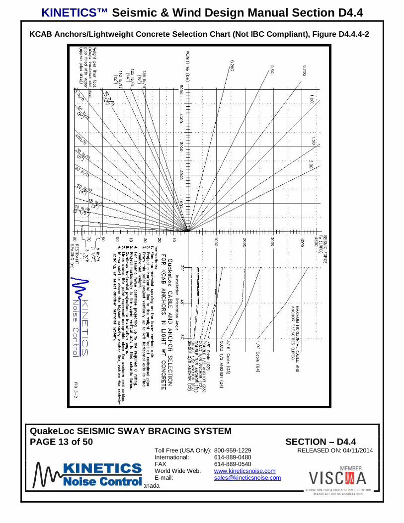
KCAB Anchors/Lightweight Concrete Selection Chart (Not IBC Compliant), Figure D4.4.4-2

KINETICS™ Seismic & Wind Design Manual Section D4.4
QuakeLoc SEISMIC SWAY BRACING SYSTEMPAGE 14 of 50 SECTION – D4.4
Toll Free (USA Only): 800-959-1229 RELEASED ON: 04/11/2014International: 614-889-0480FAX 614-889-0540World Wide Web: www.kineticsnoise.comE-mail: [email protected]
Dublin, Ohio, USA Cambridge, Ontario, Canada
KCAB Anchors/Normal Weight Concrete Selection Chart (Not IBC Compliant), FigureD4.4.4-3

KINETICS™ Seismic & Wind Design Manual Section D4.4
QuakeLoc SEISMIC SWAY BRACING SYSTEMPAGE 15 of 50 SECTION – D4.4
Toll Free (USA Only): 800-959-1229 RELEASED ON: 04/11/2014International: 614-889-0480FAX 614-889-0540World Wide Web: www.kineticsnoise.comE-mail: [email protected]
Dublin, Ohio, USA Cambridge, Ontario, Canada
KCCAB Anchors/Lightweight Concrete Selection Chart, Figure D4.4.4-4

KINETICS™ Seismic & Wind Design Manual Section D4.4
QuakeLoc SEISMIC SWAY BRACING SYSTEMPAGE 16 of 50 SECTION – D4.4
Toll Free (USA Only): 800-959-1229 RELEASED ON: 04/11/2014International: 614-889-0480FAX 614-889-0540World Wide Web: www.kineticsnoise.comE-mail: [email protected]
Dublin, Ohio, USA Cambridge, Ontario, Canada
KCCAB Anchors/Normal weight Concrete Selection Chart, Figure D4.4.4-5

KINETICS™ Seismic & Wind Design Manual Section D4.4
QuakeLoc SEISMIC SWAY BRACING SYSTEMPAGE 17 of 50 SECTION – D4.4
Toll Free (USA Only): 800-959-1229 RELEASED ON: 04/11/2014International: 614-889-0480FAX 614-889-0540World Wide Web: www.kineticsnoise.comE-mail: [email protected]
Dublin, Ohio, USA Cambridge, Ontario, Canada
Lag Screw Attached Selection Chart, Figure D4.4.4-6

KINETICS™ Seismic & Wind Design Manual Section D4.4
QuakeLoc SEISMIC SWAY BRACING SYSTEMPAGE 18 of 50 SECTION – D4.4
Toll Free (USA Only): 800-959-1229 RELEASED ON: 04/11/2014International: 614-889-0480FAX 614-889-0540World Wide Web: www.kineticsnoise.comE-mail: [email protected]
Dublin, Ohio, USA Cambridge, Ontario, Canada
D4.4.5 - Cable and Attachment Codes
The table below gives a reference for the codes used in the capacity graphs for cable selection.Q designates a QuakeLoc kit and the size of the cable. X designates either a single bolt or postinstalled concrete wedge anchor. Z’s designate the use of a over-sized base plate with multiplepost installed concrete wedge anchors. Finally, W’s designate lag screws to be used forattachment to wood.
Cable Restraint Component Codes, Table D4.4.5-1
Code Designation Size
Q2 Quakekit 1/8”cable
Q3 Quakekit 3/16”cable
Q4 Quakekit 1/4"cable
X2 Bolt orAnchor 3/8”
X3 Bolt orAnchor 1/2"
Z1 Anchors 2x3/8”
Z2 “ 4x3/8"
Z3 “ 2x1/2"
Z4 Anchors 4x1/2"
W2 Lag Screw 3/8”W3 “ 1/2"
W7 “ 2x3/8”
W8 “ 2x1/2"
W9 “ 4x3/8”
W10 Lag Screw 4x1/2"

KINETICS™ Seismic & Wind Design Manual Section D4.4
QuakeLoc SEISMIC SWAY BRACING SYSTEMPAGE 19 of 50 SECTION – D4.4
Toll Free (USA Only): 800-959-1229 RELEASED ON: 04/11/2014International: 614-889-0480FAX 614-889-0540World Wide Web: www.kineticsnoise.comE-mail: [email protected]
Dublin, Ohio, USA Cambridge, Ontario, Canada
CABLE SEAT
D4.4.6 QuakeLoc Assembly Procedure
Tools Required: Torque Wrench with Hex Bit Socket:1/8” Hex (1/8” QuakeLoc), 5/32” Hex (3/16” QuakeLoc), 3/16” Hex (1/4” QuakeLoc).
1) Feed the cable througheither end of the QuakeLocas shown. The cable shouldrest in the bottom of the slotor cable seat.
2) Place a cablethimble through theKSCA or KSUAattachment bracket.
QuakeKit-D cablerestraint kits containKSUA bracketsonly. KSUA
KSCA
KINETICS™ Seismic & Wind Design Manual Section D4.4
QuakeLoc SEISMIC SWAY BRACING SYSTEMPAGE 20 of 50 SECTION – D4.4
Toll Free (USA Only): 800-959-1229 RELEASED ON: 04/11/2014International: 614-889-0480FAX 614-889-0540World Wide Web: www.kineticsnoise.comE-mail: [email protected]
Dublin, Ohio, USA Cambridge, Ontario, Canada
SETSCREWS
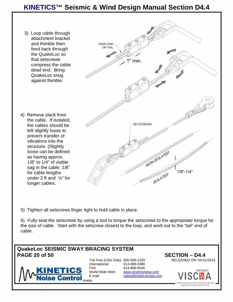
5) Tighten all setscrews finger tight to hold cable in place.
6) Fully seat the setscrews by using a tool to torque the setscrews to the appropriate torque forthe size of cable. Start with the setscrew closest to the loop, and work out to the “tail” end ofcable.
3) Loop cable throughattachment bracketand thimble thenfeed back throughthe QuakeLoc sothat setscrewscompress the cabledead end. BringQuakeLoc snugagainst thimble.
4) Remove slack fromthe cable. If isolated,the cables should beleft slightly loose toprevent transfer ofvibrations into thestructure. (Slightlyloose can be definedas having approx.1/8” to 1/4” of visiblesag in the cable. 1/8”for cable lengthsunder 2 ft and ¼” forlonger cables.
DEAD ENDOR TAIL

KINETICS™ Seismic & Wind Design Manual Section D4.4
QuakeLoc SEISMIC SWAY BRACING SYSTEMPAGE 21 of 50 SECTION – D4.4
Toll Free (USA Only): 800-959-1229 RELEASED ON: 04/11/2014International: 614-889-0480FAX 614-889-0540World Wide Web: www.kineticsnoise.comE-mail: [email protected]
Dublin, Ohio, USA Cambridge, Ontario, Canada
S
S Size (in) T Torque (in-lb)651/8"1303/16"2001/4"
(Top of screw will be slightly below top of housing when properly torqued)
7) Installation is now complete.
D4.4.7 – QuakeLoc Kit Attachment to Structure
D4.4.7.1 – KSCA Brackets – Basic Sizes & Installation:The Kinetics Noise Control Model KSCA bracket was originally designed to be a part of a clampassembly that would allow the restraint cables to be attached to hanger rods. However, overtime, the KSCA bracket has proven to be useful for attaching the restraint cables to the buildingstructure. The KSCA bracket as part of a bolted or anchored structural attachment is shown inFigures D4.4.7-1, D4.4.7-2, D4.4.7-3, D4.4.7-4 and D4.4.7-5. Notice in Figure D4.4.7-5, that thesingle hole beyond the bend is used for attaching the cable to the bracket. A thimble will beneeded in this loop to prevent damage to the cable. A QuakeKit seismic restraint cable kitconsists of two 1/8”, 3/16” or ¼” restraint cables with a loop swaged on one end, two KSCAattachment brackets, two Kinetics provided end connectors, two Kinetics Model KSUAattachment brackets (which will be described in detail in the Section D4.4.9) and ½” mountinghardware. Prior to attaching restraints to the structure, the Engineer of Record should reviewthe proposed method of attachment as well as the projected loads and grant his approval.

KINETICS™ Seismic & Wind Design Manual Section D4.4
QuakeLoc SEISMIC SWAY BRACING SYSTEMPAGE 22 of 50 SECTION – D4.4
Toll Free (USA Only): 800-959-1229 RELEASED ON: 04/11/2014International: 614-889-0480FAX 614-889-0540World Wide Web: www.kineticsnoise.comE-mail: [email protected]
Dublin, Ohio, USA Cambridge, Ontario, Canada
General Information on Attaching the KSCA Bracket to Structure, Figure D4.4.7-1
KINE
TIC
KSC
A
DO NOT Use This Hole forStructural Attachments!!
Cable Attachment Hole18 in. thru 1
4 in. Cable Sizes
KineticsCable
Connector
For Detail SeeFigure 5-2
Structural Fastener Hole38 in. or 1
2 in. Bolt orAnchor Sizes
Kinetics ModelKSCA Bracket
Detail of KSCA Bracket When Used with Smaller Bolts/Anchors, Figure D4.4.7-2
Use Bronze Flanged Bearing Supplied with
Attachment Kit for38 in. Fasteners.
D4.4.7.2 – KSCA Brackets – Attachment to Steel:
KSCA brackets are most easily attached to structural steel by welding, see Figures D4.4.7-3 andD4.4.7-4. Figure D4.4.7-5 which shows the KSCA bracket attached to structural steel AISC W,M, S, or HP shapes without welding.

KINETICS™ Seismic & Wind Design Manual Section D4.4
QuakeLoc SEISMIC SWAY BRACING SYSTEMPAGE 23 of 50 SECTION – D4.4
Toll Free (USA Only): 800-959-1229 RELEASED ON: 04/11/2014International: 614-889-0480FAX 614-889-0540World Wide Web: www.kineticsnoise.comE-mail: [email protected]
Dublin, Ohio, USA Cambridge, Ontario, Canada
KSCA Bracket Attachment to Steel (Horizontal Orientation), Figure D4.4.7-3
Both Sides3/16
Both Sides3/16
112 Typ 11
2 Typ
KSCA Bracket Attachment to Steel (Vertical Orientation), Figure D4.4.7-4
Both Sides3/16
Both Sides3/16
112 Typ
112 Typ

KINETICS™ Seismic & Wind Design Manual Section D4.4
QuakeLoc SEISMIC SWAY BRACING SYSTEMPAGE 24 of 50 SECTION – D4.4
Toll Free (USA Only): 800-959-1229 RELEASED ON: 04/11/2014International: 614-889-0480FAX 614-889-0540World Wide Web: www.kineticsnoise.comE-mail: [email protected]
Dublin, Ohio, USA Cambridge, Ontario, Canada
KSCA Bracket Attachment Using a KSBC (Seismic Beam Clamp), Figure D4.4.7-5
Rod Goes in Hole Closestthe Bend in the Long Legof the KSCA Bracket!
Use Neoprene Grommet as Shownin Figure 5-2 for Model KSBC-1Seismic Beam Clamp.
D4.4.7.3 – KSCA Brackets – Attachment to Concrete:
KSCA brackets should not be attached directly to light weight concrete. This is due to the factthat the contact area of a KSCA bracket is small enough that the light weight concrete may becrushed when tightening the fasteners. This will lead to the bracket being loose and increasedshock loads during an earthquake. KSCA brackets may be attached directly to normal weightconcrete as shown in Figure D4.4.7-6. All concrete anchor recommendations in this report arebased on the Kinetics recommended KSCC.
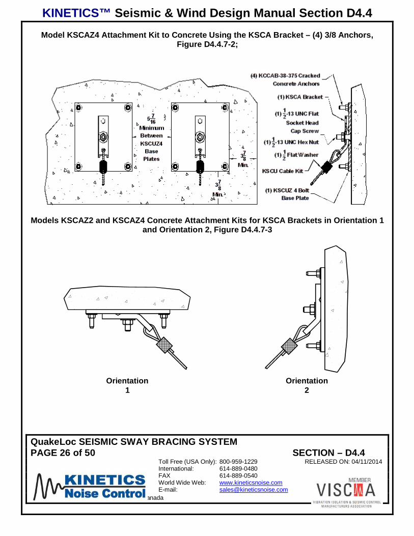
There may be certain instances where a single anchor with a KSUA bracket or a KSCA bracketwill not have enough capacity. Then the KSCAZ2, two concrete anchor, and KSCAZ4, fourconcrete anchor, kits may be used, shown in Figures D4.4.7-7, D4.4.7-8, 5-9, and D4.4.7-10.

KINETICS™ Seismic & Wind Design Manual Section D4.4
QuakeLoc SEISMIC SWAY BRACING SYSTEMPAGE 25 of 50 SECTION – D4.4
Toll Free (USA Only): 800-959-1229 RELEASED ON: 04/11/2014International: 614-889-0480FAX 614-889-0540World Wide Web: www.kineticsnoise.comE-mail: [email protected]
Dublin, Ohio, USA Cambridge, Ontario, Canada
Typical KSCA Bracket Installation in Normal Weight Concrete, Figure D4.4.7-6
H OH ef
DO
H min
Cmin Smin
DO
Smin
Cmin
H ef
H min
H O
Orientation1
Orientation2
Model KSCAZ2 Attachment Kit to Concrete Using the KSCA Bracket – (2) 3/8 Anchors,Figure D4.4.7-1
KINETICS™ Seismic & Wind Design Manual Section D4.4
QuakeLoc SEISMIC SWAY BRACING SYSTEMPAGE 26 of 50 SECTION – D4.4
Toll Free (USA Only): 800-959-1229 RELEASED ON: 04/11/2014International: 614-889-0480FAX 614-889-0540World Wide Web: www.kineticsnoise.comE-mail: [email protected]
Dublin, Ohio, USA Cambridge, Ontario, Canada
Model KSCAZ4 Attachment Kit to Concrete Using the KSCA Bracket – (4) 3/8 Anchors,Figure D4.4.7-2;
Models KSCAZ2 and KSCAZ4 Concrete Attachment Kits for KSCA Brackets in Orientation 1and Orientation 2, Figure D4.4.7-3
Orientation2
Orientation1 Sheet B - View D

KINETICS™ Seismic & Wind Design Manual Section D4.4
QuakeLoc SEISMIC SWAY BRACING SYSTEMPAGE 27 of 50 SECTION – D4.4
Toll Free (USA Only): 800-959-1229 RELEASED ON: 04/11/2014International: 614-889-0480FAX 614-889-0540World Wide Web: www.kineticsnoise.comE-mail: [email protected]
Dublin, Ohio, USA Cambridge, Ontario, Canada
Anchor Hole Drill Template for Models KSCAZ2 and KSCAZ4, Figure D4.4.7-4
916
916
678
Ø38 Drill for Anchors
678
D4.4.8 – KSCA Brackets – Attachment to Wooden StructuresAttachment of seismic or wind restraints to a wooden structure requires carefulcoordination with the building structural engineer. While wooden structures tend to performbetter during an earthquake than their concrete, masonry, or sometimes even steel counterparts,individual restraint attachments and point loads can adversely affect the strength andperformance of the building structure. This is because the location of grain irregularities, knots,splits and checks cannot be controlled. The building structural engineer can indicate the properlocations and load capacity limits for each restraint attachment type and location. Figure D4.4.8-1 and Table D4.4.8-1 show the typical installation dimensions that will apply to lag screwattachments.

KINETICS™ Seismic & Wind Design Manual Section D4.4
QuakeLoc SEISMIC SWAY BRACING SYSTEMPAGE 28 of 50 SECTION – D4.4
Toll Free (USA Only): 800-959-1229 RELEASED ON: 04/11/2014International: 614-889-0480FAX 614-889-0540World Wide Web: www.kineticsnoise.comE-mail: [email protected]
Dublin, Ohio, USA Cambridge, Ontario, Canada
Figure D4.4.8-5 Typical Lag Screw Installation Dimensions, Figure D4.4.8-6
S E1
D
E3
TE2
d
L
Lag Screw and Through Bolt Installation Data for Model KSCU Restraint Cable Kits, TableD4.4.8-1
LAG SCREW&
THROUGH BOLTSIZE
D(IN)
LAG SCREWPILOT HOLE
SIZED
(IN)
SCREW&
BOLTMINIMUMSPACING
S(IN)
SCREW&
BOLTMINIMUM
ENDDISTANCE
E1(IN)
SCREW&
BOLTMINIMUM
EDGEDISTANCE
E2(IN)
LAG SCREWEMBEDMENT
DOES NOTINCLUDE SCREW
POINTE3(IN)
SoftWood
HardWood
3/8 3/16 1/4 1-1/2 1-1/2 9/16 31/2 15/64 21/64 2 2 3/4 4
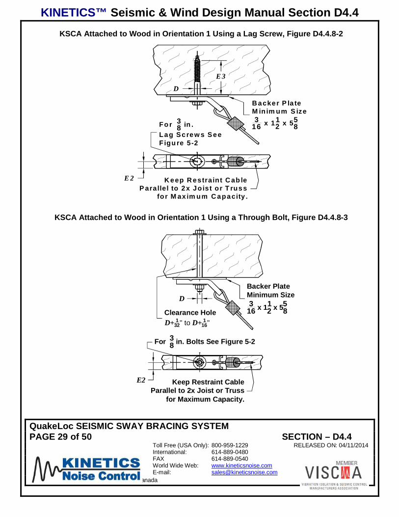
KSCA brackets installed in Orientation 1 to structural wood are shown in Figure D4.4.8-2 for alag screw attachment and Figure D4.4.8-3 for a through bolted attachment. KSCA bracketsused from attachment to wood applications will require steel backer plates beneath theKSCA bracket to prevent damage to the wood!
KINETICS™ Seismic & Wind Design Manual Section D4.4
QuakeLoc SEISMIC SWAY BRACING SYSTEMPAGE 29 of 50 SECTION – D4.4
Toll Free (USA Only): 800-959-1229 RELEASED ON: 04/11/2014International: 614-889-0480FAX 614-889-0540World Wide Web: www.kineticsnoise.comE-mail: [email protected]
Dublin, Ohio, USA Cambridge, Ontario, Canada
KSCA Attached to Wood in Orientation 1 Using a Lag Screw, Figure D4.4.8-2
K eep R estraint C ab leP arallel to 2x Joist or T russ
for M ax im um C apacity .
E 3
D
Fo r 38 in .
Lag Screw s SeeFigu re 5-2
E 2
B acker P la teM inim um S ize3
16 x 112 x 55
8
KSCA Attached to Wood in Orientation 1 Using a Through Bolt, Figure D4.4.8-3
Clearance HoleD+ 1
32" to D+ 116"
D
Keep Restraint CableParallel to 2x Joist or Truss
for Maximum Capacity.
For 38 in. Bolts See Figure 5-2
E2
Backer PlateMinimum Size3
16 x 112 x 55
8

KINETICS™ Seismic & Wind Design Manual Section D4.4
QuakeLoc SEISMIC SWAY BRACING SYSTEMPAGE 30 of 50 SECTION – D4.4
Toll Free (USA Only): 800-959-1229 RELEASED ON: 04/11/2014International: 614-889-0480FAX 614-889-0540World Wide Web: www.kineticsnoise.comE-mail: [email protected]
Dublin, Ohio, USA Cambridge, Ontario, Canada
Special Note: Seismic and wind restraints are not to be attached to the end grain ofstructural wood!!
KSCA brackets installed in Orientation 2 to structural wood are shown in Figure D4.4.8-4 for alag screw attachment and Figure D4.4.8-5 for a through bolted attachment.
KSCA Attached to Wood in Orientation 2 Using a Lag Screw, Figure D4.4.8-4
Keep Restraint Cable Parallelto Stud for Maximum Capacity.
E3
D
E2
Backer PlateMinimum Size
316 x 11
2 x 558
For 38 in. Lag Screws
See Figure 5-2
KSCA Attached to Wood in Orientation 2 Using a Through Bolt, Figure D4.4.8-5
D
C learance HoleD+ 1
32" to D + 116"E2
For 38 in . Bolts
See F igure 5-2
Backer P lateM inim um Size
316 x 11
2 x 558
K eep Restraint Cable Parallelto Stud for M axim um C apacity .

KINETICS™ Seismic & Wind Design Manual Section D4.4
QuakeLoc SEISMIC SWAY BRACING SYSTEMPAGE 31 of 50 SECTION – D4.4
Toll Free (USA Only): 800-959-1229 RELEASED ON: 04/11/2014International: 614-889-0480FAX 614-889-0540World Wide Web: www.kineticsnoise.comE-mail: [email protected]
Dublin, Ohio, USA Cambridge, Ontario, Canada
The KSCA bracket may be attached to the sides of wooden joists and beams in Orientation 2as shown in Figure 5-16 for lag screw attachment and Figure 5-17 for through bolt attachment.
KSCA Attached to a Wooden Joist or Beam in Orientation 2 Using a Lag Screw, FigureD4.4.8-6
H
H/2 Min.But Greater
Than 3"
E3
DFor 1
4 & 38 Lag Screws
See Figure 5-2
Backer PlateMinimum
316 x 11
2 x 558
KSCA Attached to a Wooden Joist or Beam in Orientation 2 Using a Through Bolt, FigureD4.4.8-7
D
Clearance HoleD+ 1
32" to D+ 116"
Backer Plate Minimum3
16 x 112 x 55
8
For 14 & 3
8 BoltsSee FIgure 5-2 H
H/2 Min.But Greater
Than 3"
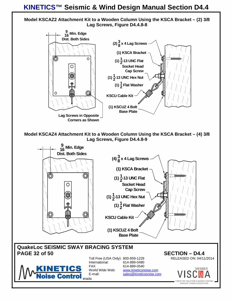
The KSCAZ2 and KSCAZ4 attachment kits will allow the KSCA bracket to be mounted to awooden structural member using two or four lag screws. Figures D4.4.8-8 and D4.4.9-9 showthe KSCAZ2 and KSCAZ4, respectively, mounted to a wooden column.
KINETICS™ Seismic & Wind Design Manual Section D4.4
QuakeLoc SEISMIC SWAY BRACING SYSTEMPAGE 32 of 50 SECTION – D4.4
Toll Free (USA Only): 800-959-1229 RELEASED ON: 04/11/2014International: 614-889-0480FAX 614-889-0540World Wide Web: www.kineticsnoise.comE-mail: [email protected]
Dublin, Ohio, USA Cambridge, Ontario, Canada
Model KSCAZ2 Attachment Kit to a Wooden Column Using the KSCA Bracket – (2) 3/8Lag Screws, Figure D4.4.8-8
16 Min. EdgeDist. Both Sides
(1) KSCUZ 4 BoltBase Plate
(1) 12-13 UNC FlatSocket Head
Cap Screw(1) 1
2-13 UNC Hex Nut
(1) 12 Flat Washer
(1) KSCA Bracket
(2) 38 x 4 Lag Screws
KSCU Cable Kit
Lag Screws in OppositeCorners as Shown
Model KSCAZ4 Attachment Kit to a Wooden Column Using the KSCA Bracket – (4) 3/8Lag Screws, Figure D4.4.8-9
(1) KSCUZ 4 BoltBase Plate
(1) 12-13 UNC FlatSocket Head
Cap Screw(1) 1
2-13 UNC Hex Nut
(1) 12 Flat Washer
(1) KSCA Bracket
(4) 38 x 4 Lag Screws
KSCU Cable Kit
916 Min. Edge
Dist. Both Sides
KINETICS™ Seismic & Wind Design Manual Section D4.4
QuakeLoc SEISMIC SWAY BRACING SYSTEMPAGE 33 of 50 SECTION – D4.4
Toll Free (USA Only): 800-959-1229 RELEASED ON: 04/11/2014International: 614-889-0480FAX 614-889-0540World Wide Web: www.kineticsnoise.comE-mail: [email protected]
Dublin, Ohio, USA Cambridge, Ontario, Canada
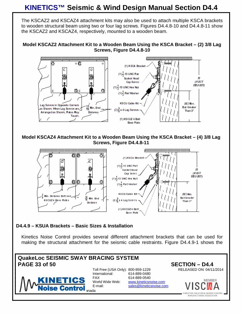
The KSCAZ2 and KSCAZ4 attachment kits may also be used to attach multiple KSCA bracketsto wooden structural beam using two or four lag screws. Figures D4.4.8-10 and D4.4.8-11 showthe KSCAZ2 and KSCAZ4, respectively, mounted to a wooden beam.
Model KSCAZ2 Attachment Kit to a Wooden Beam Using the KSCA Bracket – (2) 3/8 LagScrews, Figure D4.4.8-10
Model KSCAZ4 Attachment Kit to a Wooden Beam Using the KSCA Bracket – (4) 3/8 LagScrews, Figure D4.4.8-11
D4.4.9 – KSUA Brackets – Basic Sizes & Installation
Kinetics Noise Control provides several different attachment brackets that can be used formaking the structural attachment for the seismic cable restraints. Figure D4.4.9-1 shows the

KINETICS™ Seismic & Wind Design Manual Section D4.4
QuakeLoc SEISMIC SWAY BRACING SYSTEMPAGE 34 of 50 SECTION – D4.4
Toll Free (USA Only): 800-959-1229 RELEASED ON: 04/11/2014International: 614-889-0480FAX 614-889-0540World Wide Web: www.kineticsnoise.comE-mail: [email protected]
Dublin, Ohio, USA Cambridge, Ontario, Canada
KSUA-2 bracket supplied with QuakeLoc Kits. The KSUA-2 bracket comes pre-installed withthimble in the swaged loop end of all sizes of QuakeLoc cables.
Kinetics Noise Control Model KSUA Seismic Restraint Cable Attachment Brackets,Figure D4.4.9-1
A°
ØD
Ødw
t
Primarily, the KSUA attachment brackets are used with the Kinetics Noise Control Model KSCUand QuakeKit Seismic Restraint Cable Kits.
Installation of Model KSUA Attachment Bracket, Figure D4.4.9-2
View #2Side
KSUA - Open
View #3Side
KSUA - Closed
View #1Front
KSUA - Installed
KINETICS™ Seismic & Wind Design Manual Section D4.4
QuakeLoc SEISMIC SWAY BRACING SYSTEMPAGE 35 of 50 SECTION – D4.4
Toll Free (USA Only): 800-959-1229 RELEASED ON: 04/11/2014International: 614-889-0480FAX 614-889-0540World Wide Web: www.kineticsnoise.comE-mail: [email protected]
Dublin, Ohio, USA Cambridge, Ontario, Canada
In addition to the KSUA attachment bracket pre-installed in the swaged loop end of the restraintcable, the KSUA bracket can also be used on the QuakeLoc end of the cable where the loop ismade along with a thimble. Figure D4.4.9-2 shows the basic installation of the KSUA brackets.The particular installation shown is for attachment to the building structural concrete, althoughthe basic procedure is the same regardless of whether the bracket is being attached tostructural steel, concrete, or wood.
1. The open KSUA bracket is placed over the fastener, with (for a 3/8” anchor) or without (for a1/2" anchor) a flat washer, and the nut is run down finger tight on the bracket. See View #2 SideKSUA – Open in Figure D4.4.9-2 above.2. Tighten the nut with a wrench to the proper torque specified for the fastener being used. Thetwo legs of the KSUA bracket should be squeezed shut as shown in View # 3 Side KSUA –Closed as shown in Figure D4.4.9-2. Squeezing the legs of the KSUA bracket shut will form aloop for the restraint cable. The cable should be loose and free to move inside the loop of theKSUA bracket.
D4.4.9-1 – KSUA Brackets – Attachment to Steel:
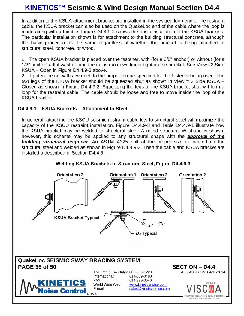
In general, attaching the KSCU seismic restraint cable kits to structural steel will maximize thecapacity of the KSCU restraint installation. Figure D4.4.9-3 and Table D4.4.9-1 illustrate howthe KSUA bracket may be welded to structural steel. A rolled structural W shape is shown;however, this scheme may be applied to any structural shape with the approval of thebuilding structural engineer. An ASTM A325 bolt of the proper size is located on thestructural steel and welded as shown in Figure D4.4.9-3. Then the cable and KSUA bracket areinstalled a described in Section D4.4.6.
Welding KSUA Brackets to Structural Steel, Figure D4.4.9-3
h
DB Typical
Sheet C - Views F, K, M, and N
TypKSUA Bracket Typical
Orientation 1 Orientation 2 Orientation 2Orientation 2

KINETICS™ Seismic & Wind Design Manual Section D4.4
QuakeLoc SEISMIC SWAY BRACING SYSTEMPAGE 36 of 50 SECTION – D4.4
Toll Free (USA Only): 800-959-1229 RELEASED ON: 04/11/2014International: 614-889-0480FAX 614-889-0540World Wide Web: www.kineticsnoise.comE-mail: [email protected]
Dublin, Ohio, USA Cambridge, Ontario, Canada
Bolt and Weld Size for KSUA Bracket Weld Attachment to Structural Steel, Table D4.4.9-1
KSUABRACKET
BOLT SIZEDB
WELD SIZEH
(IN)
KSUA-1 3/8-16 UNC 3/16KSUA-2 1/2-13 UNC 1/4
Kinetics Noise Control offers Models KSBC-1 and -2 Seismic Beam Clamps that may be usedto attach the KSUA brackets to structural steel AISC W, M, S, or HP shapes without welding.This method of attachment to structural steel is shown in Figure 5-25. Here also, the use of theseismic beam clamps to attach the KSUA brackets to the structural steel must be approved bythe building structural engineer.
Using Model KSBC Seismic Beam Clamps to Attach KSUA Brackets to Structural Steel,Figure D4.4.9-4
Sheet C - View J
KSBC-2 Seism ic BeamClam p & KSUA-2 CableAttachm ent Bracket
KSUA Brackets may be attached to steel open web joists as shown in Figures D4.4.9-5 andD4.4.9-6. These structural elements are normally designed to be as efficient as possible whichmeans that they are designed to carry primarily vertical loads, and frequently have little capacitybeyond the code mandated loads. As a result, if seismic restraints for pipe and duct are to beattached to these open web steel joists, it is absolutely necessary for the building structuralengineer to approve each attachment point.

KINETICS™ Seismic & Wind Design Manual Section D4.4
QuakeLoc SEISMIC SWAY BRACING SYSTEMPAGE 37 of 50 SECTION – D4.4
Toll Free (USA Only): 800-959-1229 RELEASED ON: 04/11/2014International: 614-889-0480FAX 614-889-0540World Wide Web: www.kineticsnoise.comE-mail: [email protected]
Dublin, Ohio, USA Cambridge, Ontario, Canada
Attaching KSUA Brackets to Cross-Braced Open Web Steel Joists, Figure D4.4.9-5
Sheet C - View A
Use at Cross-BraceLocation Only!
Otherwise FollowFigure I5-6.
KSUA Bracket
Attaching KSUA Brackets to Un-Braced Open Web Steel Joists, Figure D4.4.9-6
Sheet C - View G
KSUA Bracket
KINETICS™ Seismic & Wind Design Manual Section D4.4
QuakeLoc SEISMIC SWAY BRACING SYSTEMPAGE 38 of 50 SECTION – D4.4
Toll Free (USA Only): 800-959-1229 RELEASED ON: 04/11/2014International: 614-889-0480FAX 614-889-0540World Wide Web: www.kineticsnoise.comE-mail: [email protected]
Dublin, Ohio, USA Cambridge, Ontario, Canada
D4.4.9-2 – KSUA Brackets – Attachment to Concrete:
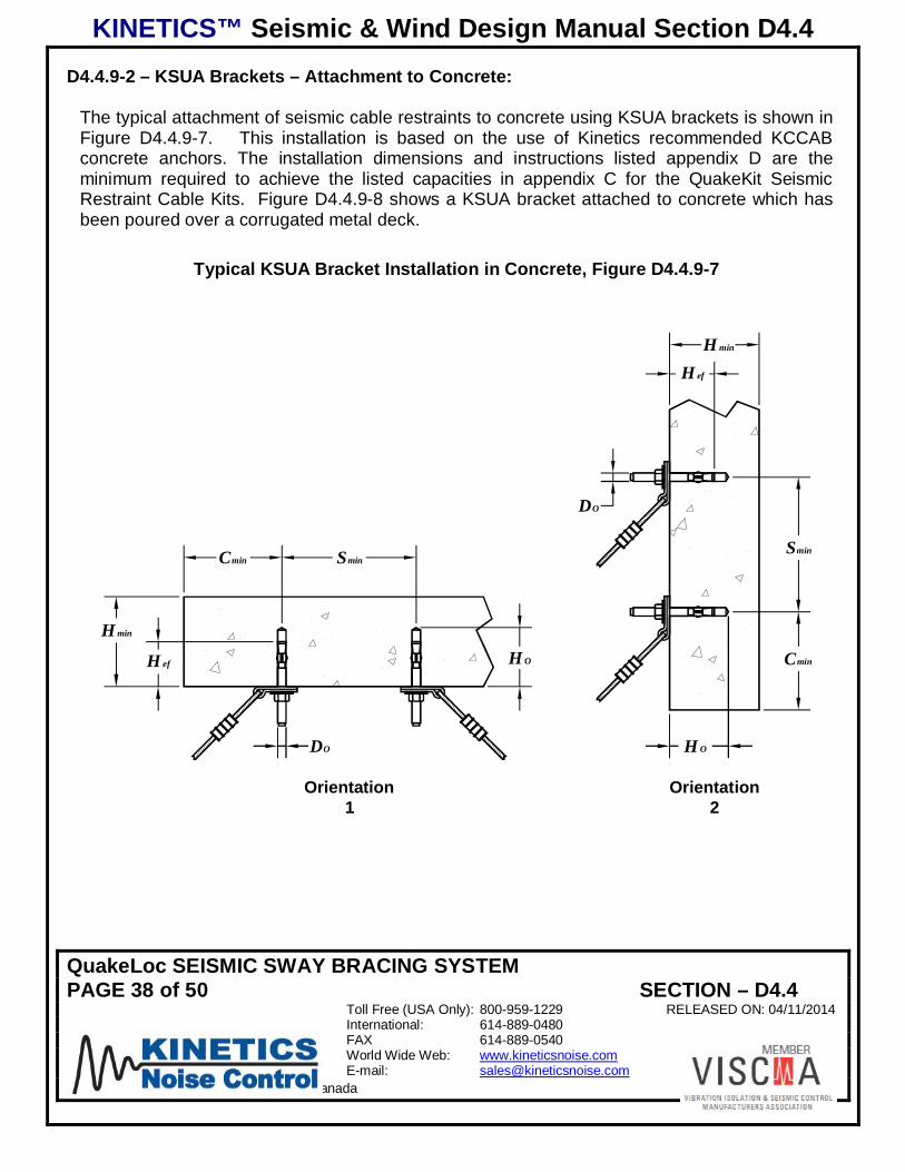
The typical attachment of seismic cable restraints to concrete using KSUA brackets is shown inFigure D4.4.9-7. This installation is based on the use of Kinetics recommended KCCABconcrete anchors. The installation dimensions and instructions listed appendix D are theminimum required to achieve the listed capacities in appendix C for the QuakeKit SeismicRestraint Cable Kits. Figure D4.4.9-8 shows a KSUA bracket attached to concrete which hasbeen poured over a corrugated metal deck.
Typical KSUA Bracket Installation in Concrete, Figure D4.4.9-7
H OH ef
DO
H min
Cmin Smin
DO
Smin
Cmin
H ef
H min
H O
Orientation1
Orientation2
Sheet B - View A

KINETICS™ Seismic & Wind Design Manual Section D4.4
QuakeLoc SEISMIC SWAY BRACING SYSTEMPAGE 39 of 50 SECTION – D4.4
Toll Free (USA Only): 800-959-1229 RELEASED ON: 04/11/2014International: 614-889-0480FAX 614-889-0540World Wide Web: www.kineticsnoise.comE-mail: [email protected]
Dublin, Ohio, USA Cambridge, Ontario, Canada
KSUA Bracket Attached to Concrete Poured on Corrugated Metal Decking, Figure D4.4.9-8
Locate Anchor inCenter of ThickestConcrete Section
at the Ribs
KSUA Bracket
D4.4.10 - Hanger Rod Stiffeners
Using cable restraints such as the QuakeLoc series always creates an upward vertical force intothe hanger rod when the cable restrains the component from moving in a horizontal direction asshown in figure D4.4.10-1 below. The vertical force, results from one of the cable restraintsalways being in tension. This force only applies at locations where a seismic restraint attachesto a component hanger. All other hangers only support the hanging weight of the componentand are not subject to this additional upward vertical force.
The vertical force from the tension in the cable restraint can be found from the formula below.
ATanFF Pv
While this upward vertical force will not increase the load on the hanger rod due to the weight ofthe pipe or duct being supported, it could place the hanger rod in compression and cause it tobuckle. Buckling is a condition that causes catastrophic failure in long slender columns.Buckling risk depends on the compressive load, hanger rod size and length.
The use of rod stiffeners protects the hanger rod from a buckling failure. A stiffener in the formof equal length leg steel angles attached to the hanger rod increases the rod resistance tobuckling. The stiffener acts with the hanger rod to resist the upward compressive force from thecable restraint. If found to be necessary, rod stiffeners need only be fitted to hanger rodsattached to or in the immediate vicinity of seismic restraints.
Compression Forces Generated in Hanger Rod, Figure D4.4.10-1

KINETICS™ Seismic & Wind Design Manual Section D4.4
QuakeLoc SEISMIC SWAY BRACING SYSTEMPAGE 40 of 50 SECTION – D4.4
Toll Free (USA Only): 800-959-1229 RELEASED ON: 04/11/2014International: 614-889-0480FAX 614-889-0540World Wide Web: www.kineticsnoise.comE-mail: [email protected]
Dublin, Ohio, USA Cambridge, Ontario, Canada
T
FP
V R
W R
A
T
V R
W R
FP
A
Typical Hanger Rod Stiffener Installation, Figure D4.4.10-2
Rod Stiffener AngleHanger Rod by Others
Rod Stiffener Clamp
Jam Nut
Clamp Bolt1.) Center clamp bolt on hanger rod.2.) Tighten clamp bolt securely.3.) Tighten jam nut against clamp body.
A
Kinetics Noise Control Model KHRC-B Hanger Rod Stiffener Clamp, Figure D4.4.10-3

KINETICS™ Seismic & Wind Design Manual Section D4.4
QuakeLoc SEISMIC SWAY BRACING SYSTEMPAGE 41 of 50 SECTION – D4.4
Toll Free (USA Only): 800-959-1229 RELEASED ON: 04/11/2014International: 614-889-0480FAX 614-889-0540World Wide Web: www.kineticsnoise.comE-mail: [email protected]
Dublin, Ohio, USA Cambridge, Ontario, Canada
KINETICS
KHRC-B
138
[35]
2 [51]
318
[79]
38-16 UNC x 2
HEX HD. BOLT38-16 UNC
HEX JAM NUT
RANGE OF STIFFENERANGLES
AISC STANDARD METRIC1 x 1 x 1/8 25 x 25 x 3
1-1/4 x 1-1/4 x 1/4 30 x 30 x 51-1/2 x 1-1/2 x 1/4 40 x 40 x 6
RANGE OF HANGERRODS
INCHSTANDARD
METRICSTANDARD
3/8 M101/2 M125/8 M163/4 M207/8 M221 M24
1-1/8 M30
Kinetics Noise Control Model KHRC-C Hanger Rod Stiffener Clamp, Figure D4.4.10-4
KINETICS
KHRC-C
138
[35]4 716
[113]
218
[54]
38-16 UNC x 21
2HEX HD. BOLT
38-16 UNCHEX JAM NUT
RANGE OF STIFFENERANGLES
AISC STANDARD METRIC1-3/4 x 1-3/4 x 1/4 45 x 45 x 6
2 x 2 x 1/4 50 x 50 x 62 x 2 x 3/8 50 x 50 x 8
2-1/2 x 2-1/2 x 1/4 60 x 60 x 6
RANGE OF HANGERRODS
INCHSTANDARD
METRICSTANDARD
3/8 M101/2 M125/8 M163/4 M207/8 M221 M24
1-1/8 M301-1/4 M36
D4.4.11 – Hanger Rod Stiffener Selection and Clamp Requirement Procedure

KINETICS™ Seismic & Wind Design Manual Section D4.4
QuakeLoc SEISMIC SWAY BRACING SYSTEMPAGE 42 of 50 SECTION – D4.4
Toll Free (USA Only): 800-959-1229 RELEASED ON: 04/11/2014International: 614-889-0480FAX 614-889-0540World Wide Web: www.kineticsnoise.comE-mail: [email protected]
Dublin, Ohio, USA Cambridge, Ontario, Canada
1. Determine spacing of hanger rods, transverse restraints and longitudinal restraints2. Determine weight per foot of pipe or duct being restrained including any insulation, liner and
content. (wp)3. Use the “Hanger rod vertical compressive load” graph figure D4.4.11-1 to find the upward
vertical load being placed on the hanger rod.A. Weight supported by hanger rod RW
a. Find the hanger spacing on the lower vertical axis of the graphb. Project a horizontal line for the hanger spacing to the diagonal weight per foot line.
(Wf)c. From this intersection, project a vertical line up to the left horizontal axis to find the
weight being supported by the hanger. RWd. For evenly loaded trapeze bars, the hanger rod carries only half of the supported
weight. If the load is offset to one side, proportion the weight accordingly and set WRequal to the lighter of the 2 supported weights.
B. Vertical compressive load applied to the hanger by the restraint. VFa. Find the restraint spacing on the lower vertical axis of the graph.b. Project a horizontal line for the restraint spacing to the diagonal weight per foot line.c. From this intersection, project a vertical line up to the required G factor.d. From this point, project a horizontal line to the line for the restraint installation angle.e. From this intersection, project a vertical line down to the right horizontal axis to find
vertical component of the restraint force. VF .f. For trapeze hung components the hanger rod will still carry the full vertical
compressive load.
C. Subtract the weight supported by the hanger from the vertical component of the restraintforce to find vertical force being placed on the hanger rod.
Single hung Trapeze hung (Evenly Loaded)
RVF WFV 2R
VFWFV
If the result is 0 or a negative number, the weight hanging for the hanger rod is equal to orgreater than the vertical component of the restraint force, so no stiffener rod will berequired.
4. If uplift is present, determine if stiffener is requireda. On the appropriate “Hanger Rod Buckling” graph (figure D4.4.11-2, D4.4.11-3 &
D4.4.11-4) identify the vertical compressive force found above in step 3C on thevertical axis of the graph.
b. Locate the hanger rod length L on the horizontal axis of the graph.c. Find the curve for the hanger rod size on the graphd. If the intersection of the vertical force and rod length is below the hanger rod size line,
no stiffener will be required.

KINETICS™ Seismic & Wind Design Manual Section D4.4
QuakeLoc SEISMIC SWAY BRACING SYSTEMPAGE 43 of 50 SECTION – D4.4
Toll Free (USA Only): 800-959-1229 RELEASED ON: 04/11/2014International: 614-889-0480FAX 614-889-0540World Wide Web: www.kineticsnoise.comE-mail: [email protected]
Dublin, Ohio, USA Cambridge, Ontario, Canada
e. If the intersection of the vertical force and hanger rod length is on or above the hangerrod size curve, a stiffener will be required.
f. On trapeze hung components, stiffeners are required only on hanger rods that areattached to the restrained end of the trapeze bar. If restraints are fitted to both ends ofthe trapeze, stiffeners are to be fitted on both ends as well.
5. Find acceptable rod stiffenersa. On the “Stiffener Buckling” graph (figure D4.4.11-5) identify the vertical compressive
force from step 3C above on the vertical axis of the graph.b. Locate the hanger rod length on the horizontal axis of the graph.c. Find the intersection of the vertical compressive force and hanger rod length on the
graph.d. Any stiffener identified by a capacity line that is above this point will make an
acceptable hanger rod stiffener.
6. Determine number and spacing of stiffener rod clamps
a. Using the appropriate “Maximum Stiffener Clamp Spacing” graph (figures D4.4.11-6,D4.4.11-7 & D4.4.11-8), find the vertical force FV from step 3C on the vertical axis ofthe graph.
b. Project a horizontal line to intersect with the hanger rod size curve being used.c. Project a vertical line down to the he horizontal axis of the graph to find the maximum
distance between stiffener clamps. SCSd. Find the number of stiffener clamps SCN by dividing the hanger rod length L by the
maximum distance between stiffener clamps SCS and add 1. Round this number up tothe next whole number to find the number of stiffener clamps required.
1SC
SC SLN
e. Stiffener clamps are to be evenly spaced along the length of the hanger rod. Thislength can be found by subtracting 1 from the number of clamps required and thendividing the hanger rod length by this number.
1__
SCNLspacingclampStiffener
Hanger Rod Compression Chart, Figure D4.4.11-1

KINETICS™ Seismic & Wind Design Manual Section D4.4
QuakeLoc SEISMIC SWAY BRACING SYSTEMPAGE 44 of 50 SECTION – D4.4
Toll Free (USA Only): 800-959-1229 RELEASED ON: 04/11/2014International: 614-889-0480FAX 614-889-0540World Wide Web: www.kineticsnoise.comE-mail: [email protected]
Dublin, Ohio, USA Cambridge, Ontario, Canada
Rod Bucking < 1000 lb, < 48” Lg Chart, Figure D4.4.11-2

KINETICS™ Seismic & Wind Design Manual Section D4.4
QuakeLoc SEISMIC SWAY BRACING SYSTEMPAGE 45 of 50 SECTION – D4.4
Toll Free (USA Only): 800-959-1229 RELEASED ON: 04/11/2014International: 614-889-0480FAX 614-889-0540World Wide Web: www.kineticsnoise.comE-mail: [email protected]
Dublin, Ohio, USA Cambridge, Ontario, Canada
Hanger Rod Critical Buckling Load < 1000 lbs and Rod Length 12" - 48"
0
100
200
300
400
500
600
700
800
900
1000
0 2 4 6 8 10 12 14 16 18 20 22 24 26 28 30 32 34 36 38 40 42 44 46 48
Critical Buckling Rod Length (in)
Vert
ical
Com
pres
sive
load
V F(lb
s)7/8-9 Rod3/4-10 Rod5/8-11 Rod1/2-13 Rod3/8-16 Rod3/8
1/2 5/8 3/4 7/8
Rod Bucking < 1000 lb, 48”< Lg < 96” Chart, Figure D4.4.11-3
Hanger Rod Critical Buckling Load < 1000 lbs and Rod Length 48" - 96"
0
100
200
300
400
500
600
700
800
900
1000
48 52 56 60 64 68 72 76 80 84 88 92 96
Critical Length (in)
Vert
ical
Com
pres
sive
Load
VF
(lbs)
1 1/4-71-8 rod7/8-9 Rod3/4-10 Rod5/8-11 Rod1/2-13 Rod3/8-16 Rod
3/8
1/2
5/8
3/4
7/
1
1 1/4
Rod Bucking > 1000 lb, 6”< Lg < 72” Chart, Figure D4.4.11-4

KINETICS™ Seismic & Wind Design Manual Section D4.4
QuakeLoc SEISMIC SWAY BRACING SYSTEMPAGE 46 of 50 SECTION – D4.4
Toll Free (USA Only): 800-959-1229 RELEASED ON: 04/11/2014International: 614-889-0480FAX 614-889-0540World Wide Web: www.kineticsnoise.comE-mail: [email protected]
Dublin, Ohio, USA Cambridge, Ontario, Canada
Hanger Rod Critical Buckling Load >1000 lbs and Rod Length 6" - 72"
1000
2000
3000
4000
5000
6000
7000
8000
9000
10000
6 12 18 24 30 36 42 48 54 60 66 72Critical Legnth (in)
Vert
ical
Com
pres
sive
Load
sV F
(lbs)
1 1/4 -7 Rod
1 - 8 Rod
7/8 -9 Rod
3/4 -10 Rod
5/8-11 Rod
1/2-13 Rod
1 1/4
1
7/8
3/4
5/8
1/2
Angle Stiffener Bucking > 1000 lb, 6”< Lg < 72” Chart, Figure D4.4.11-5Stiffener Buckling
Equal Leg Structural Steel Angle
0
2000
4000
6000
8000
10000
12000
14000
16000
18000
20000
24 28 32 36 40 44 48 52 56 60 64 68 72 76 80 84 88 92 96
Critical Length (in)
Vert
ical
Com
pres
sive
load
(lbs)
2 x 3/82 1/2 x 1/42 x 1/41 3/4 x 1/41 1/2 x 1/41 1/4 x 1/41 x 1/8
2 x 3/8
2 1/2 x 1/4
2 x 1/4
1 3/4 x 1/4
1 1/2 x 1/4
1 1/4 x 1/4
1 x 1/8
Maximum Stiffener Clamp Spacing < 1000 lb, 12” < Lg < 48” Chart, Figure D4.4.11-6
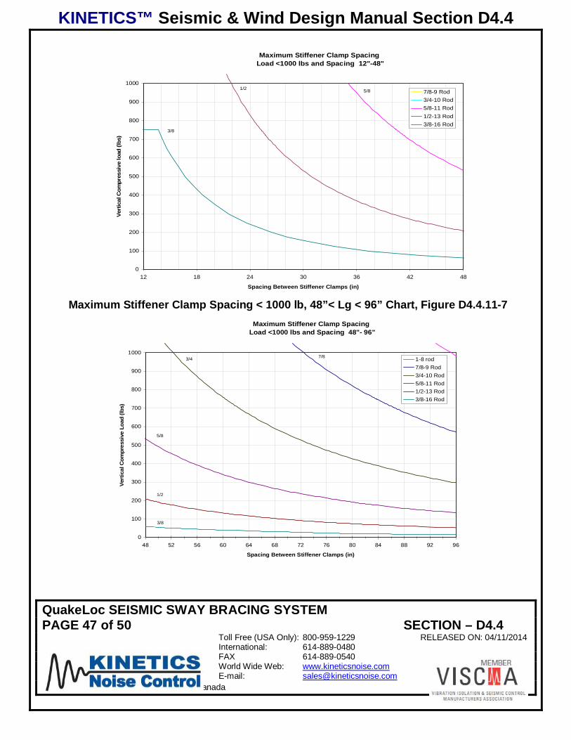
KINETICS™ Seismic & Wind Design Manual Section D4.4
QuakeLoc SEISMIC SWAY BRACING SYSTEMPAGE 47 of 50 SECTION – D4.4
Toll Free (USA Only): 800-959-1229 RELEASED ON: 04/11/2014International: 614-889-0480FAX 614-889-0540World Wide Web: www.kineticsnoise.comE-mail: [email protected]
Dublin, Ohio, USA Cambridge, Ontario, Canada
Maximum Stiffener Clamp Spacing Load <1000 lbs and Spacing 12"-48"
0
100
200
300
400
500
600
700
800
900
1000
12 18 24 30 36 42 48
Spacing Between Stiffener Clamps (in)
Vert
ical
Com
pres
sive
load
(lbs)
7/8-9 Rod3/4-10 Rod5/8-11 Rod1/2-13 Rod3/8-16 Rod
3/8
1/2 5/8
Maximum Stiffener Clamp Spacing < 1000 lb, 48”< Lg < 96” Chart, Figure D4.4.11-7Maximum Stiffener Clamp Spacing
Load <1000 lbs and Spacing 48"- 96"
0
100
200
300
400
500
600
700
800
900
1000
48 52 56 60 64 68 72 76 80 84 88 92 96
Spacing Between Stiffener Clamps (in)
Vert
ical
Com
pres
sive
Load
(lbs)
1-8 rod7/8-9 Rod3/4-10 Rod5/8-11 Rod1/2-13 Rod3/8-16 Rod
3/8
1/2
3/4
5/8
7/8
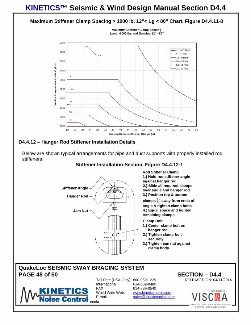
KINETICS™ Seismic & Wind Design Manual Section D4.4
QuakeLoc SEISMIC SWAY BRACING SYSTEMPAGE 48 of 50 SECTION – D4.4
Toll Free (USA Only): 800-959-1229 RELEASED ON: 04/11/2014International: 614-889-0480FAX 614-889-0540World Wide Web: www.kineticsnoise.comE-mail: [email protected]
Dublin, Ohio, USA Cambridge, Ontario, Canada
Maximum Stiffener Clamp Spacing > 1000 lb, 12”< Lg < 80” Chart, Figure D4.4.11-8Maximum Stiffener Clamp Spacing
Load >1000 lbs and Spacing 12" - 80"
1000
2000
3000
4000
5000
6000
7000
8000
9000
10000
12 16 20 24 28 32 36 40 44 48 52 56 60 64 68 72 76 80
Spacing Between Stiffener Clamps (in)
Vert
ical
Com
pres
sive
Load
sV F
(lbs)
1 1/4 -7 Rod1 - 8 Rod7/8 -9 Rod3/4 -10 Rod5/8-11 Rod1/2-13 Rod
1 1/4
1
7/8
3/4
5/8
1/2
D4.4.12 – Hanger Rod Stiffener Installation Details
Below are shown typical arrangements for pipe and duct supports with properly installed rodstiffeners.
Stiffener Installation Section, Figure D4.4.12-1
KNC
KHRC-B
Jam Nut
Rod Stiffener Clamp1.) Hold rod stiffener angleagainst hanger rod.2.) Slide all required clampsover angle and hanger rod.3.) Position top & bottomclamps 1
4" away from ends ofangle & tighten clamp bolts4.) Equal space and tightenremaining clamps.
Hanger Rod
Stiffener Angle
Clamp Bolt1.) Center clamp bolt on
hanger rod.2.) Tighten clamp bolt
securely.3.) Tighten jam nut against
clamp body.

KINETICS™ Seismic & Wind Design Manual Section D4.4
QuakeLoc SEISMIC SWAY BRACING SYSTEMPAGE 49 of 50 SECTION – D4.4
Toll Free (USA Only): 800-959-1229 RELEASED ON: 04/11/2014International: 614-889-0480FAX 614-889-0540World Wide Web: www.kineticsnoise.comE-mail: [email protected]
Dublin, Ohio, USA Cambridge, Ontario, Canada
Non-Isolated Single Hung Pipe Arrangement, Figure D4.4.12-2
Isolated Single Hung Pipe Arrangement, Figure D4.4.12-3

KINETICS™ Seismic & Wind Design Manual Section D4.4
QuakeLoc SEISMIC SWAY BRACING SYSTEMPAGE 50 of 50 SECTION – D4.4
Toll Free (USA Only): 800-959-1229 RELEASED ON: 04/11/2014International: 614-889-0480FAX 614-889-0540World Wide Web: www.kineticsnoise.comE-mail: [email protected]
Dublin, Ohio, USA Cambridge, Ontario, Canada
Trapeze Supported System with “Balanced” Restraints, Figure D4.4.12-4
Trapeze Supported System with “Offset” Restraints, Figure D4.4.12-5