kinematics ofcrystal growth in syntectonic fibrous · pdf filethe regional geological...
TRANSCRIPT
}oumul of Sr.uc/U,ul Gtology. Vol. 13. No, 1. pp. 823 10 836. 1991Printed in Great Britain
Kinematics of crystal growth in syntectonic fibrous veins
J. L. URAl·
Instituut voor Aardwetenschappen. P.O. Box 80021. 3508TA Utrecht, The Nelherlands
P. F. WILLIAMS
0191-3141191 $03.00+0.00© 1991 Pergamon Pre$S pic
Department of Geology. Universily of New Brunswick. Box 4400, Fredericton, N.B., Canada E3B SA3
and
H. L. M. VAN ROERMUNDt
InstituUl voor Aardwelenschappen, P.O, Box 80021, 3S08TA Utrecht, The Netherlands
(Received 21 Augusl 1989: occepled ill revi$id form 31 December 1990)
Abslnlct-Detailed obscrvationsof a set of fibrous antitaxial calcite veins in a slate reveal that some of the calcitefibres do not connect material markers on both sides of the vein and can therefore nOI have tracked the fullopening trajcelory during vein growth. This calls for a bellcr understanding of the mechanismsof fibre formationand reliable erileria to teSt the tracking hypothesis. Based on surface roughness characteristics of the vein wall wedevelop a simple model for shape·growth of crystals in a crack-scal environment which can account for bothtracking and non·tracking behaviours, and propose a set of 'tracking criteria' for antitaxial veins. Finally wediscuss ways by which Ihe model can be teSted against natural examples.
INTRODUCTION
SYNTECTONIC veins containing mineral grains with apronounced fibrous morphology are common in rocks atmetamorphic grades of greenschist facies and lower.They often occur together with veins which containmore equant infill morphologies, and are generally composed of calcite or quartz.
The fibrous morphologies are quite different fromwhat is expected for growth of these minerals in a fluidfilled cavity, where more equant growth habits aregenerally developed (Beach 1977).
Although it is not yet entirely clear how, repeatedcrack-seal events appear to play an essential role in theformation of fibrous morphologies, somehow interfering with the normal growth competition processwhich produces ingot textures and euhedral crystals(Grigor'ev 1965, Ramsay 1980, Cox & Etheridge 1983,van der Pluijm 1984, Cox el 01. 1986, Mawer 1987). Notethat in this paper we do not consider minerals whichdevelop fibrous habits when growing in a free fluid.
Durney & Ramsay (1973) recognized two main typesof crack-seal veins. In amitaxial veins crystal growthtakes place with the vein filling as a substrate, towardsthe wall rock, and on only one side of the crack. Insyntaxial veins crystals grow on the wall rock or fractured vein material, lowards the vein centre, on both
• Present address: KoninktijkefShell Exploratie en ProductieLaboratorium, P.O. Box 60. 2280 AS Rijswijk. The Netherlands.
tPresent address: Ecole Normale Superieure de Lyon. 46 AII~e
d·ltalie, 69364 Lyon C~dex 07, France.
sides of the crack. Which of the two mechanisms willoperate seems to depend mainly on material contrastbetween wall rock and vein material.
A striking feature of many vein fibres is their markedly curved shape, without the crystal lattice having thecorresponding curvature. This led Durney & Ramsay(1973) to propose that the curvature was developedduring crystal growth, with the fibre axis extendingparallel to the opening vector of the correspondingcracking event. This gave fibrous veins great promise asa tool for deciphering progressive deformation historiesin rocks, and at present fibres are a well established toolfor structural geologists (Ramsay & Huber 1983, p. 235,Beutner & Diegel 1985, Ellis 1986, Passchier & Urai1988).
Less attention has been paid to the tracking hypothesis itself, that is to ask questions like: do fibres track theincremental opening direction in all cases, by whatmechanism, how does their shape reflect opening histories, and what microstructural criteria are available totest the tracking hypothesis? This is in spite of theDurney & Ramsay (1973) and Cox & Etheridge (1983)papers where examples of non-tracking fibres were convincingly described. This was further substantiated byrecent papers (Cox 1987, Williams & Urai 1986, 1989)documenting more examples of veins where fibres didnot track the opening direction. As the veins describedby these authors have common morphologies, it ispossible that the observations have a more generalvalidity, casting doubt on results of earlier work wherethe tracking hypothesis was not tested.
The aim of this paper is first to give a detailed
823
824 J. L. URAl, P. F. WILLIAMS and H. L. M. VAN ROERMUND
description of a sel of veins in which some fibres showmicrostructures consistent with the tracking hypothesisbUI olhers have not tracked the full opening trajectory,and second to propose a simple model for crystal growthin a crack-seal environment which has the potential toexplain both Iypes of behaviour.
DATA
Sample description-macroscopic
In Ihis work we studied in detail a sel of veins takenfrom a slate quarry on the north side of highway #4 inNew York siale, 3 km southwest of the New YorkVermont border. The regional geological setting is in aninternally folded thrust slice, bounded by melanges ofthe Taconic thrust system (see Bosworth & Kidd 1985,and fig. 12 of Bosworth & Vollmer 1981 for an illustration of the large-scale structure). From the map ofBosworth & Kidd (1985) it can be seen that the quarry islocated on the normal limb of a tight to isoclinalsyncline-anticline pair. Passchier & Urai (1988) discussed an early set of veins from this outcrop. In thispaper we concentrate on second generation veins whichgrew during the later stages of deformation.
The samples investigated consist of a host rock of finegrained black slate, containing a series of quartz, calciteor mica rich layers, often less than I mOl thick. Theseprovide excellent markers for correlating material positions on either side of the veins. The rock is cut by up to5 mOl thick calcite veins, most of which are distinctlyfibrous in hand specimen. The plane containing thecurved fibres in most samples is approximately perpendicular to the intersection of bedding, cleavage and vein.
Thin sections were cut perpendicular to cleavage andcontain the plane of curved fibres as accurately as couldbe determined in hand specimen (wilhin a few degrees).They were doubly polished to thicknesses less than 10.urn and examined in transmiued light, cathodeluminescence (CL) and electron microscopy (backscatteredSEM and TEM). Observations pertinent to this studyare given below.
Microstructures
Most veins are fibrous in thin section, but in a numberof samples fibrous and blocky veins occur together.
Fibrous veiflS. These commonly display a well-definedmedian line (Durney & Ramsay 1973) defined by a thin
band of fine-grained calcite, second-phase particles, anda discontinuity in the CL intensity pattern .(Figs. 1-3).Calcite grains have dimensions of up toO.1 x 0.1 x 2 mOland locally extend from vein wall to vein wall (Figs. Ie &f and 3a). More frequently they are strongly elongate butdie out before reaching the other vein wall, locallybecause the fibre long axis is not exactly parallel to thethin section plane, or due to a discontinuity in themicrostructure (Figs. la-c and 3b) coincident with CLzonation. Fibre thickness is quite continuous along thelength of fibres which extend from wall to wall, but tendsto increase from the median line towards the vein wallacross the discontinuities mentioned above. Calcitegrain boundaries arc generally smooth and gentlycurved.
There are various heterogeneously distributed signsof crystal plastic deformation in some veins. Grains mayshow quite strong twinning and undulose extinction, thedev17lopment of subgrains and rare incipient formationof new grains by grain boundary migration which lendsto destroy existing CL zonations. These veins belong tothe first, more strongly deformed vein generation (Passchier & Urai 1988) with a more complicated structure.They are not discussed further in this paper. Some veinshave a composite structure, consisting of a deformedcore wilh an optically undeformed outer part (e.g. Figs.Ig and 4a). The majority of veins studied in this workcontain optically almost un deformed fibres with minortwinning.
Fibre curvature varies from sample to sample but isroughly consistent within each hand specimen. It isunrelated to optical deformation features. Fibres may becurved up to 900 without significant optically visibledeformation features.
In CL mode the veins show a well defined banding dueto discontinuities in CL intensity and colour. The banding is subparallel 10 the vein wall and symmetricallyarranged with respect 10 the median line (see Fig. I).Individual bands have shapes intermediate betweenthose of the median line and the wall rock. In a numberof examples smaller scale irregularities in wall rockshape are matched by similar irregularities in the CLbanding (Fig. ld). Discontinuities in CL intensity frequently correspond to sharp changes in fibre boundaryorientations, or to the discontinuous changes in fibrethickness described above.
Using the terminations of fine-scale lithological banding at the vein wall as markers, two different types ofveins can be distinguished: (i) veins in which fibres (orelongate grains) connect markers across a vein (Figs. Ie& f, 2a and 3c & d); and (ii) veins in which fibres do
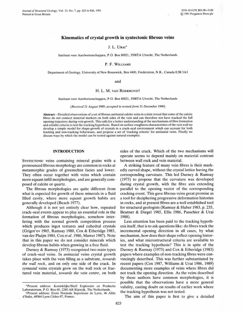
Fig. I, Transmillcd light (a. c. c. g) and CL (b, d. f. h) micrographs toshowvcin morphologies. (a) & (b) A fibrous vein showing growth zonationsymmctric aboutthc mcdian linc. Optically undeformed fibrcs changc thickness across CL discontinuities. Note that fibres do not accuratclyconncct markers (M) aeross thc vein. This vein is also shown in Fig. 2(a). The horizontal cdgc of caeh photograph is6.8 mm. (e) & (d) CL banding(B) mimicking small·scale irregUlarities in the wall rock. with fibres connecting corresponding markcrs. Note the trail of wall rock fragmentsincorporated in the vein (W). This vein is also shown in Fig. 2(a). The horizontal edge of each photograph is I mm. (c) & (f) Opticallyundeformed fibres connecting markers across a small \'cin. Notc the median line marked by CL contrast. and the thin quartz-<:hlarite vein at thevein tip. containing isolated calcite grains. The horizontal edge of cach photograph is 1.6 mm, (g) & (h) A blocky vein with curved grainboundaries and CL banding similar to that in fibrous veins. Note the strongly twinned core overgrown by optically undeformcd rim. The
horizontal edge of each photograph is 0.7 mm.

Kinematics of growth in fibrous veins
Fig. 1

J. L. URAl, P. F. WILLIAMS and H. L. M. VAN ROEIl.MUND -
Fig. 2. (a) . (b) Micrognlphs showing \'cins in whieh fibres accuralelyconnect markers. logelher ..,dlh \'eins in ....-hieh fibresdo not connect markers. Vein A is shown in detail in Fig. l(a). \"I:in B in Fig. I(c) and \'ein C in Fig. l(e). The longedgc or
each photograph is 30 mm.

Kinematics of growth in fibrous veins
Fig. 3. (a) Fibrous vein showing eurved. oplically undcformed fibres eXlending from vein wall 10 vein wall. and a welldefined median line. The horizontal edge of the pholOgraph is 2.6 rnm. (b) Curved fibres changing lhickness across sharpbands. These usually correspond 10 CL eontrasl (d. Fig. 1). The horizontal edge of lhe photograph is 2.6 mm. (e) & (d)Veins with fibres connecling markers (0. T) across the vein. The horizontal edge of each photograph is 6.5 mm. (e) Vein inwhieh fibres connect one sel of markers (0) but fail to connect anolher SCI (T). The horizontal edge of the pholograph is 6.5
mm. (f) Vein in which fibres do not conneCl markers (0). The horiZOnlal edge of the photograph is 6.5 rnm.
827
J. L. URAl, P. F. WIl.LIAMS and H. L. M. VAN ROERMUND
,/'
f
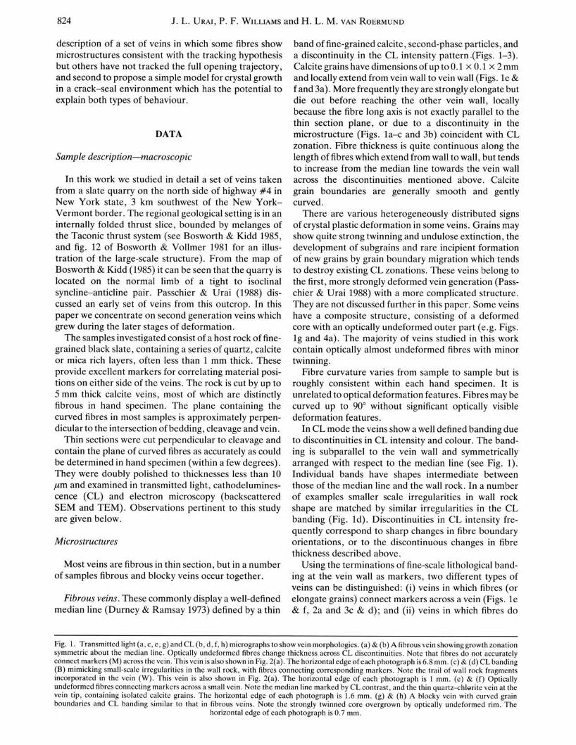
Fig. 4. (a) Vein with deformed, blocky core and fibrous rim. The horizontal edge of the photograph is I mm. (b) & (c)Caleite-quartz selvage boundaries. See text for explanation. The horizontal edge of the photographs is 0.3 mm. (d) TEMmicrograph of typical intrafibre dislocation substructure. showing isolated curved dislocations, loops and nodal points.
Scale bar is lJim.

Kinematics of growth in fibrous veins 829
not connect markers across the vein (Figs. la & b, 2a & band 3f), In both types, however. the sense of curvatureof the fibres is always consistent with the apparentdisplacement of the markers. Both types are found in asingle thin section, and even within a single vein (Figs. 2and 3e), (It should be noted here that in the photographsshown in Figs. I. 3 and 4 markers cannot always becorrelated uniquely across the vein. This correlation wasmade using whole thin section micrographs for allmarkers referred to in the figure captions.)
TEM observations were made on typical fibresextending from the median line to the vein wall, curvedapproximately 40" with minor undulose extinction (Fig.4d). The defect structure consists of minor e-twins. a fewfluid inclusions and the following dislocation substructure: curved free dislocations. dislocation loops andisolated nodal points. Preliminary contrast analyses reveal (1102) Burgers vectors. indicating most likely f- andr-slip ({IOTI}(IT02) and {0221}(lT02). respectively).Most of the dislocations can be shown to have climbedout of their glide planes. indicating dislocation creepprocesses. However, organized dislocation networksoccur only to a limited extent. Dislocation density isaround lOS cm-2. and fairly homogeneous over the fibrelength. Auid inclusions occur either along eo-twins andisolated dislocations or as isolated bubbles. sometimesarnlOged in lines.
'Blocky' .'ei"s. About 20% of the veins studied contain largc. more or Icss cquant calcite crystals. givingthem a blocky appearance. Veins changing laterallyfrom fibrous to blocky. and veins with a blocky coreovcrgrown by a fibrous outer part (Fig. 4a) arc foundlocally. In a number of blocky veins grain bO/lluJarieshave idcntical curvaturcs to fibre boundaries in thc samcsample (Figs. Ig & h). In addition. CL pallerns of bothfibrous and blocky vcins are very similar, showing thesame banding symmetrical about a median line withcomparable sequences of intensity changes.
GrOIVlh ,flIr[ace morphology. All veins show a thinquartz-chloritc selvage between the calcite and the slatewall rock (see Figs. 4b & c). similar to the ones describedin Ramsay & Huber(1983) and Williams & Urai (1989).Wherever small wall rock fragments are enclosed incomplex veins initially consisting of more than onebranch (as shown by CL zonation), the fragments havean identical quartz-chloritc selvagc. In sharp vein tipsthe selvage from both sides of the vein coalesces into athin. syntaxial quartz-chlorite vein approximately alongthe extension of the median line. containing occasionalisolated calcitc grains (Fig. Ie). Identical quartzchlorite veins also occur unconnected to calcite veins in anumber of cases (e.g. Fig. 2a).
At higher magnification. the quartz-chlorite selvage isoften fibrous. with the fibres at a high angle to the veinwall. increasing in width toward the \'ein cenler. Theboundary of the selvage with the calcite vein fill isirregular in shape. down to the submicron scale. Theboundary gencrally has a dominant wavelength com-
poncnt of the same order of magnitude as the fibrediameter. and is generally non-interlocking with the veinmaterial. When examined in detail, the fibre boundariesshow a tendency to be located near points in this boundary which arc closest to the median line.
INTERPRETATION OF THE MICROSTRUcrURES
Following normal practice (e.g. Richter & Zinkernagel 1981, Dietrich & Orant 1985. MacheI1985. Solomon1989) we intcrpret the bands of CL discontinuities asmarking traces of a growth surface at successive growthincrements. thc differences in CL intensity being dueeither to changes in the geochemistry and temperatureof the fluid (cf. Rye & Bradbury 1980). or to variation incrystal growth rate (ten Have & Heynen 1985). Both thesymmetrical CL banding and the fibres extending acrossthe median line are good evidence for antitaxial accretion of the veins. with simultaneous growth of all fibresfrom the median line towards the vein wall, and fracturing and growth at the quartz selvage-vein contact. Thesymmetry in the CL band shows that mean rates ofaccretion at opposing boundaries were more or lessequal. and that the vein aspect ratio generally decreasedduring vein accretion. (Note that no information ispresent on the time-continuity of opening. and the veinsmay well have opened during several distinct periods offluid movement. separated by periods of deformationwithout vein accretion.)
The :lvailable evidence suggests that a large part of thequartz-chlorite selvage grew syntaxially from the slatesurface III an cmly stage of vein development. withpossible additional growth at a later stage. On the otherhand. the absence of calcite in the country rock aroundmost veins suggests that calcite growth started with anucleation stage. The difference between blocky andfibrous caldtc morphologies may thcn bc either due todifferences in nucleation rates (producing differences ininitial calcite grain size). or to the presence or absence ofisolated fructure arrays during the initial opening stagc(cf. Fig. Ie). the size of which dctermined the initialcalcite grain sizc and shape.
As argued by Pllsschier & Unli (1988), vein accretiontook place in a rock which was undergoing strongly noncoaxial deformation. The growing veins were rotatingwith respect to the instantaneous stretching axes. anddepending on local variations in wall rock strengths,some veins could have deformed internally at differentstages of growth. This agrees with some veins having adeformedcentcr. O\'ergrown by an undeformed rim. andis also supported by the TEM observations. Theseindicate plastic deformation of the fibres with lowoverall strains (less than a few per cent).
Optically continuous fibres with a curved shape can beformed by one or a combination of the following processes (see Williams & Urai 1989): (i) growth in a curvedshape; (ii) plastic deformation of initially straight or lesscurved fibres; or (iii) process (ii). followed by grainboundary migration recrystallization. Williams & Urai
Kinematics of growth in fibrous veins 831
B, B2
VEIN
B3
VEIN
B1 B2 B3
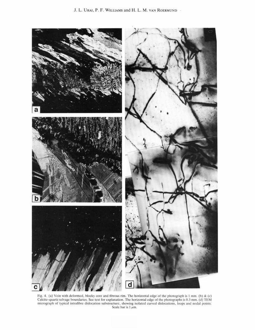
Fig. 5. An illu~lralion of grain boundar)' prop~lgMion in ;In ;lnlil;lxi;ll eraek--.c,,1 win. a'~lImll1g l"oIltropie gm" th kin("tics.(~I) Imm("di;lh:ll' ~lfter a cracking C\'ent (opening \'eetor marked by" hite arrow). The "'all rock-nuid interface i~ defined b>'the t"o planar Ketion~ A-B-C. Three representative grain bound;!rie, in the \'ein material ;!r(" marked Ill. 112 and lB.(b) During th(" fir~t K,L1ing ewnt. the gro"'th surface has propagated equal di~t,lOeese\ery" lIere. Therefore the lilree grainbou"darl("s exwnd perpendicul;lr to the growth surface. The grey line indicate' lhe initial er<lel< 'urf"ee. ,md the thin blackline marks lhe po"ition of Ihe growlh surbee at ~111 earlier st;lge, (c) Sc"ling i~ alm~e complete. BI and 83 ha\e propagatedperpendieul~!rIOlhc growlh ,urf'Lce. but B2 has reached the eorn..:r in tile gro"tll ,urfae..: and IIm,t frolllthen on propagate"long lhe hi-eetrix ofthc 1>Cgments u11lilthe end of this seal ev..:nl. (d) After tllr..:c complct("d crack....e.,l cv..:11ls. Note 1I0w H2II~" ,tart..:d prop~!gating pcrpendicular to the groweh surface;u the hcginning of (""ch _eahng ("\ent. and cOn1inued along Ihe
hiscctrix of lile scgme11ls ..fler rc;!ching the lOOTIler in the gro" lh ~Llrfaee.
The procedure for the simulations is as follows, Firstone defines a median line. the wall rock boundarydefined by a series of connected line segments. and anopening trajectory defined by a series of vectors. Then anumber of grain boundaries arc defined. connecting themedian line and the wall rock boundary. The wall rockboundary is translated by the first opening trajeclOryvector. and the grain boundaries extended to 'fill thegap' following the rules outlined above. This process isrepeated for all vectors of the opening trajectory. Notethat we do not .1Itempt 10 model the nucleation stage ofthe vein fill: the starting grain boundary configurationsin the simulations arc chosen arbitrarily. An infinite
number of starting grain boundary configurations arcpossible with a given wall rock shape.
The simulations arc characterized by the followinggeometrical elelllellls (Fig. 6): opening increlllent lengthx. the wavelength A. and amplitude y of crack irregularities. and the angle a bel ween the incremental opening vector and the local orient.lIion of Ihe crack surface.In addition we define fJ as 2 arctan(/.l2y). V;lriations inthese parameters determine fibre morphology. Forexample. in Fig. 6(c) y is decreased by a factor 3. in asituation otherwise identical to Fig. 6(b). It can be seenthat although the fibrous shape is still maintained andthe fibre long axis is slightly oblique to the enveloping

832 J. L. URAl, P. F. WILLIAMS and H. L. M. VAN ROERMUND
b
A'
I~I
f
openingtrajectory
growthincrement
MEDIAN LINE
r.mJm:l:.---_.
c
a
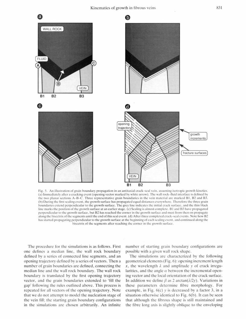
eFig. 6. Results of sirnul:lIions of the development obntilaxial veins. using the model described in the texl. (a) Vein growthin a planarCr:lck. Note Ih11l fibres liTe sWlight irrcspel;li\'c of lhe shape of the opening trajectory. (b) The S111l1C situation as in(:1). but wilh an irregular crack surface (A-A '), showing the growth of cun'cd fibres which track the op.::ning trajectory. Theinsert shows the geometrical c1cmC1llS discussed in lhe lext. (c) As in (b) hUI wilh a lower \:duc of>, (:Implitude of crackirrcguillrilics). Note that fibres do nOllrack the opening trajectory. (d) As in (b) but wilh a larger \'alue of xli.. Note thatfibres do nOllrack the opening lrajectory. (c) Erfect of more complicaled cr:lck ~hupes. NOle that fibres truck the openinglrajectory. :llld th~t' fibre boundaries lend 10 follow depressions in the growlh surf~tcc. (f) Efkel of a second wavelcngthcomponent (of lhe order of x) in the crack surfacc. NOle lhal the lcndeney for fibre bound;trics to be localcd ncar the main
depre~sions in the growth surface bo::comes Ic~s.

Kinematics of growth in fibrous veins 833
FLUID
the tracking efficiency quickly decreases to values wellbelow I.
Figure 6(e) further illustrates the consequences ofmore complicated crack shapes on fibre morphology. Anumber of aspects can be noted. First. as already seen inFig. 6(a). grain boundaries have the tendency to growtowards the local depressions in the growth surface, (Le.points closest to the median line). TIlis means that in thecase of a sufficiently fine-grained initial vein. a certainamount of growth selection may take place without thepresence of anisotropic growth kinetics, the dominantfibre size being determined by the wavelength ).. If theinitial crystal size is larger than )., no increase of fibrethickness is possible. but the grain boundaries will propagate following the same rules as described above. Forsufficiently large starting grain diameters blocky grainswith their boundaries along the opening trajectory maybe formed (cf. Fig. Ig).
In the case of more complicated natural crack geometries the wavelength). cannot be simply defined. However, from Fig. 6 it is clear that irregularities with awavelength smaller than x will not have a noticeableeffect on grain boundary propagation. Here for practicalpurposes). can be taken at about lOOx. This is furtherillustrated in the simulation of Fig. 6(£), where the fibreboundaries follow second-order irregularities in thecrack surface.
A further necessary condition for the simulation towork is that the crack can be opened without the two
Fig. 8. Simulation similar to those in Fig. 6. but "'ith one sectionwhcre vein and wall rock have interlocking shapes. (a) During thecrack e\'entthe \'ein is fractured along A-B and in this section the crackis scaled by gro"'th from both sides of (he erack. Assuming the samerules as defined in Fig. 5 for both surfaces. and repeated fracturingalong A-B. the resulting vein morphology is shown in (b). Brokenlines indicatc hcaled cracks in the fibre (in nalllre possibly marked bynuid inclusion trails). Notc the smldl steps in the fibre boundary: these
have alrcady been de.seribcd by Cox & Etheridge (1983).
10080
bFig. 7. (a) Tracking efficiency as a function of« and fJ. The insertshows the dcfinitions of (l and fl. (b) Cartoon illustrating the definition
of tracking cfficiency £,. See text for explanation.
surface of the crack. the fibre docs not track the opcningtrajectory. It is easily verified that in this case the maingeometrical factor determining 'tracking efficiency' isthe angle a bctween the incremental opening vector andthe local orientation of the crack surface.
Another important factor in the model is illustrated inFig. 6(d). Here we use the same crack shape and openingtrajectory as in Fig. 6(b), but with a larger incrementlength x. It can be seen again that the fibres do not trackthe opening trajectory. The important parameter here isthe ratio of the wllVelcngth of the crack irregularities tothe increment length, xf)•.
In summary. the model predicts, somewhat loosely. a'tracking criterion' given by: a >90" and x «k If thiscriterion is not met. fibres will track the opening direction only partially. We define tracking efficiency E( of afibre as £,=xrlxon . where Xf is the vein parallel displacement recorded by the fibre and X m is the vein-parallelcomponent of the net opening vector. For a simplesymmetric crack geometry E( can be expressed as afunction of the angles a and pfor x«).. Figure 7 is a plotof £t as a function of a. for different values ofp. It can beseen that even for reasonably rough surfaces, at a <9<r
1.0
~>- 0.80zwU 0.8
"'..w"z 0.4i: 1200
"a: 130... 0.2140
160 1500.0
0 20 40 60
a Cl
Kinem,lIics of growth in fibrous veins 835
examined by us to date, where suitable markers werepresent, this indeed seems to be the case. Fibres changing thickness during vein accretion (e.g. Fig. 3b) can beexplained by the model by assuming changes in the crackshape during vein accretion. possibly by a stage ofrenewed growth of the quartz--ehlorite selvage.
Veins opening with nat crack surfaces (d. Fig. 6a)provide another situation against which the model canbe tested. For example, fibrous quartz is frequentlyfound in pressure fringes around euhedral pyrite crystals(Spry 1969. White & Wilson 1978. Ramsay & Huber1983, p. 265). Here it is commonly inferred that accretion occurs at the quartz-pyrite interface, and fibresgrow perpendicular to the pyrite faces. producing 'facecontrolled' fibres (fig. 14.10 in Ramsay & Huber, 1983).Using our model to simulate this situation (Fig. 10) it canbe seen that depending on the presence of a rotationalcomponent in the motion of the wall rock with respect tothe pyrite crystal, it predicts either straight or curvedfibres growing perpendicular to the groM" slirface (seealso Cox & Etheridge 1983). The model also predictsthat the difference between 'face-controlled' and'displacement-controlled' fibre morphologies (Ramsay& Huber 1983, p. 268) will be determined by the pyritesurface morphology.
At this stage we examine the assumptions of themodel in more detail.
Assumption (1): cracks are filled completely before thenext cracking event. In the absence of second-phaseinclusion trails (see Ramsay 1980) we do not have anydirect evidence for a crack-seal mechanism of accretionin the veins studied. Assumption (I) is certainly notalways valid in nature. for example Fisher& Byrne (I 990)described veins in which only pan of the fibres grew fastenough to seal the crack in each event, and the spacebetween these crystals was filled later by slower growingcrystals. When assumption (I) is relaxed, the model canstill generate fibrous morphologies with straight, nonparallel grain boundaries, but with fibres growing independently of the opening trajectory. Note however that acrack-seal process is thought to be essential in maintaining assumption (2). as explained below.
Assumption (2): crystal growth rates are isotropic.If a single crystal with smooth but arbitrarily cut(irrational), surfaces is placed in a slightly supersaturated solution, growth of this crystal can occur in twodifferent ways (Bennema 1974. Sunagawa 1982, Bennema & van der Eerden 1987. (a) The initially smoothsurface is gradually coarsened, and becomes covered byslow growing F faces (Hartman 1973). This anisotropicgrowth will result in F faces gradually determiningcrystal morphology: this is the commonly observed process by which euhedral crystals grow from solution.Growth mechanisms on these F faces arc spiral growth atscrew dislocation terminations or two-dimensional nucleation. (b) Above some critical value of temperaturethe nat faces undergo the so-called roughening transition (Bennema 1974). Under these conditions theformation of nat faces is not possible. and growth ratesbecome a linear function of supersaturation (Nielsen &
Toft 1984), the rate-limiting step being diffusion throughthe boundary layer.ll the crystal-fluid interface. Growthrates above the roughening transition tend to be isotropic, producing subspherical crystals.
In terms of crystal growth mechanisms. the fundamental difference between a crack-seal process andgrowth from a free fluid is that at the end of each crackseal increment the crystals arc forced to assume the(irrational) shape of the wall rock. As a consequence.growth in each seal event stans along these surfaces.These can in general be considered crystallographicallyrough, that is with a large density of .1I0mic scale kinkson the surface.
Under the hydrothermal growth conditions considered, quanz and calcite growing in a free fluid tend tobecome euhedral. However. the fresh fracture surfacesafter each cracking event can be considcred rough untilthe first segments with F faces arc formed on them. Asshown by inclusion band separations. typical incrementlengths in crack-seal veins are between 0.01 and 0.1 mm(Ramsay 1980, Cox 1987). Unfortunately no experimcntal or theoretical data are available on the rate at whichrough faces become segmented. but it is reasonable toassume that for opening increments of up to a fcw tcnthsof microns the roughness of the growth surface will bemaintained by the crack-seal mechanism. This will result in isotropic growth kinetics under conditions wherethis would not be predicted from conventional crystalgrowth considerations.
On the other hand, if the growth surface is notgrowing fast enough to seal the crack after each crackevent, due to small differences in vein opening vs crystalgrowth rates, this may result in the switch betweenfibrous and euhedral. blocky veins (cL Mawer 1987).
Assumption (3): the model is two-dimensional.Three-dimensional simulations using assumptions (1)and (2) are beyond the scope of the present study.However in the case of a symmetrical egg-box shapedwall rock-vein contact it can be quite easily "erified thatthe same principles as derived in Fig. 10 will hold ingeneral. In addition, the three-dimensional morphologyof the growth surface has one essential property which ismissing in our two-dimensional model. For crystalgrowth from a solution one has to assume fluid transportalong the growth surface in order to deposit enough veinmaterial to seal the crack. In Fig. 5 it can be seen thatwhen the growth surface reaches the vein wall. no moretransport along the growth surface is possible. In Ihethree-dimensional situation however. fluid transport isexpected to occur at a much later stage with transportalong a complex tortuous path.
CONCLUSIONS
Evidence for fibres having tracked the opening trajectory is provided by:
-optically undeformed primary fibres conncctingmarkers across the vein;
-intermediate positions of the wall rock marked byCL or inclusion bands:
836 J. L URAl, P. F. WILI.IAMS and H. L. M. VAN ROERMUND
-microstructural evidence for localized cracking andaccretion.
The absence of any of these Jines ofevidence may leadto large errors of interpretation. We suggest that fibrousveins should be studied carefully before attempts arcmade to deduce progressive deformation hislOries fromfibre shapes.
A simple model, assuming crack-scal accretion andiSOIropic growth kinetics is capable of explaining therange of presently documented fibrous vein microstructures.
Ackllowledgemeflls-We thank P. Hariman S. F COlt, W. D. Means.M. Ellis. C. Wocnsdrcgt and E. van dcr Voorl for illuminatingdiscussions on crystal growth and on "cin fibres. and for thoughtfulreviews which much impro\'cd the manuscript. Financial support to J.L. Urai from a C & C Huygens fellowship of The NetherlandsOrganization for the Advancement of Pure Rescarch (NWO) isgratefully acknowledged. P. F. Williams was supported by a NationalSciences and Engineering Rescarch Council (NSERC) OperatingGrant. Electron microscopy ....as carried out at the EM facilities atUtrecht supported by NWO.
REFERENCES
Beach. A. 1977. Vein arrays. hydraulic fractures and pressure solutionstructures in a deformed flysch sequence. S. W. England. TOC/QIIOphysics 40. 201-225.
Bennema. P. 1974. Crystal growth from solution-theor)' and experiment. J. Crystal Growth 24/25. 76--83,
Bennema. P. & Eerden.J. P. van der 1987, Crystal graphs, Connectednets. roughening transition and the morphology of crystals, In:Morphology of Crystals, Pari A (edited by Sunaga....a. I.). Terrapublications. Tok)'o, 1-75.
Beutner. E. C. & Diegel. F. A. 1985. Determination of fold kinema·tics from syntectonic fibres in pressure shadows. Martinsburg slate.New Jersey. Alii. J. Sci, Z85. 16-50.
Bosworth. w. & Kidd. W. S. F. 1985. Thrusts. melanges. foldedthrusts and duplexes in the Taconic foreland. In: N/,,.. York StaleGeological AssocillliOl/ 57th All/wal Muting Field Trip Gllidebook(edited by Lindemann. R.). Skidmore College. Saratoga. NewYork.
Bosworth. W. & Vollmer. F. W. 1981. Structures of the medialOrdovician flysch of Eastern New York: Deformation of synorogenic deposits in an o\'erthrust cnvironment. J. Geol. 89. 551-568.
Cox. S. F. 1987. Antitaxial erack--scal vcin microstrueturcs and theirrelationship to displacement paths. J. StrllCI. G/'ol. 9. 779-787.
Cox. S. F. & Etheridge. M. A. 1983. Crack--scal fibre growth mechanisms and their significance in the development of oriented layersilicate microstructures. Tec/Qnophysics 92. 147-170.
Cox. S. F. Etheridge. M. A. & Wall. V. J. 1986. The role of fluids insyntectonic mass transport and the localization of metamorphic\·ein.type ore deposits. Ore Geol. Rev, 2.65-86.
Dietrich. D. & Gram. 1'. R. 1985. Cathodeluminescencc pctrographyof syntectonic quartZ fibrcs. J. StrllCI. Gml. 7. 541-553.
Drury. M. & UraL J. L. 1990. Deformation related recrystallizationprocesses. Teclonopl/ysics 172. 235-253.
Durney. D. W. & Ramsay.J. G. 1973. Incremental strains measuredby syntectonic crystal gro,",'ths. In: Grm'ity fmd TI'C/Qlrics (edited byDe Jong. K. A. & Scholten. R.). John Wile)'. New York. 67-96.
Ellis, M. 1986. The determination of progressive deformation historiesfrom antitaxial syntectonic crystal fibres. J. Strllct. Geol. 1:1. 701-709.
Fisher. D. & Bryne. T. 1990. The character and distribution ofmineralized fracturcs in the Kodiak formation. Alaska: Implicationsfor fluid flow in an underthrust sequence. J. geophys. Res. 95 (86).9069-9080.
Grigor'ev, D, P, 1965. Oll/ogeny of Minerals. S. Monson. Jerus,1Iem.Guillopl!. r-,·I. & Poiricr. J. P. 1979. D)'namic recrystallization during
Heep of single crystalline halite: an experimental study. J. geophYs.Res. 84(810), 5557-5567.
Hartman. P. 1987. Modern PBC theory. In: Morphology 0/ Crystals.I'lm A (edited by Sunagawa. I.). Terrapublications. Tokyo. 269319.
Hal'e. T. ten & Heynen. W. M. M. 1985. Cathodeluminescenceactivation and zonation in carbonate rocks: :m experimcntalapproach. Geologie Mij,rb. 64. 297-310.
Machel. H. G. 1985. Cathodeluminesccncc in calcite and dolomite andits interpretation. Geosci. Call. 10. 139-147.
Mawer. C. K. 1987. Mech;mics of formation of gold-bearing quartz"eins. Nova Scotia. Canada. T/'clOl/ophysics U6. 99--119.
Nielsen. A. E. & Toft. J. M. 1984. Electrolyte crystal growth kinetics.J. CrysltJl GrowlII 67.278-288.
O·Hanley. D. S. 1987. Dcformation-free growth of NaCI cross-fiber"eins: implications for syntectonic growth. Geol. Soc. Am. Abs. w.I'rog, 19.237.
Passchier. C. W. & Urai. J. L. 1988. Vorticity and strain analysis usingMohr diagrams. J. SlruCt. G/'ol. 10.755-763.
Pluijm. B. A. van der 1984. An unusual 'crack-scal" vein geometry.J. SImer. Geol. 6. 593-597.
Rams,1Y, J, G. 1980. The crack--scal mcchanism of rock deformation.Nalllrt' 284. 135-139.
Ramsay. J. F. & '·Iuber. M. I. 1983. Th/' T/'dl/liqlles of ModernStrllCllIral Geofogy, Volullle I: S,m;,/ Analysis. Academic Press.London.
Richter. D. K. & Zinkernagel. U. 1981. Zur Anwendungder Kathodoluminescenz in der Karbonatpetrographie. Geol. Rdsch. 70.1276-1302.
Rye. D. M. & Bradbury. H. J. 1988. "1uid Itow in the crust: ancxample from a Pyrenean thrust n1mp. Alii. J. Sci. 288. 197-235.
Solomon. S, F. 1989. The early diagcnetic origin of lower Carboniferous mottled limestones (pscudobreccias) SI'tlim/'ll/ology 36. 399418.
Spry. A. 1969. Metamorplric Te;rfllres. I'ergamon Press. Oxford.Sunagawa. I. 1982, Morphology of Cr)'stals in rclation to growth
conditions. £swfJios Geol, 38. 127-1J.J.White. S. H. & Wilson. C. J. L. 1978. Microstructure of some quartz
pressure fringes. Nl'lIl'sJb. Miller. Ablr. 134.33--51.Williams. P. F. & Urai, J. L. 1986. Curved "ein fibres: all alternati\'e
explanation. (Abs.). huema/iOlral COII/ereIICt 0/1 TeclOllic andS/mCfllral Processes. Utrecht.
Williams. P. F. & UraL J. L. 1989. Curved vein fibres: an altcrnati\'cexplanation. Tf'C/OIIOJ!llysics 158. 311-333.

