kinematics 3: kinematic models of sensors and …introduction to mobile robots kinematics 3:...
TRANSCRIPT

Introduction to Mobile RobotsKinematics 3: Kinematic Models of Sensors and Actuators
1
Alonzo Kelly Fall 1996
Kinematics 3: Kinematic Models of Sensorsand Actuators

Introduction to Mobile RobotsKinematics 3: Kinematic Models of Sensors and Actuators
21.1Axis Conventions
Alonzo Kelly Fall 1996
1 Vehicle Attitude in Euler Angle Form1.1 Axis Conventions
• In aerospace vehicles, z points downward. Good for airplanesand satellites.• Here z points up, y forward, and x out the right side. This hasthe advantage that the projection of 3D information onto the x-y plane is more natural.• The convention used herecorresponds to a z-x-y Euler anglesequence.• It is not advisable to use the homogeneous transformsdeveloped here until they are verified to be correct for anysensors and actuators that are used.
1.2 Frame Assignment
• Some common frames are indicated in the figure below:
yb
yb
zb
xb
yn
zn
yn
xn
yh
zh
ys
zs
yh,sxh,s
yw
zw
ywxw
yp
zp
yp
xp

Introduction to Mobile RobotsKinematics 3: Kinematic Models of Sensors and Actuators
31.2Frame Assignment
Alonzo Kelly Fall 1996
1.2.1The Navigation Frame
• Coordinate system in which the vehicle position and attitudeis ultimately required.• “Normally”, The z axis is aligned with the gravity vector; they, or north axis is aligned with the geographic pole1; and the xaxis points east to complete a right-handed system.
1.2.2The Body Frame
• Positioned at the point on the vehicle body which is mostconvenient and is considered to be fixed in attitude with respectto the vehicle body.
1.2.3The Positioner Frame
• Positioned at the point on or near any position estimationsystem which reportsits own position.• If the positioner system generates attitude and attitude ratesonly, this frame is not required because the attitude of thedevice will also be that of the vehicle.• For an INS, this is typically the center of the IMU and forGPS it is the phase center of the antenna2.
1.2.4The Sensor Head Frame
• Positioned at a convenient point on a sensor head such as:• the intersection of of rotary axes• center of mounting plate• optical center of the hosted sensor
1. The geographic pole is determined by the earth’s spin axis, not the magneticfield.2. The antenna may be nowhere near the GPS receiver.
Introduction to Mobile RobotsKinematics 3: Kinematic Models of Sensors and Actuators
41.3The RPY Transform
Alonzo Kelly Fall 1996
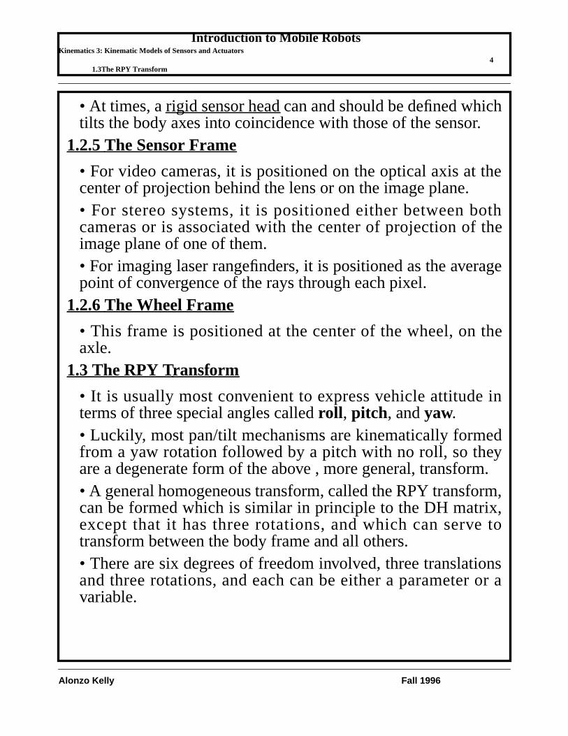
• At times, arigid sensor head can and should be defined whichtilts the body axes into coincidence with those of the sensor.
1.2.5The Sensor Frame
• For video cameras, it is positioned on the optical axis at thecenter of projection behind the lens or on the image plane.• For stereo systems, it is positioned either between bothcameras or is associated with the center of projection of theimage plane of one of them.• For imaging laser rangefinders, it is positioned as the averagepoint of convergence of the rays through each pixel.
1.2.6The Wheel Frame
• This frame is positioned at the center of the wheel, on theaxle.
1.3 The RPY Transform
• It is usually most convenient to express vehicle attitude interms of three special angles calledroll , pitch, andyaw.• Luckily, most pan/tilt mechanisms are kinematically formedfrom a yaw rotation followed by a pitch with no roll, so theyare a degenerate form of the above , more general, transform.• A general homogeneous transform, called the RPY transform,can be formed which is similar in principle to the DH matrix,except that it has three rotations, and which can serve totransform between the body frame and all others.• There are six degrees of freedom involved, three translationsand three rotations, and each can be either a parameter or avariable.

Introduction to Mobile RobotsKinematics 3: Kinematic Models of Sensors and Actuators
51.3The RPY Transform
Alonzo Kelly Fall 1996
• Let two general frames be defined as ‘a’ and ‘b’ and considerthe moving axis operations which transform frame ‘a’ intocoincidence with frame ‘b’.In order, these are:
• translate along the (x,y,z) axes of frame ‘a’ by (u,v,w)until its origin coincides with that of frame ‘b’• rotate about the new z axis by an angle calledyaw• rotate about the new x axis by an angle calledpitch• rotate about the new y axis by an angle calledroll
• Angles are measured counterclockwise positive according tothe right hand rule.• These operations are indicated below for the case oftransforming the navigation frame into the body frame.
• The forward kinematic transform that represents thissequence of operations is, according to our rules for forwardkinematics:
ψθφ
ya
ya
za
ψ
θ
xa
yb
xb
yb
zab
xa
za
xbzb
φ

Introduction to Mobile RobotsKinematics 3: Kinematic Models of Sensors and Actuators
61.3The RPY Transform
Alonzo Kelly Fall 1996
• This matrix has the following interpretations:• it rotates and translates points through the operationslisted, in the order listed, with respect to the axes of ‘a’.• its columns represent the axes and origin of frame ‘b’expressed in frame ‘a’ coordinates• it converts coordinates from frame ‘b’ to frame ‘a’
• Thematrix can be considered to be the conversion from apose vector of the form
to a coordinate frame.
Tba Trans u v w, ,( )Rotz ψ( )Rotx θ( )Roty φ( )=
Tba
1 0 0 u
0 1 0 v
0 0 1 w
0 0 0 1
cψ s– ψ 0 0
sψ cψ 0 0
0 0 1 0
0 0 0 1
1 0 0 0
0 cθ s– θ 0
0 sθ cθ 0
0 0 0 1
cφ 0 sφ 0
0 1 0 0
s– φ 0 cφ 0
0 0 0 1
=
Tba
cψcφ sψsθsφ–( ) s– ψcθ cψsφ sψsθcφ+( ) u
sψcφ cψsθsφ+( ) cψcθ sψsφ c– ψsθcφ( ) v
c– θsφ sθ cθcφ w
0 0 0 1
=
x y z θ φ ψT
Introduction to Mobile RobotsKinematics 3: Kinematic Models of Sensors and Actuators
71.4Inverse Kinematics for the RPY Transform
Alonzo Kelly Fall 1996
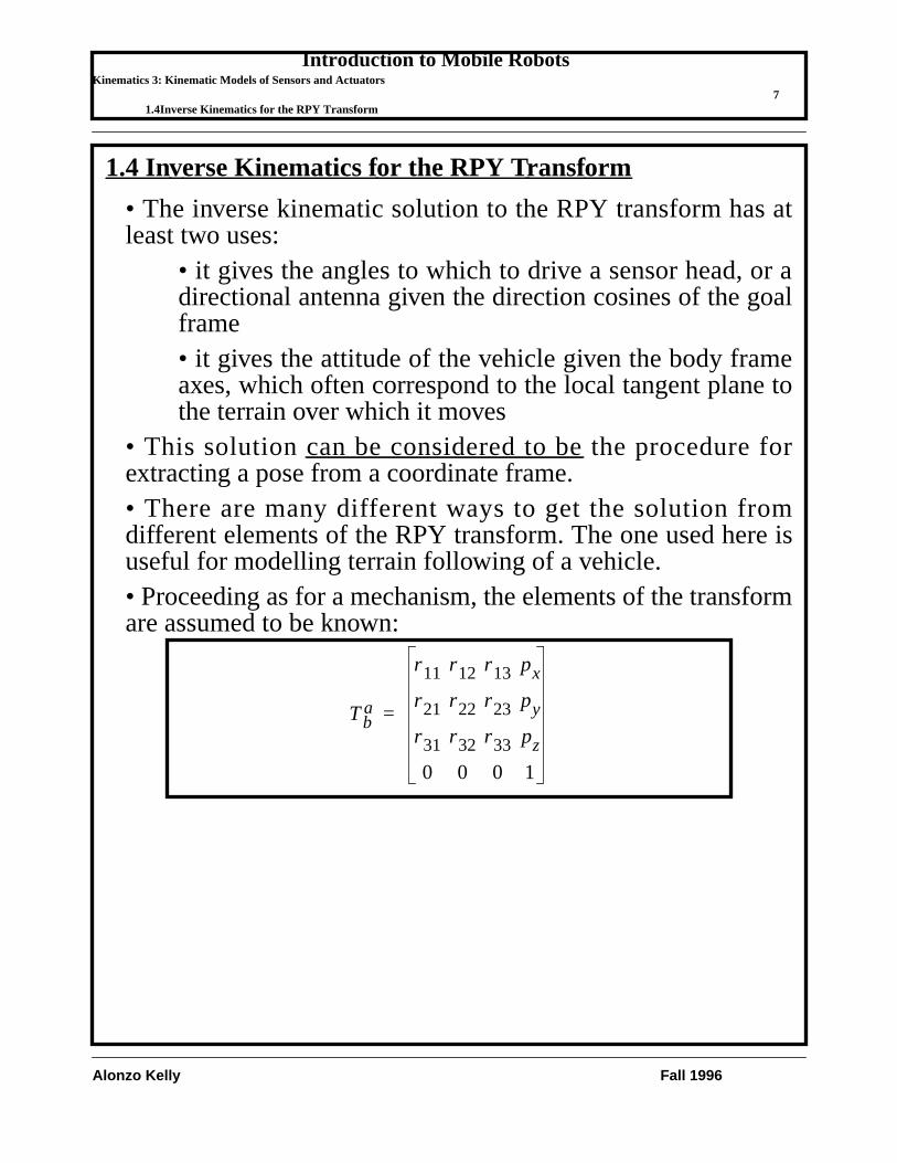
1.4 Inverse Kinematics for the RPY Transform
• The inverse kinematic solution to the RPY transform has atleast two uses:
• it gives the angles to which to drive a sensor head, or adirectional antenna given the direction cosines of the goalframe• it gives the attitude of the vehicle given the body frameaxes, which often correspond to the local tangent plane tothe terrain over which it moves
• This solutioncan be considered to be the procedure forextracting a pose from a coordinate frame.• There are many different ways to get the solution fromdifferent elements of the RPY transform. The one used here isuseful for modelling terrain following of a vehicle.• Proceeding as for a mechanism, the elements of the transformare assumed to be known:
Tba
r11 r12 r13 px
r21 r22 r23 py
r31 r32 r33 pz
0 0 0 1
=

Introduction to Mobile RobotsKinematics 3: Kinematic Models of Sensors and Actuators
81.4Inverse Kinematics for the RPY Transform
Alonzo Kelly Fall 1996
• The premultiplication set of equations will be used. The firstequation is:
• The translational elements are trivial. From the (1,2) and (2,2)elements:
• This implies thatyaw can be determined from a vector whichis known to be aligned with the body y axis. The secondequation is:
• which generates nothing new. The next equation is:• From the (3,3) and (3,2) elements:
Tba Trans u v w, ,( )Rotz ψ( )Rotx θ( )Roty φ( )=
r11 r12 r13 px
r21 r22 r23 py
r31 r32 r33 pz
0 0 0 1
cψcφ sψsθsφ–( ) s– ψcθ cψsφ sψsθcφ+( ) u
sψcφ cψsθsφ+( ) cψcθ sψsφ c– ψsθcφ( ) v
c– θsφ sθ cθcφ w
0 0 0 1
=
ψ 2 r22 r– 12,( )atan=
Trans u v w, ,( )[ ] 1– Tba Rotz ψ( )Rotx θ( )Roty φ( )=
r11 r12 r13 0
r21 r22 r23 0
r31 r32 r33 0
0 0 0 1
cψcφ sψsθsφ–( ) s– ψcθ cψsφ sψsθcφ+( ) 0
sψcφ cψsθsφ+( ) cψcθ sψsφ c– ψsθcφ( ) 0
c– θsφ sθ cθcφ 0
0 0 0 0
=
θ 2 r32 r– 12sψ r22cψ+,( )atan=

Introduction to Mobile RobotsKinematics 3: Kinematic Models of Sensors and Actuators
91.4Inverse Kinematics for the RPY Transform
Alonzo Kelly Fall 1996
• Which implies thatpitch can also be determined from a vectorknown to be aligned with the body y axis. A good solution for
is available from the (1,1) and (1,3) elements. However, forreasons of convenience, the solution will be delayed until thenext equation. The next equation is:• From the (1,1) and (3,1) elements:
• This implies thatroll can be derived from a vector known tobe aligned with the body x axis.
Rotz ψ( )[ ] 1– Trans u v w, ,( )[ ] 1– Tba Rotx θ( )Roty φ( )=
r11cψ r21sψ+( ) r12cψ r22sψ+( ) r13cψ r23sψ+( ) 0
r– 11sψ r21cψ+( ) r– 12sψ r22cψ+( ) r– 13sψ r23cψ+( ) 0
r31 r32 r33 0
0 0 0 1
cφ 0 sφ 0
sθsφ cθ s– θcφ 0
c– θsφ sθ cθcφ 0
0 0 0 1
=
φ
φ 2 sθ r– 11sψ r21cψ+[ ] r31cθ r11cψ r21sψ+( ),–( )atan=

Introduction to Mobile RobotsKinematics 3: Kinematic Models of Sensors and Actuators
101.4Inverse Kinematics for the RPY Transform
Alonzo Kelly Fall 1996
Rotx θ( )[ ] 1– Rotz ψ( )[ ] 1– Trans u v w, ,( )[ ] 1– Tba Roty φ( )=
r11cψ r21sψ+( ) r12cψ r22sψ+( )
cθ r– 11sψ r21cψ+[ ] r31sθ+ cθ r– 12sψ r22cψ+[ ] r32sθ+
sθ– r– 11sψ r21cψ+[ ] r31cθ+ sθ– r– 12sψ r22cψ+[ ] r32cθ+
0 0
cφ 0 sφ 0
0 1 0 0
s– φ 0 cφ 0
0 0 0 1
=
r13cψ r23sψ+( ) 0
cθ r– 13sψ r23cψ+[ ] r33sθ+ 0
sθ– r– 13sψ r23cψ+[ ] r33cθ+ 0
0 1
...........

Introduction to Mobile RobotsKinematics 3: Kinematic Models of Sensors and Actuators
2 Angular Velocity 111.4Inverse Kinematics for the RPY Transform
Alonzo Kelly Fall 1996
2 Angular Velocity• The roll, pitch, and yaw angles are, as we have defined them,measured about moving axes. Therefore, they are a sequence ofEuler angles, specifically, the z-x-y sequence1.• The Euler angle definition of vehicle attitude has thedisadvantage that the roll, pitch, and yaw angles arenot thequantities that are actually indicated by strapped-down vehicle-mounted sensors such as gyros.• The relationship between the rates of the Euler angles and theangular velocity vector is nonlinear. The angles are measuredneither about the body axes nor about the navigation frameaxes.• The total angular velocity is the sum of three components,each measured about one of the intermediate axes in the chainof rotations which bring the navigation frame into coincidencewith the body frame.
1. The sequence depends on the convention for assigning the directions of thelinear axes.
ωb0
φ̇0
rot y φ,( )θ̇0
0
rot y φ,( )rot x θ,( )0
0
ψ̇
+ +=
ωb
ωx
ωy
ωz
cφθ̇ sφcθψ̇–
φ̇ sθψ̇+
sφθ̇ cφcθψ̇+
cφ 0 s– φcθ0 1 sθsφ 0 cφcθ
θ̇φ̇ψ̇
= = =
Introduction to Mobile RobotsKinematics 3: Kinematic Models of Sensors and Actuators
2 Angular Velocity 121.4Inverse Kinematics for the RPY Transform
Alonzo Kelly Fall 1996
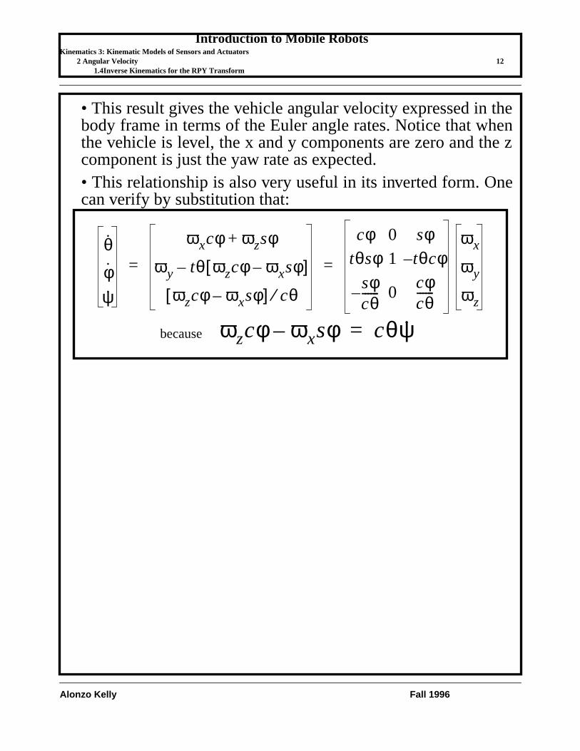
• This result gives the vehicle angular velocity expressed in thebody frame in terms of the Euler angle rates. Notice that whenthe vehicle is level, the x and y components are zero and the zcomponent is just the yaw rate as expected.• This relationship is also very useful in its inverted form. Onecan verify by substitution that:
θ̇φ̇ψ̇
ωxcφ ωzsφ+
ωy tθ ωzcφ ωxsφ–[ ]–
ωzcφ ωxsφ–[ ] cθ⁄
cφ 0 sφtθsφ 1 tθcφ–
sφcθ------– 0
cφcθ------
ωx
ωy
ωz
= =
ωzcφ ωxsφ– cθψ̇=because

Introduction to Mobile RobotsKinematics 3: Kinematic Models of Sensors and Actuators
3 Actuator Kinematics 133.1The Bicycle Model of Ackerman Steer Vehicles
Alonzo Kelly Fall 1996
3 Actuator Kinematics• For wheeled vehicles, the transformation from the angles ofthe steerable wheels and their velocities onto path curvatures,or equivalently angular velocities, can be very complicated.• There can be more degrees of freedom of steer than arenecessary. In this case, the equations which relate curvature tosteer angle areoverdetermined.
3.1 The Bicycle Model of Ackerman Steer Vehicles
• In one particular case, however, the steering mechanism isdesigned such that this will not be the case. This mechanism isused on most conventional automobiles and is calledAckerman steering.• It is useful to approximate the kinematics of the Ackermansteering mechanism by assuming that the two front wheels turnslightly differentially so that the instantaneous center ofrotation of the vehicle can be determined purely by kinematicmeans.• Let the angular velocity vector directed along the body z axisbe called . Using the bicycle model approximation, the pathcurvature , radius of curvature , and steer angle arerelated by the wheelbase .
β̇κ R α
L
1R--- αtan
L------------
sddβ= =
α
α
R
L

Introduction to Mobile RobotsKinematics 3: Kinematic Models of Sensors and Actuators
3 Actuator Kinematics 143.1The Bicycle Model of Ackerman Steer Vehicles
Alonzo Kelly Fall 1996
• Rotation rate is obtained from the speed as:
• Thus, the steer angle is an indirect measurement of theratio1 of to velocity through the function:
1. Curvature is . Dividing top and bottom by dt, its clear that curvaturealways measures the ratio of linear and angular velocities.
V
β̇sd
dβtd
ds κVVtαL
---------= = =
αβ̇
α Lβ̇V-------
atan κL( )atan= =
dβ ds⁄

Introduction to Mobile RobotsKinematics 3: Kinematic Models of Sensors and Actuators
4 Kinematics of Video Cameras 154.1Perspective Projection
Alonzo Kelly Fall 1996
4 Kinematics of Video Cameras• Many sensors used on robot vehicles are of the imagingvariety. For this class of sensors, the process of imageformation must be modelled.• Typically, these transformations arenot linear, and hence theycannot all be modelled by homogeneous transforms. Thissection provides the homogeneous transforms and nonlinearequations necessary for modelling such sensors.
4.1 Perspective Projection
• In the case of passive imaging systems, a system of lensesforms an image on an array of sensitive elements called a CCD.• These systems include traditional video cameras and infra redcameras.• The transformation from the sensor frame to the image planerow and column coordinates is the standard perspectiveprojection.• This type of transform is unique in two ways:
• it reduces the dimension of the input vector by one andhence it discards information• it requires a post normalization step where the output isdivided by the scale factor in order to re-establish a unityscale factor
Introduction to Mobile RobotsKinematics 3: Kinematic Models of Sensors and Actuators
4 Kinematics of Video Cameras 164.1Perspective Projection
Alonzo Kelly Fall 1996
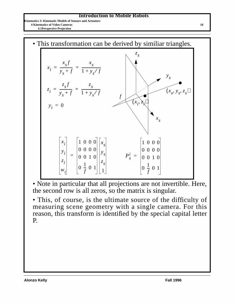
• This transformation can be derived by similiar triangles.
• Note in particular that all projections are not invertible. Here,the second row is all zeros, so the matrix is singular.• This, of course, is the ultimate source of the difficulty ofmeasuring scene geometry with a single camera. For thisreason, this transform is identified by the special capital letterP.
xi
xs f
ys f+--------------
xs
1 ys f⁄+---------------------= =
zi
zs f
ys f+--------------
zs
1 ys f⁄+---------------------= =
yi 0=
ys
xs
zs
xi
yi
zi
wi
1 0 0 0
0 0 0 0
0 0 1 0
01f--- 0 1
xs
ys
zs
1
=
fxs ys zs, ,( )
xi zi,( )
Psi
1 0 0 0
0 0 0 0
0 0 1 0
01f--- 0 1
=
Introduction to Mobile RobotsKinematics 3: Kinematic Models of Sensors and Actuators
5 Kinematics of Laser Rangefinders 175.1The Reflection Operator
Alonzo Kelly Fall 1996
5 Kinematics of Laser Rangefinders• Kinematics of reflecting a laser beam from a mirror arecentral to the operation of the current generation of laserrangefinders.• There are at least two ways to go to model them:
• The reflection operator• The “mechanism” forward kinematics where weconsider the operations on the laser beam to be themechanism.
• Always be careful to account formirror gain . This is theamount by which the rate of rotation of the laser beam isdifferent from the rate of rotation of the mirror.
5.1 The Reflection Operator
• This can be used when the translations of the laser beam canbe ignored.• From Snell’s law for reflection of a ray:
• The incident ray, the normal to the surface, and thereflected ray, all lie in the same plane.• The angle of incidence equals the angle of reflection.
• From these two rules, a very useful matrix operator can beformulated to reflect a vector off of any surface, given the unitnormal to the surface.• Consider a vector , not necessarily a unit vector, whichimpinges on a reflecting surface at a point where the unitnormal to the surface is . Unless they are parallel, the incidentand normal vector define a plane, which will be called thereflection plane.
vi
n̂
Introduction to Mobile RobotsKinematics 3: Kinematic Models of Sensors and Actuators
5 Kinematics of Laser Rangefinders 185.1The Reflection Operator
Alonzo Kelly Fall 1996
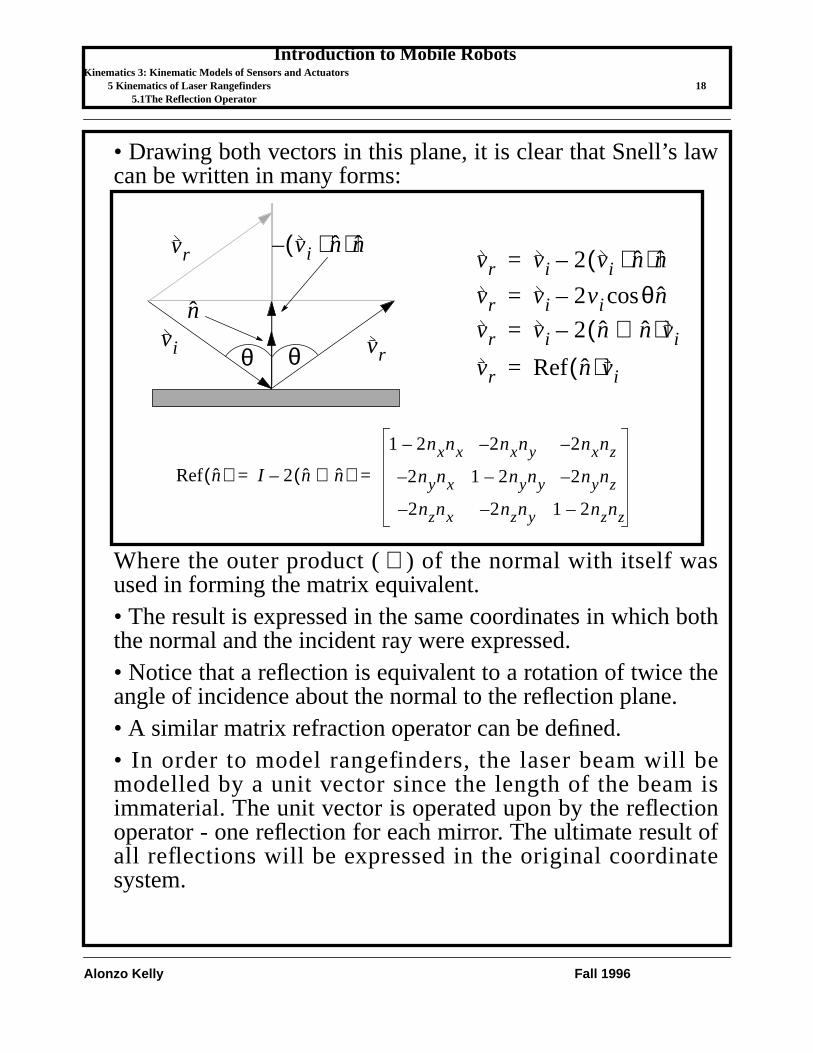
• Drawing both vectors in this plane, it is clear that Snell’s lawcan be written in many forms:
Where the outer product ( ) of the normal with itself wasused in forming the matrix equivalent.• The result is expressed in the same coordinates in which boththe normal and the incident ray were expressed.• Notice that a reflection is equivalent to a rotation of twice theangle of incidence about the normal to the reflection plane.• A similar matrix refraction operator can be defined.• In order to model rangefinders, the laser beam will bemodelled by a unit vector since the length of the beam isimmaterial. The unit vector is operated upon by the reflectionoperator - one reflection for each mirror. The ultimate result ofall reflections will be expressed in the original coordinatesystem.
n̂vi
vr vi n̂⋅( )n̂–vr vi 2 vi n̂⋅( )n̂–=
vrvr vi 2 n̂ n̂⊗( )vi–=
vr vi 2vi θcos n̂–=
θ θ vr Ref n̂( )vi=
Ref n̂( ) I 2 n̂ n̂⊗( )–
1 2nxnx– 2n– xny 2n– xnz
2n– ynx 1 2nyny– 2n– ynz
2n– znx 2n– zny 1 2nznz–
= =
⊗

Introduction to Mobile RobotsKinematics 3: Kinematic Models of Sensors and Actuators
5 Kinematics of Laser Rangefinders 195.2Kinematics of the Azimuth Scanner
Alonzo Kelly Fall 1996
• The results of such an analysis give the orientation of the laserbeam as a function of the actuated mirror angles, but it saysnothing about where the beam is positioned in space. Theprecise position of the beam is not difficult to calculate and isimportant in the sizing of mirrors. From the point of view ofcomputing kinematics, beam position can often be ignored.
5.2 Kinematics of the Azimuth Scanner
• Theazimuth scanneris a generic name for a class of laserrangefinders with equivalent kinematics. In this scanner, thelaser beam undergoes the azimuth rotation/reflection first andthe elevation rotation/reflection second.• Examples are the ERIM and Perceptron. Both scanners are2D scanning laser rangefinders employing a “polygonal”azimuth mirror and a flat “nodding” elevation mirror. Themirrors move as shown below:
noddingmirror
polygonmirror
ys
xs

Introduction to Mobile RobotsKinematics 3: Kinematic Models of Sensors and Actuators
5 Kinematics of Laser Rangefinders 205.2Kinematics of the Azimuth Scanner
Alonzo Kelly Fall 1996
5.2.1Forward Kinematics
• A coordinate system called the “s” system is fixed to thesensor with y pointing out the front of the sensor and x pointingout the right side. The beam enters along the axis. It reflectsoff the polygonal mirror which rotates about the axis. It thenreflects off the nodding mirror, to leave the housing roughlyaligned with the axis.• First, the beam is reflected from the laser diode about thenormal to the polygonal mirror. Computation of the output ofthe polygonal mirror can be done by inspection - noting thatthe beam rotates by twice the angle of the mirror because it is areflection operation. The z-x plane contains both the incidentand normal vectors. The datum position of the mirror shouldcorrespond to a perfectly vertical beam, so the datum for themirror rotation angle is chosen appropriately. Consider an inputbeam along the axis and reflect it about the mirror byinspection:
• Notice that this vector is contained within the xs-zs plane.Now this result must be reflected about the nodding mirror.Notice that, at this point, cannot be simply rotated aroundthe x axis since the axis of rotation which is equivalent to a
xsys
ys
v̂m xs
zs
xs
n̂p
ψ 2⁄
v̂p Ref n̂p( )v̂m=
v̂m 1 0 0T=
v̂p sψ 0 cψT=
ψ
v̂m
v̂p
v̂p

Introduction to Mobile RobotsKinematics 3: Kinematic Models of Sensors and Actuators
5 Kinematics of Laser Rangefinders 215.2Kinematics of the Azimuth Scanner
Alonzo Kelly Fall 1996
reflection is normal to both and . Since is not always inthe ys-zs plane, the xs axis is not always the axis of rotation.
• This result is summarized in the following figure:
• Thus, the kinematics of the azimuth scanner are equivalent toa rotation around the axis followed by a rotation around thenew axis. This is also equivalent to two rotations in theopposite order about fixed axes.
v̂p n̂n v̂p
zs
ys n̂n
v̂n Ref n̂n( )v̂p v̂p 2 v̂p n̂n⋅( )n̂n–= =
v̂p sψ 0 cψT=
v̂nv̂p
n̂n 0 sα2--- c
α2---–
T=
v̂n
sψ0
cψ
2cψcα2---
0
sα2---
cα2---–
+sψ
cψsαc– ψcα
sψ
cψsπ2--- θ–
c– ψcπ2--- θ–
= = =
θ 2⁄
v̂n sψ[ ] cψcθ[ ] cψsθ[ ]–T=
put α2--- π
4--- θ
2---–=
α 2⁄
θ
ψ
xs
ys
zs
Rvs
xs
ys
zs
RsψRcθcψR– sθcψ
= =
xszs

Introduction to Mobile RobotsKinematics 3: Kinematic Models of Sensors and Actuators
5 Kinematics of Laser Rangefinders 225.2Kinematics of the Azimuth Scanner
Alonzo Kelly Fall 1996
5.2.2Forward Imaging Jacobian
• The imaging Jacobian provides the relationship between thedifferential quantities in the sensor frame and the associatedposition change in the image. The Jacobian is:
5.2.3Inverse Kinematics
• The forward transform is easily inverted.
Jis
vi∂∂v
sR∂
∂xs
ψ∂∂xs
θ∂∂xs
R∂∂ys
ψ∂∂ys
θ∂∂ys
R∂∂zs
ψ∂∂zs
θ∂∂zs
sψ Rxψ 0
cθcψ R– cθsψ R– sθcψs– θcψ Rsθsψ R– cθcψ
= = =
vi
R
ψθ
= vs
xs
ys
zs
RsψRcθcψR– sθcψ
= =
R
ψθ
xs2 ys
2 zs2+ +
xs ys2 zs
2+⁄( )atan
z– s ys⁄( )atan
h xs ys zs, ,( )= =

Introduction to Mobile RobotsKinematics 3: Kinematic Models of Sensors and Actuators
5 Kinematics of Laser Rangefinders 235.2Kinematics of the Azimuth Scanner
Alonzo Kelly Fall 1996
5.2.4Inverse Imaging Jacobian
• The imaging Jacobian provides the relationship between thedifferential quantities in the sensor frame and the associatedposition change in the image. The Jacobian is:
5.2.5Analytic Range Image of Flat Terrain
• Given the basic kinematic transform, many analyses can beperformed. The first is to compute an analytic expression for
Jsi
vs∂∂v
i
xs∂∂R
ys∂∂R
zs∂∂R
xs∂∂ψ
ys∂∂ψ
zs∂∂ψ
xs∂∂θ
ys∂∂θ
zs∂∂θ
xs
R-----
ys
R-----
zs
R----
ys2 zs
2+
R2
---------------------ys
R2
------x– s
ys2 zs
2+---------------------
zs
R2
------x– s
ys2 zs
2+---------------------
0zs
ys2 zs
2+-----------------
y– s
ys2 zs
2+-----------------
= = =
vi
R
ψθ
xs2 ys
2 zs2+ +
xs ys2 zs
2+( )⁄( )atan
z– s ys⁄( )atan
= = vs
xs
ys
zs
=

Introduction to Mobile RobotsKinematics 3: Kinematic Models of Sensors and Actuators
5 Kinematics of Laser Rangefinders 245.2Kinematics of the Azimuth Scanner
Alonzo Kelly Fall 1996
the range image of a perfectly flat piece of terrain. Let the
sensor fixed “s” coordinate system be mounted at a heightand tilted forward by a tilt angle of . Then, the transform fromsensor coordinates to global coordinates is:
• If the kinematics are substituted into this, the transform fromthe polar sensor coordinates to global coordinates is obtained:
• Now by setting and solving for , the expression for as a function of the beam angles and for flat terrain is
obtained. This is an analytic expression for the range image offlat terrain under the azimuth transform.
zs
zg
yg(xg,yg,zg)
ys
h
β
R
hβ
xg xs=yg yscβ zssβ+=
zg y– ssβ zscβ h+ +=
xg Rsψ=yg Rcθcψ( )cβ Rsθcψ( )sβ– Rcθβcψ= =
zg Rcθcψ–( )sβ Rsθcψ( )cβ– h+ h Rsθβcψ–= =
zg 0= RR ψ θ
R h cψsθβ( )⁄=

Introduction to Mobile RobotsKinematics 3: Kinematic Models of Sensors and Actuators
5 Kinematics of Laser Rangefinders 255.2Kinematics of the Azimuth Scanner
Alonzo Kelly Fall 1996
• Notice that when R is large . As a check on therange image formula, the resulting range image is shown belowfor , , a horizontal field of view of 140°, avertical field of view of 30°, and an IFOV of 5 mrads. It has490 columns and 105 rows. The edges correspond to contoursof constant range of 20 meters, 40 meters, 60 meters, etc.
• The curvature of the contours of range is intrinsic to thesensor kinematics and is independent of the sensor tilt.Substituting this back into the coordinate transform, thecoordinates where each ray intersects the groundplane are:
• Notice that the y coordinate is independent of and hence,lines of constant elevation in the image arestraight lines alongthe y-axis on flat terrain.• From the previous result, it can be verified by substitution andsome algebra that:
• Thus lines of constant azimuth arehyperbolas on thegroundplane.
sθβ h R⁄=
h 2.5= β 16.5°=
xg htψ sθβ⁄=yg h tθβ⁄=
zg 0=
ψ
xg
tψ------
2yg
2– h2=

Introduction to Mobile RobotsKinematics 3: Kinematic Models of Sensors and Actuators
5 Kinematics of Laser Rangefinders 265.2Kinematics of the Azimuth Scanner
Alonzo Kelly Fall 1996
5.2.6Resolution
• The Jacobian of the groundplane transform has many uses.Most important of all, it provides a measure of sensorresolution on the ground plane. Differentiating the previousresult:
• The determinant of the Jacobian relates differential areas:
• Notice that when R is large and , the Jacobian norm canbe approximated by:
• Thus, the pixel density on the ground is proportional to thecube of the range.
dxg
dyg
h ψsec( )2
sθβ----------------------- h– tψcθβ
sθβ( )2----------------------
0h
sθβ( )2-----------------
dψdθ
×=
dxgdygh ψsec( )2
sθβ( )3----------------------- dψdθ=
ψ 0=
h ψsec( )2
sθβ( )3----------------------- h
2 hR---
3⁄≈ R
2 hR---
⁄=
Introduction to Mobile RobotsKinematics 3: Kinematic Models of Sensors and Actuators
5 Kinematics of Laser Rangefinders 275.3Simple Scanner Kinematics
Alonzo Kelly Fall 1996
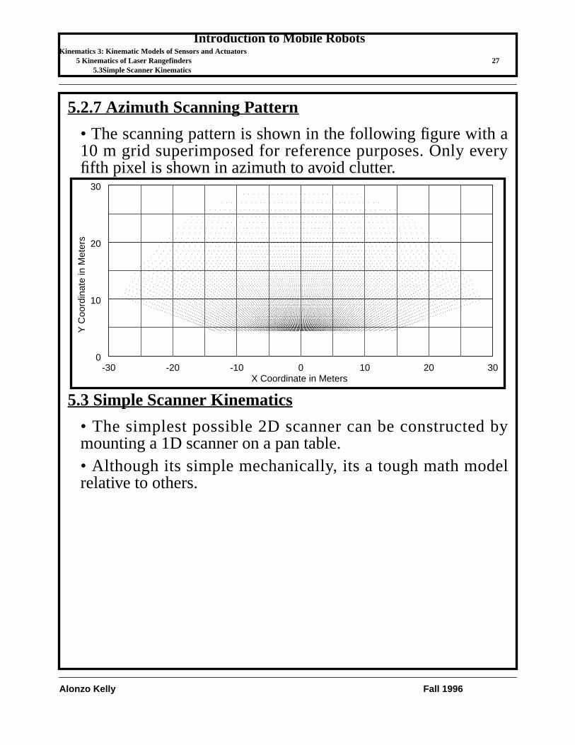
5.2.7Azimuth Scanning Pattern
• The scanning pattern is shown in the following figure with a10 m grid superimposed for reference purposes. Only everyfifth pixel is shown in azimuth to avoid clutter.
5.3 Simple Scanner Kinematics
• The simplest possible 2D scanner can be constructed bymounting a 1D scanner on a pan table.• Although its simple mechanically, its a tough math modelrelative to others.
-30 -20 -10 0 10 20 300
10
20
30
X Coordinate in Meters
Y C
oord
inat
e in
Met
ers

Introduction to Mobile RobotsKinematics 3: Kinematic Models of Sensors and Actuators
5 Kinematics of Laser Rangefinders 285.3Simple Scanner Kinematics
Alonzo Kelly Fall 1996
• We will model this one with our fundamental operators andrules for forward kinematic modelling.
5.3.1Forward Kinematics
• The homogeneous coordinates of a range pixel in the mirror(m) frame are:
• To convert the coordinates of this pixel to the intermediate (i)frame, we must generate the relevant transform as follows. Theoperations which bring frame i into coincidence with frame mare:
• Translate along a distance .• Rotate around an angle .
• Hence, the matrix which converts coordinates of a pointfrom frame m to frame i is:
R
xm
ym
zm
xi yi
zi
xs ys
zs
xr yr
zr
le
lrla
ψ azimuth,
θ elevation,
vm 0 0 R– 1T
=
yi ym= leyi ym= θ
Tmi

Introduction to Mobile RobotsKinematics 3: Kinematic Models of Sensors and Actuators
5 Kinematics of Laser Rangefinders 295.3Simple Scanner Kinematics
Alonzo Kelly Fall 1996
• Therefore, the coordinates of a range pixel in the i frame are:
• To convert the coordinates of this pixel to the sensor (s)frame, we must generate the relevant transform as follows. Theoperations which bring frame s into coincidence with frame iare:
• Translate along a distance .• Rotate around an angle .
• Hence, the matrix which converts coordinates of a pointfrom frame i to frame s is:
Tmi
1 0 0 0
0 1 0 le0 0 1 0
0 0 0 1
cθ 0 sθ 0
0 1 0 0
sθ– 0 cθ 0
0 0 0 1
=Tm
iTrans 0 le 0, ,( )Roty θ( )=
Tmi
cθ 0 sθ 0
0 1 0 lesθ– 0 cθ 0
0 0 0 1
= Tim
cθ 0 sθ– 0
0 1 0 le–
sθ 0 cθ 0
0 0 0 1
=
vi Tmi
vm=
x
y
z
w i
cθ 0 sθ 0
0 1 0 lesθ– 0 cθ 0
0 0 0 1
0
0
R–
1
=
vi Rsθ– le, Rcθ–, 1,T
=
zs zi= lazs zi= ψTi
s

Introduction to Mobile RobotsKinematics 3: Kinematic Models of Sensors and Actuators
5 Kinematics of Laser Rangefinders 305.3Simple Scanner Kinematics
Alonzo Kelly Fall 1996
• Therefore, the coordinates of a range pixel in the s frame are:
• The last expression is the complete sensor forward kinematicssolution which converts coordinates from range, azimuth,elevation to a cartesian (x,y,z) position with respect to thesensor frame.
Tis
1 0 0 0
0 1 0 0
0 0 1 la0 0 0 1
cψ sψ– 0 0
sψ cψ 0 0
0 0 1 0
0 0 0 1
=
Tis
Trans 0 0 l, a,( )Rotz ψ( )=
Tis
cψ sψ– 0 0
sψ cψ 0 0
0 0 1 la0 0 0 1
= Tsi
cψ sψ 0 0
sψ– cψ 0 0
0 0 1 la–
0 0 0 1
=
vs Tisvi=
x
y
z
w s
cψ sψ– 0 0
sψ cψ 0 0
0 0 1 la0 0 0 1
Rsθ–
leRcθ–
1
=
vs
Rcψsθ– lesψ–
Rsψsθ– lecψ+
Rcθ– la+
1
=

Introduction to Mobile RobotsKinematics 3: Kinematic Models of Sensors and Actuators
5 Kinematics of Laser Rangefinders 315.3Simple Scanner Kinematics
Alonzo Kelly Fall 1996
5.3.2Inverse Kinematics
• The goal of the inverse kinematics is to compute the range,and the azimuth and elevation angles which correspond to agiven cartesian (x,y,z) position expressed with respect to thesensor frame.• The forward kinematic relationship can be rewritten asfollows:
• The inverse kinematic solution can be obtained by assumingthat is known and solving for the range, azimuth, andelevation of the point. Premultiplying the above by :
vi Tmi
vm=
vs Tisvi=
vs Tis
Tmi
vm =∴
vsTs
i
Tsivs Tm
ivm vi=( )=
cψ sψ 0 0
sψ– cψ 0 0
0 0 1 la–
0 0 0 1
x
y
z
w s
cθ 0 sθ 0
0 1 0 lesθ– 0 cθ 0
0 0 0 1
0
0
R–
1
=
Introduction to Mobile RobotsKinematics 3: Kinematic Models of Sensors and Actuators
5 Kinematics of Laser Rangefinders 325.3Simple Scanner Kinematics
Alonzo Kelly Fall 1996
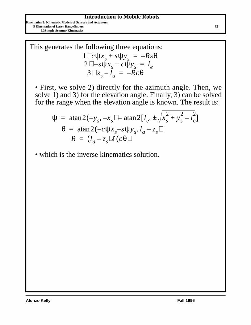
This generates the following three equations:
• First, we solve 2) directly for the azimuth angle. Then, wesolve 1) and 3) for the elevation angle. Finally, 3) can be solvedfor the range when the elevation angle is known. The result is:
• which is the inverse kinematics solution.
1) cψxs sψys+ Rsθ–=
3) zs la– Rcθ–=2) sψxs– cψys+ le=
ψ 2 ys xs–,–( ) 2 le xs2
ys2
le2
–+±,[ ]atan–atan=
θ 2 cψxs sψys la zs–,––( )atan=R la zs–( ) cθ( )⁄=

Introduction to Mobile RobotsKinematics 3: Kinematic Models of Sensors and Actuators
6 Summary 335.3Simple Scanner Kinematics
Alonzo Kelly Fall 1996
6 Summary• The RPY matrix is yet another compound orthogonaloperator matrix. Unlike the DH matrix, it has 6 dof so it iscompletely general.• Angular velocity is related in a complicated manner to therates of roll, pitch, and yaw angles.• Video cameras are modelled by a perspetive projection.• Laser rangefinder models are nonlinear and cannot berepresented by a constant homogeneous transform like acamera can.• However, our mechanism modelling rules apply perfectly andone can also use a reflection operator to model them.

Introduction to Mobile RobotsKinematics 3: Kinematic Models of Sensors and Actuators
6 Summary 345.3Simple Scanner Kinematics
Alonzo Kelly Fall 1996