kinematic simulation of staubli tx40 robot-icm
TRANSCRIPT

8/16/2019 Kinematic Simulation of Staubli TX40 Robot-ICM
http://slidepdf.com/reader/full/kinematic-simulation-of-staubli-tx40-robot-icm 1/6
reen te ntetnl nerene n etrnrl , , tnl Treynamic odelin and Kinematic imulation of
tubli© TX4 Robot Usin MATLAB/ADAMSCo-simulation
Farzad Cheraghpou, IEE Membel1, Masoud Vaezi#2, Resam Eddin Shoori Jazeh#3, S. Ai A. Moosavian#4# Islamic Azad Universi, Pardis Branch, Department ofMechanical Engineering, Iran
# N Toosi Universi of Technolo, Department ofMechanical Engineering, Iran# N Toosi Universi of Technolo, Department of Electrical Engineering, Iran
# N Toosi Universi of Technolo, Department ofMechanical Engineering, Iran
samavai@padisiauacimasoudvai@maicomhsamshooi@maicommoosavia@uaci
This paper presents dynamic modeling and simulation
of the industrial robot, Stubli TX40, and proposes a precisesimulator to develop approaches for experimental simulation innematics, dynamics and control analysis. The robot model hasbeen developed as accurate as the real one by implementingdynamic model of robot in ADMS, dynamic modeling software,and also linking with TL for motion studies. Finally thesimulator is veried by tracking a predened pose withminimum error.
KewordsRobot, Dynamic Modeling, Simulation, Inverse andForward Kinematics, Genetic Algorithm
I. NTRODUCTION
In recent decades, robot aipuators are widey used inndusia appications. Of te most imporant ones, wedingad panting robots n car pats [], eeconic boadassemby, reparng nucea instaations [], and etc ca bementioned.
Besides, academic and research Labs try to deveop newmethods and agorithms so as to reease te resuts forndusia uses aer vaidation. The researches are appied todierent areas such as motion panning, manipuation
paning [3,,], asp paning [6,7,], d conoagorims ike position contro [9], force contro [0],Impedance contro [,], and etc. Rea robots arenaccessibe due to high prices terefore creating precise
simuated modes are etensivey demanded by research Labs.Prio o s, simuaton and anayss of PUA 60 as one
of e most renowned ndusia robots have been perfomed[3]. With the advent of new modes of robot manipuators bymaufactrers, sti there is a need for eact simuated modes.This paper introduces simuated modes of 6-DOF tubi
©
TX0 rbot. A procedes presented n is paper e in way tat reader c mode specic robot n soware envronments.The ma advantage of this paper is to use muti-soweenvronments interactivey. Aer a 3D modeing of robotmipuator in CATIA soware, as it wi be mentioned
97--4-9-0//$00 ©0 EEE
competey, the mode is epored to ADA dynamicmodeing soware. This soware is capabe of simuatingkinematics and knetics behavior of y mechanica system.As resut dynaic behavior of systems wi comparison to the rea modes can be simuated with an acceptabe eor.
For obtag an eact modeing, neria and geomeic parameters are accatey meased and recorded n thesoware database. Aso for simuating cono agorims, cosimuation between ADA and MATLAB is performed.
II. MLGIn modeng using CATIA, CAD soware, rbot mode is
divided into seven pats. Each individua par is designed n
"Par Design separatey. The sketches are obtained from themanufacturer company []. Aerwards tese parts are reproduced n "Assemby environment and assembed withconsant comands. The process of deing consaintsstars wit ing the base par usng "Fi comand and endsup with reproducng the other ps and appyng "Contactand "Coincidence to each coupe of them. To vaidate temotion of 6-DOF robot, "manipuation command is used.The assembed mode of robot d he rea one are shown nFige .
B
Fig. 1 A. created mel CATIA B. e real Stub©
TX40 robot
386
8/16/2019 Kinematic Simulation of Staubli TX40 Robot-ICM
http://slidepdf.com/reader/full/kinematic-simulation-of-staubli-tx40-robot-icm 2/6
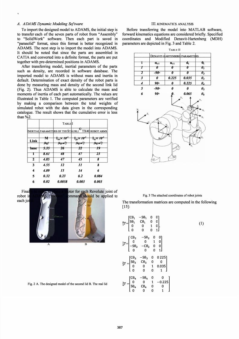
A. ADAMS Dynamic Modeling Sofare
To import te designed mode to D, e initia step is to ansfer each of the seven parts of robot from "Assemby to "oidWork soware. Then each part is saved in"paasoid format, since this format is better recognized nDAM. The net step is to import te mode nto DM.It shoud be noted tat since the parts are assembed n
CATIA ad convered nto a dete format, the parts are put together wit pre-determined positions in AD.Aer ansfeng mode, nertia parameters of the parts
such as density, are recorded n soware database. Theimported mode to DM is witout mass and nertia ndefaut. Determnation of eact density of te obot parts isdone by measring mass and density of e second k id(Fig. ). Thus DM is abe to cacuate te mass andmoments of inertia of each par automaticay. The vaues areiusated in Tabe . The computed parameters are veried by making a comparison between e tota weights ofsimuated robot with the data given in the coespondingcataogue. The resut shows at the cumuative eor is ess
t %.BLE I
ERTL PETER OF THE STABU©
X40ROBOT
M If ] X If ] X If ] Link [ kg k g k g base 5.35 26 22 19 8.61 48 47 23 4.85 4 7 45 8 4.55 12 11 8
4 4.09 15 14 6
0.320 . 23 0 . 2
0.084 0.02 0.0058 0.003 0.003Finay n order to pace a motor for each Revoute jont of
robot in DM, "motion command shoud be appied toeach jont.
Fig. 2 A. The desied odel of the second lid B. e el lid
III. TI CS YSIS
Before sfeng e mode nto MATLB soware,forward knematics equations are considered briey. peciedcoordnates and Modied Denavit-Hartenberg (MDH) paameters are depicted in Fig. 3 ad Tabe .
i
1 23456
.
z
�
BLE II
DEN VT -HRTEBERG PETER
-1 a _ d 90 0 0 -90 0 0 0 0.225 0.035 90 0 0.225 -90 0 0 90 0 0.065
z,
Fig. 3 The ttched coordintes of robot jonts
The sformation maices are computed n te foowing[15]: C'= �
0[ C,- C = 003 _0
C
000000
0
0
0!l
0 ()
10 0 !l1000 l01 0.030 10
S
l100
387

8/16/2019 Kinematic Simulation of Staubli TX40 Robot-ICM
http://slidepdf.com/reader/full/kinematic-simulation-of-staubli-tx40-robot-icm 3/6
4 0 CO,s - �Os
5
0[CO'
6- S
g6
SOs0COs0
S06
0C0
60
0 �]000 -Of65]
00 which C , are representative for Cos() and in(), respectivey.
The foowng reation species the end effector positionand orientation wi respect to te base.
2T is a x mai whose eements e shown n Appendi.The position of jonts rough e process of transfeng
into ADA is considered as zero state n defaut. Consequenty, when assembing mode n CATIA, zero state
of te jonts shoud be e same as zero state of speciedcoordnates. Fig. shows zero state of tubi obot jonts. Toadapt te direction of jont motion wit te rea robot, te positive direction of rotation shoud be compatibe wit right handed direction of Z ais.
Fig. 4 Zero stte of joint gles in S
A. Inverse Kinematics
The nverse kinematics probem consists of e
determnation of jont viabes correspondng to a given endeector osition and orientation. The soution to tis probemis of ndamenta importance in order to trsform te motionspecications, assigned to te end eector n operationaspace, into te coespondng joint space motions at aoweecution of desired motion.
Inverse knematics of 6-DOF tubi manipuator consistsof estabishing cosed anaytica equations of the jont spaceusing agebraic and trigonomeic meods and the na resuts are specied in equations 3.
81=Atan2(P y ,p x )-Atan2(d3,± p
P
d
(3)
82 =Atan [(-a3-a2C3)P z+(Clpx +S1P y)(a2S3-d4)(a2C3- d4)pz+(a3+a2C3)(CIP x +S1P y)]-
83=Atan(a3,d4)-
Atn2(a3c3 -d4S
3 ±.a
�
+ d� + (a3c 3 - d4s3)2
84=Atan(-T13s1+T23Cl , -T13CIC23-T23S1C23+T33S23)
85= Atan (S,C)
86=Atan(s6,c 6)
Due to e nonnearity of equations, ter cosed soutionmight be dicut to attan, so the Genetic Agoritm as anerica method has been considered for cacuatng ,[6]MATL soware aims at achieving jont space variabes fora given end effector position and orientation (Eq) based onGA. The comparison between GA resuts d anayticasoution is made in Tabe 3. It shoud be stated at anguarimits are assigned to each motor tat ead to ique soution[7]. Fig. iusates te eor between numerica soution of
te inverse kinematics and anaytica soution tat is about
3.06e
ll
=-0.6
=. rad =-0.
=0.00 rad
LE III
=0.
\ =. rad
COMRON OF NERCL OLTON WT NLTCL ONE
Jointangles
7
h
4"
3
2
Closed Geneticequations Algorithm
[rad] [rad]0.7165 0.7165- 2.0048 - 2.00520.2143 0.21450 01.7912 1.7908-0.7165 -0.7165
B 3.060ge·')11 M 471e-8
Errorpercentage
[%]0.0000.0190.0930.0000.0220.000
f 1
()
0
0
0 � 00-
�
-�
0
0
I PQ Gr
Fig. 5 Nuericl solution eor usng Genetic lgorit
As seen in Tabe 3, consequences of numerica soution arehighy acceptabe and reiabe.
388

8/16/2019 Kinematic Simulation of Staubli TX40 Robot-ICM
http://slidepdf.com/reader/full/kinematic-simulation-of-staubli-tx40-robot-icm 4/6
B. MATLB and ADAMS Co-simulation:
MATLAB is a power too for appying conocomands to the robot so for havng ecient simuator package, te co-simuation between ADAM MATLA isnoticeabe. order to eecute a co-smuation betweenADAM and MATLAB, deition of an acceptabe foatfor te nputs and ouuts of each progra is required. The
objective of co-simuation is to make a connection so tat anychange in one of the programs affects the other one [].To provide a simuation that enabes ADMA to recognize
the eported ouut om MATLAB, there is a need foractivating "contro pug-in in "Pug-in Manager of AMand dening e robot as a pant Aer activation, a newwindow appears for the determnation of pant and its inputsand outputs. Aerwds, ADAM saves dynamic mode of robot motion as a compe of seven matrices tat is capabe ofsending to MATLAB. The rst fo are A,B,C,D maices ofstate-space representation. The h and sit maices areassociated wit predeed nputs and ouuts. And te astone incudes nformation about state varabes of te pant
[9,0]. Trajectory panning of each robot joint ((t)), asADAM inputs, is stated as a ve-degree poynomias forsoving forward kinematics of robot, [].
This nction is suitabe for each joint te view pont ofdynamic considerations, [].
()
The coecients of this nction regardng to nitia anda position, veocity, acceeration vaues of each joint areassigned based on equations in []. ADAM ouuts arecomponents of end effector position (,y,z) with respect to theame atached to te base.
To ca the generated pt in MATLAB, the pt nameshoud be entered in e "comand window so that the inputand ouut information wi appear. By eecuting "Adams_syscommand, e bocks containing nformaton about dnamicmode of robot in IMINK envronment, are aded.(Fig. 6)
S-Funtin
-D
Stat· Spa e
damsb
Fig. 6 odel plnt d stte spce blocks
By having "Adams-sub bock n IMLINK environment, the robot mode is suitabe for cono and motion simuationas a deed system in MATL.
Regdng te forard knematics of robot, te a sformation matri d trajectory panning bock are
generated in "Embedded MATLAB Funcon. Ouuts of tis bock represent e pant inputs of robot n ADAM. Bysting the simuation n IMIK, the signas of ctioncoecients for (t) wi enter the pt and ADAMsimuteousy which contnues to a deite a state.Generated ajectory ctions for each motor yieds the endeffector to ack te desired position d orientation. Fig. 7demonsates te bock diagram of forward kinematics.
f
�
0
8
G
8c
G
�
c
8
;
0
�
-
.
.
·:
·
-
·
1
�
�
'
-
·
=.
Fig. 7 block digr of forwrd kintics in SULK
In tis simuation nitia vaues of position, veocity dacceeration and aso a veocity and acceeration of eachjont are presumed to be zero. The a position of each jont,, in period of seconds is assumed as equation 6.
8f= [0.75 - 0.5 0 .79 -0.75] (6)
Wit these 6 vaues of initia and a position, veocity,acceeration a 6 coecients of te equation can be
determined so at trajectory ction of te jonts aregenerated. The a nctions are as equation 7.
1(t) = 0.5t 3-O.7t 4+O.07t2(t) = -0.77t 3+0.7t 4-0.09t3(t) = 0.079t 3_0.09t 4+0.005t4(t) = 0(t) = 0.t 3_0.t 4+0.0t6(t) = -0.5t 3+O.7t 4-O.07t
(7)
Based on the anatica vieoint d forward kinematicssoution, each joint approaching its given a position, , eend effector must ack te position and orientation according
to equation Note tat ,
are ro, pitch, yaw ages
respectivey
-0.6 mOOO rad
0 m000 rad
p 0. m'000 rad
By e end of e simuation, te end effector position nwork space is depicted n scope of MA TLA/IMLINK Fig. By comparng te resuts wit e forward kinematicssoution, it c be infeed that the simuation satises odesred accacy.
389

8/16/2019 Kinematic Simulation of Staubli TX40 Robot-ICM
http://slidepdf.com/reader/full/kinematic-simulation-of-staubli-tx40-robot-icm 5/6
� r 1 , .... 1 �
co�
• I , D :.... ..�... ....!.. . .....� <
r
�
�
]01 '_ I _ • l . _ .
o j o ¥
�OA
' � OJ •
=� ' : ...
\. . . . · t·
.
)
.�
J Il
L -
-
:
:'-
- ()Fig. e d eector position showing n scope
IV. ONCLUSIONS
In is paper modeng d simuation of 6-DOF tubi robot have been performed using CATIA, ADA,MAAB rograms he Denavit-arenerg and ineia parameters and aso kinematic anaysis of robot wereepoited. hen te procedure of estabishing a co-simuation between ADAM and MALAB has been ceay epressedad the owchar n Fig. 9 shows the whoe process.
Consequences of tis simuation cari te coect guidanceof robot n e sowe modeng. With the hep of createdmode, design d simuation of cosed oop cono systemsand appyng optimized design parameters are simpyeecutabe.
[]
[ 2]
[3]
[4]
[5]
[6]
[7]
[]
[ 9]
Analysis fr fa knematis
Dtmat f ut, uut alat DM®
Crating M-File f nd fft tranfatin aie
Fig. 9 e owchar sowing e procedre of cosilaon
EFERENCES
K. T. Pk Y. J. Shn and C. H. Park Y. S. Mo D. C. JeongY. S.Shn"Robot Application for Assembly Process of Engne ParInteational Conference on Control Atoation d Systes nC K 1 200 Ray M. Singh "evelopent of a Force Reectng Telerobot for
Reote Hdlng in Ncle Installations 1st teationalConference on Applied Robotics for e Power dstry Delta CentreVille Montral Cada p.p 16 2010F. Cherapour. S.A.A Moosavi and A. Nvi "Mltiple Aspectasp perfoance ndex for coopative object iplation tasksEE/AS t. Conf. on Advanced telligt Mechatronics pp 36391 2009M. Eslay S.A.A Moosavian "naics and Cooperative objectManiplation Control of Sspended Mobile Miplators J tellRobot Syst Springer SciencBsness Media B.V pp. 119 2010K. Harada Kaneko F. Kanehiro "Fast asp Plg forH/s Sstes Based on Convex Model EE teationalConference oRobotics d Atomation pp. 17 200F. Cherapor. S.A.A Moosavian and A. Nahvi "Robotic grasp planng by ltiple aspects grasp index for object aniplation tasks8 Iri Conf. on Electrical Engneering (ICEE) pp 635640 2010
A. Agovic N. Papakolopolos "asp Plnng by Alient ofParwise Shape Descriptorss EERSJ teational Confeence onIntelligt Robots d Sstes pp. 1 2009M. Strdberg B. Wahlberg "A Method for asp Evalation Basedon isturbance Force Rejection EE trstis on robotics pp. 1 9 2006M. rii S.A.A. Moosavian "Modied Trnspose EffectiveJacobi Law for Conol of Underactated MiplatorsKoniklijke Brill N Leiden and The Robocs Society of Jap pp.605626 2009
[10] G. Zeng A. Hei "n overview of robot force control RoboticaCabridge University Pess vole 15 pp. 473 42 1997
[11] S.A.A. Moosavi and E. Papadopolos "Cooperative ObjectMiplation with Contct pact Usng Mltiple pedance Conol
39

8/16/2019 Kinematic Simulation of Staubli TX40 Robot-ICM
http://slidepdf.com/reader/full/kinematic-simulation-of-staubli-tx40-robot-icm 6/6
[12
[13 )
[14
[15[16
[17
[1
[1 9 )
[20
[ 21
[ 22
Inteational Joal of Conol Autoation and Systes pp 314327. 2010S. Dehghani H.D. Taghrad M Darany "Selftuning DaicIpedance Control for Hu Ar Motion Bioedical Engineerg(ICBME) 17 Iri Conference pp. 16 2010B. strong O. hatib And J. Burdick "The Explicit DaicModel d erial Paraeters of the PUMA 560 " Robotics AndAutoation EE teational Conf pp 51051 196
©Stub i TX product leaet AT ht://www.staubli.co.
J.J.Craig
RbAddisonWesley pp 16 2005P. shi y. cuiDynamic pa plng for obile robot based on
genetic algori n own envronent conol and decisionconfence (CCDC) china p.p 4325 4329 2010
G. pengfei w. xuezhi h. yngshi "The ehced genetic algorithsfor the optiition desi Bioedical Engneering d foratics(BME 2010 3 teational Conference on pp 29902994 2010Z. Yi X. Mn Q. Jnyi Z. Hu "Research on cosiulation usng ADAMS and MATLAB for autoobile active suspensionsst Coputer Application d Syste Modeling (ICCASM)Inteational Confce p.p V14366 V 4370 2010.Z. A L. Rodhe "ADAMS/SMULK interface for DnaicModelng d Conol of Closed Loop Mechiss Proceedngs of e 7 WSEAS Inteational Conference on autoatic control odelng d siulation Prague Czech Rublicpp. 3533562006Z.Z. Nang M.P. AMaun "teated ADAMS+MATLAB
enviroent for desi of autonoous sngle wheel robot Industrial Electronics.CON 35th nual Conferece of EE p.p 2253225 2009T. Fraichard hone Alpes oble "Dnaic trajectory
plning wi daic consaints: A 'statetie space approachIntelligent Robots d Systes 93 OS 93. Pceedngs of e 1993EERSJ teational Cferce p.p 1393 1400 vo.2 2002. Y. Guan K. Yokoi O. Stasse A. Khedd " robotic tjectory plang usng polynoial nteolations Robotics d Bioietics(ROBIO). EE teational Coference p.p 111 116 2006.
PPEND
81 = t84 = t
82 = t85 = t
CI = Cos81 Sl =n 81
'11 =- sin(t6)*(cos(t)*sn(t)-sin(t)*(cos(t)*sin(t)*sn(t3)-cos(t)*cos(t)*cos(t3)))cos(t6)*(cos(t )*(sn(t)*sn(t)+cos(t)*(cos(t)*sin(t)*sn(t3)-cos(t)*cos(t)*cos(t3))) +
sin(t )*(cos(t )*cos(t)*sn(t3)+ cos(t)*cos(t3)*sin(t)))-();
'12=Sn(t6)*(cos(t )*(sn(t)*sn(t)+cos(t)*(cos(t)*sin(t)*sn(t3)-cos(t)*cos(t)*cos(t3))) +sin(t )*(cos(t)*cos(t)*sn(t3)+ cos(t)*cos(t3)*sn(t))) -cos(t6)*(cos(t)*sin(t)- sn(t)*(cos(t )*sin(t)*sin(t3)cos(t)*cos( )*cos(t3)));
'1=cos(t )*(cos(t)*cos(t)*sin(t3)+cos(t )*cos(t3)*sin(t))-sn(t )*(sn(t)*sin(t)+cos(t)*(cos(t)*sin(t)*sn(t3)- cos(t)*cos(t)*cos(t3)));
P x =(9*cos(t )*cos( ))/0-(7*sn(t))/00-(3*sn(t )*(sin(t)*sn(t)+ cos( t)*(cos(t)*sn(t)*sn(t3)cos(t )*cos( )*cos(t3))))/00+(3*cos(t )*(cos(t )*cos( )*sn(t3)+cos(t)*cos(t3)*sn(t)))/00+ (9*cos(t)*cos( )*sn(t3))/0+(9*cos(t)*cos(t 3)*sin(t))/0+(0.6);
'21 =sn(t6)*(cos(t)*cos(t)+sin( t)*(sin( t)*sn( t)*sn( t3)-cos( t)* cos( t3)*sin( t )))+cos(t6)*(cos(t )*(cos(t )*sn(t)-cos( t)*(sn( t )*sn( t)*sn( t3)-cos( t)*cos( t 3 )*sin( t)))sin(t )*(cos(t)*sn(t)*sin(t3)+cos(t3)*sn(t)*sn(t)));
'22 =cos(t6)*(cos(t)*cos(t)+sin( t)*(sin( t)*sn( t)*sn( t3)-cos( t)* cos( t3)*sin( t )))sn(t6)*(cos(t )*(cos(t )*sn(t)-cos(t)*(sn(t)*sn( )*sn(t3)-cos(t)*cos(t3)*sin(t))) -sn(t )*(cos(t)*sn(t)*sin(t3)+cos(t3)*sn(t)*sin(t)))-();
'2 =sin(t )*(cos(t )*sin(t)- cos(t)*(sin(t)*sn(t)*sn(t3)cos(
)*cos(t3)*sn(t)))+cos(t )*(cos(t)*sin(t)*sn(t3)+cos(t3 )*sn(t)*sn(t));
P y =(7*cos(t))/00 + (9*cos( )*sn(t))/0+(3*sn(t )*(cos(t)*s (t)- cos(t)*(sin(t )*sn( )*sin( t3)cos( )*cos(t3)*sn(t ))))/00+(3*cos(t )*(cos(t)*sn(t)*sn(t3)+cos(t3)*sin(t)*sin(t)))/00+(9*cos( )*sn(t)*sn(t3))/0 +(9*cos(t3)*s (t )*sin(t))/0+(0.);
'1 =sin(t)*sn(t6)*(cos(t)*sin(t3)+cos(t3)*sn(t))cos(t6)*(sn(t )*(cos(t)*cos(t3)-sn(t)*sin(t3)) +cos(t 4)*cos(t5)*(cos(t 2)*si (t3)+cos(t 3)*sin( )));
'2 =s (t6)*(sn(t )*(cos( )*cos(t3)-sn( )*sin(t3))+cos(t)*cos(t)*(cos(t)*sn(t3)+cos(t3)*sn( )))+cos( t6)*sin( t)*(cos( )*sn( t3)+cos( t3)*sn( ));
' =cos(t )*(cos( )*cos(t3)-sn(t)*sn(t3))cos(t)*sin(t)*(cos( )*sn(t3)+cos(t3)*sn() )-();
P z =(9*cos( )*cos(t3))/0-(9*sn(t))/0-(9*sn(t)*sin(t3))/0+(3*cos(t )*(cos( )*cos(t3)sin(t)*sin(t3)))/00-(3*cos(t)*sn(t )*(cos( )*sn(t3)+cos(t3)*sin(t)))/00-(0.);
391