kick-down or straight-acting jacks with or without … or straight-acting jacks r ... begin...
TRANSCRIPT

SERVICE MANUAL
ML13514/MI91.001406MAY04
Touch Panel BI-AXIS ControlCentral Grounding
FEATURING:
HWH CORPORATION(On I-80, Exit 267 South)
2096 Moscow Road | Moscow, Iowa 52760Ph: 800/321-3494 (or) 563/724-3396 | Fax: 563/724-3408
www.hwh.com
310 SERIES LEVELING SYSTEMHWH TOUCH PANEL-CONTROLLED
WCORPORATIONH H R
R
Kick-Down or Straight-Acting Jacks
R
With or Without Air Dump
SECURELY BEFORE REMOVING TIRES OR CRAWLING UNDER VEHICLE.
UNDERSTAND OPERATOR’S MANUAL BEFORE USING. BLOCK FRAME AND TIRESCAUTION!
HWH HYDRAULIC LEVELING
LEVEL
OFF
STORE
HYD
PARK/BRAKE
DUMP
NOT IN

SECTION 1
MI91.101518JUN01
SECTION2
REPAIR STEPS
SECTION3
DIAGRAMS
SECTION
1
TROUBLE
SHOOTING
STEPS
3 PART FOLDER
HOW TO USE MANUAL
PROCEED WITH TROUBLE SHOOTING GUIDE
This manual is written in three sections. Section 1 is the Trouble Shooting Steps. Section 2 is the Repair Steps. Section 3 isthe Diagrams. Begin diagnosis of the system with Section 1, the Trouble Shooting Steps. This will give the correct operationand function of the system. When a malfunction is encountered, the Trouble Shooting Steps will direct you to the proper RepairSteps in Section 2, the Repair Steps. The Repair Steps are broken into 3 columns, Problem, Solution, and Diagram. In theproper part under Problems, find the symptom you have encountered. The testing and repair for that problem is in the Solu-tion (center) column. Diagrams for a particular Problem and Solution are in the Diagram (right hand) column. This column willdirect you to the proper diagram in Section 3, Diagrams, for a more detailed view.
Before beginning your repair, it is IMPORTANT to read the CAUTIONS and NOTES AND CHECKS in the first section, TROUBLESHOOTING STEPS. In many cases this will save time and mistakes when trouble shooting a system.
This Repair Manual is offered as a guide only. It is impossible to anticipate every problem or combination of problems. Thismanual is written in sequential order of the proper operation of the system. The Trouble Shooting Steps must be followed inorder to give correct diagnosis of the problem(s). For any problems encountered that are not addressed in this manual, contactHWH Corporation for assistance.
NOTE: Diagrams in this manual are of typical systems. There may be plumbing or harness differences. In most casesthis should not effect trouble shooting procedures.

TROUBLE SHOOTING
MI91.105521APR11
NOTES AND CHECKSRead and check before proceeding with Trouble Shooting Steps.
NOTE: HWH CORPORATION ASSUMES NO LIABILITYFOR DAMAGES OR INJURIES RESULTING FROM THEINSTALLATION OR REPAIR OF THIS PRODUCT.
1. If the jacks cannot be retracted, see TROUBLE SHOOTING Step8 for temporary measures. Make sure the manual retractvalves are closed before trouble shooting.
2. The Trouble Shooting Guide must be followed in order. Prob-lems checked for in one step are assumed correct and notchecked again in following steps.
retracted position.
6. Do not replace the control box unless the Repair Steps sayto replace it. Otherwise the malfunctions may damage thenew control box.
5. Proper grounding of all components is critical. See the electricalcircuit for specific grounds required. Faulty grounds, especiallyfor the control box, solenoid manifold or the pump assembly,may cause control box component damage and /or improperor erratic operation.
This manual is intended for use by experienced mechanicswith knowledge of hydraulic and automotive electricalsystems. People with little or no experience with HWHleveling systems should contact HWH technical service(800-321-3494) before beginning. Special attention shouldbe given to all cautions, wiring, and hydraulic diagrams.
Special note: When installing a new control box, makesure the box is properly grounded before applying powerto the system.
Suggested tools for trouble shooting the HWH leveling systems:JUMPER WIRES(UP TO 10 GAUGE)PRESSURE GAGE(3500 PSI MIN.)MULTI-METER12 VOLT TEST LIGHT
PROCEED WITH THE TROUBLESHOOTING STEPS ON THE
FOLLOWING PAGE
3. Check that the oil reservoir is full with the jacks in the fully
existing hose end, tighten the hose end to snug plus 1/4tighten the hose end 1/3 turn (2 FLATS). If tightening anmake the hose end snug (finger tight) on the fitting, thenTightening of hose ends: If tightening a new hose end,
turn (1 FLAT).
will not supply enough power for the system to operate properly.with no weak cells. An alternator, converter or battery chargergood voltage under load. Batteries must be in good conditionunder no load should read 12.6 volts. Batteries must maintainthe coach batteries to supply power to the pump. Batteriespower for the control box and hydraulic pump. DO NOT useand the other(s) for the coach. The engine battery supplies4. Most coaches have more than one battery; one for the engine
REAR WHEELS, THE VEHICLE MAY ROLL FORWARD OR BACKWARD OFF THE JACKS.DO NOT OVER EXTEND THE REAR JACKS. IF THE WEIGHT OF THE VEHICLE IS REMOVED FROM ONE OR BOTH
SAFETY CLASSES ARE TO BE WORN TO PROTECT EYES FROM DIRT, METAL CHIPS, OIL LEAKS, ECT. FOLLOW
NEVER PLACE HAND OR OTHER PARTS OF THE BODY NEAR HYDRAULIC LEAKS. OIL MAY CUT AND
THE JACKS MAY ABRUPTLY SWING UP WHEN THE FOOT CLEARS THE GROUND OR WHEN THE JACK REACHES
EXHAUST OR ANY HIGH TEMPERATURE COMPONENTS OF THE VEHICLE.WHEN ROUTING OR REROUTING HYDRAULIC HOSES AND WIRES, BE SURE THEY ARE NOT EXPOSED TO ENGINE
MAY DROP AND OR MOVE FORWARD OR BACKWARD WITHOUT WARNING CAUSING INJURY OR DEATH.JACKS OR AIR SUSPENSION TO SUPPORT VEHICLE WHILE UNDER VEHICLE OR CHANGING TIRES. VEHICLEBLOCK FRAME AND TIRES SECURELY BEFORE CRAWLING UNDER VEHICLE. DO NOT USE THE LEVELING
WARNING!
ALL OTHER SHOP SAFETY PRACTICES.
PENETRATE THE SKIN CAUSING INJURY OR DEATH.
FULL EXTENSION.

TROUBLE SHOOTING STEPS
MI91.108003JAN97
"ON" BUTTON
"OFF" BUTTON
ON LIGHTWARNING LIGHTS(4-Red)
LEVELING LIGHTS(4-Yellow)
CAUTION!
ON
STORE
OFF
HWH HYDRAULIC LEVELING
UNDERSTAND OPERATOR’S MANUAL BEFORE USING. BLOCK FRAME AND TIRESSECURELY BEFORE REMOVING TIRES OR CRAWLING UNDER VEHICLE.
"DUMP"
EXTEND FRONT BUTTON
RETRACT FRONT BUTTON
RETRACT RIGHTSIDE BUTTON
EXTEND RIGHT SIDE BUTTON
PARK/NOT IN
BRAKE
EXTEND REAR
RETRACT REAR BUTTON
STORE LIGHT
DUMP
"STORE"
1. Make sure the transmission is in the recommended positionfor parking and the park brake is set. With the ignition switchoff, there should be no power to the leveling system. If anytouch panel lights are on or the pump is running, see Part 1 of the Repair Steps.
2. Turn the ignition switch to "ON". The touch panel shouldremain off. If this is not so, see Part 2 of the Repair Steps.
3. Turn the ignition to the "ACC" position. Push the "ON" (I)button. The red POWER ON light should glow steady. Oneyellow LEVELING light may be on. No other lights should beon. The pump should not run. If this is not so, see Part 3 ofthe Repair Steps.
The jacks operate in pairs, front, sides or rear. The up arrowsare EXTEND buttons, and down arrows are RETRACT buttons.
arrows (EXTEND buttons) to kick the jacks vertical.
the following tests.
If the vehicle has kick-down jacks, use the front and rear up
NOTE:ground before the other jack moves to the vertical position.This is ok as long as the first jack does not lift the vehicle aftertouching the ground.
4. Push the front, then the rear EXTEND buttons to kick thejacks vertical or extend straight-acting jacks. The pump willcome on, the jacks will kick vertical or extend, the individualred WARNING light for each jack will come on and the pumpwill shut off as the button is released. Kick-down jacks shouldremain in the vertical position. If any of this does not happen,see Part 4 of the Repair Steps.
5. Air dump check.
6. Level sensing unit check. Extend the jacks to the groundand put the coach in a level position. All yellow lights shouldbe out. If a yellow light is on, adjust the sensing unit. Checkthat the sensing unit is positioned properly and mounted to asolid surface. If the sensing unit cannot be adjusted, yellowlights never come on or more than one yellow light comes onat a time, see Part 6 of the Repair Steps.
It is assumed at this point the system will level the coach prop-erly and the level sensing unit is set. It is also assumed the red warning lights and yellow level lights are working correct-ly.
If the vehicle has straight-acting jacks, use any up arrows for
As jack pairs kick vertical, one jack may extend to the
7. Turn the touch panel on. Push the "STORE" button. Thered STORE light should come on. All four jacks will start toretract. Kick-down jacks will fold up when the foot of the jackclears the ground. When a kick-down jack is horizontal, thered warning light for that jack will go out. When a straight-act-ing jack is extended less than 2 inches, it’s red warning lightwill go out.The foot of the jack should continue to retract completely intothe cylinder. Two minutes after all the red lights go out, thesystem will shut off. If any of this does not happen, see Part7 of the Repair Steps.
BUTTON
BUTTON
BUTTON
The "DUMP" button is a momentary but-ton. The "DUMP" button will only work with the panel on. Pushand hold the "DUMP" button. the air should exhaust from thevehicle’s suspension. Release the "DUMP" button. The ve-hicle should return to the proper ride height. If any of this doesnot happen, see Part 5 of the Repair Steps.
EXTEND LEFT BUTTON
"NOT IN PARK" LIGHT
RETRACT LEFT SIDE BUTTON
8. Emergency jack retraction. Each solenoid valve is equip-ped with a "T" handle release valve. Turn the handle counterclockwise approximately 3 turns or until the jacks start to re-tract. The oil will return to the reservoir and the jack should re-tract. After all the jacks are full retracted, turn the "T" handlesclockwise until snug. See Part 8 of the Repair Steps.
HWH CORPORATION2096 MOSCOW ROAD/P.O. BOX 0183
MOSCOW, IOWA 52760-0183800-321-3494319-724-3396
ML13514/MI91.217018NOV96
LEVELING SYSTEMS
FEATURING:
HWH TOUCH PANEL - CONTROLLED
TOUCH PANEL BI - AXIS CONTROLKICK - DOWN JACKS
BEGIN WITH SECTION 1
SECTION 2
STRAIGHT - ACTING JACKS
REPAIR MANUAL
310 SERIES
INTERNET: http: //www.hwhcorp.com

REPAIR STEPS
SOLUTION DIAGRAMSPROBLEM
MI91.217525JUN01
Part 1
There should be no +12 power to the control box. Trace the (BROWN)
Release the park brake. If the pump stops, replace the control box.If the pump continues to run, replace the pump relay.
Part 2With the ignition switch in the "ON"position:
a. The touch panelhas indicator lightson.
b. The master "JACKSDOWN" warninglight and/or buzzeris on. (The jacksshould all be in thestore position.)
Push the "OFF" button on the touch panel. The ON light should goout. If the lights come back on when the "OFF" button is released,replace the touch panel.
Push the "ON" (I) button one time. A red WARNING light on thetouch panel should come on indicating a jack is down.
a. Touch panel hasindicator lights onwith the ignitionswitch off.
b. The pump is run-ning continuously.
REFER TO MP85.3016
REFER TO MP85.3017
REFER TO MP85.3024
5 AMP
10 A
MP
10 A
MP
10 A
MP
5 A
MP
ACC.
10 A
MP
CAUTION!
ON
STORE
OFF
HWH HYDRAULIC LEVELING
UNDERSTAND OPERATOR’S MANUAL BEFORE USING. BLOCK FRAME AND TIRESSECURELY BEFORE REMOVING TIRES OR CRAWLING UNDER VEHICLE.
PARK/NOT IN
BRAKEDUMP
AB
TOUCHPANEL
RF
With the ignition offand the park brakeset.
6120 wire in the 3 pin UML connector to its source. The wire should beconnected to the accessory side of the ignition switch.
(Continued on next page.)

REPAIR STEPS
SOLUTION DIAGRAMSPROBLEM
MI91.218019DEC17
If a red light does not come on, check the wires to the master warn-ing light. If they are ok, replace the touch panel.
Part 3After pushing the"ON" (I) button:
a. The red POWERON light does notcome on.
If a red light comes on, unplug the jack warning switch for that light.If the light goes out, replace the warning switch. If not, unplug the 5pin MTA connector for warning switches at the touch panel. If thelight goes out, the wiring harness is the problem. If not, replace thetouch panel.
REFER TO MP85.3024
REFER TO MP85.3017
Part 2bcontinued
REFER TO MP85.3024
blows, replace the touch panel cable. If it does not blow, replace thetouch panel and reconnect the cable to the control box. If the fusecontrol box. If it doesn’t blow, unplug the touch panel cable from thecable from the control box. Replace the fuse. If it blows, replace the
If the fuse is blown, unplug the touch panel
touch panel.
Check the ACC fuse.
WHITE-COMMON-5YELLOW-LEFT FRONT-4RED-RIGHT FRONT-3BLACK-RIGHT REAR-2GREEN-LEFT REAR-1
INPUTSSWITCHWARNING
5 AMP
10 A
MP
10 A
MP
10 A
MP
5 A
MP
#10 WHITEGROUND WIRE
ACC.ACC.
10 A
MP
FUSE
TOUCH PANELCABLE INPUT
TOUCH PANEL CABLESLIDE OUT
SWITCH
7-GROUND
FUSED ACCESSORY-4(TO TOUCH PANEL)
at the touch panel. If +12 or ground is not present, replace the(+12) and pin 7 (gnd) of the touch panel cable connectionsreplace the control box. If +12 and ground are present, check pin 4+12 volts and pin 7 for ground. If +12 or ground is not present,
check pin 4 of the touch panel cable input at the control box forIf there is power and ground to the control box and the ACC fuse is
touch panel cable. If +12 and ground are present, replace the touch
ok,
REFER TO MP85.3017
7-GROUND
4-FUSED ACCESSORY
NOTE:for this part.
Have the control box and touch panel plugged into the cable
Check for +12 volts on the (BROWN) 6120 wire in the 3 pin UML con-nector. If there is no power, trace the (BROWN) 6120 wire to its sourceand repair. If power is present on the (BROWN) 6120 wire, check the(WHITE) 6230 #10 wire connected to the ground stud on the control box.Make sure the connection is good and tight. Check that there is goodground on that wire.
black wires must be in the "B" pins of the connectors.switch are in the "A" pins of the Packard connectors. TheNOTE: Make sure the white wires of the harness and warning
With straight-acting jacks, if replacing the warning switch does notfix the problem, the magnet in the cylinder may be bad. Contact HWH technical service.
panel.

REPAIR STEPS
SOLUTION DIAGRAMSPROBLEM
MI91.218519DEC17
b. The red POWERON light comes onbut goes out whenthe "ON" button isreleased.
While pushing the "ON" (I) button, check pins 2 and 3 of the TOUCHPANEL CABLE CONNECTIONS at the touch panel. If +12 is not present on both pins, replace the touch panel. If +12 is present on both pins, check pins 2 and 3 of the TOUCH PANEL CABLE INPUT at the control box while pushing the "ON" button. If either pins 2 or 3 do not have +12, replace the touch panel cable. If both pins 2 and 3 at the control box have +12, replace the control box.
REFER TO MP85.3031
REFER TO MP85.3024
REFER TO MP85.3017
Part 3
4 2 3
CR1CR1-1
+12 ACC
5 AMP
ON LIGHT
324
TOUCH PANEL CABLESLIDE OUT
SWITCH
TOUCH PANELCABLE
3-SWITCHED ACCESSORY (TO CONTROL BOX)
2-FUSED ACCESSORY(TO CONTROL BOX)
CONNECTIONS
continued
SWITCHED ACCESSORY-3(FROM TOUCH PANEL)FUSED ACCESSORY-2(FROM TOUCH PANEL)
TOUCH PANELCABLE INPUT15 PIN
Low voltage can cause an issue. If voltage on any pin in this test isbelow 11 volts, this could cause the problem. Check voltage on theACC. wire in the 3 pin UML connector on the front of the control box.Use the control box ground stud for this test. If there is low voltageon this wire, check the voltage on the ACC. wire using a good frameground. If there is still low voltage, there is an issue with the ignitionwire or the source. Fix as necessary. If the voltage is ok, there is anissue with the white ground wire on the control box stud. Make surethe connection is clean and tight. Check the ground connections atthe pump. Make sure all connections are clean and tight. Makesure the pump mounting and ground stud connections are good.
If there is good voltage on the ACC. wire, check the voltage on pin 4of the touch panel cable connector at the control box. If voltage islow there is an issue with the control box. If voltage is ok, checkvoltage at pin 4 of the cable connector at the touch panel. If there islow voltage, there is a harness issue. If there is good voltage on thispin, check voltage on pins 2 and 3 of the cable connector at thetouch panel while pushing the on button. If the voltage is low, thetouch panel is the issue. If the voltage is good, check pins 2 and 3of the touch panel cable connector at the control box. If voltage islow, the touch panel cable is the issue. If voltage is good, theconrol box is the issue.
REFER TO MP85.3024
10 A
MP
ACC.
10 A
MP
10 A
MP
10 A
MP
5 A
MP
5 AMP

REPAIR STEPS
SOLUTION DIAGRAMSPROBLEM
MI91.219018DEC17
e. A red "WARNI-ING" light is on.(The jacks are com-pletely retracted.)
Unplug the jack warning switch that corresponds to the red warninglight that is on. If the light goes out, replace the warning switch.
If the light does not go out, unplug the warning switch inputs from the touch panel. If the light goes out, the problem is in the warningswitch harness. If the light remains on, replace the touch panel.
Push the "OFF" button. If the pump does not stop, see Part 1b of thissection. If the pump stops, replace the touch panel.
REFER TO MP85.3016
REFER TO MP85.3017
PARK/BRAKE" lightis on.
d. The "NOT IN
or opposing yellowyellow light is onc. More than one
lights are on.
REFER TO MP85.3024
REFER TO MP85.3017
Part 3continued
f. The pump runswhen the touchpanel is turned on.
RED-REAR-1GREEN-RIGHT SIDE-2
YELLOW-LEFT SIDE-4BLACK-FRONT-3
WHITE-COMMON-5 INPUTS
SENSINGLEVEL
UNIT
5 AMP
10 A
MP
10 A
MP
10 A
MP
5 A
MP
10 A
MP
BLUEPARK BRAKE
AB
TOUCHPANEL
RF
WHITE-COMMON-5YELLOW-LEFT FRONT-4RED-RIGHT FRONT-3BLACK-RIGHT REAR-2GREEN-LEFT REAR-1
INPUTSSWITCHWARNING
Determine whether the park brake signal should be a ground or +12.Check for the correct signal on the blue (9000) wire in the 6 pin UMLconnector on the front of the control box. If there is no signal, repair the wire orpark brake switch as necessary. If the park brake signal is present,unplug the touch panel harness from the control box. Check for a
NOTE: Most vehicles will have a ground from the park brake switch. If the park brake switch supplies a +12 signal, a special control box is needed. Check that the correct control box is
Unplug the level sensing unit inputs from the touch panel. If yellowlights remain on, replace the touch panel. If the yellow lights go out,ground pins 1 thru 4 of the LEVEL SENSING UNIT INPUTS. If thewrong light or more than one yellow light comes on, replace the touchpanel. If the lights are OK, replace the sensing unit.
HWH technical service.fix the problem, the magnet in the cylinder may be bad. Contact
black wires must be in the "B" pins of the connectors.switch are in the "A" pins of the Packard connectors. TheNOTE: Make sure the white wires of the harness and warning
With straight-acting jacks, if replacing the warning switch does not
being used.
ground on pin 6 in the control box connector. If there is a ground,replace the control box. If there is no ground on pin 6, unplug thecable at the touch panel and check for a ground on pin 6 of the cableconnector. If ground is present, replace the touch panel cable. If ground is not present, the problem is the touch panel.
TOUCH PANEL CABLESLIDE OUT
SWITCH

REPAIR STEPS
SOLUTION DIAGRAMSPROBLEM
MI91.219525JUN01
REFER TO MP85.3024
Part 4While pushing anEXTEND button:(up arrow)
a. The pump doesnot come on.
Check the pump fuse.
REFER TO MP85.3033
REFER TO MP85.3033
If pin 10 (PUMP) a the touch panel does not have +12 power whilepushing an EXTEND button, replace the touch panel.
REFER TO MP85.3024
REFER TO MP85.3024If pin 10 (PUMP) at the control box does not have +12,check pin10 (PUMP) at the touch panel. If +12 is present at pin 10 of the touchpanel, while pushing an EXTEND button, replace the TOUCH PANEL CABLE ASSEMBLY.
5 AMP
10 A
MP
10 A
MP
10 A
MP
5 A
MP
PUMP FUSE
10 A
MP
(GRAY) 8600
4
3
1
2
(WHITE) 6231
(GRAY) 8600
(BLACK) 6100
4
3
1
2
5 AMP
10 A
MP
10 A
MP
10 A
MP
5 A
MP
10 A
MP
TOUCH PANEL CABLESLIDE OUT
SWITCH
10-PUMP
PUMP-10
REFER TO MP85.3017
TOUCHPANEL
SEE CONTROL BOXELECTRICALCONNECTION
TOUCH PANELCABLE ASSEMBLY
REFER TO MP85.3016
3If the pump fuse is blown, the (GRAY) 8600 wire in the pump/man-ifold harness is shorted to ground or the pump relay is bad. Remove the (GRAY) 8600 wire from Terminal 2 at the pump relay. Replace
If the pump fuse is not blown, check Terminal 1 of the pump relayfor +12 volts. If voltage is not present, the problem is the connection,the battery cable or the battery is the problem.
The (WHITE) 6231 wire on Terminal 3 supplies the ground for thepump relay. Check that Terminal 3 has a good ground. If Terminal1 has +12, check Terminal 2 (GRAY) 8600 wire and Terminal 4 (pumpmotor cable) while pushing an EXTEND button. If +12 is present onTerminal 2 but not on Terminal 4, replace the pump relay. If +12 ispresent on Terminals 2 and 4, check the cable connections and the pump motor ground. If these are OK, replace the pump.
NOTE: All harnesses and cables can be left plugged in for these test.
the pump fuse and retry. If the fuse blows, the problem is the (GRAY)8600 wire. If the fuse does not blow, replace the pump relay.
PUMP - (GRAY)8600
#10 POWER WIRE - (BLACK) 6100
FUSE40 AMP
If Terminal 2 (GRAY) 8600 wire does not have +12 volts whilepushing an EXTEND button, check the pump output at the controlbox (6 pin UML connector). If +12 is present, the problem is the (GRAY) 8600 wire in the pump/manifold harness. If +12 is not present at the output, check for +12 volts at the 40 amp fuse in the (BLACK) 6100 wire at the pump relay. The (BLACK) 6100 wire hasto be connected to the battery side of the pump relay. If the 40 ampfuse is blown, unplug the 6 pin UML connector from the control box.Replace the 40 amp fuse. If the fuse blows, the problem is the #10(BLACK) wire shorted to ground. If the fuse does not blow, plug theconnector back into the box and retry. If the fuse blows, replace thecontrol box. If not, continue the test. If the 40 amp fuse is not blown, check pin 10 (PUMP) of the TOUCH PANEL CABLE INPUTof the control box. If +12 is present while pushing an EXTEND button, replace the control box.

REPAIR STEPS
SOLUTION DIAGRAMSPROBLEM
MI91.220025AUG10
Part 4continued
REFER TO MP85.3033
b. The pump runsunder no load and no jacks are mov-ing.
Remove the tube between the shuttle valve and the manifold fitting.Connect a pressure gauge to the manifold fitting.
c. The pump runsand 1 or 2 jacks willnot go vertical.(extend)
IMPORTANT: The TOUCH PANEL CABLE ASSEMBLY must remain plugged into the control box and the touch panel when testing the system.
NOTE: The EXTENDbutton correspond-ing to the malfunc-tioning jack mustbe pushed whileperforming thesetests.
REFER TO MP85.3024
REFER TO MP85.3024
REFER TO MP85.3017
d. The pump runsunder load, no jackswill extend.
Check voltage on Terminal 1 of the pump relay while the pump is running. If the voltage is below 9 volts, there is a connection, cable,ground or battery problem.
REFER TO MP85.3033
NOTE: The pressure gauge needs to have at least a 4000 psi capacity.
Check the pressure while the pump is running. There should be approximately 3500 psi. If the pressure is ok, replace the shuttle valve. If the pressure is not ok, replace the pump.
If +12 is not present at the manifold harness plug,
If +12 is not present at control box, check the appropriate pin on the touch panel. If +12 is present, the TOUCH PANEL CABLE ASSEMBLY is bad. If +12 is not present, replace the touch panel.
REFER TO MP65.0
MANIFOLDFITTING
OR
AN
GE
WH
ITE
GR
EE
N
AB
BLU
E
WH
ITE
WH
ITE
WH
ITE
BR
OW
N
BLA
CK
RR RF LF LR
B A AB B A
5 AMP
10 A
MP
10 A
MP
10 A
MP
5 A
MP
10 A
MP
TOUCH PANEL CABLESLIDE OUT
SWITCH
FUSE40AMP
4
3
1
2
RIGHT FRONT-15RIGHT REAR-13LEFT REAR-12LEFT FRONT-11
If the vehicle is equipped with a HWH room extension, check thatthat the room retract solenoid valve is not open.
Unplug the solenoid valve for the jack that will not extend. Checkbetween pin A and B of the manifold harness plug. If +12 is present,check for fluid flow and pressure to the jack. If there is pressure tothe jack, the problem is the jack or for a kick-down jack, the problem is the actuator. Check the roller bearing or actuator cable and horizontal stops before changing the actuator. If there is no pressurefrom the manifold, replace the solenoid valve. If +12 is not present, check between pin B and ground. If +12 is present, the white wirein the plug is not supplying a ground and needs to be repaired.
check the proper solenoid valve output at 9 pin UML connector at the controlbox. If +12 is present, the problem is the PUMP/MANIFOLD HARNESS. If +12 is not present at the UML connector, check thefuse for that valve. If the fuse is blown, the harness or the solenoidvalve is shorted. If the fuse is OK, check the appropriate pin in thetouch panel cable at the other end of the box. If +12 is present, replace the control box.
ORThe system "chatters" as thejacks extend.
(Continued on next page.)
NOTE: Voltage should also be checked with the valve pluggedin. This will check the voltage under load. This may show aproblem that is not present with the valve unplugged.
11-LEFT FRONT12-LEFT REAR13-RIGHT REAR15-RIGHT FRONT
SHUTTLEVALVE

REPAIR STEPS
SOLUTION DIAGRAMSPROBLEM
MI91.220525JUN01
REFER TO MP85.3033
REFER TO MP85.3033
PROBLEMS 4e and4f are for kick-downjacks only.
4e. A jack extendsin the horizontalposition.
Check that the jack will pivot freely. Check that rollers, stops and/or
REFER TO MP65.3030
REFER TO MP65.3035
REFER TO MP65.3040
f. A jack retracts tothe horizontal pos-ition after the EX-TEND button is re-leased. (The pumpshould be off)
Push and hold an EXTEND button that controls the malfunctioningjack. Hold the button until the jack reaches the ground and lifts thecoach approximately 1 inch. Release the button. If the jack remainsextended, replace the actuator. If the jack retracts, check the harn-ess plug for the corresponding solenoid valve for +12 volts. The EX-TEND button should NOT be pushed at this time. If +12 is present,replace the control box or touch panel. If +12 is not present, replace the solenoid valve.
For straight-actingjacks.
g. A jack retractsafter the EXTENDbutton is released.(The pump shouldbe off.)
Check the harness plug for the corresponding solenoid valve for +12volts. The EXTEND button should NOT be pushed at this time. If +12is present, replace the control box or touch panel. If +12 is not present, replace the solenoid valve.
REFER TO MP85.3024Leave the pressure switch wire at the manifold grounded. Check theThe jacks will not extend while grounding the pressure switch wires.
REFER TO MP85.3024
Unplug theThe voltage to the pump and the 40 amp fuse are OK.
REFER TO MP85.3033
Part 4dcontinued
5 AMP
10 A
MP
10 A
MP
10 A
MP
5 A
MP
#10 BLACKPOWER WIRE
10 A
MP
BLA
CK
PRESSURE SWITCH (50 PSI)(MAY BE IN ADIFFERENTLOCATION)
5 AMP
10 A
MP
10 A
MP
10 A
MP
5 A
MP
10 A
MP
BLACK PRESSURESWITCH
OR
AN
GE
WH
ITE
GR
EE
N
AB
BLU
E
WH
ITE
WH
ITE
WH
ITE
BR
OW
N
RR RF LF LR
B A AB B A
WH
ITE
GR
EE
N
OR
AN
GE
BLU
E
WH
ITE
B BA A B
RR RF
BR
OW
N
WH
ITE
WH
ITE
BA A
LRLF
cables are in place and working properly. If this is ok, replace the act-uator.
manifold pressure switch. Ground the (BLACK) 8100 pressure switchwire from the harness and retry. If the jacks will now extend, removethe pressure switch. Briefly push an EXTEND button. If fluid squirts from the pressure switch fitting, replace the pressure switch. If not,replace the shuttle valve.
(BLACK) 8100 pressure switch wire in the 9 pin UML at the controlbox. If ground is present, replace the control box. If ground is not present, the problem is the pressure switch wire in the harness.
The system chatters as the jacks extend.
Check the manifold ground wire.
The manifold pressure switch may need to be adjusted. Try turningthe adjustment counter clockwise 1/2 turn at a time up to one fullturn. If this doesn’t fix it, try turning the adjustment clockwise two turns, 1/2 a turn at a time. If this does not fix the problem, replacethe switch. See MP85.5105 for adjustment procedure.
Make sure the system is not in the STORE mode.
Make sure the system is not in the STORE mode.

REPAIR STEPS
SOLUTION DIAGRAMSPROBLEM
MI91.221025JUN01
REFER TO MP85.3024
REFER TO MP85.3024
b. Air will not ex-haust from any airdump valve.
While pushing the "DUMP" button, check for +12 on the DUMP pinin the 9 pin UML at the control box. If +12 is present, refer to Part 5aand check each air dump valve. If +12 is not present, check for +12on pin 8 (DUMP) on the other end of the control box. If +12 is pres-ent, replace the control box.
NOTE: There should be one air dump valve for each height control
at the air dump valve. If +12 is present, replace the air dump valve.Check for +12 between the A and B pin of the air dump harness plug
If +12 is not present, the problem is in the harness.
haust from an aira. Air will not ex-
"DUMP" button:While pushing the
dump valve.
Part 5
valve.
REFER TO MP85.3016
REFER TO MP75.2
turns off, replace the control box. If the pump continues to run, re-If the pump continues to run, release the park brake. If the pumpPush the "OFF" button. If the pump turns off, replace the touch panel.
is the wire. If the light does not come on, replace the touch panel.warning switch on the touch panel. If the light comes on, the problemIf the light does not come on, use a test light to ground the pin for that
vertical or extended.
releasing an EX-tinues to run afteri. The pump con-
TEND button.
on when the jack islight will not comeh. A red WARNING
REFER TO MP85.3016
REFER TO MP85.3017
Part 4continued
WHITE-COMMON-5YELLOW-LEFT FRONT-4RED-RIGHT FRONT-3BLACK-RIGHT REAR-2GREEN-LEFT REAR-1
INPUTSSWITCHWARNING
place the pump relay.
AB
5 AMP
10 A
MP
10 A
MP
10 A
MP
5 A
MP
10 A
MP
TOUCH PANEL CABLESLIDE OUT
SWITCH
DUMP
8-DUMP
AB
TOUCHPANEL
BAUnplug the jack warning switch. Ground the (colored) black wire(B-pin) of the warning switch harness plug. If the red light comes on,replace the warning switch.
Important: DO NOT allow the pump to run more than 3 minutes.This will damage the pump motor.

REPAIR STEPS
SOLUTION DIAGRAMSPROBLEM
MI91.221508APR02
REFER TO MP85.3017
Part 6
a. More than oneyellow light comeson. (Not opposinglights)
Replace the touch panel.
b. Opposing lightsor no yellow lightscome on.
Unplug the sensing unit from the touch panel. Use a test light to groundpins 1 thru 4 of the level sensing unit inputs. If more than one lightor no lights come on, replace the touch panel. If the lights work prop-erly, check pin 5 for ground. Pin 5 supplies the ground for the sens-ing unit. If ground is present, replace the sensing unit. If ground isnot present, replace the touch panel.
NOTE: The touch panel cable must remain plugged in.
Part 7After pushing the"STORE" button:
a. The red STORElight will not comeon.
Replace the touch panel.
b. The red STORElight will come onbut will not remainon.
While pushing the "STORE" button, check pin 5 at the touch panel.If +12 is not present, replace the touch panel. If +12 is present,check pin 5 at the control box. If +12 is not present, replacethe touch panel cable. If +12 is present, replace the control box.
NOTE: The touch panel cable must remain plugged into the touchpanel and control box during this test.
REFER TO MP85.3017
REFER TO MP85.3024
Part 5bcontinued
NOTE: The touch panel cable must remain plugged in for these tests.
el cable assembly. If +12 is not present at the touch panel, replaceat the touch panel. If +12 is present, the problem is on the touch pan-
Check for +12 on pin 8 (DUMP)
the touch panel.
+12 is not present at the control box.
REFER TO MP85.3017
8-DUMP
RED-REAR-1GREEN-RIGHT SIDE-2
YELLOW-LEFT SIDE-4BLACK-FRONT-3
WHITE-COMMON-5 INPUTS
SENSINGLEVEL
UNIT
5-STORE RETURN
STORE-9
TOUCH PANEL CABLESLIDE OUT
SWITCH
9-STORE
STORE RETURN-5

REPAIR STEPS
SOLUTION DIAGRAMSPROBLEM
MI91.222017APR02
REFER TO MP85.3033
REFER TO MP65.3030
c. The red STORElight is on but ajack will not retract.
While the STORE light is on, unplug the solenoid valve for the jackthat will not retract. Check for +12 between the A and B pin in theharness plug.
If +12 is present, loosen the hose for that solenoid valve. If the jackdoes not start to retract, retighten the hose. Loosen the hose at
Part 7continued
REFER TO MP65.3035
REFER TO MP65.3040
If +12 is not present at the harness plug, plug the solenoid valve backin. Push the "OFF" button on the touch panel. Turn the system backon and try the EXTEND button for that jack. If the jack will extend,replace the touch panel. If the jack will not extend, go thru Part 4 ofSection 1, TROUBLE SHOOTING STEPS.
FOR KICK-DOWNJACKS ONLY.
e. The foot of thejack retracts, butthe jack will not re-turn to the horizon-tal position.
Check that actuator cables or rollers are ok. If they are ok, replace theactuator.
REFER TO MP65.0
OR
AN
GE
WH
ITE
GR
EE
N
AB
BLU
E
WH
ITE
WH
ITE
WH
ITE
BR
OW
N
RR RF LF LR
B A AB B A
REFER TO MP65.3035
REFER TO MP65.3040
REFER TO MP65.3030
SHUTTLE
VALVE
the jack. If the jack starts to retract, the hose is probably kinked some-where. If the jack does not retract, replace the cylinder if it is a straight-acting jack. If it is a kick-down jack, loosen the actuator or the actu-ator tube. If the jack starts to retract, replace the actuator. If not,replace the jack.
jacks will retract.light is on but nod. The red STORE
The touch panel and cable must remain plugged into the control box. With the "STORE" light on there should be +12 voltage onpins 9, 11, 12, 13 and 15 at the touch panel and the control box.Pin 9 is most likely the problem.
Check for +12 volts on pin 9 at the touch panel. If power is notpresent replace the touch panel. If power is present, check for +12volts on pin 9 at the control box, if +12 is not present replace the cable. If +12 is present check pins 11, 12, 13 and 15 at the controlbox for +12 volts. If voltage is present replace the control box. If +12 is not present, check pins 11, 12, 13 and 15 at the touch panel.If +12 is present, replace the cable. If +12 is not present, replacethe touch panel.
TOUCH PANEL CABLE
REFER TO MP85.3024
REFER TO MP85.3017
SWITCHSLIDE OUT
9-STORE
STORE-9
Open the Emergency Valve Release T-Handles. If the jacks will notretract, replace the shuttle valve. If the jacks retract, try to extendthe jacks. If the jacks will not extend refer to part 4d. If the jacks will extend proceed to the next paragraph.
If the shuttle valveis bad see part 8for a store procedure.

REPAIR STEPS
SOLUTION DIAGRAMSPROBLEM
MI91.222517APR02
f. A red WARNINGlight stays on whenthe jacks are com-pletely retracted.
Part 7continued
Refer to PROBLEM Part 3e of the REPAIR STEPS.
g. The system willnot turn off auto-matically (approxi-mately 2 minutes)after all the red WARNING lightsare out.
Part 8
REFER TO MP65.0
If none of the jacks will retract using the "T" handles, the shuttle valveis bad.
If only one jack will not retract using the "T" handles, loosen the hy-draulic line for that jack. If the jack retracts, replace the solenoidvalve. If the jack does not retract, the hose could be kinked or theactuator or jack is bad.
Jacks will NOT re-tract using the "T"handle release onthe solenoid valves.
EMERGENCYVALVERELEASE
Check the +12 supply for the MASTER WARNING light and BUZZER. If the +12 supply is from the Ignition switch, make surethe proper harness with diode is used. If the harness does not havea diode, the box may not turn off. If the diode is present or the +12comes from the control box, replace the control box.
If no jacks will retract, make sure all of the T-Handles are closedand the Leveling Touch Panel is off. Remove then reassemble anyone check valve cap.
The jacks should now store using the "STORE" button. If the jacksstill will not store, contact HWH Corporation Customer Service forassistance.
REFER TO MP85.3053

FR
ON
T "T" HANDLESVALVE RELEASE
PUMP/MANIFOLD ASSEMBLY
NOTE: BEFORE OPERATING VALVE RELEASE"T" HANDLES, READ AND UNDERSTANDPROCEDURE FOR MANUAL JACK RETRACTIONIN OPERATOR’S INSTRUCTIONS.
HYDRAULIC LINE CONNECTION DIAGRAM
LEVELING SYSTEM
RF
RR
LF
LR
SHUTTLEVALVE
MANIFOLD FITTING
MP65.018JUN01
VELOCITY VALVE
CHECK VALVE CAPS (4)
NOTE: SOME MANIFOLDS AREEQUIPPED WITH VELOCITY VALVES

12 VOLT D.C.HYDRAULICPOWER UNIT
M
RELIEF VALVE
RETURN PRESSURE
SOLENOID MANIFOLDASSEMBLY
CHECK VALVE INNER
CHECK VALVEOUTER
SOL.VALVELR
SOL.VALVE SOL.VALVE SOL.VALVERF RRLF
PRESSURE/RETURNSHUTTLE VALVE
50 PSISWITCH
JACKCYLINDER
LEFT REAR RIGHT REAR
RIGHTFRONT
LEFTFRONT
HYDRAULIC SCHEMATIC
305/310/325 SERIES LEVELING SYSTEM
WITH STRAIGHT-ACTING JACKS
07MAR03MP65.3005

12 VOLT D.C.HYDRAULICPOWER UNIT
MRELIEF VALVE
RETURN PRESSURE
SOLENOID MANIFOLDASSEMBLY
CHECK VALVE INNER
CHECK VALVEOUTER
SOLENOIDVALVE LR
SOLENOID SOLENOID SOLENOIDVALVE RF VALVE RRVALVE LF
PRESSURE/RETURNSHUTTLEVALVE
50 PSISWITCH
JACKCYLINDER
ACTUATOR
LEFT REAR RIGHT REAR
RIGHTFRONT
LEFTFRONT
305/310/325 SERIES, TOUCH PANEL-CONTROLLED LEVELING SYSTEMWITH KICK-DOWN JACKS
HYDRAULIC SCHEMATIC
MP65.302512MAY03
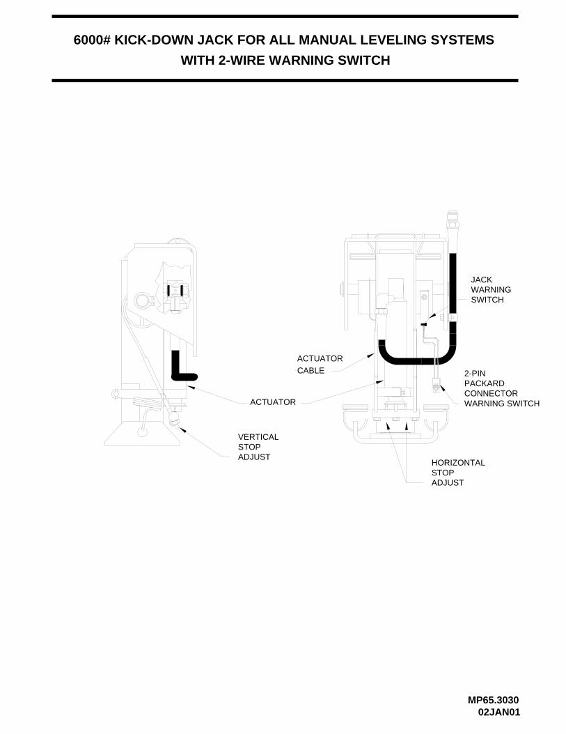
JACKWARNINGSWITCH
HORIZONTALSTOPADJUST
ACTUATOR
6000# KICK-DOWN JACK FOR ALL MANUAL LEVELING SYSTEMS
WITH 2-WIRE WARNING SWITCH
MP65.303002JAN01
ACTUATORCABLE
VERTICALSTOPADJUST
2-PINPACKARDCONNECTORWARNING SWITCH

9000# KICK-DOWN JACK FOR ALL MANUAL LEVELING SYSTEMS
WITH 2-WIRE WARNING SWITCH
JACK WARNINGSWITCH
HORIZONTALSTOPADJUSTMENT
ACTUATOR
VERTICALADJUSTMENT
ROLLERBEARING
MP65.303502JAN01
ACTUATORTUBE
2-PIN PACKARDCONNECTORWARNING SWITCH

JACKWARNINGSWITCH
HORIZONTALSTOPADJUST
VERTICALSTOPADJUST
ROLLERKIT
16000# KICK-DOWN JACK FOR ALL MANUAL LEVELING SYSTEMS
WITH 2-WIRE WARNING SWITCH
MP65.304002JAN01
ACTUATOR
2-PIN PACKARDCONNECTORWARNING SWITCH

STRAIGHT-ACTING JACK FOR ALL MANUAL LEVELING SYSTEMS
WITH 2-WIRE WARNING SWITCH
RETURN SPRINGS SIDE / SIDE
MP65.304502JAN01
WARNING SWITCHB
A
A
BA
WARNING SWITCH
B
2-WIRE PACKARDCONNECTORWARNING SWITCH
2-WIRE PACKARDCONNECTORWARNING SWITCH
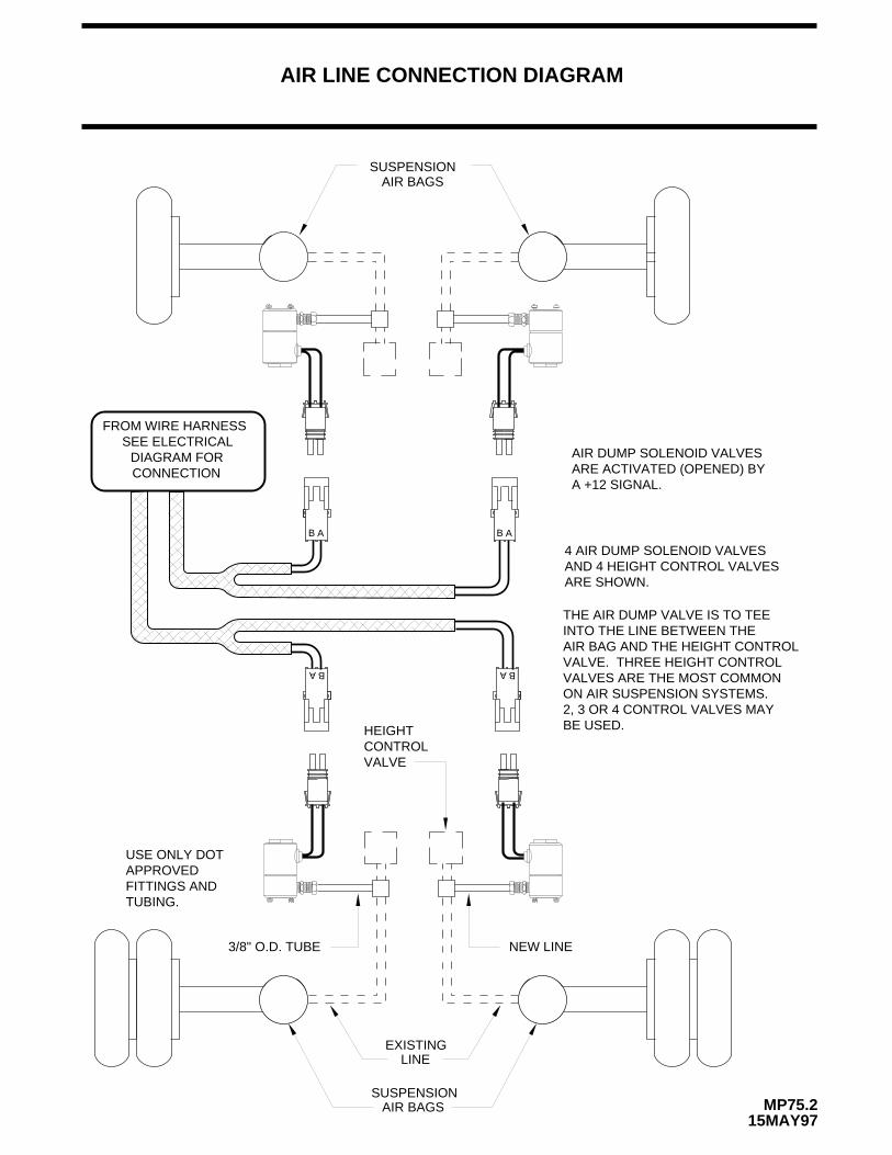
3/8" O.D. TUBE
SUSPENSION AIR BAGS
SUSPENSIONAIR BAGS
NEW LINE
AIR LINE CONNECTION DIAGRAM
MP75.215MAY97
EXISTINGLINE
4 AIR DUMP SOLENOID VALVESAND 4 HEIGHT CONTROL VALVESARE SHOWN.
THE AIR DUMP VALVE IS TO TEEINTO THE LINE BETWEEN THEAIR BAG AND THE HEIGHT CONTROLVALVE. THREE HEIGHT CONTROLVALVES ARE THE MOST COMMONON AIR SUSPENSION SYSTEMS.2, 3 OR 4 CONTROL VALVES MAY BE USED.
USE ONLY DOTAPPROVEDFITTINGS ANDTUBING.
HEIGHT CONTROLVALVE
AIR DUMP SOLENOID VALVESARE ACTIVATED (OPENED) BYA +12 SIGNAL.
SEE ELECTRICALDIAGRAM FORCONNECTION
FROM WIRE HARNESS
BA
AB
A B
AB

MP85.3016
ELECTRICAL CONNECTION DIAGRAM
MAKE ALL GROUNDINGCONNECTIONS BEFOREAPPLYING POWERTO BOX.
02FEB99
AB
ABA
TOUCHPANEL
(RED)
SENSINGUNIT
SEE CONTROL BOXELECTRICAL
(WHITE)
SWITCHHARNESS
RF
LR RR
310 LEVELING SYSTEM
CONNECTION
HYDRAULIC MANIFOLDHARNESS
TO JACKWARNINGSWITCH
TO JACKWARNINGSWITCH
HYDRAULIC MANIFOLDELECTRICAL CONNECTION
DIAGRAM
CONNECTION DIAGRAMGROUNDING ELECTRICAL
PUMP RELAY ELECTRICALCONNECTION DIAGRAM
LEVEL
B
(YELLOW)
(WHITE)
SEE MASTER WARNINGLIGHT/BUZZER CONNECTION
DIAGRAM
LF
#10 WIRE TO GROUND STUD - (WHITE) 6230
CONTROL - (BROWN) 7699
+12 - (PURPLE) 6121
SEE TOUCH PANELCONNECTIONDIAGRAM
SWITCHWARNINGTO JACK
A
A
B
AIR DUMPVALVE
A
ARE POSSIBLEVALVE ARRANGEMENTS
OTHER AIR DUMP
(GRAY) 9300
(WHITE) 6230
A
B
(WHITE) 6230
(GRAY) 9300
AIR DUMPHARNESS
(WHITE)
(GRAY)
SEE SUSPENSION AIRDUMP DIAGRAM FOR ADDITIONALEXPLANATION OF AIR DUMPVALVE CONNECTIONS
WARNING
WITH SUSPENSION AIR DUMP
TEE ADAPTOR
NOTE:
TOUCH PANELCABLE ASSEMBLY
A
B
BA
B
B
TO PARK BRAKESWITCH(LABELED) -9000
TO BRAKELIGHT ONDASH(LABELED) -9001
(BLUE)9000
FROM +12 ACC.FUSED 15 AMP MAX -(BROWN) 6120
9300
6230
6235
1000
2000
6235
(WHITE)6230(GRAY)9300
NOTE: THE (4) DIGIT WIRE NUMBERSUPERSEDES ANY AND ALL WIRECOLORS.
(BLACK)3000(WHITE)
6235
(WHITE)6235
(GREEN)4000

HWH HYDRAULIC LEVELING
UNDERSTAND OPERATOR’S MANUAL BEFORE USING. BLOCK FRAME AND TIRESSECURELY BEFORE REMOVING TIRES OR CRAWLING UNDER VEHICLE.
310 SERIES LEVELING SYSTEM TOUCH PANELCONNECTION DIAGRAM
WITH SUSPENSION AIR DUMP
ALL WIRE CONNECTIONS WILL POINTAWAY FROM THE PANEL WHEN PLUGGED IN.
8-CONTROL - (BROWN) 76997-+12 - (PURPLE) 6121
PIGTAILINDICATORWARNINGMASTER
9-BLANK
6-BLANK
NOTE:
5-STORE RETURN4-FUSED ACCESSORY3-SWITCHED ACCESSORY
(TO CONTROL BOX)2-FUSED ACCESSORY(TO CONTROL BOX)
8-DUMP7-GROUND6-PARK BRAKE
OFF
DUMPSTORE
PARK/NOT IN
BRAKE
CAUTION!
ON
INPUTSSWITCHWARNING
MP85.301721OCT99
CABLE CONNECTIONS
THE (4) DIGIT WIRENUMBER SUPERSEDESANY AND ALL WIRE COLORS.
4-LEFT FRONT - (YELLOW) 1000
NOTE:
5-COMMON - (WHITE) 6235
RED-REAR-1
BLACK-FRONT-3
TOUCH PANEL
3-RIGHT FRONT - (RED) 20002-RIGHT REAR - (BLACK) 3000 1-LEFT REAR - (GREEN) 4000
GREEN-RIGHT SIDE-2
YELLOW-LEFT SIDE-4WHITE-COMMON-5
INPUTS
SENSINGLEVEL
UNIT
LEFT FRONT-11LEFT REAR-12RIGHT REAR-13KEY N.C.-14RIGHT FRONT-15
STORE-9PUMP-10
1-JACK DOWNWARNINGSENSOR

5 AMP
10 A
MP
10 A
MP
10 A
MP
5 A
MP
RIGHT FRONT FUSE
PART NUMBER AND
10 A
MP
LEFT FRONT FUSE
TOUCH PANELCABLE INPUT
MP85.302406APR99
ROOM EXTENSIONPUMP CONTROL(ONLY USED
ROOM EXTENSION)
15 PIN
CONNECTION LABEL
TOUCH PANEL CABLESLIDE OUT
SWITCH
AND SERIAL NUMBER
WITH HWH
6-PARK BRAKE7-GROUND8-DUMP9-STORE10-PUMP11-LEFT FRONT12-LEFT REAR13-RIGHT REAR14-BLANK15-RIGHT FRONT
5 - STORE RETURN4 - FUSED ACCESSORY(TO TOUCH PANEL)3 - SWITCHED ACCESSORY(FROM TOUCH PANEL)2 - FUSED ACCESSORY(FROM TOUCH PANEL)
FROM +12 ACC. - (BROWN) 6120
PUMP FUSE
JACK INTERRUPT FOR ROOM EXTENSION(IF NEEDED)
1 - JACK DOWNWARNING SWITCH
ELECTRICAL CONNECTION DIAGRAMCONTROL BOX
310 SERIES LEVELING SYSTEMWITH SUSPENSION AIR DUMP
RIGHT REAR FUSE
7.5 AMP
DUMP FUSE
LEFT REAR SOLENOID VALVE -(BROWN) 4400
RIGHT FRONTSOLENOID VALVE -(GREEN) 2400
LEFT FRONTSOLENOID VALVE -(BLUE) 1400
DUMP - 9300
LEFT REAR FUSEPUMP - (GRAY) 8600
#10 POWER WIRE -(BLACK) 6100
PARK BRAKE -(BLUE) 9000
ACC. FUSE
#10 GROUND WIRE -(WHITE) 6230(TWO WHITE WIRESIN THE RING TER-MINAL WHEN AIRDUMP IS USED)
PRESSURESWITCH -(BLACK) 8100
RIGHT REARSOLENOID VALVE -(ORANGE) 3400
NOTE: THE (4) DIGIT WIRE NUMBERSUPERSEDES ANY AND ALL WIRE COLORS.

ELECTRICAL SCHEMATIC
08JAN97
ON / OFF CIRCUIT
310 LEVELING SYSTEM
MP85.3031
4 2 3
CR1
CR1-1
CONTROL BOX
+12 ACC
5 AMP
TOUCHPANELCABLE
TOUCH PANELON LIGHT
324
ON
OFF

MP85.303302FEB99
PUMP RELAY
VIEW FROM TANK END
MANIFOLD DIAGRAM
+
GROUND
BATTERY
(WHITE) 6231
PUMP MUST BE MOUNTED SOLIDLY TO FRAME. SOME PUMPS HAVE AGROUND CABLE THAT IS TO BE ATTACHED TO THE GROUND STUD.
* FUSE
* FUSE MAY BE REQUIRED - CHECK APPLICABLE CODE
FRAME, USE THE GROUND STUD TO ATTACH THETHE PUMP TO THE BRACKET. IF THE PUMP BRACKETIS BOLTED TO THE FRAME, USE THE GROUND STUDTO ATTACH THE BRACKET TO THE FRAME.
-
(GRAY) 8600
PUMP/MANIFOLDHARNESS
(BLACK) 6100
AB
RR RF LF LR
PRESSURE SWITCH (50 PSI)DO NOT REVERSE WIRE
COLORS TO A & B ONPACKARD CONNECTORS
310 LEVELING SYSTEMHYDRAULIC MANIFOLD-PUMP RELAYELECTRICAL CONNECTION DIAGRAM
SEE GROUNDING INSTRUCTION DIAGRAM
NOTE : IF THE PUMP BRACKET IS WELDED TO THE
B A AB B A
(MAY BE IN ADIFFERENTLOCATION)
FUSE40AMP
PUMP RELAY
4
3
1
2
PUMP/MANIFOLDHARNESS (O
RA
NG
E)
3400
(WH
ITE
) 62
40
(GR
EE
N)
2400
(WH
ITE
) 62
41
(BLU
E)
1400
(WH
ITE
) 62
40
(BR
OW
N)
4400
(WH
ITE
) 62
41
(BLA
CK
) 81
00
NOTE: THE (4) DIGIT WIRE NUMBERSUPERSEDES ANY AND ALL WIRECOLORS.
NOTE: THE (4) DIGIT WIRE NUMBERSUPERSEDES AY AND ALL WIRE COLORS.

+-
(3 USED)
USE GROUNDING STUD AND 3/8" INTERNALSTAR LOCKWASHERS AS SHOWN.
PUMP MOUNTING
GROUND CABLESTRAP
3/8 -16 NUT
FRAME RAIL
(2 USED)
CABLESTRAP
GROUND
3/8" INT. STAR LOCKWASHER
GROUNDING STUD
PUMP MOUNTINGPOSITIONS.
PUMP/MANIFOLD HARNESS
GROUP OF WHITEWIRES 6 INCHES FROMEND OF LOOM TO BE
(NOT USEDON SOME PUMPS)
(NOT USEDON SOME PUMPS)
-
GROUNDED TO STUD.
WIRES 6 INCHES FROMGROUP OF WHITE
GROUNDED TO STUD.END OF LOOM TO BE
+
WELDED PUMP MOUNT
SURFACE AND WIRE TERMINALSMUST BE USED BETWEEN GROUNDINGIMPORTANT: STAR LOCKWASHER
PUMP
HARNESSMANIFOLD
PUMP MOUNTED REMOTEFROM FRAME
3/8" INT. STAR LOCKWASHER(4 USED)
GROUNDSTUD
STAR LOCKWASHERS AS SHOWN.USE GROUNDING STUD AND 3/8" INTERNAL
STAR LOCKWASHER MUST BE USED BETWEEN GROUNDINGSURFACE AND WIRE TERMINALS.
IMPORTANT:
310/325 LEVELING SYSTEM POWER UNIT/HARNESS
GROUNDING INSTRUCTIONS
MANIFOLD GROUND
PUMP RELAY ELECTRICALCONNECTION DIAGRAM
SEE HYDRAULIC MANIFOLD/
CONNECTION DIAGRAMPUMP RELAY ELECTRICAL
MANIFOLD GROUNDSEE HYDRAULIC MANIFOLD/
CHANNEL
(WHITE) 6233(WHITE) 6240(WHITE) 6241(WHITE) 6230(WHITE) 62313/8-16 NUT
NOTE: THE (4) DIGIT WIRE NUMBERSUPERSEDES ANY AND ALL WIRE COLORS.
6233
(WHITE) 6240(WHITE) 6241(WHITE) 6231(WHITE) 6230
NOTE: THE (4) DIGIT WIRE NUMBERSUPERSEDES ANY AND ALL WIRE COLORS.
ELECTRICAL CONNECTION DIAGRAM
MP85.304312MAY03

CONNECT THIS ENDTO IGNITION "ON" POWER
5-15 AMP FUSE
+ _
BUZZER
DO NOT USE PURPLEWIRE. REMOVE PURPLE WIREFROM MTA CONNECTOR
SPLICE BROWN WIRE FROMHWH LIGHT PLATE TO BROWNPIGTAIL WITH BUTT CONNECTOR
SEE TOUCH PANEL CONNECTION
DIAGRAM
+12 - (PURPLE) 6121
CONTROL WIRE - (BROWN) 7699
WARNING LIGHT WIRES ARE PLUGGEDDIRECTLY INTO THE TOUCH PANEL
+-
MASTER LIGHT/BUZZER CONNECTION DIAGRAMMANUAL LEVELING SYSTEMS
CAUTION:THE PURPLE WIRE IN THE MASTER WARNING LIGHT PIGTAIL IS HOT WHENEVER THE IGNITIONIS "ON" OR IN "ACC". THE PURPLE WIRE MUST BE REMOVED FROM THE PIGTAIL WHEN USING DIRECT IGNITIONVOLTAGE FOR THE MASTER WARNING INDICATORS.
FIGURE 1
FIGURE 2
310 SERIES
SEE TOUCH PANEL
DIAGRAMCONNECTION
NOTE:
JACKS DOWNLIGHT INCLUDEDIN HARDWARE KIT
MP85.305310OCT02
A MASTER WARNING INDICATOR SHOULD ALWAYS BE USED. WHEN THE LEVELING SYSTEM HAS STRAIGHT-ACTINGJACKS A WARNING BUZZER MUST BE USED.
WHEN ONLY A RED MASTER WARNING LIGHT IS USED THE +12 POWER FOR THE LIGHT COMES THROUGH THE TOUCHPANEL. (SEE FIGURE 1 BELOW.) WHEN BOTH A RED LIGHT AND WARNING BUZZER ARE USED THE +12 POWER FORBOTH INDICATORS IS SUPPLIED BY THE IGNITION SWITCH. THE POWER MUST COME FROM THE "ON" SIDE OF THEIGNITION SWITCH, NOT THE "ACC" SIDE. (SEE FIGURE 2 BELOW.)
NOTE: BY SUPPLYING IGNITION POWER TO THE WARNING BUZZER AND LIGHT, AND "ACC" POWER TO THE CONTROLBOX, THE SYSTEM MAY BE OPERATED IN ACCESSORY WITHOUT THE BUZZER SOUNDING. THE NEGATIVE SIGNALFOR THE WARNING INDICATORS MUST ALWAYS COME FROM THE TOUCH PANEL.
NOTE: THE (4) DIGIT WIRE NUMBERSUPERSEDES ANY AND ALL WIRE COLORS.
PIGTAIL W/DIODEAND IN-LINE FUSE HOLDER -(PURPLE) 6121
PIGTAIL PROVIDED -(BROWN) 7699
NOTE: THE (4) DIGIT WIRE NUMBERSUPERSEDES ANY AND ALL WIRE COLORS.
12V

LOCKING NUT
PRESSURE ADJUSTBODY
PRESSURE SWITCH
ADJUSTMENT COMPONENT IDENTIFICATION
MP85.510527JUN01
RUBBER BOOT