kgcoe msd p15263 - rochester institute of technologyedge.rit.edu/content/p15261/public/final...
TRANSCRIPT

10/27/2015
KGCOE MSD P15261
Revision 7
Pg 1 / 44
KGCOE MSD P15261
Offboard Electric Vehicle Charger
Joseph Droleskey, Tucker Graydon, Brian Hebbard, Christopher Liess

10/27/2015
KGCOE MSD P15261
Revision 7
Pg 2 / 44
Index
Customer Project Readiness Package (PRP) 3
Customer Requirements 7
Engineering Requirements 8
Benchmarking 10
Risk Management 12
Morphological Table 15
Functional Decomposition 15
Team Schedule 16
System Layout and Design 27
AC-DC Rectification Subsystem 30
DC-DC Control Subsystem 32
Current Control Subsystem 34
Control and Logic System 35
CAN Communication Subsystem 36
Microcontroller 38
Prototype CAD Design 42
Estimated Bill of Materials 43
References 44

10/27/2015
KGCOE MSD P15261
Revision 7
Pg 3 / 44
Multidisciplinary Senior Design
Project Readiness Package
Project Title: Electric Superbike Off-board Charger
Project Number:
(MSD will assign this) P15261
Primary Customer:
(provide name, phone
number, and email) EVT, Josh Jones, Wheeler Law, Derek Gutheil
Sponsor(s):
(provide name, phone
number, email, and amount
of support)
MSD Senior Design department
Preferred Start Term: Spring 2015
Faculty Champion:
(provide name and email) Prof. George Slack, [email protected]
Other Support:
Project Guide:
(MSD will assign this) Slack
EVT, Josh Jones, Derek Gutheil January 2015
Prepared By Date

10/27/2015
KGCOE MSD P15261
Revision 7
Pg 4 / 44
Project Information
Overview: The RIT Electric Vehicle Team is a student run organization dedicated to promoting the
viability of electric vehicles through real world demonstrations of electric drivetrains in action. The
team aims to educate people on the principles of electric vehicle design by engaging students in
challenging and rewarding projects that cover a wide variety of academic disciplines. The team’s main
project is to design, build, and race a high performance electric motorcycle for competition in the 2015
eMotoRacing all-electric race series. The current bike is based off of the frame from a 2005 Kawasaki
Ninja ZX6RR, and utilizes two Zero Z-Force 75-7 motors paired with two Sevcon Size6 controllers. In
house engineering includes the design and fabrication of a battery management system, battery
containment modules, structural framing for the mounting of the powertrain, as well as advanced data
collection and analysis software. Based on this, the team is currently in need of a high powered charger
that can charge the bike's battery pack in a reasonable amount of time.
Project Goals: The R.I.T. Electric Vehicle Team proposes a portable off-board charger for an electric super
bike. In order to compete in the E-Moto Racing series, the team requires an efficient and reliable
method of charging the bike's 12 Kwh battery pack. Unlike traditional battery chargers, the superbikes
charger must conform to the J-1772 electric vehicle charging standard.
References:
[1] http://emotoracing.com
[2] http://en.wikipedia.org/wiki/SAE_J1772
[3] https://code.google.com/p/open-evse/wiki/J1772Basics
[4] http://batteryuniversity.com/learn/article/charging_lithium_ion_batteries
Customer Requirements (CR): This list of customer requirements of anticipated activities.
CR # Imp. Customer Need Description
CR1 1 Battery connection Able to safely connect and discount battery.
CR2 1 Power on / off Able to safely power on and power off charger
CR3 4 LCD Display Able to know the charging rates, state of charge,
charging time, etc. CR4 3 Adjustable Able to select voltage and current

10/27/2015
KGCOE MSD P15261
Revision 7
Pg 5 / 44
CR5 1 J-1772 standard Able to implement given standard(s)
CR6 3 Communication with the Superbike Able to communicate with the Superbike's BMS
via CAN
CR7 1 Wall connection Able to charge via J-1772 or 120V Wall
connection
CR8 3 Documentation
Every facet of the project must be well
documented with instructions where
necessary
CR9
CR10
Engineering Requirements (ER):
1. Power Requirements
a. The charger must be capable of charging a battery from full discharge to full charge in
no more than 4 hours while using the J-1772 standard charging station
b. The charger must also be capable of operating through standard 120V 15A 60Hz wall
outlets. While in this low power mode, the charger must be capable of charging the
battery in no more than 12 hours
c. The charging system must automatically detect and switch between the low and high
power modes
2. Control Requirements
a. The charger must be able to output voltage and current to within 20% of the nominal
values in either mode. These outputs must also be regulated to within 1% of their set
values
b. The charger must be able to vary voltage and current through both software and a user
interface
3. Communication Requirements
a. Needs to conform to the J-1772 communication protocol for use in high power mode
b. During all modes of operation, the charger must be capable of communicating over
CAN
Constraints: Safety is of the upmost importance. It will be a factor in every aspect of the design. The
batteries on the Superbike that will be charged have a large capacity, and as such, will not be readily
available for testing. The Electric Vehicle Team has access to them and can provide them upon request.
Most EVT members can be made available with a reasonable notice for assistance. EVT members will
also be a regular part of the design process ensuring that their goals are met.
Project Deliverables: Minimum requirements:

10/27/2015
KGCOE MSD P15261
Revision 7
Pg 6 / 44
● All design documents (e.g., concepts, analysis, detailed drawings/schematics, BOM, test
results)
● working prototype
● technical paper
● poster
Additional required deliverables:
● List here, if applicable
Budget Information: List major cost items anticipated, and any special purchasing requirements from the sponsor(s).
Intellectual Property: There are no IP restrictions on this project

10/27/2015
KGCOE MSD P15261
Revision 7
Pg 7 / 44
Customer Requirements
CR # Imp. Customer Need
CR1 1 Battery Connection to charger meets safety standards
CR2 1 Power on / off
CR3 4 LCD Display
CR4 3 Adjustable Outputs
CR5 1 J-1772 standard
CR6 3 Communication with the Superbike
CR7 1 Wall Connection
CR8 3 Documentation
CR9 1 Overall Design must be User Safe
CR10 1 Monitoring of battery charging
CR11 1 Adhering to EVT safety protocols
CR # Description
CR1 Able to safely connect and disconnect battery
CR2 Able to safely power on and power off charger
CR3 Able to know the charging rates, state of charge, charging time, etc
CR4 Able to select voltage, current
CR5 Able to implement given standard(s)
CR6 Able to communicate with Superbike's BMS via CAN
CR7 Able to charge via J-1772 or 120V wall connection
CR8 Every facet of project must be well documented with instruction where necessary
CR9 The final implementation must be safe to use even for a person who has never been trained on it
CR10 The charger must monitor the battery status over CAN communication to prevent damage to
battery
CR11 While working on the charger and with the batteries the team must adhere to all the safety
protocols the Electric Vehicle Team has in place and a member of EVT must always be present.

10/27/2015
KGCOE MSD P15261
Revision 7
Pg 8 / 44
Engineering Requirements & Specifications (revision 4)
Some features have been omitted since they do not necessarily have engineering metrics to rate success. These features include the user
interface being simple and user friendly, Certain safety implementations such as key switches and emergency stops. These are addressed in
the respected subsystem documentation.

10/27/2015
KGCOE MSD P15261
Revision 7
Pg 9 / 44
Specifications
Below are the current specifications for the charger: They currently based on the XALT 63 Ah High Power LIPO Cells in a pack of 25
connected in series. The list will be continuously updated as more data becomes available.
Parameter Min Expected Max Unit Comments
UnderVoltage Lockout 2.6 V Bat. Too low
Charge Current 1 15 50 A Depends on Source
Charge Voltage 25 50 110 V Pack Size dependent
Battery Termination Voltage 4.1 V
Accuracy -1 0 1 %
Battery Overvoltage Threshold 0.1 V
Battery Detection 2.5 2.9 4 V
Battery Detection Timer 333 ms
Start Charging Delay Timer 1 min
Charge Complete Timer 5 min
Safety Timer 2910 35 min Based on Charge Param.

10/27/2015
KGCOE MSD P15261
Revision 7
Pg 10 / 44
Benchmarking
PARAMETERS
Required EVT Energica Ego
Charge Rate <4hrs Charge Rate <4hrs 3.5hrs
Cool Rate 40deg C stability Cool Rate 40deg C stability Not Specified
PWR Response 1 sec PWR Response 1 sec Not Specified
Capacity 11.544 kWh Capacity 11.544 kWh 11.7 kWh
Life 1200 CYCLES Life 1200 CYCLES 1200 CYCLES
V/I Reg. Accuracy >99% CFM TBD 90
Output Voltage 50-60V+ 110/220V
Cost <$1000 >$1000
Attached Below is a expanded graph of efficiency and voltage characteristics of other EV Chargers
analyzed by EnergyStar for approval. These values will be used to compare the end product with what
is on the market currently.

10/27/2015
KGCOE MSD P15261
Revision 7
Pg 11 / 44

10/27/2015
KGCOE MSD P15261
Revision 7
Pg 12 / 44
MSD Risk Assessment
ID Risk Item Effect Cause Lik
elih
oo
d
Sev
erit
y
Imp
ort
an
ce
Action to Minimize Risk Owner
Describe the risk briefly What is the effect on any or all of the project deliverables if the cause actually happens?
What are the possible cause(s) of this risk?
L*S What action(s) will you take (and by when) to prevent, reduce the impact of, or transfer the risk of this occurring?
Who is responsible for following through on mitigation?
1
J-1772 interface unobtainable
The charger will not be usable with J-1772 chargers unless an adapter is manufactured in house
IP restrictions/low demand or supply for the interface
1 6 6 Conduct proper research into the ability to purchase this interface
Team
2 Over current
Damaged equipment,
injured
operator/bystander Current regulation does
not work 1 9 9
Researching and developing a
safety mechanism that shuts down
the charger and electrical system
when failure is detected Team
2 Over current
Damaged equipment,
injured
operator/bystander Software fails to detect
current 1 9 9 Debugging code and perform
testing Team
3
Battery management
system fails to cut off the
charge
Batteries
overcharge/lifecycle
decreases
Microcontroller fails to
detect a full
battery/communication
disconnect 3 7 21
Thorough debugging of
code/firmware will be
implemented, a microcontroller that
can effectively communicate with
the BMS will be researched and
purchased. Use test equipment to
ensure that the battery cells will not
exceed or meet 100% capacity Team
4 Input voltage detection Batteries Damaged
Microcontroller/software
fails to detect input
voltage 1 7 7
Thorough debugging of
code/firmware will be
implemented, a microcontroller that
can effectively communicate with
the BMS will be researched and Team

10/27/2015
KGCOE MSD P15261
Revision 7
Pg 13 / 44
purchased
5 Damage to charger
Must replace damaged
equipment/increased
cost due to replacement
Improper use,
overheating, system
design, short circuit 2 9 18
Implementation of redundant safety
systems and procedures. Adequate
research and testing to validate
design Team
6 Design Over-Budget Not all components are
obtainable
Lack of oversight,
incorrect parts ordered,
replacement to damaged
parts 2 7 14
Keep a log of desired
items/components, assign an
estimate cost to each system, and
minimize risk 5. Team/Project
Manager
7 Design behind schedule Project deliverables
incomplete
Unforeseen design
complications, Risk 5,
Lack of communication
between team 3 5 15
Team must update/adhere to
schedule on a regular basis and
maintain communication of any
possible complications or FMEA’s Project
Manager/Team
8 System function fails test Function must be
corrected
Inadequate components
within system, not
designed to interface
with other functions 2 6 12
Adequate research will minimize
risks. Having multiple concepts per
subsystem/function will provide a
backup in case system is proven to
fail. Team
9 System overheats Damaged Equipment Inadequate cooling 2 6 12 Add sufficient vents, fans, and heat
sinks. Team
9 System overheats Damaged Equipment Software does not detect
temperature 1 6 6
Debugging code and perform
testing to determine sensor is
recording accurate values Team
10 Battery Cell Detection Damaged Batteries Software does not detect
correct number of cells 1 6 6
Debugging code and perform
testing to determine code is
recording accurate values Team
11 Output Voltage Detection Damaged Batteries Software does not detect
correct output voltage 1 6 6
Debugging code and perform
testing to determine code is
recording accurate values Team
Likelihood scale Severity scale 1 - This cause is unlikely to happen 1 - The impact on the project is very minor. We will still meet deliverables on time and within budget, but it
will cause extra work

10/27/2015
KGCOE MSD P15261
Revision 7
Pg 14 / 44
2 - This cause could conceivably happen 4 - The impact on the project is noticeable. We will deliver reduced functionality, go over budget, or fail to
meet some of our Engineering Specifications.
3 - This cause is very likely to happen 9 - The impact on the project is severe. We will not be able to deliver, or what we deliver will not meet the
customer's needs.
“Importance Score” (Likelihood x Severity) – use this to guide your preference for a risk management strategy
Prevent Action will be taken to prevent the cause(s) from occurring in the first place.
Reduce Action will be taken to reduce the likelihood of the cause and/or the severity of the effect on the project, should the cause
occur
Transfer Action will be taken to transfer the risk to something else. Insurance is an example of this. You purchase an insurance
policy that contractually binds an insurance company to pay for your loss in the event of accident. This transfers the
financial consequences of the accident to someone else. Your car is still a wreck, of course.
Accept Low importance risks may not justify any action at all. If they happen, you simply accept the consequences.

10/27/2015
KGCOE MSD P15261
Revision 7
Pg 15 / 44
Morphological Table
Functional Decomposition

10/27/2015
KGCOE MSD P15261
Revision 7
Pg 16 / 44
Team Schedule
MSD II Schedule (Fall 2151) (updated 8/19/2015)
Class Date Phase Activities Week # Dates Team Members
All
semester
Build/ Test/
Integrate/Modify:
Sub-system &
System Level
Iterative activities throughout
semester
- Build/Test/Integrate/Modify.
Update Test Plan.
- Planning and tracking,
including risk assessment and
problem list
- Logbook updates
- Documentation and upload to
EDGE
Brian Hebbard Chris Liess Tucker Graydon Joe Droleskey
1
Wk 1
Aug 25
(Tues)
Subsystem Level
Prep/Build
Design Completion
(if failed gate
review)
Class:
MSD II Expectations: first 2
weeks and end of semester.
Revisit “Big Picture”.
Point students to purchasing
resources, space requests,
fabrication resources, safety
DeBartolo
MSD I post-mortem, project
planning, problem solving
Project plan walk-through with
Guide
1 8/24/2015
Catch team up on project status and goals, develop weekly meeting time outside of MSD II
Review project documentation
Review project documentation
Review project documentation

10/27/2015
KGCOE MSD P15261
Revision 7
Pg 17 / 44
2
Wk 1
Aug 27
(Thurs)
Online module: Testing
resources (test bench setup)
– equipment procurement,
location, procedures and exit
criteria, responsibilities,
schedule & priorities -- ready
to implement tests. (30 min)
Class:
Test plan walk-through with
Guide (each team member
brings in drafttest plan for
select ER's after watching
module)
3
Wk 2
Sept 1
(Tues)
Subsystem Level
Prep/Build
Design Completion
(if failed gate
review)
Status update, Phase I:
schedule for testing, what will
you demo in weeks 5, 8, and
11? (Revisit at each demo).
Review Team plan for Week 5
Subsystem Demo
Critical Design Review (some
teams - if failed gate review):
finalize design, demo key
functions, updated project
plan, test plan, other action
items
2 8/31/2015
Update schedule. Review progress of hardware, software and firmware development
Update BOM Update BOM Update BOM

10/27/2015
KGCOE MSD P15261
Revision 7
Pg 18 / 44
4
Wk 2
Sept 3
(Thurs)
Status update, Phase I:
schedule for testing, what will
you demo in weeks 5, 8, and
11? (Revisit at each demo).
Review Team plan for Week 5
Subsystem Demo
Critical Design Review (some
teams - if failed gate review):
finalize design, demo key
functions, updated project
plan, test plan, other action
items
Order components.
Order components Order components
5
Wk 3
Sept 8
(Tues)
Build/Test: Sub-
system Level
3 9/7/2015 Prepare team for "Milestone Review" #1
6
Wk 3
Sept 10
(Thurs)
Milestone Review #1
Researched means of reducing overall cost by investing in PCB alternatives.
Researched means of reducing overall cost by investing in PCB alternatives.
Researched means of reducing overall cost by investing in PCB alternatives.
Researched means of reducing overall cost by investing in PCB alternatives.
7
Wk 4
Sept 15
(Tues)
Build/Test: Sub-
system Level
4 9/14/2015

10/27/2015
KGCOE MSD P15261
Revision 7
Pg 19 / 44
8
Wk 4
Sept 17
(Thurs)
Ensure that Edge content is up to date, review results from software and hardware testing
9
Wk 5
Sept 22
(Tues)
Build/Test: Sub-
system Level
(Functional Demo)
Sub-System Functional Demo
(key subsystems):
Demonstrate subsystem
functionality
Report out on test results
Updates to project plan,
problem solving, and team
goals for Week 8 demo
5 9/21/2015
Begin building prototype, full-scale DC-DC voltage/current regulation system
10
Wk 5
Sept 24
(Thurs)
Sub-System Functional Demo
(key subsystems):
Demonstrate subsystem
functionality
Report out on test results
Updates to project plan,
problem solving, and team
goals for Week 8 demo
Finish building prototype DC-DC voltage/current regualtion system, begin contstructing test setup
Finish building prototype DC-DC voltage/current regualtion system, begin contstructing test setup
Finish building prototype DC-DC voltage/current regualtion system, begin contstructing test setup
11
Wk 6
Sept 29
(Tues)
Build/Test/
Integrate: Sub-
system & System
Level
6 9/28/2015 Prepare team for "Milestone Review" #2
Test DC-DC voltage/current regulation system in an isolated test setup, compile and report on test results
Test DC-DC voltage/current regulation system in an isolated test setup, compile and report on test results
Test DC-DC voltage/current regulation system in an isolated test setup, compile and report on test results

10/27/2015
KGCOE MSD P15261
Revision 7
Pg 20 / 44
12
Wk 6
Oct 1
(Thurs)
Milestone Review #2
Begin developing software and firmware framework, confirm that the framework allows the Teensy to boot
13
Wk 7
Oct 6
(Tues)
Build/Test/
Integrate: Sub-
system & System
Level
Troubleshooting at the system
integration level: the
subsystems did what they were
supposed to but system doesn’t
work when it’s put together,
OR it works when I put it all
together but not as well as it
should. Open Q&A -
depending on demand, will use
a classroom or Design Center.
7 10/5/2015
Review test/inspection results, address any anomolies/failures, ensure that Edge content is up to date
Purchase capacitors for AC-DC system
Continue developing software and firmware, adding initial menus to the UI
14
Wk 7
Oct 8
(Thurs)
Purchase plexiglass
Continue developing software and firmware, adding menus to the UI. Create PCB for the gate driver
Purchase plexiglass
Wk 8
Oct 13
(Tues)
Fall Break - no class - follow
Monday schedule today - no
MSD
8 10/12/2015
Review test/inspection results, address any anomolies/failures, ensure that Edge content is up to date
Create layout of AC-DC voltage regulation system
Continue developing software and firmware, adding menus to the UI, charge selection menu.
Purchase PVC pipe to use as spacers

10/27/2015
KGCOE MSD P15261
Revision 7
Pg 21 / 44
15
Wk 8
Oct 15
(Thurs)
Spec out possible "project box" based on size of the PCB
Start building prototype AC-DC voltage regualtion system
Continue developing software and firmware, adding warning messages and flags
Begin building high current Rev. 2 of the DC-DC voltage/current regulation system, with the test results driving any design changes
16
Wk 9
Oct 20
(Tues)
Build/Test/
Integrate: Sub-
system & System
Level
Preliminary Integrated
System Demo (probably w/o
Customer) (all subsystems,
some integration).
Demonstrate any remaining
subsystem functionality
Demonstrate preliminary
systems integration demo
Report out on test results
Updates to project plan,
problem solving, and team
goals for Week 11 demo with
customer
9 10/19/2015 Prepare team for "Milestone Review" #3
Finish building prototype AC-DC voltage regualtion system, begin contstructing test setup
Continue developing software and firmware, adding key functions (charge rate, etc)
Finish building high current Rev. 2 of the DC-DC voltage/current regulation system

10/27/2015
KGCOE MSD P15261
Revision 7
Pg 22 / 44
17
Wk9
Oct 22
(Thurs)
Preliminary Integrated
System Demo (probably w/o
Customer) (all subsystems,
some integration).
Demonstrate any remaining
subsystem functionality
Demonstrate preliminary
systems integration demo
Report out on test results
Updates to project plan,
problem solving, and team
goals for Week 11 demo with
customer
Milestone Review #3
Purchase container for charger
Test AC-DC voltage regulation system in an isolated (from other subsystems) test setup, compile and report on test results
Develop and ensure that methods of communicating over CAN are robust and functioning properly, load firmware Rev. 1 onto the PIC, test key software functionality, report on results of testing
Mount PCB, relays and other subsystems that aren't on the PCB to the project box
18
Wk 10
Oct 27
(Tues)
Build/Test/
Integrate: System
Level
10 10/26/2015
Develop a user's manual for the charger that can be easily understood
Begin building Rev. 2 of the AC-DC voltage regulation system, with the test results driving any design changes
Continue developing software and firmware, adding remaining features (per ER and CR)
Consult with and assist Brian in developing hardware guidelines for a user's manual for the charger
19
Wk 10
Oct 31
(Thurs)
Consult with and assist Brian in developing software guidelines for a user's manual for the charger
Begin debugging any known non-functional key software/firmware features
Mount lock & key system to the project box

10/27/2015
KGCOE MSD P15261
Revision 7
Pg 23 / 44
20
Wk 11
Nov 3
(Tues)
Build/Test/
Integrate: System
Level
11 11/2/2015 Start paper.
Assist in developing hardware and software test procedures, taking into consideration ER and CR
Finish debugging known non-functional key software/firmware features, begin debugging known UI issues
Conduct a read-over of the user's manual to ensure that the manual could be easily understood
21
Wk 11
Nov 5
(Thurs)
22
Wk 12
Nov 10
(Tues)
Build/Test/
Integrate: System
Level
Full integrated system demo
with Customer.
System Demo with customer
Report out on final testing vs
ER's
Updates to project plan,
problem solving, and team
goals for Week 14 prototype
handoff with customer
12 11/9/2015 Continue to develope paper.
Verify via "dry-runs" that developed software and hardware test procedures are robust, testing all key subsystems sufficiently
Begin finalizing software and firmware development
Verify via "dry-runs" that developed software and hardware test procedures are robust, testing all key subsystems sufficiently
23
Wk 12
Nov 12
(Thurs)
Full integrated system demo
with Customer.
System Demo with customer
Report out on final testing vs
ER's
Updates to project plan,
problem solving, and team
goals for Week 14 prototype
handoff with customer

10/27/2015
KGCOE MSD P15261
Revision 7
Pg 24 / 44
24
Wk 13
Nov 17
(Tues)
Verification &
Validation
Submit 75% paper to
myCourses dropbox by today
- will be printed for
Thursday's workshop. 13 11/16/2015
Ensure that Edge content is up to date. Submit 75% paper.
Conduct software tests, cycling through various test procedures to ensure that all features work as intended
Address issues found via software and hardware testing
Conduct hardware tests, cycling through various test procedures to ensure that all features work as intended
25
Wk 13
Nov 19
(Thurs)
Technical Paper Workshop
9am (75% of paper complete)
DeBartolo
KGCOE Ethics Survey in-
class
26
Wk 14
Nov 24
(Tues)
Verification &
Validation
14
11/23/2015 Time delegated for addressing any possible last-minute anomolies/setbacks encountered during previous weeks
Wk 14 Nov 26
(Thurs)
Thanksgiving Break--NO
CLASS Thanksgiving Break
27
Wk 15
Dec 1
(Tues) 15 11/30/2015 Prepare for final presentation
28
Wk 15
Dec 3
(Thurs)
Verification &
Validation
Project complete – hand-off
obligations to Customer are
met
Final demo and customer hand-
off
Work space cleanup
Website complete
Post-mortem: team self-
assessment against norms &
values; objective evaluation of
successes & failures

10/27/2015
KGCOE MSD P15261
Revision 7
Pg 25 / 44
29
Wk 16
Dec 8
(Tues)
Project complete – hand-off
obligations to Customer are
met
Final demo and customer hand-
off
Work space cleanup
Website complete
Post-mortem: team self-
assessment against norms &
values; objective evaluation of
successes & failures
Paper complete
(SUGGESTED)
16
12/7/2015 Final Presentations
30
Wk 16
Dec 10
(Thurs) Presentations
Final Project Presentations
Papers due to Design Center
Office
Final Presentation
Exams Dec 14-
18 Gate Review
Gate Review - schedule by
team with guide:
Post mortem
Review EDGE
Check in locker/cart/cubicle to
Design Center Office

10/27/2015
KGCOE MSD P15261
Revision 7
Pg 26 / 44
(page inserted for future updates to schedule)

10/27/2015
KGCOE MSD P15261
Revision 7
Pg 27 / 44
System Design
Subsystems Covered:
1. Power Switch & Key
2. J1772 Inlet
3. AC/DC Rectifier System
4. Voltage Control System
1. DC-DC Controller
2. Current Limiter
3. Output
5. User Interface
6. MicroController
7. CAN Bus
8. Emergency Systems
1. Relays
2. J1772 Shutoff
9. Temperature Control
10. Programing Interface
1. Power Switch and Key
Both the Key and the Switch are need to turn on the overall charger system. A Master key is utilized to arm the
switch to be toggled on, this is done so that no unauthorized personnel have access to the charger. The switch turns the
power for the logic circuit on so that the user may begin interfacing with the charger.
2. J1772 Inlet
This is the female socket for the J1772 to plug into. A pilot signal from the microcontroller is needed to engage the
plug and allow it to conduct. There is a proximity pin on the line in that the logic circuit pulls its power from. This
proximity line sources approximately 12v.
3. AC/DC Rectifier System
Once the J1772 line has been engaged a differential phase AC current flows to the AC/DC rectifier. The current
design is that of a Vienna rectifier that is known for minimal power loss over transmission. More can be read in that
subsystems documentation.
4. Voltage Control System
The Rectifier outputs its DC voltage to the control/regulation system. This system is comprised of 3 parts; the
Voltage Regulator, the Current Limiter and the Output socket to the Battery System. The Voltage Regulator utilizes a PWM
controlled buck switch converter that steps the voltage down to a selected level based on user input. This is followed by the
Current Limiter which actively controls current flow based on the user input and in coordination with the voltage level of
the voltage controller. This system is in place to prevent rampant over current from occurring and damaging batteries that
are attached. The current limiter then directs the charge to the output port where the batteries are connected.
5. User Interface
The User Interface is comprised of a Parallax LCD screen that will display the battery statistics as it charges and
any user options that are available at the time. User inputs are selected by use of 4 buttons alongside the screen. The screen
is also capable of auditory alerts and warnings using an on-board piezo speaker element.
6. Microcontroller
The microcontroller in the charger will orchestrate the control systems as well as the communication protocols the
the BMS on the bike. A Teensy 3.1 microcontroller is currently selected and is being tested. A Teensy microcontroller was
selected because it has CAN drivers natively built into its architecture and allows for simple hardware interfacing with the
BMS CAN line. The Teensy also has 24 general GPIO pins all of which have hardware multiplexing so that they can fill
any roll needed.
7. CAN Bus
The BMS CAN bus is interfaced over the built in CAN drivers in the PIC controller. The CAN transceiver
hardware is still necessary to convert the signal into CAN Protocol levels. The signals that are received from the BMS are;

10/27/2015
KGCOE MSD P15261
Revision 7
Pg 28 / 44
the battery voltage per cell, the temperature of each cell, and the pressure of each cell. A handshake protocol is also in effect
that regularly checks in to make sure connection is establish and no errors have occurred.
8. Emergency Systems
A number of systems are in place around the charger's design that allow critical systems to be isolated and to
eliminate electrical conductivity in case of an emergency situation. The largest level of isolation is in the form of a set of
relays that isolate the charging lines that are within the charger. At any given moment the AC/DC rectifier and the Voltage
Controller can be isolated and connections to the J1772 and batteries are severed. Research has been done and as of the first
revision solid state relays are the best option. The next level of security is the Emergency Shutoff which cuts the pilot signal
to the J1772 and it ceases to conduct. This is handled by the microcontroller. The most passive system in place for safety is
the ignition system; no user may access the charger unless they have a master key which indicates they have been trained or
are with a trained individual.
9. Temperature Control The temperature control systems monitor the temperature of the high risk systems with a thermistor. If any of the
systems gets within a margin of their critical operating temperatures the microcontroller will disable the charge system and
warn the user of the system overheating. A feedback system will also be in effect to control fans to circulate air around the
components.
10. Programming Interface
This is a female usb port by which the charger's microcontroller may be interfaced with by a computer. If for any
reason the firmware on the microcontroller needs to be changed this allows for ease of access to the system.

10/27/2015
KGCOE MSD P15261
Revision 7
Pg 29 / 44

10/27/2015
KGCOE MSD P15261
Revision 7
Pg 30 / 44
(3) AC-DC Rectification
This design is based on variant of a dual-boost rectifier, called a Vienna rectifier. It has been modified
to be split phase, which is the type of power received by this charger. The main reason this particular
design was selected was for the qualities listed below:
1. Switching loss reduction
2. Power factor = 0.997
3. Total efficiency = 97%
4. Tailored for Industrial/High Power Applications
Schematic Definitions
Gate Drive Transformer: This component turns the inverted gate bipolar transistors (IGBT) on and off
in phase with the line voltage using a PWM cycle of approximately 25kHz.
Q1/Q2: IGBTs used to deliver current from their respective phase to the node between C1/C2 during
the ON period.
C1/C2: Output (offset) capacitors of equal value. When Q1 or Q2 is on they charge linearly via the
central node. The charging of these capacitors will offset +VDC and –VDC.
L1/L2: Represent the input inductors of the rectifier.
+(-)VDC: DC output of rectifier that connected to the DC/DC Regulation from the positive side.
D1-D12: Power Diodes. Current spec is D13940 power diode.

10/27/2015
KGCOE MSD P15261
Revision 7
Pg 31 / 44
(3) AC-DC Rectifier Schematic

10/27/2015
KGCOE MSD P15261
Revision 7
Pg 32 / 44
(4.1) Voltage Controller Subsystem Support Document
The current subsystem design for the voltage controller is a PWM controlled Buck Switch
converter. Attached is a example circuit diagram where a simple converter is implemented. Previously
voltage was attempted to be regulated utilizing a single branch motor controller however for higher
voltages its effectiveness fell. The PWM controlled buck converter however can handle voltages and
currents around that of the J1772 and the switching style of the converter means it has very low power
loss as a regulator. Looking at the attached circuit the input (V+) is supplied from the AC/DC rectifier
and is a fairly unregulated DC voltage.
The control circuit voltage (VCC) is supplied from the logic power system and the PWM signal
is an output if the microcontroller. The PWM signal is run through a flip flop and the PWM and ~PWM
are ran to the gates of 2 power NMOS devices. The top device allows conduction of V+ through the
inductor and to the batteries. When the top gate shuts off, the bottom turns on and the load goes to
ground. By utilizing a PWM the load can have a voltage modulated across it that sweeps from the input
voltage (100%) to 0V (0%). An ideal modulation frequency is being determined, 100-500 Hz is a good
range and offers steady stage voltages, however higher switching rates have less ripple on the output
and require less filtering.
Other regulator designs are being pursued, but a PWM Buck Converted seems the most reliable.
The Current limiter is after the Voltage Regulator and will be dynamically related to the voltage
of the regulator and will have a cap to prevent over-current from damaging the components on the
batteries. This component can most likely be handled by a IC from TI or Linear Technologies, it is still
being researched.
The output of the PWM'd voltage can be averaged and filtered with a simple RC filter tuned to
the frequency of the PWM signal.

10/27/2015
KGCOE MSD P15261
Revision 7
Pg 33 / 44

10/27/2015
KGCOE MSD P15261
Revision 7
Pg 34 / 44
(4.2) Current Regulation
A reference voltage will be applied to a leg of a comparator while the other leg is attached to
the load line. The comparator will then respond to a resistor or transistor network to modify the
inbound current to the load. By being able to control the reference voltage with a digitally variable
resistor the current allowed through the load can be controlled by preventing it from drawing the limit
set by a controller.

10/27/2015
KGCOE MSD P15261
Revision 7
Pg 35 / 44
(6) Control / Logic Circuit
The microcontroller used is a Teensy 3.1
microcontroller. This board features an Arm
cortex M-4 processor overclocked to 96MHz. It
also has 256 kBytes of on-board flash memory
capable of storing programs to modify its 34
digital I/O pins, which are hardware multiplexed
to allow them to also become analog I/O, SPI,
UART, I2C, CAN or I2S Audio. The Teensy can
be programed using standard AVR .hex loading or
by utilizing the Arduino IDE with small
modifications for compiling for the hardware.
Currently the EVT CAN drivers contain 9
objects that are recognized on the system. And a
total of 13 message IDs that are possible
following the object. The microcontroller in the
charger will act as a single node on the CAN bus
and will have the capability to read any messages
that are status messages or flags from the BMS.

10/27/2015
KGCOE MSD P15261
Revision 7
Pg 36 / 44
Figure 1Pilot Signal View
Figure 2 CAN Toplology

10/27/2015
KGCOE MSD P15261
Revision 7
Pg 37 / 44
CAN IDs and Messages
Can Gateway Messages
REQUEST_STOP_TRANSMIT 0x10
REQUEST_TRANSMIT_DATA 0x11
REQUEST_NAME_FIRMWARE_VERSION 0x12
REQUEST_DEVICE_DATA_TYPES 0x13
RESET_ALL_DATA_SENDERS 0x20
GTW_UPDATE_NOTIFIER 0x30
GTW_UPDATE_DATA 0x31
GTW_UPDATE_CHECKSUM 0x32
Data Sender Message IDs
ERROR_FLAGS 0x05
NAME_AND_FIRMWARE_VERSION 0x06
DATA_TYPE 0x07
UPDATE_CLEAR_TO_SEND 0x08
UPDATE_CHECKSUM 0x09
DATA_01 0x11
DATA_02 0x12
DATA_03 0x13
DATA_04 0x14
DATA_05 0x15
DATA_06 0x16
DATA_07 0x17
DATA_08 0x18
Device IDs
GTW 0x1
IMU 0x2
BMS_1 0x6
BMS_2 0x7
BMS_3 0x8
BMS_4 0x9
BMS_5 0xA
BMS_6 0xB
BMS_7 0xC
BMS_8 0xD
BMS_9 0xE
BMS_10 0xF

10/27/2015
KGCOE MSD P15261
Revision 7
Pg 38 / 44
(6) Microcontroller Pinout and Wiring
Utilizing the Teensy 3.1 microcontroller described
earlier the following wiring diagram was created to display
its integration as the control unit for the system. A pinout
table can be seen below depicting which pins are assigned
each roll for the other subsystems and what they may be
used for. As of the 6th revision there is 3 free Serial
Protocol Interface register (SPI) to be used since the can
transceiver from Linear Technology utilizes TX/RX to
communicate with CAN.
The system can be programed through a micro USB
cable which will be accessible through the exterior. 4 user
input buttons and the LCD screen are accounted for. The
screen chosen, a parallax screen that has built in drivers
and controllers decreases the pins needed to one data pin.
One pin is reading in analog voltages from a thermocouple
within the critical subsystems to detect if the system
temperature rises suddenly or overheats. If this happens
there is a pin utilized to turn on a set of fans to cool down
the components and if an overheating error occurs the
system will shut off. 3 of the systems major relays are
shown on the diagram; 2 are the high voltage relays in the
main current drawing line and one is the relay used to
trigger the pilot signal to tell the J-1772 to conduct.
Pin # Function/ Assignment
0 Heartbeat LED
1 Error LED
2 -
3 CAN TX
4 CAN RX
5 Gate PWM
6 Gate PWM
7 -
8 -
9 Exit Button
10 LCD RX
11 Enter Button
12 Right Button
13 Up Button
14 Termocouple
15 Pilot Relay (8.2)
16 AC Relay (8.1)
17 DC Relay (8.1)
18 Fan Enable
19 -
20 -
21 -
22 -
23 -

10/27/2015
KGCOE MSD P15261
Revision 7
Pg 39 / 44

10/27/2015
KGCOE MSD P15261
Revision 7
Pg 40 / 44
Start Menu
Charging
Operation
(See next
figure)
Slow
Charging
User Options
Charge Menu
Fast Charging
Selectable
User Options
(screen
settings,
units)
Exit

10/27/2015
KGCOE MSD P15261
Revision 7
Pg 41 / 44
10/27/2015
KGCOE MSD P15261
Revision 7
Pg 42 / 44
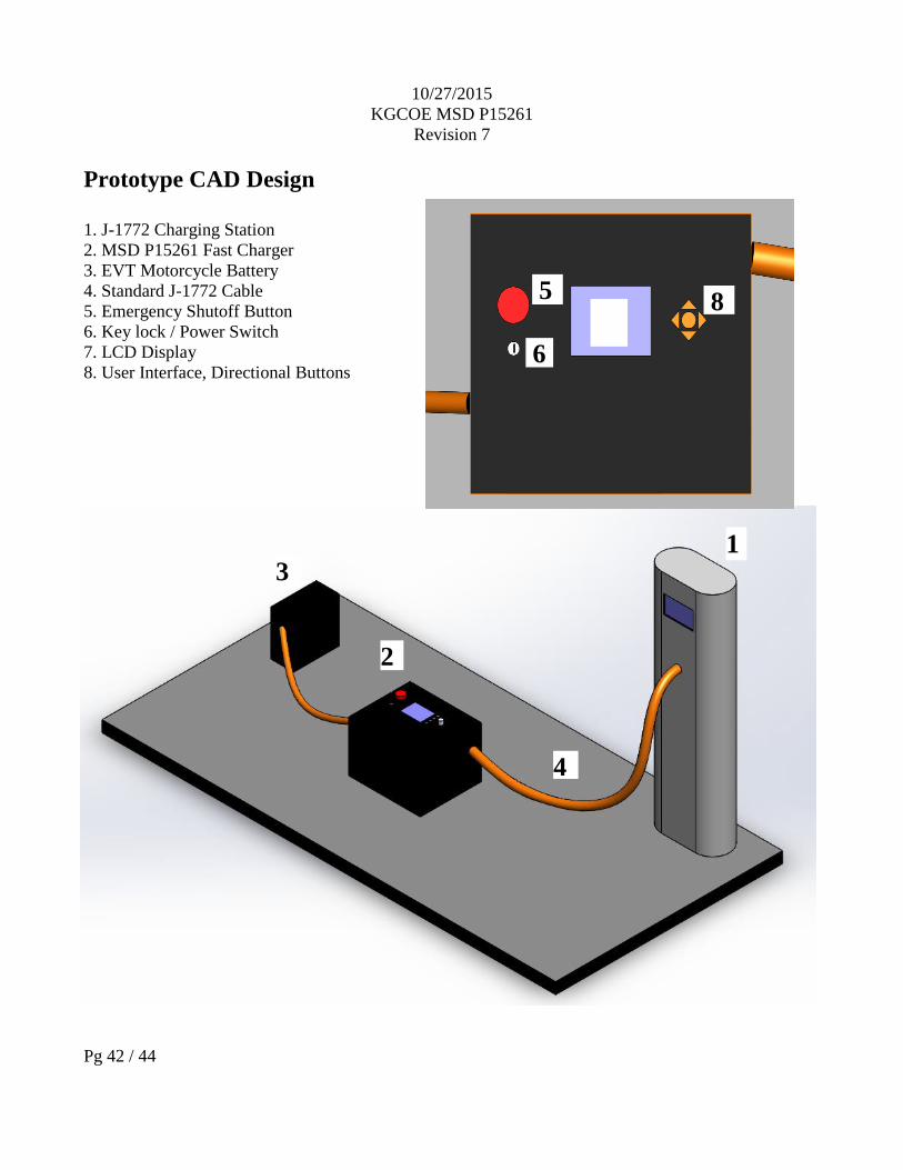
Prototype CAD Design
1. J-1772 Charging Station
2. MSD P15261 Fast Charger
3. EVT Motorcycle Battery
4. Standard J-1772 Cable
5. Emergency Shutoff Button
6. Key lock / Power Switch
7. LCD Display
8. User Interface, Directional Buttons
1
3
2
4
5
6
7 8

10/27/2015
KGCOE MSD P15261
Revision 7
Pg 43 / 44
Subsystem Bill of Materials (BoM)
Component Size Model Cost/unit Total Site
AC-DC system
Mosfet/IGBT 600 V, 50 A NGTB50N60FWG $2.38 $4.76 http://goo.gl/l954ba
Diode 600 V, 50 A 512-RHRG5060_F085 $3.91 $46.92 http://goo.gl/Ovu3dB
Capacitor (for Vripple) 10000 uF DCMC103T200CJ2D $35.35 $141.40 https://goo.gl/tCaeKr
Gate Driver 50kHz-100kHz PA0185NLT $3.00 $3.00 http://goo.gl/n5N8oJ
DC-DC System
Power MOSFET 300V, 88A,
40mOhm IXTH 88N30P $9.53 $133.42 http://goo.gl/Gmf9yS
Gate Driver 6-60V, 1.7A DRV8301 $2.5 $10 http://goo.gl/4y3z9p
DC Relay 600VAC, 90A CWU2490 $98.77 $98.77 http://goo.gl/VHBCIN
AC Relay 600VAC, 90A D2490 $85.19 $85.19 http://goo.gl/qzJ1gS
J1772 Connector N/A DSIEC2f-EV32S-NC $98 $98 http://goo.gl/TwhikR
Misc.
Parallax LCD 4x20 Characters 27979 $42.99 $42.99 http://goo.gl/y6iBUz
J-1772 Cable 10 Gauge wire 1033 $141 $141 https://goo.gl/V2T6WR
Buttons SPST contact
Buttons 30-101 $4.76 $23.8 http://goo.gl/yjwV8C
J-1772 Plug Female plug 1034 $65 $65 https://goo.gl/chHm7c
Fans 12V DC Fan FAD1-04010CSMW11 $2.5 $5 http://goo.gl/FkjAUg
PWM Driver 16 Channel, 12 bit PCA9685PW,112 $2.35 $2.35 http://goo.gl/vXZNGV
E-Stop Button SPST E Stop A165E-02 $20.87 $20.87 http://goo.gl/MZBR0a
Key Switch Key Switch Y101132C203NQ $11.73 $11.73 http://goo.gl/tQVCYk
High-Efficiency PWM
Power Driver 14.4 V/V, +/- 3 A
input DRV594 $28.22 $28.22 http://goo.gl/xIbCtt
Acrylic Sheet 18 in. X 24 in. 1AG2123A $21.37 $21.37 http://goo.gl/YPVJpR
Battery Wire, Ultra
Flexible, 6 Gauge, Red 10 Feet 6948K91 $17.50 $35.00 http://goo.gl/TV165a
Battery Wire, Ultra
Flexible, 6 Gauge,
Black 10 Feet 6948K91 $17.50 $35.00 http://goo.gl/TV165a
Husky 37 in. Mobile Job
Box 50 Gallon 209261 $64.00 $64.00 http://goo.gl/gZCsmo
Total: $1117.79

10/27/2015
KGCOE MSD P15261
Revision 7
Pg 44 / 44
References
1. http://publications.lib.chalmers.se/records/fulltext/184817/184817.pdf
2. http://www.ixys.com/Documents/AppNotes/IXAN0001.pdf
3. https://www.energystar.gov/ia/products/downloads/Electric_Vehicle_Scoping_Report.pdf?0544-2a1e
4. http://www.microchip.com/wwwproducts/Devices.aspx?product=PIC18F46K22
5. https://eewiki.net/display/microcontroller/CAN+Example+-+ATmega32M1+-+STK600
6. http://www.vicorpower.com/documents/application_notes/an_ConstantCurrent.pdf