key-operated switch gma 41 / gma 44 sw - gfg-inc.com · introduction the key-operated switch gma...
TRANSCRIPT

Key-Operated Switch
GMA 41 /
GMA 44 SW Operation Manual

3
Table of contents
Page Introduction ............................................................................................................................................. 4 Key function ............................................................................................................................................. 4 Distinction of GMA 41/44 SW models ..................................................................................................... 4 Relays......................................................................................................................................................... 5 P.C. boards of GMA 41/44 SW .................................................................................................................. 7 Terminal Diagram GMA 41/44 SW............................................................................................................ 8 Trouble shooting ..................................................................................................................................... 9 Technical data .......................................................................................................................................... 9

Introduction The key-operated switch GMA 41/44 SW serves as collective alarm for gas monitors, which consists of any quantity of GMA 41 B, GMA 41 ECB, GMA 44 B, or GMA 44 ECB. The gas monitors and the key-operated switch have to be connected by means of the bus system. Plug the key in to activate the key-operated switch. Now any new alarm to connected alarm devices or signal lines is suppressed. This may be useful for service and maintenance. Key function The key-operated switch provides 5 voltage-free relay contacts. These relays can be used to control external buzzers, lamps, or telephone lines in case of alarm or system fault. When the key is plugged in, the alarm-stop relay is activated and the stop LED flashes. In the standard configuration (non-deleting alarms), already reported alarms remain valid. New alarm signals, however, will be suppressed and the alarm relays (relays 1, 2, and 3) will not be activated in case of a new alarm. The GMA will not give a warning. This is particularly important during service and maintenance, e.g. when the sensitivity calibration of the connected transmitters is to be checked. The alternative configuration (deleting alarms) allows to de-activate even an already reported alarm.
Alarm-stop LED
Key lock
Pin connector bus system
LEDs (red) for alarm 1, 2, and 3
LED (green) for
operation
LED (yellow) for fault
Distinction of GMA 41/44 SW models
Key-operated switch Model Alarms Built-in 230V mains unit
Supply voltage
Suitable for GMA 41 and 44 models
GMA 41/44 SW 24V Standard Non-deleting No 24V DC 41 B 44 B
GMA 41/44 SW 24V Alternative Deleting No 24V DC 41 B 44 B
GMA 41/44 SW 230V Standard Non-deleting Yes 230V AC 41 ECB 44 ECB
GMA 41/44 SW 230V Alternative Deleting Yes 230V AC 41 ECB 44 ECB
The voltage supply of the key-operated switch GMA 41/44 SW 24V is specially designed for the operation with several GMA 41 ECB and 44 ECB.
4

Relays The key-operated switch GMA 41/44 SW provides 5 relays:
3 alarm relays for controlling external alarm devices 1 fault relay for failure report 1 alarm-stop relay as a signal, that the key-operated switch is activated and new alarms
are suppressed Alarm report - alarm 1, alarm 2, and alarm 3 • The relays are activated, if the relevant alarm threshold at one of the connected gas
monitors is exceeded. • Alarm reset is done at the relevant gas monitor. • The red LED "ALARM" is lit, if the alarm relay is activated. • For the switching behavior of the alarm relays after plugging the electronic key in please
refer to the scheme below. Fault • The relay is activated, if the key-operated switch is faulty. • The relay is activated, if one of the connected gas monitors is faulty. Alarm-stop • The relay is activated, if the key is plugged in. • Depending on the configuration, already existing alarms will be reset or remain valid. New
alarm signals will be suppressed. • The LED "STOP" flashes, when the alarm-stop relay is activated. The "ALARM-STOP" relay can be used e.g. to activate a warning panel reading "system out of order". The switching behavior of the relays is the same as for alarm or fault signals. Every relay can be operated as NC or NO contact in closed or open circuit systems. For the switching functions as NC and NO relays you will find contact clamps. The relay operation as closed or open circuit is set by means of the gravity hook on the LED board (see “p.c. boards of GMA 41/44SW”). The alarm relays and the alarm stop relay are operated as open circuit system, the fault relay is a closed circuit.
In the standard setting and without the key being plugged in, the switching functions of the relays are as follows:
The relay switches:
During gas alarm After gas alarm Relay for:
In detection mode (no gas) Not reset Reset Not reset Reset
In case of mains failure
In case of failure
In case of gas alarm and failure
Alarm 1 Ö
S Ö
S Ö
S
Ö S
Ö S
Ö S
Ö S
ÖS
Alarm 2 Ö
S Ö
S Ö
S
ÖS
Ö S
Ö S
Ö S
ÖS
Alarm 3 Ö
S Ö
S Ö
S
ÖS
Ö S
Ö S
Ö S
ÖS
Alarm-stop Ö
S Ö
S Ö
S
Ö S
Ö S
Ö S
Ö S
Ö S
Fault Ö
S Ö
S Ö
S
ÖS
ÖS
Ö S
Ö S
Ö S
5
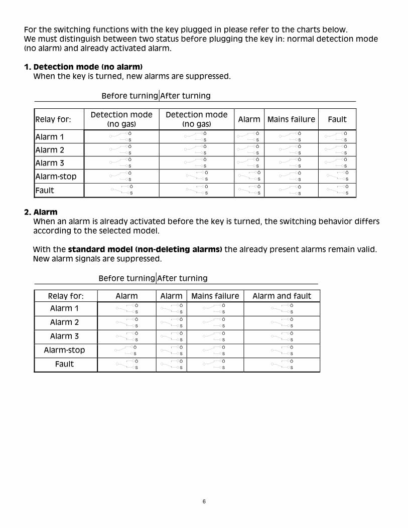
For the switching functions with the key plugged in please refer to the charts below. We must distinguish between two status before plugging the key in: normal detection mode (no alarm) and already activated alarm. 1. Detection mode (no alarm)
When the key is turned, new alarms are suppressed.
Before turning After turning
Relay for: Detection mode (no gas)
Detection mode (no gas)
Alarm Mains failure Fault
Alarm 1 Ö
S Ö
S Ö
S Ö
S Ö
S Alarm 2
Ö S
Ö S
Ö S
Ö S
Ö S
Alarm 3 Ö
S Ö
S Ö
S Ö
S Ö
S Alarm-stop
Ö S
ÖS
ÖS
Ö S
ÖS
Fault Ö
S Ö
S Ö
S Ö
S Ö
S 2. Alarm
When an alarm is already activated before the key is turned, the switching behavior differs according to the selected model.
With the standard model (non-deleting alarms) the already present alarms remain valid. New alarm signals are suppressed.
Before turning After turning
Relay for: Alarm Alarm Mains failure Alarm and fault
Alarm 1 Ö
S Ö
S Ö
S Ö
S Alarm 2
Ö S
ÖS
Ö S
Ö S
Alarm 3 Ö
S Ö
S Ö
S Ö
S Alarm-stop
Ö S
ÖS
Ö S
Ö S
Fault Ö
S Ö
S Ö
S Ö
S
6
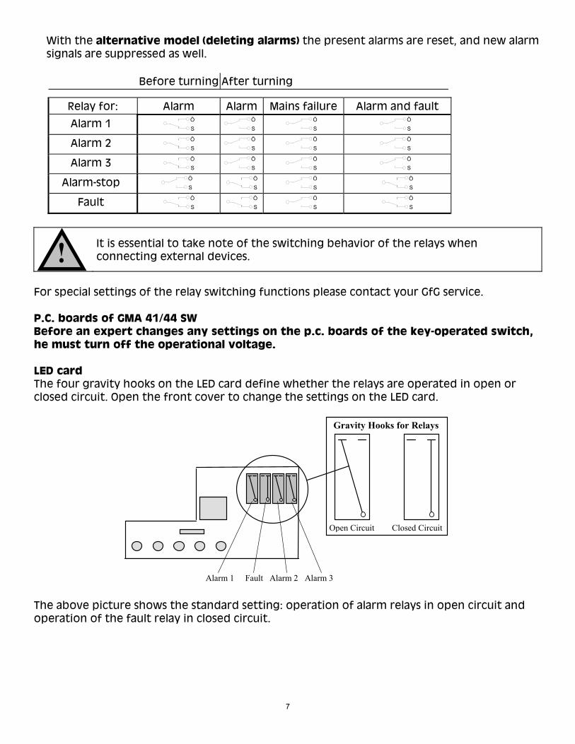
With the alternative model (deleting alarms) the present alarms are reset, and new alarm signals are suppressed as well.
Before turning After turning
Relay for: Alarm Alarm Mains failure Alarm and fault
Alarm 1 Ö
S Ö
S Ö
S Ö
S Alarm 2
Ö S
Ö S
Ö S
Ö S
Alarm 3 Ö
S Ö
S Ö
S Ö
S Alarm-stop
Ö S
ÖS
Ö S
Ö S
Fault Ö
S Ö
S Ö
S Ö
S
!
It is essential to take note of the switching behavior of the relays when connecting external devices.
For special settings of the relay switching functions please contact your GfG service. P.C. boards of GMA 41/44 SW Before an expert changes any settings on the p.c. boards of the key-operated switch, he must turn off the operational voltage. LED card The four gravity hooks on the LED card define whether the relays are operated in open or closed circuit. Open the front cover to change the settings on the LED card.
Gravity Hooks for Relays
Open Circuit Closed Circuit
Alarm 1 Fault Alarm 2 Alarm 3 The above picture shows the standard setting: operation of alarm relays in open circuit and operation of the fault relay in closed circuit.
7
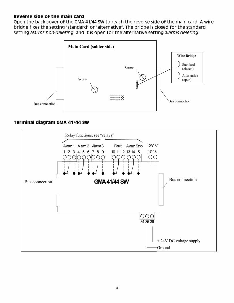
Reverse side of the main card Open the back cover of the GMA 41/44 SW to reach the reverse side of the main card. A wire bridge fixes the setting “standard“ or “alternative“. The bridge is closed for the standard setting alarms non-deleting, and it is open for the alternative setting alarms deleting.
Wire Bridge
Alternative(open)
Standard (closed)
Main Card (solder side)
Screw
Screw
Bus connection Bus connection
Terminal diagram GMA 41/44 SW
Relais - Funktionen, siehe Seiten 3 und 4Relay functions, see “relays”
1 2 3 4 5 6 7 8 9 17 18Alarm 1 Alarm 2 Alarm 3
10 11 12Fault 230 V
34 35 36
+24VMasse
GMA 41/44 SWBusverbindung
Ground+ 24V
13 14 15Alarm Stop
Bus connection
8
DC Spannungsversorgung
BusverbindungBus connection
DC voltage supply

9
Trouble shooting
Failure Cause Solution
No LEDs lit Operational voltage interrupted Connect operational voltage or check battery back-up
Technical data GMA 41/44 SW
Type: Key-operated switch for snap-on mounting to DIN rail Dimensions: 106 x 90 x 58 mm (WxHxD)
Current supply Operational voltage: GMA 41/44 SW 24V 24V DC
GMA 41/44 SW 230V 230V / 50Hz or 115V / 60 Hz or 24V DC Current consumption: Maximum 100 mA at 24 V DC
Maximum 2.6 W at 230V and 115 V
Primary fuse: Secondary fuse:
GMA 41/44 SW 230V T 0.08 A GMA 41/44 SW 230V T 0.50 A GMA 41/44 SW 24V T 0.50 A
Climate conditions for operation: -10 to +55 °C, 0 to 99 % r.h., 700 to 1,300 hPa
Recommended storage conditions for GMA 41/44
SW, spares:
0 to 30 °C, 20 to 80 % r.h.
Output Relays: Maximum switch voltage 250V AC 50/60 Hz or 250V DC
Maximum switch current 4 A AC/DC Maximum switch performance 1,000 VA AC or depending on
voltage 50 .. 200 W DC Relay outputs and mains connection are operation insulated
DIN Rail snap-on mounting:
DIN EN 50022
Safety Protection: DIN 40050 - IP -20
Protective separation: By means of safety transformer
GMA 41/44 SW 230V Type: BV EI 306 2064 2.6VA PRI 230V / SEC 18 V 50 - 60Hz
Protective insulation: As per EN 61010 up to over voltage category III and soiling degree 2


1194 Oak Valley Drive, Suite 20 Ann Arbor, Michigan 48108 United States of America
Phone: (800) 959-0329 or (734) 769-0573 Fax (734) 769-1888
E-mail: [email protected]: www.gfg-inc.com
GfG reserves the right of modification. 606 7004-044