key bifurcations of bursting polyrhythms in 3-cell … · key bifurcations of bursting polyrhythms...
TRANSCRIPT

Key Bifurcations of Bursting Polyrhythms in 3-CellCentral Pattern GeneratorsJeremy Wojcik1, Justus Schwabedal2, Robert Clewley2,3, Andrey L. Shilnikov2,3,4*
1 Applied Technology Associates, Albuquerque, New Mexico, United States of America, 2 Neuroscience Institute, Georgia State University, Atlanta, Georgia, United States
of America, 3 Department of Mathematics and Statistics, Georgia State University, Atlanta, Georgia, United States of America, 4 Department of Computational
Mathematics and Cybernetics, Lobachevsky State University of Nizhni Novgorod, Nizhni Novgorod, Russia
Abstract
We identify and describe the key qualitative rhythmic states in various 3-cell network motifs of a multifunctional centralpattern generator (CPG). Such CPGs are neural microcircuits of cells whose synergetic interactions produce multiple stateswith distinct phase-locked patterns of bursting activity. To study biologically plausible CPG models, we develop a suite ofcomputational tools that reduce the problem of stability and existence of rhythmic patterns in networks to the bifurcationanalysis of fixed points and invariant curves of a Poincare return maps for phase lags between cells. We explore differentfunctional possibilities for motifs involving symmetry breaking and heterogeneity. This is achieved by varying couplingproperties of the synapses between the cells and studying the qualitative changes in the structure of the correspondingreturn maps. Our findings provide a systematic basis for understanding plausible biophysical mechanisms for the regulationof rhythmic patterns generated by various CPGs in the context of motor control such as gait-switching in locomotion. Ouranalysis does not require knowledge of the equations modeling the system and provides a powerful qualitative approach tostudying detailed models of rhythmic behavior. Thus, our approach is applicable to a wide range of biological phenomenabeyond motor control.
Citation: Wojcik J, Schwabedal J, Clewley R, Shilnikov AL (2014) Key Bifurcations of Bursting Polyrhythms in 3-Cell Central Pattern Generators. PLoS ONE 9(4):e92918. doi:10.1371/journal.pone.0092918
Editor: Vladimir Brezina, Mount Sinai School of Medicine, United States of America
Received January 4, 2014; Accepted February 27, 2014; Published April 16, 2014
Copyright: � 2014 Wojcik et al. This is an open-access article distributed under the terms of the Creative Commons Attribution License, which permitsunrestricted use, distribution, and reproduction in any medium, provided the original author and source are credited.
Funding: JS was supported by the DFG (SCHW 1685/1-1). The Ph.D. studies of JW were funded by National Science Foundation (NSF) grant DMS-1009591. ASwas in part supported by NSF grant DMS-1009591, MESRF project 14.740.11.0919, RFFI 11-01-00001 as well as the GSU Brains and Behavior Program. The fundershad no role in study design, data collection and analysis, decision to publish, or preparation of the manuscript.
Competing Interests: Jeremy Wojcik is employed by Applied Technology Associates. There are no patents, products in development or marketed products todeclare. This does not alter the authors’ adherence to all the PLOS ONE policies on sharing data and materials, as detailed online in the guide for authors.
* E-mail: [email protected]
Introduction
A central pattern generator (CPG) is a circuit of neuronal cells
whose synergetic interactions can autonomously produce rhythmic
patterns of activity that determine vital motor behaviors in animals
[1–3]. CPGs have been found in many animals, where they have
been implicated in the control of diverse behaviors such as
heartbeat, sleep, respiration, chewing, and locomotion on land and
in water [4–7]. Mathematical modeling studies, at both abstract
and realistic levels of description, have provided useful insights into
the operational principles of CPGs [8–14]. Although many
dynamic models of specific CPGs have been developed, it remains
unclear how CPGs achieve the level of robustness and stability
observed in nature [15–22].
A common component of many identified CPGs is a half-center
oscillator (HCO), which is composed of two bilaterally symmetric
neurons reciprocally inhibiting each other to produce an
alternating anti-phase bursting pattern [23]. There has been
much work on the mechanisms giving rise to anti-phase bursting in
relaxation HCO networks, including synaptic release, escape and
post-inhibitory rebound [24,25]. Studies of HCOs composed of
Hodgkin-Huxley type model cells have also demonstrated the
possibility of bistability and the coexistence of several in-phase and
anti-phase bursting patterns based on synaptic time scales or
delays [26–28].
We are interested in exploring the constituent building blocks
— or ‘‘motifs’’ — that may make up more complex CPG circuits,
and the dynamic principles behind stable patterns of bursting that
may co-exist in the circuit’s repertoire of available states
[13,20,29]. We will refer to such multi-stable rhythmic patterns as
‘‘polyrhythms.’’ We consider the range of basic motifs comprising
three biophysical neurons and their chemical synapses, and how
those relate to, and can be understood from the known principles
of two-cell HCOs. We will study the roles of asymmetric and
unique connections, and the intrinsic properties of their associated
neurons, in generating a set of coexisting synchronous patterns of
bursting waveforms. The particular kinds of network structure that
we study here reflect the known physiology of various CPG
networks in real animals. Many anatomically and physiologically
diverse CPG circuits involve a three-cell motif [30,31], including
the spiny lobster pyloric network [1,32], the Tritonia swim circuit,
and the Lymnaea respiratory CPGs [33–36].
An important open question in the experimental study of real
CPGs is whether they use dedicated circuitry for each output
pattern, or whether the same circuitry is multi-functional [37,38],
i.e. can govern several behaviors. Switching between multi-stable
rhythms can be attributed to input-dependent switching between
attractors of the CPG, where each attractor is associated with a
specific rhythm. Our goal is to characterize how observed multi-
stable states arise from the coupling, and also to suggest how real
PLOS ONE | www.plosone.org 1 April 2014 | Volume 9 | Issue 4 | e92918
circuits may take advantage of the multi-stable states to
dynamically switch between rhythmic outputs. For example, we
will show how motif rhythms are selected by changing the relative
timing of bursts by physiologically plausible perturbations. We will
also demonstrate how the set of possible rhythmic outcomes can be
controlled by varying the duty cycle of bursts, and by varying the
network coupling both symmetrically and asymmetrically [17,20].
We also consider the role of a small number of excitatory or
electrical connections in an otherwise inhibitory network. Our
greater goal is to gain insight into the rules governing pattern
formation in complex networks of neurons, for which we believe
one should first investigate the rules underlying the emergence of
cooperative rhythms in smaller network motifs.
In this work, we apply a novel computational tool that reduces
the problem of stability and existence of bursting rhythms in large
networks to the bifurcation analysis of fixed points (abbreviated
FPs) and invariant circles of Poincare return maps. These maps are
based on the analysis of phase lags between the burst initiations in
the cells. The structure of the phase space of the map reflects the
characteristics the state space of the corresponding CPG motif.
Equipped with the maps, we are able to predict and identify the set
of robust bursting outcomes of the CPG. These states are either
phase-locked or periodically varying lags corresponding to FP or
invariant circle attractors (respectively) of the map. Comprehen-
sive simulations of the transient phasic relationships in the network
are based on the delayed release of cells from a suppressed,
hyperpolarized state. This complements the phase resetting
technique and allows a thorough exploration of network oscilla-
tions with spiking cells [39]. We demonstrate that synaptically-
coupled networks possess stable bursting patterns that do not occur
in similar motifs with gap junction coupling, which is bidirection-
ally symmetric [40].
Results
Our results are organized as follows: first, we describe our new
computational tools, which are based on 2D return maps for phase
lags between oscillators. This is a non-standard method that has
general utility outside of our application, and we therefore present
it here as a scientific result. We then present maps for symmetric
inhibitory motifs and examine how the structure of the maps
depends on the duty cycle of bursting, i.e. on how close the
individual neurons are to the boundaries between activity types
(hyperpolarized quiescence and tonic spiking). Here, we also
examine bifurcations that the map undergoes as the rotational
symmetry of the reciprocally coupled 3-cell motif is broken. This is
followed by a detailed analysis of bifurcations of fixed point (FP)
and invariant circle attractors of the maps, which we show for
several characteristic configurations of asymmetric motifs, includ-
ing a CPG based on a model of the pyloric circuit of a crustacean.
We conclude the inhibitory cases with the consideration of the fine
structure of a map near a synchronous state. We then discuss the
maps for 3-cell motifs with only excitatory synapses, which is
followed by the examination of mixed inhibitory-excitatory motifs,
and finally an inhibitory motif with an additional electrical synapse
in the form of a gap junction.
A computational method for phase lag return mappingsWe first introduce the types of trajectories we focus on and how
we measure them. The reduced leech heart interneuron can
demonstrate many regular and irregular activity types, including
hyper- and de-polarized quiescence, tonic spiking and bursting
oscillations. We focus on periodic bursting, and Figure 1 shows a
trajectory (dark gray) in the 3D phase space of the model. The
helical coils of the trajectory correspond to the active tonic spiking
period of bursting due to the fast sodium current. The flat section
corresponds to the hyperpolarized quiescent portion of bursting
due to the slow recovery of the potassium current. In Fig. 1, two
snapshots (at t~0 and t~10 s) depict the positions of the blue,
green and red spheres representing the momentarily states of all
three interneurons. The coupling between the cells is chosen weak
so that network interactions should only affect the relative phases
of the cells on the intact bursting trajectory, i.e. without deforming
the trajectory.
V shiftK2 is a model parameter that measures the deviation from
the half-activation voltage V1=2~{0:018 V of the potassium
channel, m?K2~1=2. We use V shift
K2 as a bifurcation parameter to
control the duty cycle (DC) of the interneurons. The duty cycle is
the fraction of the burst period in which the cell is spiking, and is a
property known to affect the synchronization properties of coupled
bursters [16,17]. The individual cell remains bursting within the
interval V shiftK2 [½{0:024235,{0:01862�. At smaller values of
V shiftK2 , it begins oscillating tonically about the depolarized steady
state, and becomes quiescent at greater values of V shiftK2 . Therefore,
the closer the cell is to either boundary, the DC of bursting
becomes longer or shorter respective: the DC is about 80% at
V shiftK2 ~{0:0225 V and 25% at V shift
K2 ~{0:01895 V. For 50%
DC we set V shiftK2 ~{0:021 V, in the middle of the bursting
interval (see Fig. 2).
When an isolated bursting cell is set close to a transition to
either tonic spiking or hyperpolarized quiescence, its network
dynamics become sensitive to external perturbations from its pre-
synaptic cells. For example, when the post-synaptic cell is close to
the tonic-spiking boundary, excitation can cause the post-synaptic
cell to burst longer or even move it (temporarily) over the
boundary into the tonic spiking (TS) region. In contrast, inhibition
shortens the duty cycle of the post-synaptic neuron if it does not
completely suppress its activity (Fig. 3).
The return map for phase lags. We reduce the problem of
the existence and stability of bursting rhythmic patterns to the
bifurcation analysis of fixed points (FPs) and invariant curves of
Poincare return maps for phase lags between the neurons. In this
study, we mostly consider relatively weakly coupled motifs, but our
approach has no inherent limitation to weak coupling. Here, the
weakly coupled case is a pilot study that lets us test our technique
and also uncover all rhythms, both stable and unstable, that can
possibly occur in the network. Detailed scrutiny of the return maps
is computationally expensive: an exploration of one parameter set
can take up to three hours on a state-of-the-art desktop
workstation depending on the accuracy of the mesh of initial
conditions and length of the transients computed.
The phase relationships between the coupled cells are defined
through specific events, t(n)1 ,t(n)
2 ,t(n)3
n o, when their voltages cross a
threshold, Hth, from below. Such an event indicates the initiation
of the nth burst in the cells, see Fig. 4. We choose Hth~{0:04 V,
above the hyperpolarized voltage and below the spike oscillations
within bursts.
We define a sequence of phase lags by the delays in burst
initiations relative to that of the reference cell 1, normalized over
the current network period or the burst recurrent times for the
reference cell, as follows:
Key Bifurcations of Bursting Polyrhythms in CPGs
PLOS ONE | www.plosone.org 2 April 2014 | Volume 9 | Issue 4 | e92918

Dw(n)21 ~
t(nz1)21 {t
(n)21
t(nz1)1 {t
(n)1
and Dw(n)31 ~
t(nz1)31 {t
(n)31
t(nz1)1 {t
(n)1
, mod 1: ð1Þ
An ordered pair, Mn~ Dw(n)21 ,Dw(n)
31
� �, defines a forward iterate,
or a phase point, of the Poincare return map for the phase lags:
P : Mn?Mnz1 ð2Þ
A sequence, (Dw(n)21 ,Dw
(n)31 )
n oN
n~0, yields a forward phase lag trajectory,
Mnf gNn~0, of the Poincare return map on a 2D torus ½0,1)|½0,1)
with phases defined on mod 1 (Fig. 5). Typically, such a trajectory
is run for N~90 bursting cycles in our simulations. The run can
be stopped when the distance between several successive iterates
becomes less than some preset value, say DDMn{MnzkDDv10{3
and k~5. This is taken to mean that the trajectory has converged
to a fixed point, M�, of the map. This FP corresponds to a phase
locked rhythm and its coordinates correspond to specific constant
phase lags between the cells. By varying the initial delays between
cells 2 and 3 with respect to the reference cell 1, we can detect any
and all FPs of the map and identify the corresponding attractor
basins and their boundaries.
We say that coupling is weak between two cells of a motif when
the convergence rate to any stable FP of the return map is slow.
This means that the distance between any two successive iterates
of a trajectory of the return map remains smaller than some
Figure 1. Network motif diagram and phase space of typical bursting trajectory of single cell. (A) Caricature of a mixed 3-cell motif withinhibitory and excitatory synapses, represented by . and .-like, resp., as well as an electrical connection through the gap junction betweeninterneurons 1 and 2. (B) Bursting trajectory (gray) in the 3D phase space of the model, which is made of the ‘‘active’’ spiking (solenoid-like shaped)
and the flat hyperpolarized sections. The gap between the 2D slow nullcline, m0
K2~0, and the low knee on the slow quiescent manifold, Meq,determines the amount of inhibition needed by the active pre-synaptic cell above the synaptic threshold, Hsyn, to either slow or hold the post-synaptic cell(s) at a hyperpolarized level around {0:06 V. The positions of the red, green and blue spheres on the bursting trajectory depict thephases of the weakly-connected cells of the CPG at two instances: the active red cell inhibits, in anti-phase, the temporarily inactive green and bluecells at two time instances.doi:10.1371/journal.pone.0092918.g001
Figure 2. Schematic showing regimes and how burst durationchanges as the bifurcation parameter, V shift
K2 is varied. Burst
duration increases as V shiftK2 approaches the boundary of the tonic
spiking (TS) state, and decreases towards the boundary of hyperpolar-ized quiescence (Q). The post-synaptic cell on the network cantemporarily cross either boundary when excited or inhibited bysynaptic currents from pre-synaptic neurons.doi:10.1371/journal.pone.0092918.g002
Key Bifurcations of Bursting Polyrhythms in CPGs
PLOS ONE | www.plosone.org 3 April 2014 | Volume 9 | Issue 4 | e92918

bound, e.g. max DDMn{Mnz1DDv0:05. Therefore, we can say that
coupling is relatively strong if a remote transient reaches a FP of
the map after just a few iterates. We point out that the
convergence can be quick even for nominally small gsyn provided
that an individual cell is sufficiently close to either boundary of
bursting activity (tonic spiking or quiescence).
We now make some technical remarks concerning computa-
tional derivations of the map, P. A priori, the initial period
(recurrence time) of the motif’s dynamics is unknown due to the
unknown outcome of nonlinear cell interactions; furthermore, it
varies over the course of the bursting transient until it converges to
a fixed value on the phase locked state. Thus, we control the initial
phases between the reference cell and the others releasing the
latter from inhibition at various delays. To do this, we first
estimate the initial phase lag with a first order approximation,
Dw(0)21 ,Dw(0)
31
� �between the networked neurons, as the phase lags
Dw?21,Dw?31
� �on the periodic synchronous solution of period
Tsynch. Note that Dw?21 is shifted away from Dw?31, i.e. is advanced
or delayed. Notice that, in the weakly coupled case, the recurrent
times of the reference cell are close to Tsynch, which implies
(Dw?21,Dw?31)&(Dw(0)21 ,Dw
(0)31 ). By setting Dw21~Dw31~0 and t1j~0
at V1~Hth we can parameterize the synchronous solution by a
time shift, 0ƒt1jvTsynch
� �or, alternatively, by phase lags
Figure 3. Variations of bursting of the post-synaptic cell with synaptic strength. Step-wise increases in excitatory (top) and inhibitory(bottom) strengths, gsyn, from pre-synaptic cell(s). Increase of the duty cycle (DC) of bursting is through the extension of either the active phases ofbursting or the interburst intervals as the post-synaptic cell on the network is shifted by synaptic perturbations toward either the tonic spiking (TS) orhyperpolarized quiescence (Q) boundaries in Fig. 2.doi:10.1371/journal.pone.0092918.g003
Figure 4. Sample voltage traces depicting phase measure-ments. The phase of the reference cell 1 (blue) is reset when V1
reaches an auxiliary threshold, Hth~{40 mV, at t(n)1 . The recurrent time
delays, t(n)21 and t
(n)31 between the burst onsets in cell 1 and cells 2 (green)
and 3 (red), normalized over the cycle period, t(nz1)1 {t
(n)1
h i, define a
sequence of phase lags: Dw(n)21 ,Dw
(n)31
n o.
doi:10.1371/journal.pone.0092918.g004
Key Bifurcations of Bursting Polyrhythms in CPGs
PLOS ONE | www.plosone.org 4 April 2014 | Volume 9 | Issue 4 | e92918

0ƒDwj1v1� �
. Thus, we can set the initial phase lags by releasing
the reference cell and keeping the others suppressed for durations
t12~Dw(0)21 Tsynch and t13~Dw(0)
31 Tsynch from the same initial point
on the synchronous bursting trajectory, given by
Vi~Hth~{0:04 V.
To complete a single phase lag map we choose the initial phase
lags to be uniformly distributed on a grid of at least 40|40 points
over the ½0,1)|½0,1) torus. The initial guess for the phase lag
distribution is based on knowledge of a trajectory for a
synchronized motif, whose period is already known. This guess
will therefore differ from the self-consistent phase lag distribution
once the networked cells begin to interact, especially with coupling
strength variations. Similarly, the estimated network period,
Tsynch, will differ from the network’s actual self-consistent period.
In computations, this may result in fast jumps from the set of
guessed initial phases from n~0 to n~1. These jumps are artifacts
of our setup and not relevant to our study of the attractors, and so
we begin recording the phase lag trajectory settled from the second
bursting cycle. Due to weak coupling, transients do not evolve
quickly, and we connect phase lag iterates of the map by straight
Figure 5. Poincare return maps depicted on the torus. The return maps for the phase lags fDw(n)21 ,Dw
(n)31 g between homogeneous cells at 50%
DC correspond to trajectories on a 2D torus ½0,1)|½0,1). Different colors denote attractor basins of several FPs corresponding to phase locked statesof distinct bursting rhythms.doi:10.1371/journal.pone.0092918.g005
Figure 6. A comparison of time evolutions of phase lags and their motion in the 2D space of phase differences. (A) Time evolutions ofthe phase lags, Dw31 (gray) and Dw21 (blue), exponentially converging to phase locked states after 50 burst cycles with short duty cycle,gsyn~5|10{4 . (B) The corresponding Poincare phase lag map revealing three stable FPs (shown in blue, red and green) at Dw21,Dw31ð Þ~ 1
2, 1
2
� �, 0, 1
2
� �,
12
,0� �
and two unstable FPs (dark dots) at 23
, 13
� �and 1
3, 2
3
� �. The attractor basins of the three stable FPs are color coded by the color of the FP, and are
separated by the separatrices of six saddle FPs (smaller dots). Arrows on representative lines that connect iterates indicate the forward direction ofiterates. See note at the end of Methods regarding interpretation of the lines and colors.doi:10.1371/journal.pone.0092918.g006
Key Bifurcations of Bursting Polyrhythms in CPGs
PLOS ONE | www.plosone.org 5 April 2014 | Volume 9 | Issue 4 | e92918

lines in order to demonstrate and preserve the forward order,
making them superficially resemble continuous-time vector fields
in a plane. Lastly, we unfold the torus onto a unit square for the
sake of visibility.
Note on interpreting phase lag diagrams. We use a
consistent labeling convention to make our diagrams of the phase
lag maps easy to interpret. In the first presentation of such a map
(Fig. 6 in the next section), we annotate the diagram with arrows to
Figure 7. Time evolutions of voltage traces in the short duty cycle motif showing switching between coexisting rhythms. Threecoexisting stable rhythms: 1\f2E3gð Þ (first episode), 3\f1E2gð Þ (second episode) and 2\f1E3gð Þ (third episode) in the short duty cycle motif with25% DC with +5% random perturbations applied to all inhibitory connections with gsyn~0:0005. Switching between rhythms is achieved by theapplication of appropriately-timed hyperpolarized pulses that release the targeted cells.doi:10.1371/journal.pone.0092918.g007
Figure 8. Phase lag maps in the long duty cycle motif and switching between two coexisting rhythms. (A) Symmetric phase lag map for80% DC, which possesses two stable FPs Dw21,Dw31ð Þ~ 2
3, 1
3
� �and 1
3, 2
3
� �of equal basins that correspond to a counter-clockwise 1[3[2ð Þ and
clockwise 1[2[3ð Þ traveling waves. The other three FPs have rather narrow basins, thus the traveling waves dominate the behavioral repertoire ofthe network. (B) Map corresponding to the clockwise biased motif with ~0:1 reveals the asymmetric basins of the robust rhythms after threesaddles have moved closer to the stable FP at 1
3, 2
3
� �. (C) Bistability: switching from the counter-clockwise, 1[3[2ð Þ, to the clockwise, 1[2[3ð Þ,
traveling wave in this motif, after releasing the target blue cell from hyperpolarized silence due to an external inhibitory pulse.doi:10.1371/journal.pone.0092918.g008
Key Bifurcations of Bursting Polyrhythms in CPGs
PLOS ONE | www.plosone.org 6 April 2014 | Volume 9 | Issue 4 | e92918

show the directions of the map on successive forward iterates. We
also label the position of FPs with colored dots. Larger dots are
used for the stable FPs than the saddle points. The colors of the
stable FPs (red, green, and blue) correspond to the colors of the
computed phase lag trajectories that approach them (thereby
depicting the basins of attraction). In Fig. 6, we indicate the
directions of forward iterates of that map to assist the reader in
their interpretation. However, all subsequent figures depict
dynamics with these same essential interpretable features: all
colored trajectories flow towards their color-coordinated FP, and
small dots indicate saddle points. We also note that the origin in
our maps has a complex fine structure but acts globally as a
repeller. As such, we do not depict those FPs explicitly in the full-
scale phase lag diagrams. A later section explicitly examines the
fine structure near the origin.
Multistability and duty cycle in homogenous inhibitorymotifs
We first examine three homogeneous (permutationally symmet-
ric) configurations of the network with nearly identical cells and
connections. We demonstrate that these symmetric network motifs
are multistable and hence able to produce several coexisting
bursting patterns. The homogeneous case allows us to reveal the
role of the duty cycle as an order parameter that determines what
robust patterns are observable. We suggest a biologically plausible
switching mechanism between the possible bursting patterns by
application of a small hyperpolarized current that temporarily
blocks a targeted cell.
Short duty cycle motif. We begin with a weakly coupled
with gsyn~5|10{4, homogeneous motif with 25% DC and
V shiftK2 ~{0:01895 V, which is close to the transition boundary
between bursting and hyperpolarized quiescence. Proximity to the
Figure 9. Time evolutions of voltage traces and phase lag map for the medium duty cycle motif. (A) Transients of the phase lags, Dw31
(gray) and Dw21 (blue), converging to several phase locked states after 90 burst cycles in the medium duty cycle motif. (B) The phase lag Poincare maprevealing five stable FPs: red dot at 0, 1
2
� �, green 1
2,0
� �, blue 1
2, 1
2
� �, black 2
3, 1
3
� �and purple 1
3, 2
3
� �, corresponding to the anti-phase 3\f1E2gð Þ,
2\f1E3gð Þ, 1\f2E3gð Þ bursts, and traveling clockwise 1[2[3ð Þ and counter-clockwise 1[3[2ð Þ waves; the attractor basins of the same colors aresubdivided by separatrices of six saddles (smaller brown dots).doi:10.1371/journal.pone.0092918.g009
Figure 10. Voltage traces showing the five bursting polyrhythms in the medium duty cycle motif. Here, we choose gsyn~5|10{3 toensure short transients for the purpose of illustration. Inhibitory pulses (horizontal bars) suppress then release the targeted cells, thus causingswitching between the co-existing rhythms: 1\f2E3gð Þ in episode (i), traveling waves 1[2[3ð Þ in (ii) and 1[3[2ð Þ in (iii), followed by 2\f1E3gð Þled by cell 2 in (iv). Having released cells 1 and 2 simultaneously, this makes cell 3 lead the motif in the 3\f1E2gð Þ rhythm in the fifth episode, (v).doi:10.1371/journal.pone.0092918.g010
Key Bifurcations of Bursting Polyrhythms in CPGs
PLOS ONE | www.plosone.org 7 April 2014 | Volume 9 | Issue 4 | e92918

boundary means that even weak inhibition is able to suppress a
postsynaptic cell that is near the hyperpolarized quiescent state
(Figs. 1 and 3).
Figure 5A shows the transient behaviors of the iterates of the
phase lags Dw(n)21 and Dw(n)
31 (shown in blue and gray colors) arising
from initial conditions distributed uniformly over the unit interval.
The phase lags exponentially converge to phase-locked states near
0 and 12.
Using Eq. (2), we compute the map P that is shown in Fig. 6B.
The projection of the map onto the unit square is an efficient way
to represent the synchronized evolution of the phase lags and
facilitates easy identification of phase-locked states. These states
are identified by three coexisting stable FPs or attractors of the
system to which all forward iterates converge. Here, the FPs are:
red at Dw21&0,Dw31&12
� �, green at 1
2,0
� �, and blue at 1
2, 1
2
� �. The
attractor basins of the stable FPs are shown in the corresponding
colors. The attractor basins are subdivided by separatrices
(incoming and outgoing sets) of six saddle FPs (shown by small
dots) in the map. See the end of Methods for details on
interpreting the diagram.
The robustness of a rhythm to perturbations is related to the size
of its attractor basin. Similarly, FPs that have much larger basins
than others can be thought of as ‘‘dominating’’ the phase plane in
terms of likelihood of becoming the active state for a random
initial condition or perturbation. Two triplets of saddles surround
two more unstable FPs located at approximately 23
, 13
� �and 1
3, 2
3
� �.
The immediate neighborhood of the origin has a complex
structure involving several FPs packed closely together, but
globally it acts as a repeller (see later section for a detailed analysis
of this).
Let us interpret the role of a stable FP, for example the red one,
in terms of phase-locked bursting patterns. Since the phases are
defined modulo one, the coordinates (Dw21,Dw31)~ 0, 12
� �, imply
that the corresponding rhythm is characterized by two fixed
conditions w1~w2 and w1{w3~12. In other words, the reference
cell fires in-phase with cell 2 and in anti-phase with cell 3.
Symbolically, we will use the following notation for this rhythm:
3\f1E2gð Þ, in which in-phase and anti-phase bursting are
represented by (Dw12~0, or E) and (Dw13~12
or \), respectively.
Following this notation, the stable FP (blue) at 12
, 12
� �corresponds to the robust 1\f2E3gð Þ pattern, while the stable
(green) FP 12
,0� �
corresponds to the 2\f1E3gð Þ pattern. These
coexisting bursting rhythms are shown in Fig. 7. The motif can be
made to switch between the polyrhythms by applying external
pulses of appropriate duration to the targeted cells.
Two FPs around Dw21,Dw31ð Þ~ 13
, 23
� �and 2
3, 1
3
� �correspond to
clockwise and counter-clockwise traveling waves (respectively) that
we denote 1[2[3ð Þ and 1[3[2ð Þ. Here, the period of either
traveling wave is broken into three episodes in which each cell is
actively bursting one at a time. For example, in Fig. 4 for the
clockwise bursting, 1[2[3ð Þ, the cell ordering is 1-2-3 before the
pattern repeats. The co-existence of these two waves originates
from the rotational symmetry of the homogeneous motif.
However, both such traveling bursting waves are not robust and
therefore cannot be observed in the motif with a short duty cycle
because the corresponding FPs are repelling, so that a small
perturbation will cause the phase lags of such a traveling rhythm to
transition to those corresponding to one of three ‘‘pacemaker’’
states, as shown in Fig. 7.
Long duty cycle motif. Next, we consider the bursting motif
that has a longer duty cycle of 80%, set by V shiftK2 ~{0:0225 V.
This brings the cells closer to the boundary separating bursting
and tonic spiking activities (Fig. 3). The corresponding return map
for the phase lags is shown in Fig. 8A. There are two equally
dominating stable FPs, Dw21,Dw31ð Þ& 23
, 13
� �and 1
3, 2
3
� �, corre-
Figure 11. Phase lag maps near a saddle-node bifurcation for an asymmetric motif. (A) Phase lag map for the short duty cycle motif andcoupling asymmetry ~0:41: the three saddles surrounding the stable FP (Dw21,Dw31)~ 2
3, 1
3
� �, are about to merge and vanish with other three
stable FPs through simultaneous saddle-node bifurcations; the FP at Dw21,Dw31ð Þ~ 13
, 23
� �remains unstable. (B) For w0:42 the FP
Dw21,Dw31ð Þ~ 23
, 13
� �becomes the only attractor of the map, which corresponds to the only robust 1[3[2ð Þ traveling wave. The network motif
is inset, where darker connections are stronger.doi:10.1371/journal.pone.0092918.g011
Key Bifurcations of Bursting Polyrhythms in CPGs
PLOS ONE | www.plosone.org 8 April 2014 | Volume 9 | Issue 4 | e92918

sponding to the now highly robust counter-clockwise 1[3[2ð Þand clockwise 1[2[3ð Þ traveling waves.
Figure 8B illustrates the waveforms, as well as the bistability of
the motif initially producing the counter-clockwise, 1[3[2ð Þ,traveling wave that reverses into the clockwise one, 1[2[3ð Þ,after a 10 second inhibitory pulse ended and released the blue
reference cell to initiate a burst.
Medium duty cycle motif. To complete the examination of
the influence of duty cycle on the repertoire and robustness of
bursting outcomes of the homogeneous motif, we now consider the
case of the medium-length duty cycle, 50%, set by
V shiftK2 ~{0:021 V (the middle interval shown in Fig. 3).
Similarly to Figure 5A, Figure 9A illustrates the evolution of
Dw21 and Dw31 (shown in blue and gray colors) from initial
conditions uniformly distributed over the unit interval. One can
Figure 12. Enlargement of the phase lag map for the short duty cycle motifs. (A) Case g~0:185 depicts a stable invariant circle near aheteroclinic connection between the surrounding saddles that produces a small-amplitude phase jitter in the voltage traces. (B) Case ~0:32
illustrates the change in stability for the FP at (Dw21,Dw31)~ 23
, 13
� �at large values of .
doi:10.1371/journal.pone.0092918.g012
Figure 13. Phase lag maps for the long duty cycle motif with single connection asymmetry. (A) The map for case gsyn21 ~1:5gsyn possesses
two attractors: one dominant at 13
, 23
� �, and another at 2
3, 1
3
� �with a smaller basin; note a saddle point in the proximity of the latter, which is a
precursor of a saddle-node bifurcation. (B) Case gsyn21 ~2gsyn, which has a single attractor corresponding to the clockwise 1[2[3ð Þ traveling wave.
doi:10.1371/journal.pone.0092918.g013
Key Bifurcations of Bursting Polyrhythms in CPGs
PLOS ONE | www.plosone.org 9 April 2014 | Volume 9 | Issue 4 | e92918

observe transients ultimately converging to multiple constant
phase locked states. The corresponding map P is presented in
Fig. 9B. In contrast to the case of short and long duty cycle motifs,
the map for the medium duty cycle motif with weak homogeneous
connections reveals the coexistence of five stable FPs: the red one
at 0, 12
� �, the green one at 1
2,0
� �, the blue one at 1
2, 1
2
� �, the black
one at 23
, 13
� �and the gray one at 1
3, 2
3
� �. These FPs represent,
correspondingly, five robust polyrhythms: the anti-phase
3\f1E2gð Þ, 2\f1E3gð Þ, 1\f2E3gð Þ bursting patterns, and two
traveling waves, clockwise, 1[2[3ð Þ, and counter-clockwise,
1[3[2ð Þ. By externally applying a current pulse to a targeted
cell we can deliberately switch between the co-existing bursting
patterns (Fig. 10).
Asymmetric inhibitory motifsIn this section, we elucidate how and what intrinsic properties of
the individual bursting cells affect the multistability of the 3-cell
inhibitory motif. The answer involves an interplay between the
competitive dynamical properties of individual neurons and the
cooperative properties of the network. More specifically, it relies
on how close an isolated cell is to the boundary between bursting
and hyperpolarized quiescence and how sensitive the post-synaptic
cell is to the (even weakly) inhibitory current generated by the pre-
Figure 14. Transformation stages of the phase lag maps for an asymmetric medium duty cycle motif. For the network motif shown(darker connections are stronger), a single connection g
syn31 increases from 1:04gsyn in (A), to 1:4gsyn in (B), to 1:6gsyn in (C). In (A), the saddle between
the FPs Dw21,Dw31ð Þ~ 0, 12
� �and 1
3, 2
3
� �moves closer to the latter, then annihilates through a saddle-node bifurcation. In doing so, the attractor basin
of the dominant red FP at 0, 12
� �widens after absorbing the basin of the vanished FP in (B). In (C) a second saddle-node bifurcation annihilates the red
FP. While the counter-clockwise and reciprocal connections between cell 2 and cells 1 and 3 remain intact, the other three stable FPs, blue at 12
, 12
� �,
green 12 ,0� �
and 23 , 1
3
� �, persist in the map.
doi:10.1371/journal.pone.0092918.g014
Key Bifurcations of Bursting Polyrhythms in CPGs
PLOS ONE | www.plosone.org 10 April 2014 | Volume 9 | Issue 4 | e92918

synaptic cells. We investigate these ideas by introducing asymme-
tries into the coupling of our homogeneous network motif. We
focus on several representative cases of asymmetrically coupled
motifs with one or more altered synaptic strengths, and we will
elaborate on their bifurcations as we vary the asymmetry.
From multistability to the 1[3[2ð Þ pattern. In this
subsection, we analyze bifurcations occurring en route from the
homogeneous 3-cell motif to a rotationally-symmetric one, during
which all clockwise- and counter-clockwise-directed synapses are
simultaneously increased and decreased, respectively. In the
limiting case of a clockwise, uni-directionally coupled motif there
is a single traveling wave. The question is: in what direction will
the wave travel?
We use a new bifurcation parameter, , which controls the
rotational symmetry as the deviation from the nominal coupling
strengths, gsyn~5|10{4, such that gsyn(1+ ) and 0ƒ ƒ1.
The limit ?1 corresponds to the unidirectional case. Recall
that initially, at ~0, both the traveling waves 1[2[3ð Þ and
1[3[2ð Þ are unstable in the short duty cycle motif with 20%DC. Then, the network can only generate the 1\f2E3gð Þ,2\f1E3gð Þ, 3\f1E2gð Þ pacemaker rhythms.
Figure 11A depicts P at a critical value of ~0:41, and
reveals that the FP (Dw21,Dw31)~ 23
, 13
� �is stable. Thus the
counter-clockwise traveling wave, 1[3[2ð Þ, is now observable
in the asymmetric motif. The value ~0:41 is a bifurcation value
because further increase make the three saddles and the three
Figure 15. Transformation stages of the phase lag maps for the pyloric circuit motif. Here, a single connection gsyn23 decreases from 0:9gsyn,
0:6 and 0:2gsyn through to 0 in (A)–(D), respectively. Going from (A) to (B), a triplet of saddle-node bifurcations eliminate first the clockwise 13
, 23
� �FP,
and then subsequently the green FP at 12
,0� �
in (B) to (C). The growing domain of the dominant blue FP at 12
, 12
� �widens further from (C) to (D) after
the stable counter-clockwise, 23
, 13
� �, FP is annihilated through the final saddle-node bifurcation.
doi:10.1371/journal.pone.0092918.g015
Key Bifurcations of Bursting Polyrhythms in CPGs
PLOS ONE | www.plosone.org 11 April 2014 | Volume 9 | Issue 4 | e92918

initially stable FPs (blue, green and red), merge in pairs and
annihilate though three simultaneous saddle-node bifurcations.
After that, the FP around 23
, 13
� �becomes the global attractor of the
network (see Fig. 11B) at ~0:42, which produces the single
counter-clockwise 1[3[2ð Þ traveling wave, while the FP at 13
, 23
� �remains unstable.
Next we have to characterize the missing stages for the
transformation of the initially unstable FP, 1[3[2ð Þ, into the
stable one at ~0:42. Two additional maps, shown in Fig. 12,
focus on the area near this point, and shed light onto the
intermediates in the bifurcation sequence. Figure 12A depicts an
enlargement of P at ~0:185. It shows a stable invariant curve
near a heteroclinic connection involving all three saddles around
the FP 23
, 13
� �. In this figure, the FP near the center of the plot is still
unstable. This indicates that the invariant curve has emerged from
the heteroclinic connection at a smaller value of the parameter .
The stable invariant curve is associated with the appearance of
slow phase ‘‘jitters’’ demonstrated by the 1[3[2ð Þ rhythm in
voltage traces.
As is increased further, the stable invariant curve shrinks
down and collapses into the unstable FP 23
, 13
� �making it stable
through a secondary supercritical Andronov-Hopf (otherwise
known as a torus bifurcation) as shown in Fig. 12B.
Figure 16. Transformation stages of the phase lag maps for a motif with uni-directional asymmetry. Two connections gsyn31 and g
syn12 are
strengthened from 1:03gsyn through 1:5gsyn. Due to the uni-directional symmetry breaking, the map first loses the clockwise, 13
, 23
� �, FP (light gray)
after it merges with a saddle at 1:05gsyn, then the blue 12
, 12
� �and the red 1
2,0
� �FPs disappear through saddle-node bifurcations at 1:35gsyn and
1:45gsyn, respectively. As the counter-clockwise connections remain the same, the presence of the remaining FPs at 23
, 13
� �and 1
2,0
� �on the torus
guarantees that the 1[3[2ð Þ traveling wave and the 2\f1E3gð Þ rhythm persist in the motif’s repertoire.doi:10.1371/journal.pone.0092918.g016
Key Bifurcations of Bursting Polyrhythms in CPGs
PLOS ONE | www.plosone.org 12 April 2014 | Volume 9 | Issue 4 | e92918

Bifurcations in the motif with one asymmetric
connection. The homogeneous 3-cell motif has six independent
connections, due to permutation properties we can limit our
consideration of asymmetrically coupled motifs only to a few
principle cases without loss of generality. First under consideration
is the motif with a single synaptic connection, gsyn31 , from cell 3 to
cell 1, being made stronger.
We first consider a perturbation to the homogeneous motif
comprised of long duty cycle cells where just a single uni-
directional connection, for instance from cell 2 to 3, is
strengthened. To do this, we increase the coupling stenght gsyn31
from the nominal value, 5|10{4, through 1:5gsyn, to 2gsyn. This
is effectively equivalent to increasing the parameter V shiftK2 only for
cell 3, thus pushing it toward the quiescence boundary and
extending its interburst intervals. The corresponding maps are
shown in Fig. 13. We observe that the initial increase of gsyn31
breaks the clockwise symmetry of the motif and makes the stable
node at 23
, 13
� �and a saddle come together. This motion further
shrinks the attractor basin of the 1[3[2ð Þ pattern. When gsyn31 is
increased to 2gsyn, both FPs have annihilated through a saddle-
node bifurcation. In the aftermath, the unperturbed FP at 13
, 23
� �remains the unique attractor of such an map. In turn, the
asymmetric motif can stably produce the single bursting pattern,
which is the 1[2[3ð Þ traveling wave.
As our case study throughout the rest of the paper, we use the
non-homogeneous 3-cell motifs composed of bursting cells with
50% duty cycle at V shiftK2 ~{0:021 V. Figure 14 depicts the stages
of transformation of the phase lag maps for the motif with the
connection gsyn31 increasing from 1:04gsyn and 1:4gsyn through
1:6gsyn. Inset A of Fig. 14 shows how the variations in gsyn31 first
break the clockwise rotational symmetry that underlies the
existence of the corresponding traveling wave. As gsyn31 is increased
to 1:04gsyn the saddle between the FPs Dw21,Dw31ð Þ~ 0, 12
� �and
13
, 23
� �shifts closer to the one corresponding to the 1[2[3ð Þ
wave. A further increase of gsyn31 makes the saddle and the stable FP
at 13
, 23
� �annihilate through a saddle-node bifurcation. This widens
the attractor basin (colored red in the figure) of the most robust FP
at 0, 12
� �after the clockwise traveling wave has been eliminated at
gsyn31 ~1:4gsyn, as shown in Fig. 14B. At this value of g
syn31 , the
3\f1E2gð Þ rhythm dominates over the remaining bursting
rhythms because the red cell 3 produces more inhibition than
the other two. To justify this assertion we point out that another
motif, with weakened clockwise connections (gsyn12 ~g
syn23 ~0:9gsyn)
generates the identical Poincare return map to the one shown in
Fig. 14A.
In the 3\f1E2gð Þ rhythm, cell 3 bursts in anti-phase with the
synchronous cells 1 and 2 that receive evenly balanced influx of
inhibition from cell 3. This is no longer the case after the
Figure 17. Representative phase lag maps for motifs with other connection asymmetry types, Part 1. (A) Counter-clockwise biased motifwith the single strengthened connection g
syn13 ~1:1gsyn and medium duty cycle. The phase lag map lacks the FP at 2
3, 1
3
� �and the saddle near the
dominating blue FP at 12
, 12
� �. (B) Motif with a strongly inhibiting cell 1 due to two strengthened connections: g
syn12 ~g
syn13 ~2gsyn. The phase lag map
with the strongly dominating FP at 12
, 12
� �for the 1\f2E3gð Þ rhythm whose attractor basin expands over those of the FPs corresponding to clockwise
1[2[3ð Þ and counter-clockwise 1[3[2ð Þ traveling waves. This larger basin has narrowed those of the coexisting stable green FP at 12
,0� �
for the
2\f1E3gð Þ rhythm and the red FP at 0, 12
� �for the 3\f1E2gð Þ rhythm.
doi:10.1371/journal.pone.0092918.g017
Key Bifurcations of Bursting Polyrhythms in CPGs
PLOS ONE | www.plosone.org 13 April 2014 | Volume 9 | Issue 4 | e92918

connection gsyn31 is made even stronger, so that the active cell 3
cannot hold both quiescent the postsynaptic cells 1 and 2 due to
uneven coupling weights gsyn31 ~1:6g
syn32 in the motif. One can see
from the corresponding map Fig. 14B that the red FP at 0, 12
� �is
approached by a saddle point from the left at gsyn31 ~1:4gsyn. The
map in Fig. 14C reveals that increasing gsyn31 through 1:6gsyn
causes a drastic change in the motif: the dominant red FP has
vanished through a subsequent saddle-node bifurcation and so has
the 3\f1E2gð Þ rhythm.
With a single asymmetric connection, the structure of the phase
lag map remains intact. However, the figure shows that the
counter-clockwise wave has become the most robust rhythm, as
the corresponding FP at 23
, 23
� �has the largest attractor basin in the
initial phase distribution.
Pyloric circuit motif. As an example, we examine bifurca-
tion scenarios that occur as we transition to a heterogeneous motif
that resembles the crustacean pyloric circuit with one inhibitory
connection missing [1,14,22,34]. Such a network can be also
treated as a sub-motif of a larger crustacean stomatogastric
network [1].
The transformation stages are singled out in Fig. 15, which
shows the bifurcations of the FPs in the phase lag maps. As in the
previous case, decreasing a single either clockwise or counter-
clockwise directional connection removes the corresponding FP at13
, 23
� �or 2
3, 1
3
� �, respectively. In this given case, it is the stable
clockwise 13
, 23
� �FP that vanishes though a saddle-node bifurcation
after gsyn23 is decreased below 0:9gsyn. Meanwhile, for
gsyn23 v0:86gsyn, cell 2 cannot maintain the synchrony between
cells 1 and 3 in the 2\f1E3gð Þ rhythms, which is explained by a
similar argument. This assertion is supported by the phase lag
maps in Fig. 15B–C: one of the saddles shifts toward to the green
FP at 12
,0� �
and annihilates it though a subsequent saddle-node
bifurcation as gsyn23 is decreased through 0:85gsyn. The principal
distinction from the prior case is that one connection, gsyn31 , is made
twice as strong as the others in the prior case, while here we
completely remove a single connection in the limit gsyn23 ~0. A
consequence is that the basin of the stable FP at 23
, 13
� �breaks down
after it vanished through the third saddle node bifurcation that
occur with the single connection been taken out, even while the
three counter-clockwise connections remain intact. Its ‘‘ghost’’
remains influential, however, for some initial phase lags the motif
can generate a long transient episode resembling the 1[2[3ð Þtraveling wave. This wave eventually transitions into the dominant
anti-phase 1\f2E3gð Þ rhythm that coexists with the less robust
3\f1E2gð Þ rhythm. In the phase plane, the ‘‘ghost’’ is located in a
Figure 18. Representative phase lag maps for motifs with other connection asymmetry types, Part 2. Motifs with two connectionsstrengthened according to g
syn12 ~g
syn21 (A) and weakened g
syn13 ~g
syn23 (B), resulting in qualitatively similar maps. Due to the broken rotational
symmetries, the maps both no longer possess FPs for the clockwise 1[2[3ð Þ and counter-clockwise 1[3[2ð Þ traveling waves. (C) The phase lagmaps for g
syn12 ~g
syn21 ~1:25gsyn and for g
syn13 ~g
syn23 ~0:8gsyn. Two large attractor basins belong to the stable (blue) FP in the middle for the 1\f2E3gð Þ
rhythm and the stable (green) fixed point at 12
,0� �
for 2\f1E3gð Þ rhythm. These co-exist with a smaller basin of the red fixed point at 0, 12
� �. (D)
Further increasing to gsyn12 ~g
syn21 ~1:5gsyn in motif (A), or decreasing to g
syn13 ~g
syn23 ~0:6gsyn in motif (B) makes the blue and green FPs vanish through
consecutive saddle-node bifurcations, thus resulting in the appearance of the stable invariant curve wrapping around the torus. The invariant circlerepeatedly traverses throughout the ‘‘ghosts’’ of the four vanished FPs. Note the shrinking basin of the red FP at 1
2,0
� �with decreasing
gsyn31 ~g
syn32 ~0:8gsyn in motif (A).
doi:10.1371/journal.pone.0092918.g018
Key Bifurcations of Bursting Polyrhythms in CPGs
PLOS ONE | www.plosone.org 14 April 2014 | Volume 9 | Issue 4 | e92918
narrow region of transition between two saddle thresholds
separating the attractor basins, blue and red, of the remaining
stable FPs at 12
, 12
� �and 0, 1
2
� �. Finally, removing the g
syn23 -
connection leaves the red attractor at 0, 12
� �and its basin intact
in Fig. 15D.
Two asymmetric connections: uni-directional
case. Here, we examine the motif with two uni-directional
connection asymmetries, for example where gsyn12 and g
syn31 are
strengthened from the nominal value to 1:5gsyn. The bifurcation
stages of P are depicted in Fig. 16 During the transformations, the
map loses three FPs in sequence through similar saddle-node
bifurcations. Because increasing gsyn31 and g
syn12 breaks the clockwise
symmetry, the corresponding FP at 13
, 23
� �for the counter-
clockwise wave, 1[2[3ð Þ, is annihilated first at around
1:05gsyn after merging with a saddle. Further strengthening both
corrections annihilates the blue FP at 12
, 12
� �, followed by the red
FP at 12
,0� �
. As such, the pacemaker 1\f2E3gð Þ and 3\f1E2gð Þrhythms eventually are no longer available as neither cells 1 nor 3
are able to hold the post-synaptic counterparts in synchrony, and
also because the periods of the unevenly driven cells become too
different.
The clockwise symmetry breaking does not affect counter-
clockwise connections. Thus, in the map for 1:5gsyn, two rhythmic
patterns persist: the 1[3[2ð Þ traveling wave with a wide
attractor basin and the pacemaker 2\f1E3gð Þ rhythm. Their
associated FPs are at 23
, 13
� �and 1
2,0
� �, respectively. It is worth
noticing that the same sequence of bifurcations will not occur in
the map and the motif if only the connection gsyn23 is weakened
instead.
Two asymmetric connections: Unilateral dominance
case. Next under consideration is a motif in which cell 1 alone
produces stronger inhibitory output due to two strengthened
connections, gsyn12 and g
syn13 . Figure 17 depicts two snapshots of the
phase spaces of the map after gsyn13 and then g
syn12 have been
strengthened. One sees that a 10% increase in inhibition in the
counter-clockwise direction breaks the rotational symmetry and
therefore makes the stable FP at 23
, 13
� �(corresponding to the
1[3[2ð Þ rhythm) disappear through a saddle-node bifurcation
as it merges with a saddle. As in the previous cases, the attractor
basin of the stable blue pacemaker at 12
, 12
� �extends to absorb that
of the former FP. As expected, since all counter-clockwise
connections have remained equal in this case, the stable FP at13
, 23
� �persists, as does the 1[2[3ð Þ traveling wave. The
dominating rhythm, clockwise traveling wave 1[2[3ð Þ, coexists
with anti-phase 2\f1E3gð Þ, 3\f1E2gð Þ rhythms.
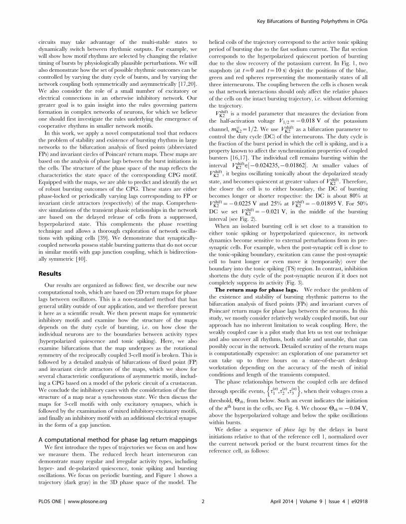
Figure 19. Asymmetric motifs that only exhibit phase slipping. (A) Here, gsyn12 ~g
syn21 ~1:5gsyn and g
syn13 ~g
syn31 ~0:8gsyn. The phase lag map
possesses only one attractor: the invariant curve corresponding to the phase slipping regime. (B) Voltage traces showing phase slipping beginningwith the 2\f1E3gð Þ rhythm and continuously transitioning into the clockwise 1[2[3ð Þ traveling wave, followed by the 1\f2E3gð Þ rhythm, andbeing continued by the counter-clockwise 1[3[2ð Þ traveling wave and coming back to the initial 2\f1E3gð Þ rhythm in nine bursting cycles.doi:10.1371/journal.pone.0092918.g019
Key Bifurcations of Bursting Polyrhythms in CPGs
PLOS ONE | www.plosone.org 15 April 2014 | Volume 9 | Issue 4 | e92918

Next, in addition to gsyn13 , the second outgoing connection, g
syn12 ,
from cell 1 is strengthened thus breaking the clockwise symmetry
as well. As expected, this eliminates the FP at 13
, 23
� �and the
corresponding clockwise 1[2[3ð Þ traveling pattern from the
motif. Figure 17B shows the map for the motif with
gsyn12 ~g
syn13 ~1:5gsyn. While it retains all three ‘‘pacemaker’’ FPs,
the one at 12
, 12
� �corresponding to the strongly inhibiting pre-
synaptic cell 1 possess the largest attractor basin.
We may conclude that strengthening a single directional
connection, or alternatively, a simultaneous and proportional
weakening coupling strengths of the two synaptic connections of
the same orientation in the motif, controls one of the three saddle
points between the FP corresponding to traveling waves and the
pacemaker FP corresponding to the stronger inhibiting cell. This
will eventually causes the disappearance of either point as soon as
the rotational symmetry is broken after the coupling strength is
increased over some critical value, which varies depending on the
nominal value gsyn and the duty cycle of the bursting cells.
Motifs with a stronger coupled HCO: loss of phase-
locking. A 3-cell motif with the cells coupled reciprocally by
inhibitory synapses can be viewed alternatively as a group of three
half-center oscillators (HCO). Each HCO represents a pair of cells
that typically burst in anti-phase, when isolated from other cells.
When a HCO is symmetrically driven, even weakly, by another
bursting cell, it can produce in-phase bursting, instead of out of
phase bursting [16].
In this section, we consider transformations of rhythmic
outcomes in the motif containing a single HCO with stronger
reciprocally inhibitory connections, for example,
gsyn12 ~g
syn21 ~1:25gsyn (see Fig. 18A). It turns out that a 25%
increase in coupling is sufficient to break both rotational
symmetries because it eliminates the associated FPs around13
, 23
� �and 1
3, 2
3
� �through saddle-node bifurcations. Since both
connections are strengthened simultaneously, the attractor basins
of the both dominating FPs, blue near 12
, 12
� �and green near 1
2,0
� �,
widen equally. However, increasing the connections gsyn12 and g
syn21
between cells 1 and 2 does not affect the attractor basin of the red
FP at 0, 12
� �. In other words, the motif can still produce the co-
existing 3\f1E2gð Þ rhythm.
The following bifurcation sequence involving the dominant FP
differs drastically from the saddle-node bifurcations discussed
earlier. Observe from the map in Fig. 18A that two saddles
separating two attractor basins, have moved close to the blue and
green FPs as the coupling between the HCO cells is increased to
1:5gsyn. This is a direct indication that a further increase of the
coupling strength between the strongly inhibitory cells 1 and 2 will
cause two simultaneous saddle-node bifurcations that eliminate
both stable FPs.
A feature of these bifurcations of the map at the critical moment
is that there are two heteroclinic connections that bridge the saddle-
node FPs on the 2D torus. The breakdown of the heteroclinic
connections with the disappearance of both FPs results in the
emergence of a stable invariant circle that wraps around the torus
[41,42]. The attractor basin of the new invariant curve is bounded
away from that of the red FP at 0, 12
� �by the stable sets (i.e.,
incoming separatrices) of the two remaining saddles. This motif is
therefore bi-stable as the corresponding map shows two co-existing
attractors.
Further increase in the coupling strength between the stronger
inhibitory HCO and cell 3 cannot not qualitatively change the
structure of the phase lag map, while it can have only a
qualitatively effect on the size of the attractor basins of the
invariant circle and the remaining FP (red). So, weakening
gsyn31 ~g
syn32 ~0:8gsyn makes the separating saddles come closer to
the red FP and hence shrink its attractor basin, as seen in Fig. 18B.
This is not the case when either connection between cell 3 and
the HCO is made sufficiently asymmetric. Depending on the
connection’s direction of asymmetry, such an imbalance causes
either of the two remaining saddles to come close and annihilate
with the stable red FP at 12
,0� �
. Figure 19 presents the map for this
motif with weakened reciprocal connections between cells 3 and 1:
gsyn13 ~g
syn31 ~0:8gsyn. This motif, comprised of three HCOs with
strong, nominal and weak reciprocal connections, no longer
produces any phase-locked bursting rhythm, including
3\f1E2gð Þ, as the map no longer has any stable FPs. The
resulting motif is monostable with a single attractor for the stable
invariant curve. This curve can be characterized with a rational or
irrational winding number. The number is a rational if the invariant
curve is made of a finite number of periodic points across the
torus.
The occurrence of the stable invariant curve wrapping around
the torus gives rise to a phase slipping phenomenon observed in
voltage traces such as those shown in Fig. 19B. We define ‘‘phase
slipping’’ as a repetitive rhythm with varying phase lags between
the bursting cells of the motif. The period of the invariant circle
depends on how far the map with the invariant circle is from the
bifurcations of ‘‘ghost’’ FPs. The ‘‘ghosts’’ make the bursting
Figure 20. Asymmetric motif with strong connections to cell 3.Motif with cell 3 receiving inhibition stronger than the nominal value:g
syn13 ~g
syn23 ~1:6gsyn. Such strong asymmetry means the map no longer
possesses the traveling wave or the blue and green pacemaking FPs,similar to that shown in Fig. B. There is bi-stability between the tworemaining attractors, i.e. the stable red FP at 1
2,0
� �and the stable
invariant curve. The stable invariant curve ‘‘flows’’ upwards, because theperiod of cell 3 is longer than the period of cells 1 and 2.doi:10.1371/journal.pone.0092918.g020
Key Bifurcations of Bursting Polyrhythms in CPGs
PLOS ONE | www.plosone.org 16 April 2014 | Volume 9 | Issue 4 | e92918

pattern with varying phase lags appear as it is composed of four
sequential episodes and transitions between them.
From the top of the Dw21,Dw31ð Þ-unit square, the curve begins
with the 2\f1E3gð Þ rhythm continuously transitioning into the
clockwise 1[2[3ð Þ traveling wave, followed by the 1\f2E3gð Þrhythm, and being followed by the counter-clockwise 1[3[2ð Þtraveling wave and finally returning to the initial 2\f1E3gð Þrhythm in nine bursting cycles, which is the period of the phase
slipping. Each episode of the phase slipping rhythm can be
arbitrarily large as it is controlled by the coupling strength of the
specific motif connections near the corresponding saddle-node
bifurcation(s). Observe that Dw21^12
on the invariant curve, i.e.,
while cell 1 and 2 are in anti-phase bursting, cell 3 modulates the
rhythm by recurrently slowing down and advancing the HCO to
generate continuously all four episodes.
One may wonder about what determines the direction of the
invariant curve on the torus and hence the order of the episodes of
the shown voltage waveform. Observe that the phase slip occurs in
the Dw31 direction and that the invariant curve, unlike a FP, has
no fixed period for the whole network. Indeed, the recurrent times
of this network change periodically, approximately every eight
episodes. The eight episodes constituting the bursting pattern are
determined by a rational ratio of the longer HCO period (due to
stronger reciprocal inhibition that extends the HCO interburst
intervals) to the shorter period of pre-synaptic cell 3 (due to a
weaker incoming inhibition) (see Figs. 19B and 20).
Let us discuss another motif configuration, shown in Fig. 18B,
that produces maps with stable invariant curves that wrap around
the torus. These are qualitatively identical to the maps for the
motif containing the strong HCO formed by cells 1 and 2
(Fig. 18A). In this configuration, cell 3 receives weaker inhibition
from pre-synaptic cells 1 and 2 according to gsyn13 ~g
syn23 ~0:6gsyn.
The de-stabilizing factor 0.6 turns out to be small enough to make
sure that neither cell 1 nor 2 can be a pacemaker as the
corresponding stable FPs have disappeared because the period of
cell 3 has become shorter than the periods of cells 1 and 2. As the
result, the map demonstrates the same stable invariant curve that
‘‘flows’’ downwards with decreasing Dw31 phase lags.
The direction of the stable invariant circle flowing across the 2D
torus can be reversed by making cell 3 receive stronger inhibition
instead of weaker inhibition relative to the other cells. An example
is depicted in the phase lag map of Fig. 20, where
gsyn13 ~g
syn23 ~1:6gsyn.
Toward control of multistability. We now elucidate the
issues involved in designing inhibitory motifs with predetermined
bursting outcomes and how to control them. Let us revisit the
motif with a single HCO in Fig. 17A. The map is depicted near
the bifurcations that eliminate both blue and green FPs
simultaneously as the coupling strength between cells 1 and 2 is
increased. The corresponding saddle-node bifurcations are each of
co-dimension one, i.e. can be unfolded by a single parameter. This
means that increasing either coupling parameter, gsyn12 or g
syn21 ,
makes the respective FP at 12
,0� �
(green) or 12
, 12
� �(blue) disappear
or re-emerge. This suggests alternative ways of perturbing the
motif to get the desired outcome. For instance, in the motif with
Figure 21. Motifs with the asymmetric inhibition to cell 3. (A) The phase lag map for the medium duty cycle motif at gsyn12 ~g
syn21 ~g
syn23 ~1:5gsyn
generates two phase-locked bursting rhythms. There is a dominant 2\f1E3gð Þ rhythm due to the large attractor basin of the green FP at 12
,0� �
, and
the 3\f1E2gð Þ rhythm corresponding to the red attractor at 0, 12
� �which has a smaller basin. (B) Here, g
syn12 ~g
syn21 ~g
syn13 ~1:5gsyn. In the corresponding
phase lag map, the stable FP at 12
, 12
� �has a larger attractor basin compared to that of the coexisting FP for cell 3 that leads the 3\f1E2gð Þ rhythm.
doi:10.1371/journal.pone.0092918.g021
Key Bifurcations of Bursting Polyrhythms in CPGs
PLOS ONE | www.plosone.org 17 April 2014 | Volume 9 | Issue 4 | e92918

the HCO given by gsyn12 ~g
syn21 ~1:5gsyn, cell 2 can be made the
strongest on the motif by increasing the outgoing inhibitory drive:
gsyn23 ~1:5gsyn. The green FP at 1
2,0
� �in the corresponding map in
Fig. 21A has a largest attraction basin that guarantees the
dominance of the 2\f1E3gð Þ-rhythm over the network. The map
in Fig. 21B has the basin of the blue FP at 12
, 12
� �largest, after
strengthening the coupling from cell 1 to 3 in the motif with two
robust bursting outcomes: the 1\f2E3gð Þ-rhythm dominating
over the 3\f1E2gð Þ-rhythm corresponding to the red FP at 0, 12
� �with a smaller basin formed by initial phases.
The above configurations of the inhibitory motif are bistable
with two coexisting FPs: dominant blue (or green) with a large
attractor basin and red with a smaller basin corresponding to the
less robust 3\f1E2gð Þ rhythm. To construct the monostable motif
with the single rhythm, for example 1\f2E3gð Þ, cell 1 must be
coupled reciprocally stronger with cell 3 than cell 2. Such a motif has
two HCOs that both contain cell 1 due to the strengthened pairs of
synaptic connections: gsyn12 ~g
syn21 ~1:5gsyn and g
syn13 ~g
syn31 ~
1:5gsyn. The corresponding map for the phase lags is shown in
Fig. 22. The resulting map demonstrates that both the red and
green FPs have been annihilated, as well as the corresponding
bursting rhythms. Note that the map still has two saddle FPs in
addition to the only attractor at 12
, 12
� �. It is a feature of a map on a
2D torus that the number of FPs must be even, in general, for
them to emerge and vanish through saddle-node bifurcations.
Therefore, the map must possess another hyperbolic FP. This
point resides near the origin where all three cells burst
synchronously, which we consider next.
Fine structure near the origin. A common misconception
concerning modeling studies of coupled cells is that fast, non-
delayed inhibitory synapses always foster anti-phase dynamics over
unstable in-phase bursting. While being true in general for simple
relaxation oscillators, interactions of bursting cells can be
incomparably more complex even in small networks including
HCOs with fast inhibitory coupling [16,27]. It was shown in [28]
that overlapped bursters can reciprocally synchronize each other
in multiple, less robust, phase-locked states due to spike
interactions. Furthermore, the number of such synchronous steady
states is correlated with the number of spikes within the
overlapped bursts.
To explore the dual role of inhibition, we now explore nearly
synchronous bursting in all three cells of the homogeneous,
medium DC motif. Because synchronous steady states are due to
spike interactions, we restrict the consideration to a relatively small
positive vicinity of the synchronous state, Dw21~Dw31~0, in P. A
magnified portion of the map is shown in Fig. 23, where green, red
and black dots denote the locations of the stable, repelling and
saddle (threshold) phase locked states (respectively) for the nearly
synchronized bursting outcomes. The map reveals that several
overlapping burst patterns can occur where either cell spikes
slightly in advance or delayed compared to the reference cell.
Unstable FPs surround the outer part of this small region of the
map make the origin repelling in the map on the global scale.
Excitatory motifsIn this section, we discuss a variation of a homogeneous 3-cell
motif with short, 25% DC at V shiftK2 ~{0:01895 V, will all three
excitatory synaptic connections. The synaptic current is again
given through the FTM paradigm:
Isyn~gsyn(Esyn{Vpost)C(Vpre{Hsyn). The synapses are made
Figure 22. A motif with cell 1 leading in two half-centeroscil lators. The phase lag map at g
syn12 ~g
syn21 1:5gsyn and
gsyn13 ~g
syn31 ~1:5gsyn has a single phase-locked attractor – the blue FP
at 12
, 12
� �corresponding to the unique rhythm, 1\f2E3gð Þ.
doi:10.1371/journal.pone.0092918.g022
Figure 23. Fine dynamical structure near the originDw21~Dw31~0 of the phase lag map. Green, red, and black dotsdenote stable, repelling, and saddle FPs (resp.) in the vicinity of theorigin, corresponding to all three cells almost synchronized in thehomogenous medium-bursting motif. Globally, at a larger scale, theorigin appears unstable.doi:10.1371/journal.pone.0092918.g023
Key Bifurcations of Bursting Polyrhythms in CPGs
PLOS ONE | www.plosone.org 18 April 2014 | Volume 9 | Issue 4 | e92918

more excitatory by increasing the synaptic reversal potential, Esyn,
from {0:0625 V (corresponding to the inhibitory case) to 0:0 V.
Esyn~0 guarantees that the voltages of all the cells remain below
the reversal potential, on average, over the bursting period. In the
excitatory motif, whenever the advanced cell initiatives a new
bursting cycle, the synaptic current raises the voltages of post-
synaptic cells, thus making it follow the pre-synaptic one, at the
hyperpolarized knee-point on the quiescent manifold (Fig. 1B).
Figure 6 shows the phase lag map for the original inhibitory
motif with three stable FPs (shown in blue, red and green) at
Dw21,Dw31ð Þ~ 12
, 12
� �, 0, 1
2
� �, 1
2,0
� �and two unstable FPs (dark dots)
at 23
, 13
� �and 1
3, 2
3
� �. The attractor basins of three stable FPs are
separated by the separatrices of six saddle FPs (smaller dots). A
small area around the origin is globally repelling. This motif can
stably produce three coexisting patterns in which either cell bursts
in anti-phase with the two remaining in-phase.
It is often presumed in neuroscience that excitation acts
symmetrically opposite to inhibition in most cases, i.e. wherever
inhibition tends to break synchrony, excitation fosters it. Figure 24
supports this assertion for this particular kind of network and
coupling. It depicts the map corresponding to the homogeneous 3-
cell motif with reciprocally excitatory connections for same short,
25% DC.
Compared to the map for the inhibitory motif, the map for the
homogeneously excitatory motif is the inverse:
P{1 : Dw(nz1)21 ,Dw
(nz1)31
� �? Dw
(n)21 ,Dw
(n)31
� �; here the inverse is
the forward map in discrete backward time. As such, the FPs at13
, 23
� �and 2
3, 1
3
� �, which used to be repelling in the inhibitory case,
become attracting but with smaller basins. This means that the
motif can generate traveling waves, albeit with low probability.
Meanwhile, the FPs colored blue, green and red, are now
repellers, and hence none of the pacemaker rhythms can occur.
Reversing the stability does not change the topological type of the
six saddles, but their stable and unstable separatrices are reversed.
The dominant attractor of the map is now located at the origin, to
which nearly all transient trajectories converge. This implies that
the reciprocally excitatory motif, whether homogeneous or
heterogeneous, will exhibit stable synchronous bursting with all
three cells oscillating in-phase.
Mixed motifsHere we discuss two intermediate configurations of mixed
motifs having both inhibitory and excitatory connections. First, we
consider the motif with a single excitatory connection from cell 3
to 1. Its coupling strength is regulated by the level of the synaptic
reversal potential, E31syn. Figure 25 depicts three phase lag maps for
the motif with Esyn being increased from {0:050, {0:030
through 0:0 V.
Initially, an increase in E31syn gives rise to two saddle-node
bifurcations in the motif (Fig. 25A): the first one breaks the
clockwise rotational symmetry and hence annihilates the stable FP
at 13
, 23
� �. The second bifurcation annihilates the stable red point at
0, 12
� �, because cell 3, inhibiting 2 and exciting 1, cannot hold both
of them at the hyperpolarized quiescent state to generate the
3\f1E2gð Þ-rhythm as it promotes burst initiation in cell 1
following those in cell 3. On the contrary, excitation applied to
cell 1 forces it to follow cell 3 after a short delay in the burst
initiation. As the result, the disappearance of the 3\f1E2gð Þ-rhythm promotes the 2\f1E3gð Þ-rhythm and an increase of the
attractor basin of the green FP.
Initial elevations of the level of E31syn keep the other three FPs
intact, while widening the basins of the blue and green stable FPs
at 12
, 12
� �and 1
2,0
� �. Further increasing E31
syn increases the duty
cycle of the blue cell by extending its active bursting phase.
Consequently, the counter-clockwise ring no longer contains
identical cells that could orchestrate the 1[3[2ð Þ pattern. This
patten is eliminated with the disappearance of the corresponding
FP at 23
, 13
� �through a merger with a saddle. The map now has two
persistent attractors, blue and green, as shown in Fig. 25B. With
E31syn increased still further, the blue cell 1 receives strongly
unbalanced input: larger excitation influx from the postsynaptic
cell 3 and an inhibitory drive from cell 2, acting oppositely. This
unbalanced input increases the active phase of bursting of cell 1
and hence its duty cycle and period, and hence breaks cell 1’s
ability to robustly maintain the 1\f2E3gð Þ-rhythm by evenly
inhibiting the pots-synaptic cells 1 and 2 of the same period. In P,
this results in the shrinking of the attractor basin of the blue FP,
whereas the basin of the dominating green FP widens. By setting
E31syn~0:0 V, the resulting strong imbalance between excitation
and inhibition onto cell 1 makes the 1\f2E3gð Þ-rhythm
impossible to occur in the network and the corresponding FP at12
, 12
� �disappears in the map. After this last saddle-node
bifurcation, the map has a unique attractor in the green FP.
Eventually, regardless of initial phases, the synergetic interaction of
Figure 24. Phase lag map for the excitatory, weakly coupled,homogeneous motif with short duty cycle. With gsyn~5|10{4 ,this map has a dominant attractor at the origin that corresponds tosynchronous bursting. Also depicted are three repelling FPs (blue, redand green) at Dw21,Dw31ð Þ~ 1
2, 1
2
� �, 0, 1
2
� �, and 1
2,0
� �, as well as stable FPs
at 23
, 13
� �and 1
3, 2
3
� �with small attractor basins, corresponding to
traveling waves, co-existing with the synchronous bursting.doi:10.1371/journal.pone.0092918.g024
Key Bifurcations of Bursting Polyrhythms in CPGs
PLOS ONE | www.plosone.org 19 April 2014 | Volume 9 | Issue 4 | e92918

inhibitory and excitatory cells in this mixed motif will give rise to
the 2\f1E3gð Þ-rhythm led by cell 2 (Fig. 26).
Finally, we consider the mixed motif with two excitatory
connections originating from cell 3. Figure 27 depicts the
transformations of the P as the reversal potentials, E31syn and
E32syn, are increased simultaneously from {0:050, {0:030 through
to {0:020 V. The increase makes postsynaptic cells 1 and 2 more
excited compared to cell 3, which consequently receives a longer
duration of inhibition.
As in the previous case, increasing E31syn~E32
syn~{0:050 V
breaks both rotational symmetries, which is accompanied by the
disappearance of the corresponding, counter-clockwise and
clockwise, FPs. The increased excitability of cells 1 and 2 initiates
the active bursting states of those cells soon after that of cell 3 in
each cycle. Thus, the 3\f1E2gð Þ-rhythm led by cell 3 is less likely
to occur compared to the 1\f2E3gð Þ and 2\f1E3gð Þ- rhythms.
The corresponding (red) FP at 0, 12
� �loses the attractor basin in the
map and then disappears, following the FPs for the traveling
waves, at {0:030 V, see Fig. 27B. After that, the blue and green
stable points have equal attractor basins corresponding to equal
chances of the emergence of the phase-locked rhythms 1\f2E3gð Þand 2\f1E3gð Þ. Examination of the map suggests that besides
these phase-locked rhythms, the motif can generate long transients
Figure 25. Phase lag maps for the mixed homogeneous motif with medium duty cycle as reversal potential varies. With gsyn~0:0005,maps are depicted for E31
syn~{0:050 in (A), {0:030 in (B) and {0:020 V in (C). (A) Increasing E31syn causes two saddle-node bifurcations: one breaks
the clockwise rotational symmetry and annihilates the corresponding FP at 13
, 23
� �, while the other annihilates the stable red point at 0, 1
2
� �. (B) This
widens the basins of the blue and green stable FPs at 12
, 12
� �and 1
2,0
� �. Further raising E31
syn eliminates the attractor basin for the black FP at 23
, 13
� �in
(B), and finally the blue FP along with the 1\f2E3gð Þ- rhythm in (C). Black-labeled trajectories indicate the direction field on the torus and theseparatrices of saddles.doi:10.1371/journal.pone.0092918.g025
Key Bifurcations of Bursting Polyrhythms in CPGs
PLOS ONE | www.plosone.org 20 April 2014 | Volume 9 | Issue 4 | e92918

with episodes that resemble those of the 3\f1E2gð Þ-rhythm
transitioning back and forth with in-phase bursting. Such
transients are due to regions of the map that are constrained by
the incoming separatrices of the remaining saddles, which are
forced to curve in complex ways to embed onto the torus with two
attractors and an unstable origin. Note that the origin may not
longer be a repeller as a whole but has a saddle structure, because
it is no longer associated with synchronous bursting.
Setting the excitatory reversal potential to zero annihilates the
two remaining phase-locked states (blue and green FPs) in two
simultaneous bifurcations. As with the case of the inhibitory motif
with the HCO (compare with Fig. 18), these global bifurcations
underlie the formation of a closed heteroclinic connection between
the saddle-node points at the critical moment. These connections
transform into an invariant circle that wraps around the torus.
Having settled onto the invariant curve that zigzags over the torus,
the network will generate long recurrent patterns consisting of
three transient episodes: namely, in-phase bursting that transitions
to the 1\f2E3gð Þ-rhythm, which transitions back to in-phase
bursting, then transitioning to the 2\f1E3gð Þ-rhythm, which then
returns to the in-phase bursting, and so forth.
At higher values of reversal potentials, excitation overpowers
inhibition and this mixed motif fully becomes the excitatory motif
with the single, all-synchronous, bursting rhythm forced by the
driving cell 3. In the corresponding return map, this rhythm
occurs after the invariant curve terminates at a homoclinic
connection to a saddle-node near the origin so that the origin
becomes a global attractor again.
Gap junction in an inhibitory motifFinally, let us consider the role of a single electrical synapse
though a gap junction between cells 1 and 2 in the inhibitory motif
(Fig. 1A). The difference in the membrane potentials gives rise to a
directional ohmic current described by Iel~gel (V2{V1) in the
model (3). Figure 28 depicts the stages of transformation of the
corresponding maps as gel is increased from 10{4 through
3|10{4.
The electrical coupling breaks down the rotational symmetry
that causes the disappearance of the corresponding FPs at 13
, 23
� �and 2
3, 1
3
� �. The disappearance of both FPs widens the attraction
basin of the red FP at 0, 12
� �compared to the individual basins of
the blue and green FPs. The bidirectional electrical coupling tends
to equilibriate the membrane potentials of the connected cells, so
that cell 1 and 2 are brought closer together to burst in synchrony,
rather than in alternation. At intermediate values of gel , inhibitory
coupling can still withstand the tendency to synchronize cells 1 and
2, while the red basin widens further due to shrinking basins of the
blue and green FP. At larger values of gel , synchrony of bursting
cells 1 and 2 overpowers their reciprocal inhibition, and the motif
generates only the 3\f1E2gð Þ-rhythm regardless of the choice of
initial phases. Thus, we find that motifs with strong electrical
synapses describe a dedicated rather than a multifunctional CPG.
Discussion
Our new computational technique reduces the dynamics of a 9-
dimensional network motif of three cells to the analysis of the 2D
maps for the phase lags between the bursting cells. With this
technique, we demonstrated that a reciprocally inhibitory network
can be multistable, i.e. can generate several distinct polyrhythmic
bursting patterns. We studied both homogeneous and non-
homogeneous coupling scenarios as well as mixtures of inhibition,
excitation and electrical coupling. We showed that the observable
rhythms of the 3-cell motif are determined not only by symmetry
considerations but also by the duty cycle, which serves as an order
parameter for bursting networks. The knowledge of the existence,
stability and possible bifurcations of polyrhythms in this 9D motif
composed of the interneuron models is vital for derivations of
reduced, phenomenologically accurate phase models for non-
homogeneous biological CPGs with inhibitory synapses.
The idea underlying our computational tool is inspired by
common features of electrophysiological experimentation. As such,
it requires only the voltage recording from the model cells and
does not explicitly rely on the gating variables. We intentionally
choose the phases based on voltage as often this the only
experimentally measurable variable. Moreover, as with real
experiments, we can control the initial phase distribution by
releasing the interneurons from inhibition at specific times relative
to the reference neuron. Our analysis of the system only utilizes
the qualitative, geometric tools of dynamical systems theory. Thus,
although in this example we simulated a system of underlying
differential equations to generate the maps, in principle such maps
could be generated and analyzed directly from experimental data.
In this sense, our method does not require knowledge of explicit
model equations.
Summary and interpretation of main resultsRhythmic motor behaviors, such as heartbeat, respiration,
chewing, and locomotion are often independently produced by
small networks of neurons called Central Pattern Generators
(CPGs). It is not clear either what mechanisms a single motor
system can use to generate multiple rhythms, for instance: whether
CPGs use dedicated circuitry for each function or whether the
Figure 26. Transient voltage traces converging to the 2\f1E3gð Þ-rhythm generated by a mixed motif. Here, E31syn~{0:020 V, which
corresponds to the phase lag map having a single attractor at the green FP in Fig. 25C; here stronger gsyn~0:005 was used for the sake of illustrationof a quicker convergence.doi:10.1371/journal.pone.0092918.g026
Key Bifurcations of Bursting Polyrhythms in CPGs
PLOS ONE | www.plosone.org 21 April 2014 | Volume 9 | Issue 4 | e92918

same circuitry can govern several behaviors. A systematic way to
explore this is to create mathematical models that use biologically
plausible components and classify the possible varieties of
rhythmic outcomes.
We performed such a study of CPG networks based on three
inter-connected neurons. We systematically varied the strength
and functional form of coupling between the neurons to discover
how these affect the behavioral repertoire of the CPG. To do this,
we created a geometric representation of the simulated CPG
behavior of each possible configuration of the network, which
greatly simplifies the study of the 9-dimensional system of
nonlinear differential equations. We discovered several configura-
tions that support multiple rhythms and characterized their
robustness. By varying physiologically reasonable parameters in
the model, we also describe mechanisms by which a biological
system could be switched between its multiple stable rhythmic
states.
In the Homogeneous Inhibitory Motifs section, we showed that
a weakly coupled, homogeneous motif comprised of three bursting
interneurons with reciprocally inhibitory fast synapses can produce
a variable number of polyrhythms, depending on the duty cycle of
the individual components. The phase lag maps are de facto proof
of the robust occurrence of the corresponding rhythmic outcomes
generated by such a motif. While the occurrence of some rhythms,
Figure 27. Phase lag maps for the mixed motifs as an excitatory reversal potential varies. Here, we choose values {0:050, {0:030 and{0:010 V, for the reversal potential, Esyn in the two excitatory connections originating from cell 3. (A) Increasing Esyn causes two saddle-node
bifurcations, and breaks the rotational symmetries and hence annihilates the FPs at 23
, 13
� �and 1
3, 2
3
� �. This widens the basins of the blue and green
stable FPs at 12
, 12
� �and 1
2,0
� �, and shrinks that of the red stable FP at 0, 1
2
� �. (B) Making two connections more excitatory produces a closed
heteroclinic connection between the remaining FPs, which becomes a stable invariant circle wrapped around the torus (inset C). Black-labeledtrajectories indicate the direction field on the torus and the separatrices of saddles.doi:10.1371/journal.pone.0092918.g027
Key Bifurcations of Bursting Polyrhythms in CPGs
PLOS ONE | www.plosone.org 22 April 2014 | Volume 9 | Issue 4 | e92918

such as 1[2[3ð Þ and 1[3[2ð Þ, in a 3-cell motif can
hypothetically be deduced using symmetry arguments; the
existence and robustness of the rhythms can be only verified by
accurate computations of the corresponding return maps. More-
over, the observability of these rhythms in even the homogeneous
motifs, and the stability of the FPs, are both closely linked to the
temporal properties of the bursts.
Recall that the inhibitory current shifts the post-synaptic cell
closer to the boundary or can even move it over the boundary into
silence while the pre-synaptic cell remains actively spiking (Fig. 3).
In terms of dynamical systems theory, this means that the
perturbed driven system closes the gap between the hyperpolar-
ized fold and the slow nullcline m0
K2~0, eventually causing the
emergence of a stable equilibrium state on the quiescent branch.
As such, the homogeneous network produces three pacemaker
rhythms, 3\f1E2gð Þ, 2\f1E3gð Þ, and 1\f2E3gð Þ – the only
rhythms available in the short motif. These strongly synchronized
activities imply fast convergence to the phase locked states because
of the emergent equilibrium state near the closed gap: compare the
time spans in Figs. 6A and 9A.
The gap never gets closed by weak inhibition in the long duty
cycle motif as the individual cells have initially remained far
enough from the boundary separating the bursting and hyperpo-
larized quiescence. As the result, this motif can only effectively
produce two possible bursting outcomes: the clockwise 1[2[3ð Þand counter-clockwise 1[3[2ð Þ traveling waves. This bistability
Figure 28. Transformation stages of the phase lag map for the inhibitory motif with a single gap junction between cells 1 and 2.Increasing the electrical coupling strength from 10{4 through 3|10{4 transforms the multistable motif into a dedicated one by eliminating first theFPs corresponding to the traveling waves, and next the green and blue FPs at the same time as the gap junction is bi-directional. Eventually, the redFP 0, 1
2
� �, corresponding to the single 3\f1E2gð Þ-rhythm led by cell 3 in the motif with the gap junction uniting bursting cells 1 and 2, becomes the
global attractor of the map.doi:10.1371/journal.pone.0092918.g028
Key Bifurcations of Bursting Polyrhythms in CPGs
PLOS ONE | www.plosone.org 23 April 2014 | Volume 9 | Issue 4 | e92918

results from a weaker form of synchronization, which is confirmed
by the rate of convergence to the FPs. This will not be the case
when the inhibition becomes stronger due to increasing the
nominal coupling strength, gsyn.
The intermediate case of the medium motif is far from the
above extremes and benefits from a natural optimization between
the coupling strength, initial phase distributions, and the spatio-
temporal characteristics of unperturbed and perturbed bursting.
One such characteristic is the slow passage through the ghost of
the stable equilibrium state that guarantees the robust synchrony
in the short duty cycle motif. As the result, the motif can produce
five stable bursting rhythms: the anti-phase 3\f1E2gð Þ,2\f1E3gð Þ, and 1\f2E3gð Þ; and the clockwise 1[2[3ð Þ and
counter-clockwise 1[3[2ð Þ traveling waves.
In the Asymmetric Inhibitory Motifs section, we described a
number of generic bifurcations of the original five polyrhythms
that can occur in the homogeneous, reciprocally inhibitory motif
with the medium duty cycle. We revealed the basic principles of
transformations of such a multi-functional network into ones with
fewer rhythms or even with a single pattern bursting pattern.
The rhythmic outcomes of the CPG do not always have to
involve phase locking, as there can be a stable pattern of phase
slipping bursts that have time varying phase lags.
While each rhythm remains robust with respect to variations of
the coupling connections, one can still make the network switch
between them by applying an external pulse to the targeted cell
that, upon release, appropriately changes the relative phases of the
cells, as demonstrated in Fig. 10 for the medium duty cycle motif.
In terms of the Poincare return maps for the phase lag, switching
between rhythms is interpreted as switching between the
corresponding attractor basins of FPs or invariant circles. This
causes the state of the network to ‘‘jump’’ over the separating
threshold defined by a saddle (more precisely, over the incoming
separatrices of the saddle). We stress, however, that the choice of
timing in the suppression of a targeted cell to effectively switch
between these polyrhythms is not intuitive and requires a detailed
understanding of the underlying dynamics.
Although there are alternative ways of creating the 3-cell
reciprocally inhibitory motif with predetermined outcomes, the
fundamental principles are universal: the pre-synaptic cell that
produces stronger inhibition gains the larger attractor basin and
therefore the corresponding rhythm led by this cell becomes
predominant. In particular, a sufficient increase (or decrease) of
the coupling strength of a single connection can break the intrinsic
rotational symmetry of the motif to remove the possibility of
observing traveling wave patterns.
Of special interest are the motifs with asynchronous phase-
slipping patterns that have no dominating phase-locked states.
Such patterns result from the synergetic interactions between all
contributing cells, and is comprised of four transient episodes, but
primarily marked by a continuous transition between two primary
sub-rhythms: 2\f1E3gð Þ and 1\f2E3gð Þ (for example, see
Fig. 20). Both competing sub-rhythms are equally possible, and
none can prevail over the other without the weaker inhibiting cell
3 whose reciprocal connections change the existing balance by
shifting the phase lags during all four episodes.
In all cases we have considered, inhibition was chosen weak
enough to guarantee that the post-synaptic cell remains in a
bursting state even when its duty cycle decreases to 20% near the
boundary between bursting and silence. This ensures that the
phases of the cells, as well as the phase lags, are well defined for the
return maps. However, this assumption may fail, for example
when phase of a post-synaptic cell is not defined because the
incoming synaptic inhibition makes it quiescent [17]. This leads to
a phenomenon called sudden death of bursting that occurs when a
rhythmic leader (red cell 3 in Fig. 29) becomes suppressed by the
Figure 29. Sudden death of bursting in cell 3 after application of an inhibitory stimulus to cell 1. An inhibitory stimulus causes the switchfrom the 3\f1E2gð Þ rhythm, led by cell 3, to a pattern where it is forced to become hyperpolarized quiescent. This state is due to cell 3 receivingcontinuous inhibition by the half-center oscillator formed by cells 1 and 2 in an asymmetric motif at g
syn13 ~g
syn23 ~6gsyn and g
syn31 ~g
syn32 ~0:4gsyn.
doi:10.1371/journal.pone.0092918.g029
Figure 30. Sketch of nested synchronization zones in theparameter space of the network. The synchronization zones are theexistence regions of co-existing stable FPs corresponding to variousphase-locked bursting patterns of the CPG. The boundaries of the zonesare crossed when a single bifurcation parameter Dg
synij (e.g. one of the
coupling strengths) is varied from a nominal value so that it causes asequence of saddle-node bifurcations that eliminate FPs and corre-sponding patterns from the network dynamics.doi:10.1371/journal.pone.0092918.g030
Key Bifurcations of Bursting Polyrhythms in CPGs
PLOS ONE | www.plosone.org 24 April 2014 | Volume 9 | Issue 4 | e92918

other two cells that form an anti-phase HCO, which alternately
inhibit the post-synaptic cell. In our example, the outgoing
inhibition from cell 3 is several times weaker than the inhibition
that it receives from the HCO formed by cells 1 and 2:
gsyn31 ~g
syn32 ~0:4gsyn and g
syn13 ~g
syn23 ~6gsyn (this ratio does not
always have to be as large when gsyn is increased).
It should be stressed that the sudden death of bursting co-exists
with other bursting patterns in the motif at the same coupling
parameters. As such, this example bears a close qualitative
resemblance to the experimental recordings from identified
interneurons comprising the leech heart CPG in which the so-
called switch interneuron alternately leads synchronous patterns
and then becomes inactive during peristaltic patterns [43–45].
Analogous reversions of direction in the blood circulation,
peristaltic and synchronous, are observed in the leech heartbeat
CPG and its models [21,46]. The contrast between the patterns is
that switching appears to be autonomously periodic in the leech,
i.e. occurs without external stimulus, in a way similar to the phase-
slipping pattern presented in Fig. 19.
Examination of the complex fine structure of the map near the
origin reconfirms that fast, non-delayed inhibition can have
stabilizing effects leading to the onset of several nearly synchro-
nous bursting patterns with several overlapping spikes [28]. Such
bursting patterns are less robust compared to those corresponding
to FPs with large attractor basins in the phase lag maps.
We showed in the Excitatory Motifs section that raising the
synaptic reversal potential is equivalent to reversing the time in the
inhibitory motif model. In the maps, this action transforms
attractors into repellers, while saddles remain saddles but have
their incoming and outgoing directions reversed. To fully illustrate
this phenomenon, we used the symmetric motif with the short duty
cycle, in which the clockwise and counter-clockwise traveling
waves are unstable. In the symmetric counterpart with excitatory
synapses, these FPs become the attractors along with the dominant
fixed point at the origin corresponding to synchronous bursting.
In the Mixed Motifs section we analyzed the transformation of
the maps corresponding to the motifs with mixed, inhibitory and
excitatory synapses. We showed step-by-step how the the multi-
functional motif becomes a dedicated motif. The final example
was the mixed motif with two excitatory connections. Unlike the
former case, such a monostable motif possesses a bursting rhythm
with time varying phase lags, which corresponds to a stable
invariant curve wrapping around the 2D torus.
Conclusions and future workWe emphasize that a highly detailed examination of the
occurrence and robustness of bursting patterns in the 3-cell motifs
would be impossible without the reduction of the complex 9D
network model with six algebraic equations for chemical synapses
to the 2D maps and the numerical bifurcation analysis of FPs,
invariant circles, homoclinic structures in it. Recall that the
dimension of the map is determined by the number of the nodes in
the network, not the number of differential equations per synapse
and per neuron, which can be much greater. With the aid of our
computational tools we were able to identify even some exotic
bifurcations from the dynamical system theory like the Cherry flow
(Fig. 27B) on the torus [41] occurring in this neural network. High
accuracy of numerical simulations is required in our analysis. This
involves at least a 40|40 mesh of initial conditions run for 100
bursting cycles to generate a single map and identify its structure.
This computation takes up to three hours on a multi-core CPU
workstation, but future work will take advantage of parallel
computing architectures.
A stable FP of the map corresponding to a robust bursting pattern
with specific phase lags is also structurally stable, i.e. persists under
particular variations of coupling parameters. So by varying the
given parameter(s) we can evaluate the boundaries and region of its
existence and stability, which we will call a ‘‘synchronization zone.’’
A boundary of the region corresponds to a bifurcation, which can be
either of saddle-node type, in which the FP vanishes, or of
Andronov-Hopf type, through which the FP merely changes
stability. Figure 30 sketches a possible arrangement of such zones
in a parameter space of the network. They are shown to be nested
within each other, because changing monotonically a single
parameter can cause a cascade of saddle-node bifurcations in the
map, such as those shown in Figs. 18 and 19. Given the number of
the reciprocal synapses in the motif, the parameter space of the
network is at least six dimensional, which presents a challenge for
examining all bifurcations in detail and creating a complete
catalogue. However, we have demonstrated that several inhibitory
configurations of the 3-cell motif generate phase lag maps of
qualitatively the same structure, see exemplary Fig. 1. This
observation provides underlying foundations for highly effective
reduction tools for studies of multi-component neural networks. It
implies that variations of different coupling parameters make the
network undergo same bifurcations while transversally crossing the
corresponding bifurcation boundaries in the parameter space. This
approach provides de facto proof that, without the phase lag maps, it
would be impossible to claim and understand why two distinct
network configurations produce same rhythmic outcomes.
In general, our insights allow us to predict both quantitative and
qualitative transformations of the observed patterns as the network
configurations are altered or the network states are perturbed
dynamically [47]. The nature of these transformations provides a set
of novel hypotheses for biophysical mechanisms about the control
and modulation of rhythmic activity. A powerful aspect to our
geometric form of analysis is that it does not require knowledge of
the equations that model the system, for instance if the maps were
generated from an unknown model system (or even from
experimental data). For the sake of demonstration, we generated
our maps from explicit differential equations. Our computational
tools help us explain the fundamental dynamical mechanisms
underlying the rhythmogenesis in plausible models of CPG
networks derived from neurophysiological experiments [48]. Thus,
we believe that have developed a universal approach to studying
both detailed and phenomenological models that is also applicable
to a variety of rhythmic biological phenomena beyond motor
control.
Models and Numerical Methods
We study CPG network motifs comprised of three cells coupled
reciprocally by non-delayed, fast chemical synapses and with weak
coupling strengths. The time evolution of the membrane potential,
V , of each neuron is modeled using the framework of the
Hodgkin-Huxley formalism, based on a reduction of a leech heart
interneuron model, see [49] and the references therein:
CV0
~ {INa{IK2{IL{Iapp{Isyn,
tNah0Na ~ h?Na(V ){h,
tK2m0K2 ~ m?
K2(V ){mK2:
ð3Þ
The dynamics of the above model involve a fast sodium current,
INa with the activation described by the voltage dependent gating
variables, mNa and hNa, a slow potassium current IK2 with the
inactivation from mK2, and an ohmic leak current, Ileak:
Key Bifurcations of Bursting Polyrhythms in CPGs
PLOS ONE | www.plosone.org 25 April 2014 | Volume 9 | Issue 4 | e92918

INa ~ �ggNam3NahNa(V{ENa),
IK2 ~ �ggK2m2K2(V{EK),
IL ~ �ggL(V{EL):
ð4Þ
C~0:5 nF is the membrane capacitance and Iapp~0:006 nA is
an applied current. The values of maximal conductances are�ggK2~30 nS, �ggNa~160 nS and gL~8 nS. The reversal potentials
are ENa~45 mV, EK~{70 mV and EL~{46 mV.
The time constants of gating variables are tK2~0:9 s and
tNa~0:0405 s.
The steady state values, h?Na(V ), m?Na(V ), m?
K2(V ), of the of
gating variables are determined by the following Boltzmann
equations:
h?Na(V ) ~ ½1zexp(500(Vz0:0325))�{1
m?Na(V ) ~ ½1zexp({150(Vz0:0305))�{1
m?K2(V ) ~ ½1zexp({83(Vz0:018zVshift
K2 ))�{1:
ð5Þ
Fast, non-delayed synaptic currents in this study are modeled
using the fast threshold modulation (FTM) paradigm as follows
[50]:
Isyn ~ gsyn(Vpost{Esyn)C(Vpre{Hsyn),
C(Vpre{Hsyn) ~ 1=½1zexpf{1000(Vpre{Hsyn)g�;ð6Þ
here Vpost and Vpre are voltages of the post- and the pre-synaptic
cells; the synaptic threshold Hsyn~{0:03 V is chosen so that
every spike within a burst in the pre-synaptic cell crosses Hsyn, see
Fig. 1. This implies that the synaptic current, Isyn, is initiated as
soon as Vpre exceeds the synaptic threshold. The type, inhibitory
or excitatory, of the FTM synapse is determined by the level of the
reversal potential, Esyn, in the post-synaptic cell. In the inhibitory
case, it is set as Esyn~{0:0625 V so that Vpost(t)wEsyn. In the
excitatory case the level of Esyn is raised to zero to guarantee that
the average of Vpost(t) over the burst period remains below the
reversal potential. We point out that alternative synapse models,
such as the alpha and other detailed dynamical representation, do
not essentially change the dynamical interactions between these
cells [28].
The numerical simulations and phase analysis were accom-
plished utilizing the freely available software PyDSTool (version
0.88) [51,52]. Additional files and instructions are available upon
request.
Supporting Information
Movie S1 Polyrhythmic dynamics of 3-cell CPGs: from3\f1E2gð Þ to 2\f1E3gð Þ pattern. Bursting trajectory (gray) in
the 3D phase space of the model, which is made of the ‘‘active’’
spiking (solenoid-like shaped) and the flat hyperpolarized sections.
The gap between the 2D slow nullcline, m0
K2~0, and the low knee
on the slow quiescent manifold, Meq, determines the amount of
inhibition needed by the active pre-synaptic cell above the synaptic
threshold, Hsyn, to either slow or hold the post-synaptic cell(s) at a
hyperpolarized level around {0:06 V. The red, green and blue
spheres on the bursting trajectory depict the temporal evolution of
the the phases of the [not weekly]-coupled cells of the CPG: active
cell(s) above Hsyn inhibits, in anti-phase, the temporarily inactive
cells and visa versa. Inhibitory pulse applied to the blue cell
changes the relative phases of the bursting cells so that the CPG
pacemaker becomes the green cell after the red cell. Below are
shown the corresponding voltage waveforms. This motion picture
complements Fig. 10.
(MOV)
Movie S2 Polyrhythmic dynamics of 3-cell CPGs: from3\f1E2gð Þ to 1[2[3ð Þ pattern. Bursting trajectory (gray) in
the 3D phase space of the model, which is made of the ‘‘active’’
spiking (solenoid-like shaped) and the flat hyperpolarized sections.
The gap between the 2D slow nullcline, m0
K2~0, and the low knee
on the slow quiescent manifold, Meq, determines the amount of
inhibition needed by the active pre-synaptic cell above the synaptic
threshold, Hsyn, to either slow or hold the post-synaptic cell(s) at a
hyperpolarized level around {0:06 V. The red, green and blue
spheres on the bursting trajectory depict the temporal evolution of
the the phases of the [not weekly]-coupled cells of the CPG: active
cell(s) above Hsyn inhibits, in anti-phase, the temporarily inactive
cells and visa versa. Inhibitory pulse applied to the blue cell
changes the relative phases of the bursting cells so that the the
pacemaking rhythm led by the red cell is replaced by the clock-
wise traveling wave (peristaltic bursting). Shown below are the
corresponding voltage waveforms. This motion picture comple-
ments Fig. 10.
(MOV)
Movie S3 Multistable dynamics of an asymmetric 3-cellCPG: from 3\f1E2gð Þ pattern to sudden death. Bursting
trajectory (gray) in the 3D phase space of the model, which is
made of the ‘‘active’’ spiking (solenoid-like shaped) and the flat
hyperpolarized sections. The gap between the 2D slow nullcline,
m0
K2~0, and the low knee on the slow quiescent manifold, Meq,
determines the amount of inhibition needed by the active pre-
synaptic cell above the synaptic threshold, Hsyn, to either slow or
hold the post-synaptic cell(s) at a hyperpolarized level around
{0:06 V. The red, green and blue spheres on the bursting
trajectory depict the temporal evolution of the the phases of the
[not weekly]-coupled cells of the CPG: active cell(s) above Hsyn
inhibits, in anti-phase, the temporarily inactive cells and visa versa.
Inhibitory pulse applied to the blue cell changes the relative phases
of the bursting cells so that the pacemaking red cell, leading
initially the rhythm, becomes permanently inhibited by the blue
and green cells bursting in alternation. Below are shown the
corresponding voltage waveforms. This motion picture comple-
ments Fig. 29.
(MOV)
Movie S4 Multistable map and formation of five phase-locked bursting patterns. The phase lag Poincare map for a
homogeneous 3-cell CPG revealing the attraction basins of the
coexisting bursting rhythms: the red, green and blue fixed points at
0, 12
� �, 1
2,0
� �, and 1
2, 1
2
� �correspond to the anti-phase 3\f1E2gð Þ,
2\f1E3gð Þ, 1\f2E3gð Þ patterns, and black 23
, 13
� �and purple
13
, 23
� �, correspond traveling clockwise 1[2[3ð Þ and counter-
clockwise 1[3[2ð Þ waves. This motion picture complementes
Fig. 9.
(MOV)
Movie S5 Bistable map and phase-slipping burstingpattern. The stable invariant curve ‘‘flowing’’ upwards in the
return map corresponds to bursting patterns with periodically
varying phase lags in this asymmetric CPG, as the phase point
passes throughout the ghost of the vanished fixed points. This
motion picture complements Fig. 20.
(MOV)
Key Bifurcations of Bursting Polyrhythms in CPGs
PLOS ONE | www.plosone.org 26 April 2014 | Volume 9 | Issue 4 | e92918

Acknowledgments
We would like to thank P. Aswin, S. Jalil, P. Katz, A. Kelley, A. Neiman,
W. Kristan, A. Pikovsky, A. Sakurai, and A. Selverston for stimulating
discussions.
Author Contributions
Conceived and designed the experiments: JW RC JS AS. Performed the
experiments: JW RC JS AS. Analyzed the data: JW RC JS AS.
Contributed reagents/materials/analysis tools: JW RC JS AS. Wrote the
paper: JW RC JS AS.
References
1. Selverston A (1985) Model Neural Networks and Behavior. Berlin: Springer.
2. Bal T, Nagy F, Moulins M (1988) The pyloric central pattern generator incrustacea: a set of conditional neural oscillators. Journal of Comparative
Physiology A 163: 715–727.
3. Marder E, Calabrese R (1996) Principles of rhythmic motor pattern generation.Physiol Rev 76: 687–717.
4. Kristan W, Calabrese R, Friesen W (2005) Neuronal control of leech behavior.Prog Neurobiol 76: 279.
5. Calin-Jageman R, Tunstall M, Mensh B, Katz P, Frost WN (2007) Parameterspace analysis suggests multi-site plasticity contributes to motor pattern initiation
in Tritonia. J Neurophysiol 98: 2382.
6. Sakurai A, Newcomb J, Lillvis J, Katz P (2011) Synaptic patterning of left-rightalternation in a computational model of the rodent hindlimb central pattern
generator. Curr Biol 21: 1036.7. Newcomb J, Sakurai A, Lillvis J, Gunaratne C, Katz P (2012) Homology and
homoplasy of swimming behaviors and neural circuits in the Nudipleura
(Mollusca, Gastropoda, Opistho-branchia). Proc Natl Acad Sci 109: 10669–76.8. Kopell N, Ermentrout B (2004) Chemical and electrical synapses perform
complementary roles in the synchronization of interneuronal networks. ProcNatl Acad, Sci 101: 15482–15487.
9. Matsuoka K (1987) Mechanisms of frequency and pattern control in the neural
rhythms generators. Biol Cybernetics 1: 1.10. Kopell N (1988) Toward a theory of modelling central pattern generators. In:
Cohen A, Rossingol S, Grillner S, editors, Neural Control of RhythmicMovements in Vertebrates, New York: Wiley.
11. Canavier CC, Baxter DA, Clark JW, Byrne JH (1994) Multiple modes of activityin a model neuron suggest a novel mechanism for the effects of neuromodu-
lators. J Neurophysiol 72: 872–882.
12. Skinner F, Kopell N, Marder E (1994) Mechanisms for oscillation and frequencycontrol in networks of mutually inhibitory relaxation oscillators. Comput
Neurosci 1: 69.13. Dror RO, Canavier CC, Butera RJ, Clark JW, Byrne JH (1999) A mathematical
criterion based on phase response curves for stability in a ring of coupled
oscillators. Biol Cybern 80: 11–23.14. Prinz A, Billimoria C, Marder E (2003) Alternative to hand-tuning conductance-
based models: construction and analysis of databases of model neurons.JNeurophysiol 90: 3998–4015.
15. Best J, Borisyuk A, Rubin J, Terman D, Wechselberger M (2005) The dynamicrange of bursting in a model respiratory pacemaker network. SIAM J Appl Dyn
Syst 4: 1107–1139.
16. Belykh I, Shilnikov A (2008) When weak inhibition synchronizes stronglydesynchronizing networks of bursting neurons. Phys Rev Lett 101: 078102.
17. Shilnikov A, Gordon R, Belykh I (2008) Polyrhythmic synchronization inbursting networking motifs. Chaos 18: 037120.
18. Sherwood W, Harris-Warrick R, Guckenheimer J (2010) Synaptic patterning of
left-right alternation in a computational model of the rodent hindlimb centralpattern generator. J Comput Neuroscience 30: 323.
19. Koch H, Garcia AJ, Ramirez JM (2011) Network reconfiguration and neuronalplasticity in rhythmgenerating networks. Integrative and Comparative Biology
51: 856–868.20. Wojcik J, Clewley R, Shilnikov A (2011) Order parameter for bursting
polyrhythms in multifunctional central pattern generators. Phys Rev E 83:
056209–6.21. Calabrese RL, Norris BJ, Wenning A, Wright TM (2011) Coping with variability
in small neuronal networks. Integrative and Comparative Biology 51: 845–855.22. Marder E (2012) Neuromodulation of neuronal circuits: back to the future.
Neuron 76: 1.
23. Brown TG (1911) The intrinsic factors in the act of progression in the mammal.ProcRoyal Soc London B 84: 308–319.
24. Rubin J, Terman D (2000) Geometric analysis of population rhythms insynaptically coupled neuronal networks. Neural Comput 12: 597–645.
25. Skinner F, Zhang L, Perez Velazquez J, Carlen P (1999) Bursting in inhibitoryinterneuronal networks: A role for gap-junctional coupling. J Neurophysiol 81:
1274.
26. Vreeswijk C, Abbott L, Ermentrout G (1994) When inhibition not excitationsynchronizes neural firing. J Comput Neuroscience 1: 313–321.
27. Jalil S, Belykh I, Shilnikov A (2010) Fast reciprocal inhibition can synchronize
bursting neurons. Phys Rev E 81: 45201R.
28. Jalil S, Belykh I, Shilnikov A (2012) Spikes matter in phase-locking of inhibitory
bursting networks. Phys Rev E 85: 36214.
29. Rubin J, Terman D (2012) Explicit maps to predict activation order in
multiphase rhythms of a coupled cell network. J, Math Neuroscience 2: 1–28.
30. Milo R, Shen-Orr S, Itzkovitz S, Kashtan N, Chklovskii D, et al. (2002) Networkmotifs: Simple building blocks of complex networks. Science 298: 824–827.
31. Sporns O, Kotter R (2004) Motifs in brain networks. PLoS Biol 2: e369.
32. Rabinovich MI, Varona P, Selverston AI, Abarbanel HDI (2006) Dynamicalprinciples in neuroscience. Rev Mod Phys 78: 1213–1265.
33. Bulloch A, Syed N (1992) Reconstruction of neuronal networks in culture.
Trends in Neurosciences 15: 422–427.
34. Marder E (1994) Invertebrate neurobiology: Polymorphic neural networks.
Current Biology 4: 752–754.
35. Frost WN, Katz P (1996) Single neuron control over a complex motor program.ProcNatAcad Sc 93: 422–426.
36. Katz P, Hooper S (2007) In: North G, R Greenspan R, editors, InvertebrateNeurobiology, New York: Cold Spring Harbor Laboratory Press.
37. Kristan W (2008) Neuronal decision-making circuits. Curr Biol 18: R928–R932.
38. Briggman KL, Kristan WB (2008) Multifunctional pattern-generating circuits.Annu Rev Neurosci 31: 271–294.
39. Schultheiss B, Prinz A, Butera RE (2012) Phase response curves in neuroscience.
Berlin: Springer.
40. Belykh I, de Lange E, Hasler M (2005) Synchronization of bursting neurons:
What matters in the network topology. Phys Rev Lett 94: 188101.
41. Shilnikov L, Shilnikov A, Turaev D, Chua L (1998, 2001) Methods ofQualitative Theory in Nonlinear Dynamics. Parts 1 and 2. World Sci. Publ.
42. Shilnikov A, Shilnikov L, Turaev D (2004) On some mathematical topics in
classical synchnization: a tutorial. J Bifurcations and Chaos 14: 2143–2160.
43. Kristan W, Calabrese R (1976) Rhythmic swimming activity in neurons of the
isolated nerve cord of the leech. The Journal of experimental biology 65: 643–68.
44. Masino M, Calabrese R (2002) Phase relationships between segmentally
organized oscillators in the leech heartbeat pattern generating network. Journalof neurophysiology 87: 1572–85.
45. Masino M, Calabrese R (2002) Period differences between segmental oscillators
produce intersegmental phase differences in the leech heartbeat timing network.Journal of neurophysiology 87: 1603–15.
46. Lamb D, Calabrese R (2011) Neural circuits controlling behavior and autonomicfunctions in medicinal leeches. Neural Systems & Circuits 1: 13.
47. Ashwin P, Burylko O, Maistrenko Y (2008) Bifurcation to heteroclinic cycles and
sensitivity in three and four coupled phase oscillators. Physica D 237: 454–466.
48. Jalil S, Youker J, Allen D, Shilnikov AL (2013) Toward robust phase-locking in
melibe swim central pattern generator model. J Chaos 6: 046105–15.
49. Shilnikov A (2012) Complete dynamical analysis of an interneuron model.J Nonlinear Dynamics 68: 305–328.
50. Kopell N, Somers D (1993) Rapid synchronization through fast threshold
modulation. Biol Cybern 68: 5.
51. Clewley R, Sherwood W, LaMar M, Guckenheimer J (2006) Pydstool: an
integrated simulation, modeling, and analysis package for dynamical systems.Available: http://www.ni.gsu.edu/,rclewley/PyDSTool/FrontPage.html. Ac-
cessed 2014 Mar 16.
52. Clewley R (2012) Hybrid Models and Biological Model Reduction withPyDSTool. PLoS Comput Biol 8(8): e1002628.
Key Bifurcations of Bursting Polyrhythms in CPGs
PLOS ONE | www.plosone.org 27 April 2014 | Volume 9 | Issue 4 | e92918