kensol model 65 and 165 manuel 8 ton air-operated roll
TRANSCRIPT

Reprinted by Phone: 714.547.0194AFM Engineering, Inc. Fax: 714.542.27281313 E. Borchard Ave. Email [email protected] Ana, CA 92705 Web Site afmeng.com
Kensol MODEL 65 and 165 Manuel 8 TON AIR-OPERATED
ROLL LEAF STAMPING PRESS
KENSOL 65
KENSOL 165

Reprinted by Page K-65-1 Phone: 714.547.0194AFM Engineering, Inc. Fax: 714.542.27281313 E. Borchard Ave. Email [email protected] Ana, CA 92705 Web Site afmeng.com
ATTENTION!
KENSOL PRESS OPERATORS
IMPORTANT SAFETY PRECAUTIONS
The head of your KENSOL PRESS is driven by either a hand lever or an air cylinder, In order to perform a roll leaf stamping operation, high pressure must be applied by the stamping die on the work.
If an article is smaller than the heater head of your press, the operator should ALWAYS use a manual slide table to load and unload the item. A simple plastic safety gate can be installed to prevent the operator from acciden-tally placing the hand in the stamping area. Since KENSOL STAMPING PRESSES can be used to mark and decorate articles of many sizes, shapes and materials, it is im-possible for the manufacturer to provide a universal safety gate. The PURCHASER SHOULD FAB-RICATE HIS OWN DEVICE. However, we will gladly assist with sketches or quote on a specially built safety gate upon receipt of sample parts.
In order to start a cycle on a KENSOL PRESS, it is necessary for the operator to use BOTH HANDS for each operation or cycle - so necessarily neither hand of the operator could at any time come directly beneath the stamping die - ANY OTHER USE OF A KENSOL PRESS whereby a TIE-DOWN ALTERATION is introduced (where the Press is altered so as to require only ONE hand to start a cycle) in order to obtain faster production, is UN-AUTHORIZED by the manufacturer and could result in injury to the operator.
Air-operated slide tables and turntables are avail¬able to increase production rates.
IMPORTANT! AT NO TIME SHOULD AN OPERATOR PLACE THE HAND DIRECTLY BENEATH THE STAMPING DIE.
Always bear in mind that you are operating a mechan¬ical device and ANY machine can mal-function for one or several reasons beyond the control of a manufacturer, so if this Press does not ap-pear to function as it normally does - shut it off AT ONCE and call it to the attention of your employer.
When setting up or repairing any KENSOL air-operated machine the electrical power should be shut-off and the air line completely disconnected.
Reprinted by Page K-65-2 Phone: 714.547.0194AFM Engineering, Inc. Fax: 714.542.27281313 E. Borchard Ave. Email [email protected] Ana, CA 92705 Web Site afmeng.com
INSTALLATION AND OPERATING INSTRUCTIONS FOR KENSOL AIR-OPERATED
STAMPING PRESSES
IMPORTANT SAFETY PRECAUTIONS
SEE PRECEDING PAGE
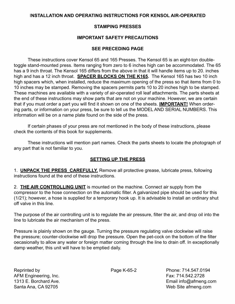
These instructions cover Kensol 65 and 165 Presses. The Kensol 65 is an eight-ton double-toggle stand-mounted press. Items ranging from zero to 6 inches high can be accommodated. The 65 has a 9 inch throat. The Kensol 165 differs from the above in that it will handle items up to 20. inches high and has a 12 inch throat. SPACER BLOCKS ON THE K165. The Kensol 165 has two 10 inch high spacers which, when installed, reduce the maximum opening of the press so that items from 0 to 10 inches may be stamped. Removing the spacers permits parts 10 to 20 inches high to be stamped. These machines are available with a variety of air-operated roll leaf attachments. The parts sheets at the end of these instructions may show parts that are not on your machine. However, we are certain that if you must order a part you will find it shown on one of the sheets. IMPORTANT! When order-ing parts, or information on your press, be sure to tell us the MODEL AND SERIAL NUMBERS. This information will be on a name plate found on the side of the press.
If certain phases of your press are not mentioned in the body of these instructions, please check the contents of this book for supplements.
These instructions will mention part names. Check the parts sheets to locate the photograph of any part that is not familiar to you.
SETTING UP THE PRESS
1. UNPACK THE PRESS_CAREFULLY. Remove all protective grease, lubricate press, following instructions found at the end of these instructions.
2. THE AIR CONTROLLING UNIT is mounted on the machine. Connect air supply from the compressor to the hose connection on the automatic filter. A galvanized pipe should be used for this (1/21); however, a hose is supplied for a temporary hook up. It is advisable to install an ordinary shut off valve in this line.
The purpose of the air controlling unit is to regulate the air pressure, filter the air, and drop oil into the line to lubricate the air mechanism of the press.
Pressure is plainly shown on the gauge. Turning the pressure regulating valve clockwise will raise the pressure; counter-clockwise will drop the pressure. Open the pet-cock on the bottom of the filter oecasionally to allow any water or foreign matter coming through the line to drain off. In exceptionally damp weather, this unit will have to be emptied daily.

Reprinted by Page K-65-3 Phone: 714.547.0194AFM Engineering, Inc. Fax: 714.542.27281313 E. Borchard Ave. Email [email protected] Ana, CA 92705 Web Site afmeng.com
NOTE: If you notice a great deal of-water collecting, your compressor tank should be drained and an after-cooler, and/or chemical type dryer installed in your main air line.
The screw or knob on the top of the automatic oiler will regulate the amount of oil going into the air line. On examining the oiler closely, you will notice a small brass nozzle inside a glass tube directly under the screw. A drop of oil forms on the end of this nozzle and falls off into the air line at regular intervals. About one drop of oil falling every 20 strokes is an ideal setting.
3. ELLECTRTAL CONNECTIONS The Press has two separate power line cords - one for the 115 Volt A.C. 50/60 cycles timing circuit and one for the heating circuit (115 Volts A.C. for a total heating system wattage of 1600 watts or less and 220 volts A.C. for greater wattages). When requested both timing circuit and heating circuit can be furnished 220 Volts A.C. For presses with impression areas larger than the standard 10 x 15 inch, a fuse disconnect switch is mounted on the press so that an electrician can feed from a 120/240 Volt A.C. (3 wire plus ground) service to a single point.WARNING NOTE: When the press is being set-up, the line coard from thetimer should be unpluged!
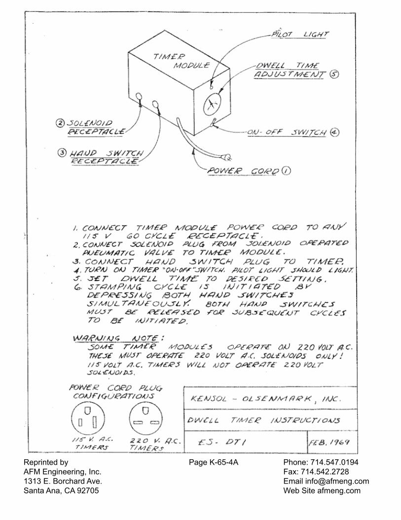
Refer to drawing ES-TD-1 in the following pages for operation of the Dwell Timer. Refer to the section titled “Set the Heat Control” for thermostat operating instructions.
OPERATION OF THE PRESS
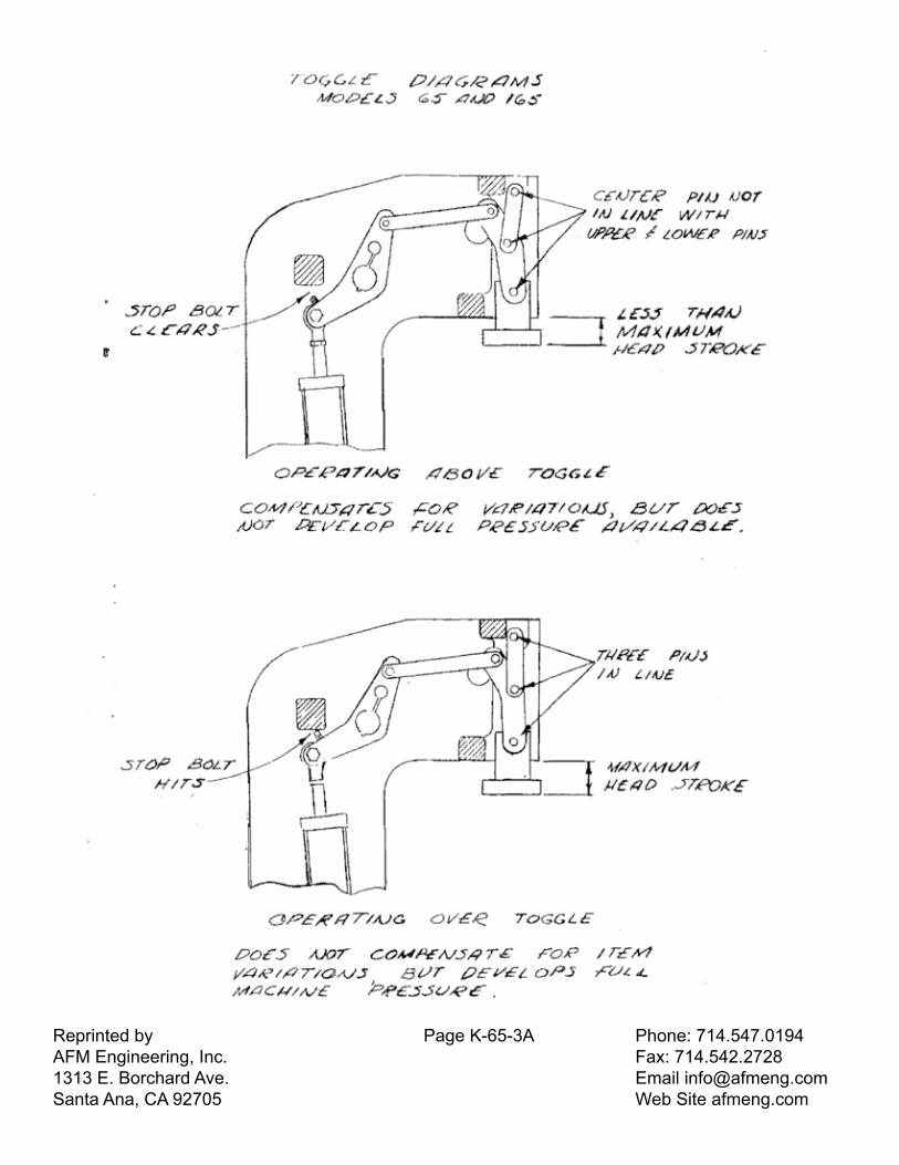
1. UNDERSTANDING THE TOGGLE ACTION (see diagram On the next page) Kensol 65 & 165 power presses are air operated with a double toggle head action to develop high pressures. The preliminary steps in setting up a job are: Locking up the type and/or dies in the head of the press (by means of the chase or pallet), setting up table guides to properly posi¬tion the work, and placing the item to be stamped in position on the work table. With everything in place, you now have to set the proper up and down position of the table. (1) The table can be set in a low position (adjusted by means of the table elevating nut) so that the stamping head makes its full stroke (toggle links straighten out and stop bolt hits main frame casting) be¬fore the die contacts the work. Setting the table in this way is called operating OVER THE CENTER OF TOGGLE. See diagram on next page.
(2) The table is raised so that the stamping head is prevented from making a full stroke (toggle links DO NOT straighten out and stop bolt does NOT hit main frame casting) when the die contacts the work. Setting the table in this way is called operating ABOVE THE CENTER OF TOG-GLE. See diagram.
When the toggle links straighten out and you are operating OVER the center of toggle, the press de-velops maximum power and the head always
Reprinted by Page K-65-3A Phone: 714.547.0194AFM Engineering, Inc. Fax: 714.542.27281313 E. Borchard Ave. Email [email protected] Ana, CA 92705 Web Site afmeng.com

Reprinted by Page K-65-4 Phone: 714.547.0194AFM Engineering, Inc. Fax: 714.542.27281313 E. Borchard Ave. Email [email protected] Ana, CA 92705 Web Site afmeng.com
comes down to its set stop. This method is satisfactory if your articles DO NOT VARY IN THICK-NESS. If they DO VARY IN THICKNESS, (molded plas¬tics, leather, etc.) you must raise the table and operate ABOVE the cen¬ter of toggle. When used in this way, the head comes down to meet the piece being marked at a constant cylinder pressure. If an article runs a little thicker than the one previously stamped, the head will not come down as far as before. If thinner, the head will come down further than before. When operating above the center of the toggle, there is one important thing to remember; The HIGHER the table is raised, the LESS pressure the machine will develop on the work. The LOWER the table (without allowing the head to go over the center of toggle) the MORE pressure the machine will develop.
2. PROPER AIR PRESSURE. When the press is operated OVER the center of toggle, and exerting maximum pressure on the item, from 50 to 100 pounds is used. Never operate above 100 pounds as this puts undue strain on the press. If press is operated below 45 pounds, it will become sluggish and the dwell timing may be erratic.
3. hAND SWITCHES. Press is operated by two hand switches (unless furnished with foot or single hand switch). When depressed together, switches complete an electrical circuit causing the pilot valve in the cylinder assembly to operate. This in turn, operates the four way valve, allowing air to come into the bottom of the main cylinder, forcing the piston up and the head of the press down. Note that as soon as the switches are depressed, the timer starts its cycle.
As soon as the preset time interval is completed, the timer breaks the circuit, and the stamping head returns to its up position.
IMPORTANT! REFER TO SAFETY PRECAUTIONS ON PAGE 1 BEFORE PROCEEDING. DRAW-INGS ON THE FOLLOWING PAGES WILL MAKE STEPS 4 AND 5 EASIER TO COMPREHEND.
4. THE ELECTRICAL DWELL TIMER has an adjusting knob. To change dwell time, move the knob until pointer is at the desired setting. SEE Sheet ES-DT1 for Dwell Timer instructions.
5. DOWN STROKE SPEED VALVE. The speed of the stamping head on the down stroke is controlled by the down stroke speed valve. Turning this clock-wise will cause the head to go down more slowly. This adjustment is useful to prevent cracking when stamping brittle materials, to lengthen the life of soft metal type and dies, to give a squeeze rather than snappy impression and other special applica-tions. Although the head comes down more slowly when the valve is turned in, the head pressure builds up to the air setting on the gauge. If you slow down the speed of the stamping head with this valve, you will have to set for a longer dwell time to compensate for the slower head action.
6.UPSTROKE SPEED VALVE. Peeling the roll leaf carrier strip off the item being stamped is ac-complished on the up-stroke of the stamping head, and is called “stripping action”. Stripping action is controlled by the
Reprinted by Page K-65-4A Phone: 714.547.0194AFM Engineering, Inc. Fax: 714.542.27281313 E. Borchard Ave. Email [email protected] Ana, CA 92705 Web Site afmeng.com
Reprinted by Page K-65-5 Phone: 714.547.0194AFM Engineering, Inc. Fax: 714.542.27281313 E. Borchard Ave. Email [email protected] Ana, CA 92705 Web Site afmeng.com
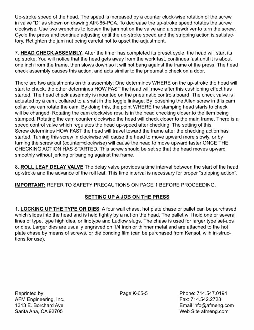
Up-stroke speed of the head. The speed is increased by a counter clock-wise rotation of the screw in valve “D” as shown on drawing AIR-65-PCA. To decrease the up-stroke speed rotates the screw clockwise. Use two wrenches to loosen the jam nut on the valve and a screwdriver to turn the screw. Cycle the press and continue adjusting until the up-stroke speed and the stripping action is satisfac-tory. Retighten the jam nut being careful not to upset the adjustment.
7. HEAD CHECK ASSEMBLY. After the timer has completed its preset cycle, the head will start its up stroke. You will notice that the head gets away from the work fast, continues fast until it is about one inch from the frame, then slows down so it will not bang against the frame of the press. The head check assembly causes this action, and acts similar to the pneumatic check on a door.
There are two adjustments on this assembly: One determines WHERE on the up-stroke the head will start to check, the other determines HOW FAST the head will move after this cushioning effect has started. The head check assembly is mounted on the pneumatic controls board. The check valve is actuated by a cam, collared to a shaft in the toggle linkage. By loosening the Allen screw in this cam collar, we can rotate the cam. By doing this, the point WHERE the stamping head starts to check will be changed. Rotating the cam clockwise results in the head checking closer to the item being stamped. Rotating the cam counter clockwise the head will check closer to the main frame. There is a speed control valve which regulates the head up-speed after checking. The setting of thisScrew determines HOW FAST the head will travel toward the frame after the checking action has started. Turning this screw in clockwise will cause the head to move upward more slowly, or by turning the screw out (counter¬clockwise) will cause the head to move upward faster ONCE THE CHECKING ACTION HAS STARTED. This screw should be set so that the head moves upward smoothly without jerking or banging against the frame.
8. ROLL LEAF DELAY VALVE The delay valve provides a time interval between the start of the head up-stroke and the advance of the roll leaf. This time interval is necessary for proper “stripping action”.
IMPORTANT: REFER TO SAFETY PRECAUTIONS ON PAGE 1 BEFORE PROCEEDING.
SETTING UP A JOB ON THE PRESS
1. LOCKING UP THE TYPE OR DIES. A four wall chase, hot plate chase or pallet can be purchased which slides into the head and is held tightly by a nut on the head. The pallet will hold one or several lines of type, type high dies, or linotype and Ludlow slugs. The chase is used for larger type set-ups or dies. Larger dies are usually engraved on 1/4 inch or thinner metal and are attached to the hot plate chase by means of screws, or die bonding film (can be purchased from Kensol, wiih in-struc-tions for use).

Reprinted by Page K-65-6 Phone: 714.547.0194AFM Engineering, Inc. Fax: 714.542.27281313 E. Borchard Ave. Email [email protected] Ana, CA 92705 Web Site afmeng.com
2. PROPER ROLL LEAF. This is very important. Roll Leaf is made in pure gold, silver (aluminum), and all popular colors. Colors are available which will print with a flat, gloss, or metallic finish. A sizing makes the roll leaf adhere to whatever material you are stamping. It is im¬portant the roll leaf supplier know the material you intend to stamp. We will gladly supply you with the desired color, sizing, and tell you the proper temperature to set your machine at.
3. SET THE ROLL LEAF ON THE SPINDLE. The roll leaf should be a little wider than the die or type (1/2 inch is recommended). Remove disc and collar from shaft and put the roll leaf between aluminum discs so that the dull (coated) side will be facing the work. When the leaf is in place, bring the leaf under the two stripper bars, up and over the knurled aluminum roller and then between the aluminum and rubber roller. These rollers are spread by means of two levers found at the end of the rubber roller. Shift the roll leaf until it is directly under the type or die. Screw down the disc collars allow-ing enough tension on the spring to keep the leaf taut as it moves through the attachment. Too little tension causes the leaf to sag. Too much tension causes it to tear. Adjust the stripper bars by means of the nuts so that these bars will keep the roll leaf about 1/4 inch from the hot die or type. It is very important that the stripper bars are kept parallel to the work table. If not parallel, the leaf will tend to crawl from one side to the other. Small guides are attached to the stripper bars. These are only used when stamping with narrow leaf to keep the leaf from shifting.
4. SETTING THE ROLL LEAF ATTACHMENT. The length of roll leaf drawn on each stroke is ad-justed by setting the stop to the appropriate position. Loosen the bolt on top of the stop and slide the stop to the end at which the pneumatic cylinder is located. (With the stop locked in this posi¬tion the roll leaf will not feed). Using the graduated scale as a guide, move the stop to the position on the scale which equals the width of impression plus about 1/16 of an inch. Lock the stop in this position by tightening the bolt. Adjust again after running if necessary to obtain a minimum space between impressions on the Roll Leaf.
The speed of the roll leaf cylinder travel is adjusted with the two needle valves as shown in the pneu-matic control assembly diagram, AIR-65-PGA. One valve controls each direction. The delay valve ad-justment controls the length of the time interval after the head starts up and before the roll leaf starts to pull. Refer to Operation of The Press, 8, Roll Leaf Delay Valve on a previous page.
5. SET THE HEAT CONTRQL. A Robertshaw degree calibrated thermostat is standard. The pointer is set to the desired temperature. You will notice that the pilot light glows, indicating that full current is flowing through the heaters. When the proper heat is reached, the light will go out and current is cut off to the heaters. While running, the light will keep going on and off indicating that the thermostat is maintaining the desired temperature level.
NOTE: With some equipment the temperature controller supplied is not the standard Robertshaw. The instructions for these special units are furnished separately.
Reprinted by Page K-65-7 Phone: 714.547.0194AFM Engineering, Inc. Fax: 714.542.27281313 E. Borchard Ave. Email [email protected] Ana, CA 92705 Web Site afmeng.com
Pure gold requires a temperature of approximately 200 degeees farenheit, while imitation gold and colors require temperatures from 225 to 300 degrees. Your leaf supplier will gladly tell you the proper heat setting for your particular leaf.
In general, if the die or type is too hot the detail will fill in and run together. When too cold, the impres-sion will be grainy due to in complete release of material. Speed and dwell must be considered along with temperature when stamping. Fast snappy impressions require higher temperature than long, lingering ones.
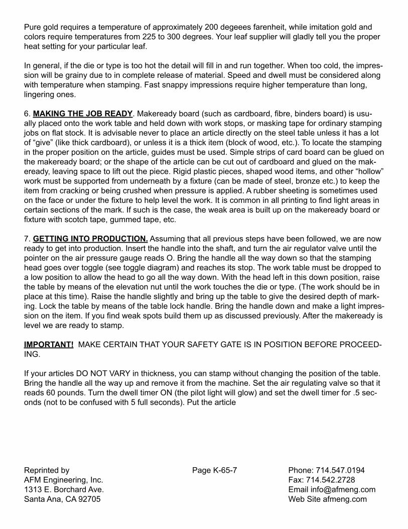
6. MAKING THE JOB READY. Makeready board (such as cardboard, fibre, binders board) is usu-ally placed onto the work table and held down with work stops, or masking tape for ordinary stamping jobs on flat stock. It is advisable never to place an article directly on the steel table unless it has a lot of “give” (like thick cardboard), or unless it is a thick item (block of wood, etc.). To locate the stamping in the proper position on the article, guides must be used. Simple strips of card board can be glued on the makeready board; or the shape of the article can be cut out of cardboard and glued on the mak-eready, leaving space to lift out the piece. Rigid plastic pieces, shaped wood items, and other “hollow” work must be supported from underneath by a fixture (can be made of steel, bronze etc.) to keep the item from cracking or being crushed when pressure is applied. A rubber sheeting is sometimes used on the face or under the fixture to help level the work. It is common in all printing to find light areas in certain sections of the mark. If such is the case, the weak area is built up on the makeready board or fixture with scotch tape, gummed tape, etc.
7. GETTING INTO PRODUCTION. Assuming that all previous steps have been followed, we are now ready to get into production. Insert the handle into the shaft, and turn the air regulator valve until the pointer on the air pressure gauge reads O. Bring the handle all the way down so that the stamping head goes over toggle (see toggle diagram) and reaches its stop. The work table must be dropped to a low position to allow the head to go all the way down. With the head left in this down position, raise the table by means of the elevation nut until the work touches the die or type. (The work should be in place at this time). Raise the handle slightly and bring up the table to give the desired depth of mark-ing. Lock the table by means of the table lock handle. Bring the handle down and make a light impres-sion on the item. If you find weak spots build them up as discussed previously. After the makeready is level we are ready to stamp.
IMPORTANT! MAKE CERTAIN THAT YOUR SAFETY GATE IS IN POSITION BEFORE PROCEED-ING.
If your articles DO NOT VARY in thickness, you can stamp without changing the position of the table. Bring the handle all the way up and remove it from the machine. Set the air regulating valve so that it reads 60 pounds. Turn the dwell timer ON (the pilot light will glow) and set the dwell timer for .5 sec-onds (not to be confused with 5 full seconds). Put the article

Reprinted by Page K-65-8 Phone: 714.547.0194AFM Engineering, Inc. Fax: 714.542.27281313 E. Borchard Ave. Email [email protected] Ana, CA 92705 Web Site afmeng.com
in place on the feed table and operate the hand (or foot) switches. Adjust the height of the work table to give the desired depth of stamping. If machine refuses to lock over toggle and you can not get the desired depth, you can raise the pressure as high as 100 pounds, or the dwell time can be changed to a longer setting. Once the desired depth is reached, vary the dwell time (and heat, if necessary) to give the finest results. You are now operating OVER THE TOGGLE. If your articles DO VARY in thickness, set the table height as explained above, remove handle, set air pressure for 60 pounds, turn timer on, and set timer dial .2 seconds (not to be confused with 2 full seconds). Unlock table lock handle and raise table two full turns. On triggering the handles, you will note that the head will not make a full stroke to meet the piece. Gradually increase the setting on the dwell-timer until the stamp-ing die or type contacts the article to be marked.
NOTE: If the head comes down too fast, so that the die or type “slaps” against the piece to be marked, then turn in the down-stroke speed valve and slow the head on the way down.
You are now operating ABOVE THE TOGGLE. Check the marking on the item. If it is not deep enough and more pressure must be applied, drop the table 1/2 a turn and try another impression (also give press a little more dwell-time). Keep dropping the table and increasing the dwell time until you have a satisfactory mark. You may find that on certain large jobs or hard materials, you may have to drop the table so far that a further drop will cause the head to go over the toggle. If such is the case, do not drop the table further, increase the pressure by turning the pressure regulating screw.
NOTE: The electrical dwell-timer not only times the dwell time, but also times the amount of time it takes for the head to travel from the up position to stamping position. Whenever you raise or lower the table to obtain different pressures, you are changing the length of stroke of the stamping head, and must alter the dwell-time setting accordingly. This rule also applies if you change the down stroke speed of the stamping head.
Reprinted by Page K-65-9 Phone: 714.547.0194AFM Engineering, Inc. Fax: 714.542.27281313 E. Borchard Ave. Email [email protected] Ana, CA 92705 Web Site afmeng.com
IMPORTANT LUBRICATION INSTRUCTIONS
Good results can not be assured unless the press is operated and lubricated properly.
There are three types of lubricant required for Kensol Power Presses. 1. SAE #10 OIL WITHOUT DETERGENT OR PENETRATING ADDITIVES 2. SAE #30 OIL 3. OLSENMARK HIGH TEMPERATURE LUBRICANT
1. Fill the automatic oiler with the Special #10 oil. (Oil that contains detergent or penetrating additives will attack packings causing valves to bind, and resulting in erratic time cycles). Adjust flow of oil as ex¬plained on sheet # 1. In normal operation this oiler will have to be filled ONCE A WEEK.
2. Using an oil can filled with SAE #30 oil, lubricate the following parts EVERY DAY:
Roll Leaf Attachment gears and other parts with oil holes.
3. Using a Grease gun, lubricate the toggle linkages and ram with OLSEN-MARK LUBRICANT. (A can was included with your machine). Be sure to lubricate these parts EVERY DAY. There are 6 grease fittings filled from the front and 11 fittings accessible from the top and back of press.
COMPRESSED AIR REQUIREMENTS
For 100 psi air, a 2 Horse Power Compressor is recommended for 1000 impressions per hour.
For other pressures and impression rates the compressor motor may be sized accordingly.
Piping air to one press (within 30 feet) - use 1/2 inch pipe (not hose). Piping air to two presses (within 30 feet) - use 3/4 inch pipe.
Piping air to more than two presses (within 30 feet) - use 1 inch pipe.
IMPORTANT! Should you notice that your press is operating abnormally, immediately turn off the heat and dwell timer. Have your maintenance department locate the source of trouble by running thru the trouble shooting instructions on the following pages or contact us.
KENSOL-OLSENMARK, INC.
40 Melville Park Road Phone 516-694-7773Melville, Long Island, New York 11746 212-762-1040
Reprinted by Page T-1 Phone: 714.547.0194AFM Engineering, Inc. Fax: 714.542.27281313 E. Borchard Ave. Email [email protected] Ana, CA 92705 Web Site afmeng.com
GENERAL TROUBLE SHOOTING PROCEDURES FOR KENSOL-STAMPING EQUIPMENT
The Kensol Press was carefully manufactured with high quality materials and components. However, over the long life of this equipment something may go out of order. Whether the hand-operated or air-operated press, the solution to the problem should be found in these instructions.
Experience shows that the primary cause of equipment failure is poor maintenance. Equipment should be properly lubricated every day (see Lubrication Instructions in section preceeding).
In general, equipment failure can be broken down into two categories:
(1) Mechanical failure in parts of the press other than air and electrical components.
(2) Failure of air or electrical components.
In order to find which of the two categories are causing the trouble on an air machine, disconnect the air line, insert the handle and operate the press manually. Make certain that the press is heated to 300 Degree. If the head moves freely with little effort on the handle, assume that there is no bind in the ram, mechanical roll leaf attachment and linkage system (toggle machines only). If the press has a mechanical pull leaf fed (rather than air pull), make certain the leaf feed is set for maximum pull. If it binds, the trouble is of a mechanical nature and not with the air components.
LOCATING A MECHANICAL FAILURE
15, 15T, 16, 17T, 18T, 25, 25T, 27T & 29T Presses:
(1) Disconnect mechanical roll leaf feed by moving setting for leaf pull to the bottom of the slide. If the press now operates smoothly by hand, there is a bind in the roll leaf attachment. Remove knob at end of knurled roller and disassemble advance mechanism. Examine for broken parts. The rubber roller should turn freely when the rollers are separated by the cams. If the rubber roller does not rotate freely the bearings are binding.
(2) If press binds with mechanical roll leaf disconnected, the bind must be in the ram. The gibs should be readjusted to allow a smooth sliding action yet maintaining as little play in the ram as possible.
Reprinted by Page T-2 Phone: 714.547.0194AFM Engineering, Inc. Fax: 714.542.27281313 E. Borchard Ave. Email [email protected] Ana, CA 92705 Web Site afmeng.com
36, 36T, 50, 60., 110, 65 & 165 Presses:
(1) Run thru step #1 on precaeding page.
(2) If press binds with roll leaf disconnected, the bind could be in the ram, links, pins, or main shaft.
LINKS & PINS - The links should move freely on the pins. These can be checked by tapping the links or pins from the side with a mallet. The links should shift slightly side to side. If not, free the particular link and pin assembly.
RAM - If the press still binds after having eliminated the links and pins and the rein leaf attachment as a source of trouble, the ram is binding. The fit of the ram is adjusted by loosening the four large bolts found on the ram cap and adjusting the four set screws (found by each bolt) as follows:
Make certain the roll leaf attachment is disengaged. This will give a better opportunity to judge the sliding fit of the ram. This fit should be free but-not sloppy. If sloppy, the head may twist a little and jam up the roll leaf mechanism. The best way to make this adjustment is to work the handle up and down while tightening and loosening the four bolts. Loosen only one bolt at a timer and retighten it before going to the next bolt if it does not lessen the bind. If one particular bolt; when lobsened, frees the ram, turn in the Corresponding set screw. The bolt can then be tightened. In some cases, it may be necessary to loosen.and reset two set screw-bolt combinations. Make sure the head is up to heat and spend some time on this-very important adjustment
LOCATING AN AIR COMPONENT FAILURE
ALL AIR PRESSES:
If it is determined after converting the press to hand operation that the air system is at fault, the trou-ble must be’ localized in one Of these components: Hand Switches, Dwell-Timer, Air Cylinder, 4-Way Valve, Pilot Valve, or Air-Controlling Unit.
Hand Switches - Check these by pulling plug that goes into timer. Using an Ohm meter, check the continuity between the prongs. This is done by operating the-hand switches while the meter probes are attached to the Male receptacle prongs.
Dwell-Timer - It is very seldom that the dwell-timer will completely fail so that the head will not come down at all. The usual symptom of a faulty timer is an erratic Cycle (one impression short, one long, etc.). However, it must be mentioned that there are “normal” inaccuracies in any timer. Slight inacu-racies on a split second cycle can be expected. If the press completely fails to operate, pull out the timer plug that connects to the main cylinder

Reprinted by Page T-3 Phone: 714.547.0194AFM Engineering, Inc. Fax: 714.542.27281313 E. Borchard Ave. Email [email protected] Ana, CA 92705 Web Site afmeng.com
assembly. Using a test light, operate the two hand switches. If the test light does not glow during the timing cycle, the timer is faulty.
Air-Cylinder, Pilot Valve, 4-Way Valve - These components are considered as one complete as-sembly in trouble shooting. If the ram action of the press is erratic and the mechanical sections of the press and the dwell timer have been eliminated as the cause of failure, the air assembly must be faulty. The complete assembly is either returned to us for repair or disassembled and examined for:
(1) Broken electrical connection in pilot valve. (This has been checked previously by applying line voltage across the two prong cable plug).
(2) Broken return spring in the four-way valve.
(3) Bind of the spindle in the four-way valve. This is usually caused by “0” ring expansion due to the use of oil containing additives.
(4) By pass of air around 4-way valve spindle or cylinder cups. Caused by the use of oil with additives (in automatic lubricator).
(5) Corrosion due to excessive water getting into the press.(6) Scoring of the walls of the cylinder.
Air Controlling Unit - The air controlling unit consists of an air filter, regulator, and lubricator. Any failure of these parts is usually apparent. The air filter is designed to remove water from the air line. If excessive water is building up so that this has to be drained a few times each day, it is advisable to have an after cooler installed on the compressor. Repair kits for these components are available through Kensol if you find that they are not functioning properly.
SYMPTOM
1. Press will not heat up at all.
2. Press will not heat up to operating temperature
3. Press overheats (light on thermostat stays on)
PROBABLE CAUSE
a. Blown fuses in electrical supplyb. Defective heater or heatersc. Loose or—broken wired. Defective thermostat
a. Defective heater or heatersto operating temperature b. One fuse blown on 220 line
a. Defective thermostat

Reprinted by Page T-4 Phone: 714.547.0194AFM Engineering, Inc. Fax: 714.542.27281313 E. Borchard Ave. Email [email protected] Ana, CA 92705 Web Site afmeng.com
SYMPTOM
4. Head will not come down
5. Head comes down and stays down
6. Head will not come all
7. Head slams on up stroke
8. Machine sluggish: both up and down
9. Blurry impression: not sharp and clear
10. Inconsistent impression some deep, some light
11. Erratic leaf pull Mechanically operated roll leaf attachment
PROBABLE CAUSE
a. Linkage frozen, (toggle machine only) Ram frozenb. 4-way valve or main cylinder jammed due to lack of lubri¬cation (Air machine only)c. No output from timerd. No air from supply or not enough pressure
a. Broken spring in 4-way valveb. Bind in 4-way valve or main cylinderc. Short in timer
a. Jam in mechanical roll leaf attachment
a. Head check assembly out of adjustment (toggle machine only)
b. Badly worn linkage system (toggle machine only)c. Bind in ram or linkage (toggle machine only)
a. Speed valves closed too farb. Air line cloggedc. Air lines too smalld. Too low air pressure
a. Head shifting due to too much play in ramb. Die or type holder not locked tightly in head
a. Too short of a dwell setting some deep, some light (never go below 0.4 seconds)b. Poor lubricationc. Erratic timerd. Fluctuating air pressuree. Defective packing in 4-way valve or main cylinder
a. Rubber roller wornb. Knurled roller slipping on its shaftc. Defective clutch (late machines)d. Loose pawls or broken springs on ratchet leafe. Roll leaf tension disc too tightf. Bushings for knurled or rubber roller worn

Reprinted by Page T-5 Phone: 714.547.0194AFM Engineering, Inc. Fax: 714.542.27281313 E. Borchard Ave. Email [email protected] Ana, CA 92705 Web Site afmeng.com
SYMPTOM
Air-operated roll -leaf attachment
12. Leaf runs off to one side when pulling
13. Air leaking out of top of main cylinder
14. Air leaking out of check valve (toggle machines only)
15. Oil leaking out of mufflers
PROBABLE CAUSE
a. Check a, b, c, e, & f aboveb. Air pull cylinder not returning all the wayc. Air pull cylinder moving too fast-adjust speed valvesd. Air pull 4-way valve defecative. Delay valve packings defective
a. Stripper bars are not levelb. Rollers are badly wornc. One side of steel or rubber roller bearing worn more than other side
a. Worn top packing in cylinderb. Retaining nut may be loose (older ma-chines)
a. By pass in cylinder or 4-way valve
a. Incorrect adjustment of automatic lubricator

Reprinted by Page T-6 Phone: 714.547.0194AFM Engineering, Inc. Fax: 714.542.27281313 E. Borchard Ave. Email [email protected] Ana, CA 92705 Web Site afmeng.com

Reprinted by Page T-7 Phone: 714.547.0194AFM Engineering, Inc. Fax: 714.542.27281313 E. Borchard Ave. Email [email protected] Ana, CA 92705 Web Site afmeng.com
PARTS SHEET FOR KENSOL EQUIPMENT - #65-A When ordering parts, supply serial number (found on plate on side of press) and year purchased whenever possible. When ordering electrical parts, be sure to tell us whether your machine is wired for 115 or 230 Volts A.C.
PART NO. PART NAME PART NO. PART NAME 65- 1 Timer Assembly (1) 65-19 Copper Tube (A.R.)65- 2 Cylinder Repair Kit (1) 65-20 Solenoid Valve (1)65- 3 Rod End Bearing (1) 65-21 Roller Salve (1)65- 4 Nut (1) 65-22 Muffler (-)65- 5 Hose Connector to 65-23 Pilot Valve (1) Cylinder (2) 65-24 Poly-Flo Tube (A.R.) Hose Connector to 65-25 FRL Unit, Complete (1) Valve (2) 65-25a Lubricator (1)65- 6 Bushing (2) 65-25b Lubricator Bowl (1)65- 7 Cylinder (1) 65-25c Filter (1)65- 8 Retaining Ring (2) 65-25d Filter Bowl (1)65- 9 Pin (1) 65-25e Regulator Gage (1)65-10 Hex Head Bolt (4) 65-25f Bracket (1)65-11 Lock Washer (4) 65-26 FRL Unit Repair Kit (1)65-12 Clevis (1) 65-27 Mounting Plate (1)65-13 Valve Repair (1) 65-28 Twist Lock Plug (1)65-14 Hose (A.R.) 65-29 Switch (4)65-15 Metering Valve (1) 65-30 Hand Switch 65-16 Delaying Valve (1) Assembly, Complete(1)65-17 Twist Lock Plug (1) 65-31 Cam (1)65-18 Speed Control Muffler(5) 65-32 Solenoid Assembly (1)

Reprinted by Page T-8 Phone: 714.547.0194AFM Engineering, Inc. Fax: 714.542.27281313 E. Borchard Ave. Email [email protected] Ana, CA 92705 Web Site afmeng.com
Reprinted by Page T-9 Phone: 714.547.0194AFM Engineering, Inc. Fax: 714.542.27281313 E. Borchard Ave. Email [email protected] Ana, CA 92705 Web Site afmeng.com
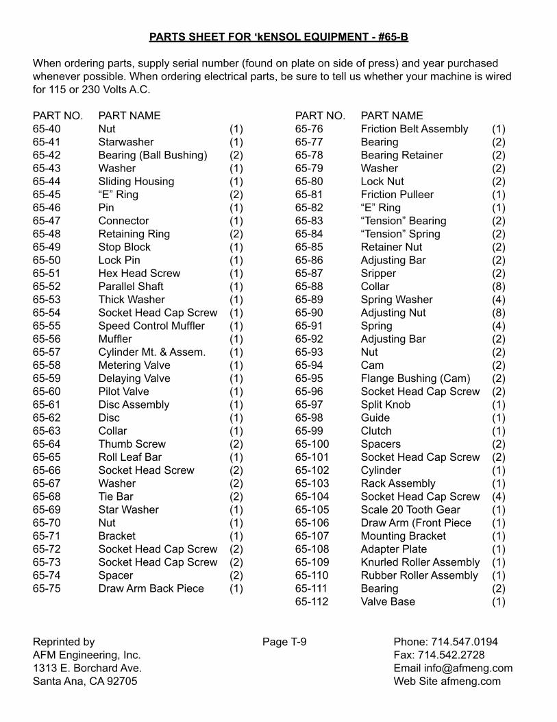
PARTS SHEET FOR ‘kENSOL EQUIPMENT - #65-B When ordering parts, supply serial number (found on plate on side of press) and year purchased whenever possible. When ordering electrical parts, be sure to tell us whether your machine is wired for 115 or 230 Volts A.C. PART NO. PART NAME PART NO. PART NAME65-40 Nut (1) 65-76 Friction Belt Assembly (1) 65-41 Starwasher (1) 65-77 Bearing (2)65-42 Bearing (Ball Bushing) (2) 65-78 Bearing Retainer (2)65-43 Washer (1) 65-79 Washer (2)65-44 Sliding Housing (1) 65-80 Lock Nut (2)65-45 “E” Ring (2) 65-81 Friction Pulleer (1)65-46 Pin (1) 65-82 “E” Ring (1)65-47 Connector (1) 65-83 “Tension” Bearing (2)65-48 Retaining Ring (2) 65-84 “Tension” Spring (2)65-49 Stop Block (1) 65-85 Retainer Nut (2)65-50 Lock Pin (1) 65-86 Adjusting Bar (2) 65-51 Hex Head Screw (1) 65-87 Sripper (2)65-52 Parallel Shaft (1) 65-88 Collar (8)65-53 Thick Washer (1) 65-89 Spring Washer (4)65-54 Socket Head Cap Screw (1) 65-90 Adjusting Nut (8)65-55 Speed Control Muffler (1) 65-91 Spring (4)65-56 Muffler (1) 65-92 Adjusting Bar (2)65-57 Cylinder Mt. & Assem. (1) 65-93 Nut (2)65-58 Metering Valve (1) 65-94 Cam (2)65-59 Delaying Valve (1) 65-95 Flange Bushing (Cam) (2)65-60 Pilot Valve (1) 65-96 Socket Head Cap Screw (2)65-61 Disc Assembly (1) 65-97 Split Knob (1)65-62 Disc (1) 65-98 Guide (1)65-63 Collar (1) 65-99 Clutch (1)65-64 Thumb Screw (2) 65-100 Spacers (2)65-65 Roll Leaf Bar (1) 65-101 Socket Head Cap Screw (2)65-66 Socket Head Screw (2) 65-102 Cylinder (1)65-67 Washer (2) 65-103 Rack Assembly (1)65-68 Tie Bar (2) 65-104 Socket Head Cap Screw (4)65-69 Star Washer (1) 65-105 Scale 20 Tooth Gear (1)65-70 Nut (1) 65-106 Draw Arm (Front Piece (1)65-71 Bracket (1) 65-107 Mounting Bracket (1)65-72 Socket Head Cap Screw (2) 65-108 Adapter Plate (1)65-73 Socket Head Cap Screw (2) 65-109 Knurled Roller Assembly (1)65-74 Spacer (2) 65-110 Rubber Roller Assembly (1)65-75 Draw Arm Back Piece (1) 65-111 Bearing (2) 65-112 Valve Base (1)
Reprinted by Page T-10 Phone: 714.547.0194AFM Engineering, Inc. Fax: 714.542.27281313 E. Borchard Ave. Email [email protected] Ana, CA 92705 Web Site afmeng.com

Reprinted by Page T-11 Phone: 714.547.0194AFM Engineering, Inc. Fax: 714.542.27281313 E. Borchard Ave. Email [email protected] Ana, CA 92705 Web Site afmeng.com
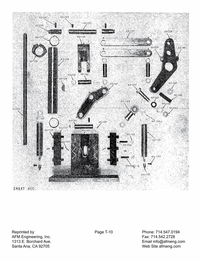
PARTS SHEET FOR KENSOL EQUIPMENT - #65-C
When ordering parts, supply serial number (found on plate on side of press) and year purchased whenever possible. When ordering electrical parts, be sure to tell us whether your machine is wired for 115 or 230 Volts A.C.
PART NO. PART NAME. PART NO. PART NAME 65-125 Handle (1) 65-143 Hex. Head Screw (1)65-126 Cam (1) 65-144 Washer (1)65-127 Retaining Ring (2) 65-145 Nut (2)65-128 Main Shaft (1) 65-146 Socket Set Screw (1)65-129 Woodruff Key (1) 65-147 Nut (1)65-130 Pin, Spring (2) 65-148 Rod End Bearing (1)65-131 Socket Set Screw (3) 65-149 Grease Fitting (14)65-132 Socket Set Screw (1) 65-150 Spring Eye (2)65-133 Pin (1) 65-151 Main Spring (2)65-134 Dual Link (1) 65-152 Socket Head Screw (2)65-135 Retaining Ring (6) 65-153 Spring Mount (2)65-136 Pin (3) 65-154 Socket Head Screw (2)65-137 Link (2) 65-155 Jam Nut (2)65-138 Large Toggle Arm (1) 65-156 Gib-Head Ram (Right) (1)65-139 Nut (1) 65-157 Gib-Head Ram (Left) (1) 65-140 Hex. Head Bolt 65-158 Socket Head Screw (6) Head Treated (1) 65-159 Roll Pin (2) 65-141 Small Toggle Arm (1) 65-160 Ram Assembly (1)65-142 Hex. Head Screw (1) 65-161 Pin (1)
Reprinted by Page T-12 Phone: 714.547.0194AFM Engineering, Inc. Fax: 714.542.27281313 E. Borchard Ave. Email [email protected] Ana, CA 92705 Web Site afmeng.com
Reprinted by Page T-12 Phone: 714.547.0194AFM Engineering, Inc. Fax: 714.542.27281313 E. Borchard Ave. Email [email protected] Ana, CA 92705 Web Site afmeng.com
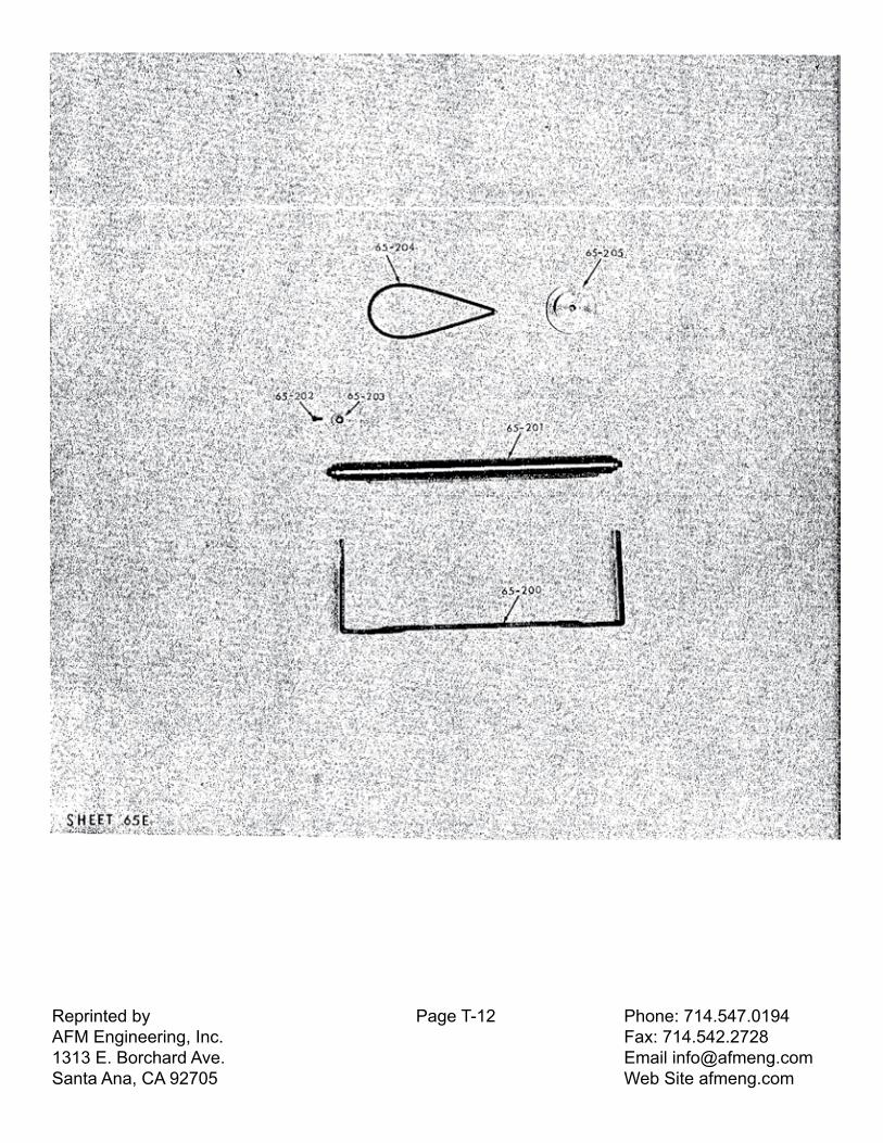
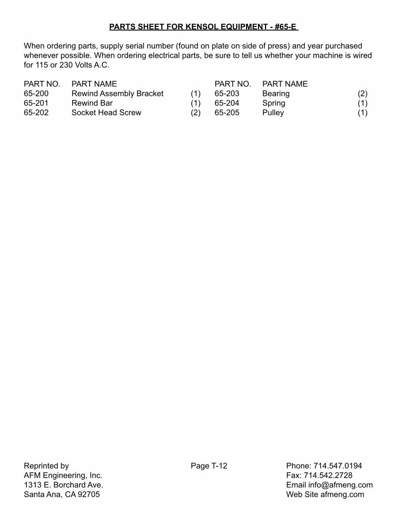
PARTS SHEET FOR KENSOL EQUIPMENT - #65-E
When ordering parts, supply serial number (found on plate on side of press) and year purchased whenever possible. When ordering electrical parts, be sure to tell us whether your machine is wired for 115 or 230 Volts A.C.
PART NO. PART NAME PART NO. PART NAME 65-200 Rewind Assembly Bracket (1) 65-203 Bearing (2)65-201 Rewind Bar (1) 65-204 Spring (1)65-202 Socket Head Screw (2) 65-205 Pulley (1)

Reprinted by Page T-13 Phone: 714.547.0194AFM Engineering, Inc. Fax: 714.542.27281313 E. Borchard Ave. Email [email protected] Ana, CA 92705 Web Site afmeng.com
Reprinted by Page T-13 Phone: 714.547.0194AFM Engineering, Inc. Fax: 714.542.27281313 E. Borchard Ave. Email [email protected] Ana, CA 92705 Web Site afmeng.com
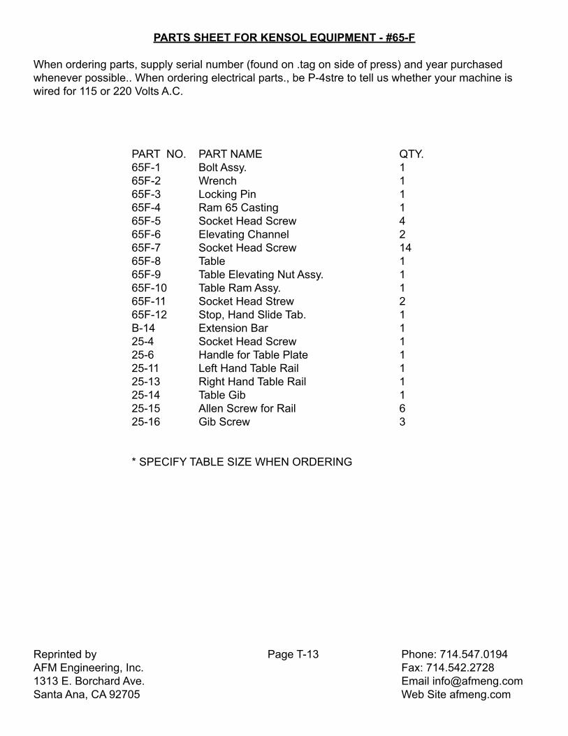
PARTS SHEET FOR KENSOL EQUIPMENT - #65-F
When ordering parts, supply serial number (found on .tag on side of press) and year purchased whenever possible.. When ordering electrical parts., be P-4stre to tell us whether your machine is wired for 115 or 220 Volts A.C.
PART NO. PART NAME QTY.65F-1 Bolt Assy. 165F-2 Wrench 165F-3 Locking Pin 165F-4 Ram 65 Casting 165F-5 Socket Head Screw 465F-6 Elevating Channel 265F-7 Socket Head Screw 1465F-8 Table 165F-9 Table Elevating Nut Assy. 165F-10 Table Ram Assy. 165F-11 Socket Head Strew 265F-12 Stop, Hand Slide Tab. 1B-14 Extension Bar 125-4 Socket Head Screw 125-6 Handle for Table Plate 125-11 Left Hand Table Rail 125-13 Right Hand Table Rail 125-14 Table Gib 125-15 Allen Screw for Rail 625-16 Gib Screw 3
* SPECIFY TABLE SIZE WHEN ORDERING

Reprinted by Page T-14 Phone: 714.547.0194AFM Engineering, Inc. Fax: 714.542.27281313 E. Borchard Ave. Email [email protected] Ana, CA 92705 Web Site afmeng.com
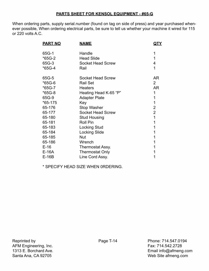
PARTS SHEET FOR KENSOL EQUIPMENT - #65-G
When ordering parts, supply serial.number (found on tag on side of press) and year purchased when-ever possible, When ordering electrical parts, be sure to tell us whether your machine it wired for 115 or 220 volts A.C.
Reprinted by Page T-14 Phone: 714.547.0194AFM Engineering, Inc. Fax: 714.542.27281313 E. Borchard Ave. Email [email protected] Ana, CA 92705 Web Site afmeng.com
PART NO NAME QTY
65G-1 Handle 1*65G-2 Head Slide 165G-3 Socket Head Screw 4*65G-4 Rail 1
65G-5 Socket Head Screw AR*65G-6 Rail Set 2*65G-7 Heaters AR*65G-8 Heating Head K-65 “P” 165G-9 Adapter Plate 1*65-175 Key 165-176 Stop Washer 265-177 Socket Head Screw 265-180 Stud Housing 165-181 Roll Pin 165-183 Locking Stud 165-184 Locking Slide 165-185 Nut 165-186 Wrench 1E-16 Thermostat Assy. 1E-16A Thermostat Only 1E-16B Line Cord Assy. 1
* SPECIFY HEAD SIZE WHEN 0RDERING.