kennametal tool application handbook
TRANSCRIPT

KfNNAMfTAl TOOL APPLICATION
HANDBOOK

,...
KENNAMfTAL TOOL
APPLICATION HANDBOOK No.9
The Ken namelal Tool Applicalion Handbook
is d esigned primarily 10 help ma chine operalOrs, 1001 layoul and 1001 main lenance men in Ihe se
leclion, applicalion, and mainlenance of Ken na
mela l lOoling 10 oblain maximum econ omic bene
fils. Tool en gineers and d esigners should also find
il valuable a s Ihe informalion herein is based on
dam from many years of developmenl work in ou r
research laboralOries as well as experience gain ed from aClual shop operalions.
Copyright 196 7 b y Kennametal Inc., Latrobe, Pa. 1 5 6 5 0 , U.S.A. A l l rights reserved. Whenever the following names appear in this manual they are used as T r a d emarks: K e n n ametal, K e n d ex, Kenloc, K.Bar, DeVibrator, K2S, K 3 H, K4H, K5H, K6, K 2 1 , K 1 6 5, KM.
KENNAMETAL INC. LATROBE, PA. 15650, U.S.A.
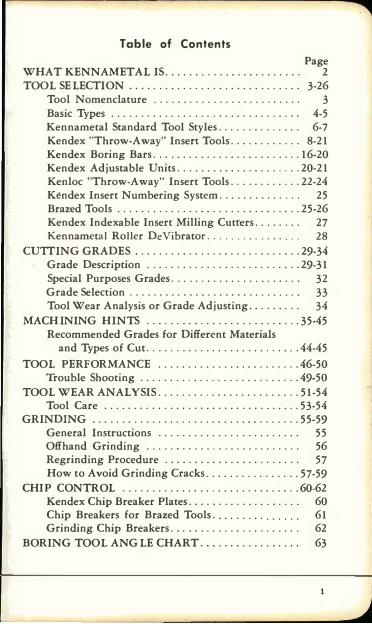
Table of Contents
Page WHAT KENNAMET AL IS....................... 2 TOOL SELECTION . . . . . . . . . . . . . . . . . . . . . . . . . . . .. 3-26
Tool Nomenclature . ........................ 3 Basic Types . . . . . . . . . . . . . . . . . . . . . . . . . . . . . . .. 4-5 Kennametal Standard Tool Styles. . . . . . . . . . . . .. 6-7 Kendex "T hrow-Away" Insert Tools ............ 8-21 Kendex Boring Bars ......................... 16-20 Kendex Adjustable Units ..................... 20-21 Kenloc "T hrow-Away" Insert Tools ............ 22-24 Kendex Insert Numbering System. . . . . . . . . . . . . . 25 Brazed Tools ............................... 25-26 Kendex Indexable Insert Milling Cutters. . . . . . . . 27 Kennametal Roller DeVibrator. . . . . . . . . . . . . . . . 28
CUTTING GRADES ............................ 29-34 Grade Description . . ........................ 29-31 Special Purposes Grades. . . . . . . . . . . . . . . . . . . . . . 32 Grade Selection . . . . . . . . . . . . . . . . . . . . . . . . . . . . . 33 Tool Wear Analysis or Grade Adjusting. . . . . . . . . 34
MACHINING HINTS ......... ................. 35-45 Recommended Grades for Different Materials
and Types of Cut .................... . ... . . 44-45 TOOL PERFORMANCE ........................ 46-50
Trouble Shooting ...... . . ................... 49-50 TOOL WEAR ANALYSIS ...................... .. 51-54
Tool Care ................................. 53-54 GRINDING ..................... . ......... . ... 55-59
General Instructions ........................ 55 Offhand Grinding ..... . . . ... . .............. 56 Regrinding Procedure . . . . . . . . . . . . . . . . . . . . . . . 57 How to Avoid Grinding Cracks ................ 57-59
CHIP CONT ROL .......... . ........... . ....... 60·62 Kendex Chip Breaker Plates. . . . . . . . . . . . . . . . . . . 60 Chip Breakers for Brazed Tools. . . . . . . . . . . . . . . 61 Grinding Chip Breakers. . . . . . . . . . . . . . . . . . . . . . 62
BORING TOOL ANGLE CHART . . . . . . . . . . . . . . . . . 63
WHAT KENNAMETAL 15 Kennametal is the trade-name for a series of ce
mented carbide compositions of which the essential ingredients are tungsten, tantalum, columbium, titanium, and cobalt. The original invention of WTiC2 (tungsten-titanium-carbide ) was the first commercially-successful carbide for cutting stee1. Today more than 40 different Kennametal compositions have been developed for specific applications.
Kennametal is produced by exclusive processes that give it certain desirable characteristics not otherwise obtainable. Some of these methods o f manufacture, a s well as a number o f Kennametal products, are covered by U. S. patents.
Since the discovery of the original Kennametal grade, the company has innovated many tool designs and tooling techniques, including cutters for highrate carbide milling and heavy-duty tooling for machining steel mill rolls, shell forgings, and railroad wheels and axles. Kennametal also pioneered the development of tools with mechanically-held carbide inserts such as the Kendex, Kennamatic, and heavy duty type tools. These developments have contributed to the wider use of carbide cutting tools as well as to greater machining efficiency.
2
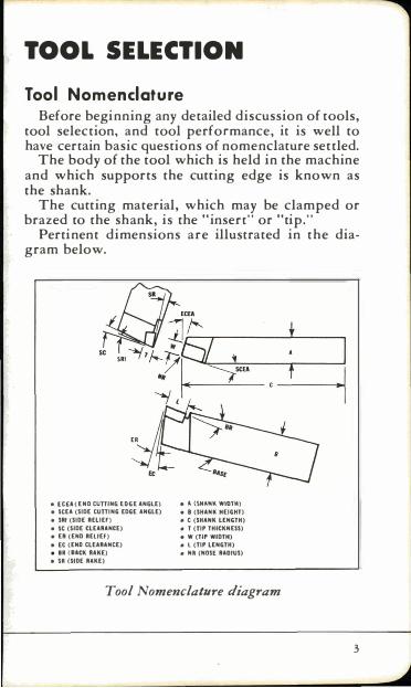
TOOL SELECTION Too l No menclature
Before beginning any detailed discussion of tools, tool selection, and tool performance, it is well to have certain basic questions of nomenclature settled.
The body of the tool which is held in the machine and which supports the cutting edge is known as the shank.
The cutting material, which may be clamped or brazed to the shank, is the "insert" or "tip."
Pertinent dimensions are illustrated in the diagram below.
• [eU (END CUTTING (OGE ANGLE) • A. {SHANK WIOTH) • seEA (SIDE CUTTING EDGE ANGLE) • B (SHANk HEIGHT)
• SRI (SIDE RELlEr) • C (SHANK LENGTH)
• Ie (SIDE CLEARANCE) • T (TIP THICKNESS)
• ER (END RELIEF) • W (TIP WIDTH)
• (t (END CLEARANCE) • L (TIP LENGTH)
• BR ( .... CK UKE) • Nft (NOS( RADIUS)
• $It (SIDE RAKE)
Tool Nomenclature diagram
3
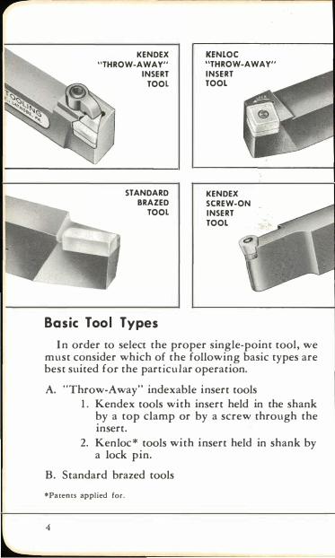
KENDEX "THROW-AWAY"
INSERT TOOL
STANDARD BRAZED
TOOL
KENLOC "THROW-AWAY" INSERT TOOL
KENDEX SCREW-ON INSERT TOOL
Basic Too l T ypes
I n order to select the proper single-point tool, we must consider which of the following basic types are best suited for the particular operation.
A. "Throw-Away" indexable insert tools 1. Kendex tools with insert held in the shank
by a top clamp or by a screw through the insert.
2. Kenloc* tools with insert held in shank by a lock pin.
B. Standard brazed tools
* Patents applied for.
4
Re place able Inse rt Too ls "Throw-Away" insert tools are the most econom
ical for practically all types of metal-cutting operations for two reasons: (1) The inserts provide a number of low-cost, indexable cutting edges. ( 2) After all edges are used, it is more economical to replace the insert than it is to regrind a brazed tool.
• Kendex top clamp tools are available in a wide range of styles and size with negative and positive rake angles for turning, facing, chamfering, threading, grooving, profiling, and boring operations. The top clamp design permits use of utility or precision inserts with or without chip breaker plates, as well as inserts with pin lock center holes.
• Small Kendex "screw-on" insert tools provide indexable inserts for jobs where design or size of holder does not permit the use of clamped insert tools. On large tools the heavy duty "screw-on" insert may be indexed "once around" and then replaced; or it may be reground a limited number of times - depending on the size of insert and operation.
• Kenloc tools for general purpose machining utilize economical inserts with preformed chip control grooves and central holes for insert locking. All inserts are negative rake type, usable on top and bottom faces to provide up to eight indexable cutting edges. Tools are available with triangular, square, round, or diamond-shaped inserts.
Brazed Tools • Standard brazed tools-which are low in initial
cost-aI'e suitable for most general purpose machining operations where maximum tool performance is of secondary importance. They can be easily modified for special purpose, short run applications.
5
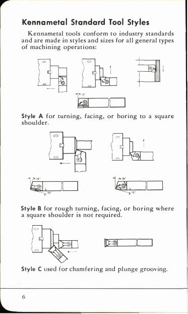
K enna meta l Standard Tool St y les Kennametal tools conform to industry standards
and are made in styles and sizes for all general types of machining operations:
Style A for turning, facing, or boring to a square shoulder.
Style B for rough turning, facing, or boring where a square shoulder is not required.
Style C used for chamfering and plunge grooving.
6
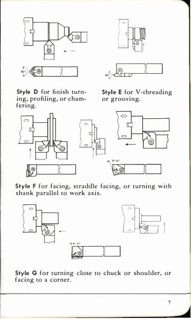
Style 0 for finish turning, profiling, or chamfering.
.o� )D
Style E for V -threading or grooving.
10 Style F for facing, straddle facing, or turning with shank parallel to work axis.
�I
Style G for turning close to chuck or shoulder, or facing to a corner.
7
Kendex "Throw -Awa y " Insert Too ls
Kendex "throw-away" insert tools bring the economical advantages of indexable, mechanically-held cutting edges to tools with shanks as small as 3/8-inch square. They use flat multiple-edge inserts in triangular, square, round and diamond shapes. Inserts are clamped in heat-treated holders at negative, positive or neutral rake angles.
Kendex negative rake tools permit inserts to be turned over, thus doubling the number of cutting edges available. Inserts used with positive rake tools are indexable but cutting edges are provided on one face only.
Kendex tools are available in many styles and sizes for practically every type of machining operation.
Kendex Too l Features
• "Throw-away" inserts el iminate regrinding
Cost records show that on most jobs it is more economical to replace either positive or negative rake Kendex inserts, after all edges have been used, than it is to regrind a brazed tool.
• Universal Chip Control
8
Effective chip control over a wide range of applications is provided by two methods: 1. Chipbreaker plates (of solid Kennametal ) have
exceptional strength and resistance to "pickup". Adjustment for best chip control can be obtained by using different sizes of chipbreaker plates.
2. Kenloc inserts with preformed chip grooves provide constant chip control over a wide range of feeds on general machining operations.
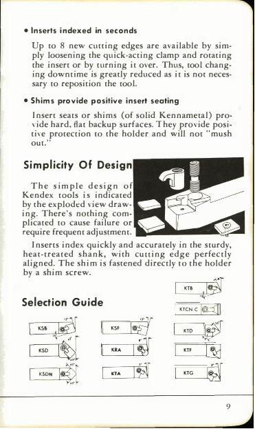
• Inserts i ndexed in seconds
Up to 8 new cutting edges are available by simply loosening the quick-acting clamp and rotating the insert or by turning it over. Thus, tool changing downtime is greatly reduced as it is not necessary to reposition the tool.
• Sh ims provide positive insert seating
I nsert seats or shims (of solid Kennametal) provide hard, fiat backup surfaces. They provide positive protection [0 the holder and will not "mush our."
Si mplicit y Of Design
The s imple design o f Kendex [Ools i s indicated by the exploded view drawing. There's nothing complicated [0 cause failure or require frequent adjustment . • �"'.IIiI •••
Inserts index quickly and accurately in the sturdy, heat-treated shank, with cuuing edge perfectly aligned. The shim is fastened directly [0 the holder by a shim screw.
Selection Gu ide
L-K_S_f ---,1!iJ iJ'·1 r----.--I KRA
.
KSON 1#3 lOA
� I KTS ,t I KTCN.C l¢::?1i
KTD �"T I� KTF IiLJ ��
,--K_TG_-,I� 9
,... Suggestions For Selecting Kendex Tools A. Rake Angles
1. Vse Negative Rake Tools: • For general purpose machining of most mate
rials-especially rough or interrupted Cuts. • For hard materials on rigid setups. • For greatest economy as inserts can be
turned over.
2. Vse Positive Rake Tools: • For machining softer steels and nonferrous
metals. • For gummy, work-hardening alloys. • For slender parts or thin wall tubing which
will not stand high cutting forces. • On low powered machines or setups which
lack rigidity.
B. Selecting Tool Holders
1. Determine the proper tool style for the job. 2. Select an insert with adequate cutting edge
length. 3. Choose the largest shank possible.
C. Selecting Inserts
1 0
1. Vtility or Precision • Utility inserts have top and bottom ground
for rough machining. • Precision inserts have all surfaces ground
for general rough and finish machining. • Kenlock inserts with preformed chip control
grooves can be used in all Kendex tools.
-
2. Shapes • Square Inserts: H ave strong structural shape
(900 point angle )-Used in lead angle and chamfering tools.
• Triangular Inserts: Have 600 point angleUsed for cutting to square shoulder, for profiling, chamfering, or plunge turning.
• Round Inserts: Provide shallow feed marks at high feed rates on finishing passes. -Inherent durable shape is ideal for heavy
roughing cuts. -Particularly suitable for cutting cast iron .
• Diamond Inserts: 800 nose angle type used for combination turning and facing toolsI nserts with 550 nose angle are used in profiling tools .
• Rectangular Inserts: For heavy duty Kendex tools on cuts greater than 1/2-inch in depth.
• Threading and grooving inserts.
3. Radius • Use smal l rad ius for steel and materials
which cut with a continuous chip. • Use larger radius for cast iron.
4. G,'ade Selection • See pages 29 through 34.
D. Chip Breakers
Chip breaker plates in various widths are available to match the size and shape of insert. See pages 60 and 61. Kenloc inserts with preformed chip grooves are available for general machining operations. The preformed chip grooves provide chip control over a wide range of feeds and speeds.
1 1
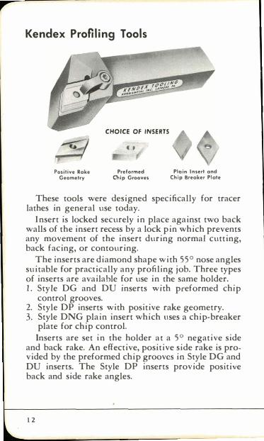
Kendex Profiling Tools
CHOICE OF INSERTS
11 4'
Positive Rake Geometry
Preformed Chip Grooves
PICJin Insert and Chip Breaker Plate
These tools were designed specifically for tracer lathes in general use today.
Insert is locked securely in place against two back walls of the insert recess by a lock pin which prevents any movement of the insert during normal cutting, back facing, or contouring.
The inserts are diamond shape with 55° nose angles suitable for practically any profiling job. Three types of inserts are available for use in the same holder. 1. Style DG and DU inserts with preformed chip
control grooves. 2. Style DP inserts with positive rake geometry. 3. Style DNG plain insert which llses a chip-breaker
plate for chip control. Inserts are set in the holder at a 5° negative side
and back rake. An effective, positive side rake is provided by the preformed chip grooves in Style DG and DU inserts. The Style DP inserts provide positive back and side rake angles.
1 2
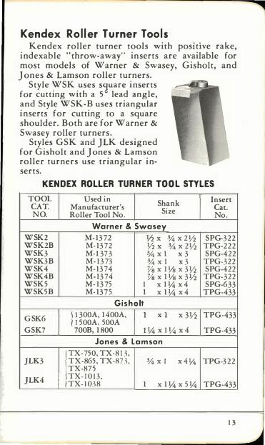
Kendex Ro ller Turner Tools Kendex roller turner tools with posItive rake,
indexable "throw-away" inserts are available for most models of Warner & Swasey, Gisholt, and Jones & Lamson roller turners.
Style WSK uses s�uare inserts for cutting with a 5 lead angle, and Style WSK-B uses triangular inserts for cutting to a square shoulder. Both are for Warner & Swasey roller turners.
Styles GSK and JLK designed for Gisholt and Jones & Lamson roller turners use triangular inserts.
KENDEX ROLLER TURNER TOOL STYLES TOOL Used in
Shank Insert CAT. Manufacturer's Cat. NO. Roller Tool No. Size
No.
Warner & Swasey
WSK2 M-1372 Y2x % x2Y2 SPG-322 WS K2B M-1372 Y2x % x2Y2 TPG-222 WS K 3 M-1 37 3 3A x 1 x 3 SPG-422 WS K3B M-1373 % x 1 x3 TPG-322 WSK4 M-1374 Ys x Ills x 3Y2 SPG·422 WSK4B M-1374 Ys x Ills x 3Y2 TPG·322 WS K 5 M-1375 I x 1� x4 SPG-633 WS K 5 B M-137 5 1 x 1� x4 TPG-433
Gisholt
GSK6 51 300A,1400A, ( 1 500A, 500A
I xl x 3Y2 TPG-433
GS K7 700B,1800 l�xll1.!x4 TPG·433
Jones & Lamson rX-750, TX·813, JL K3 TX-865, TX·873, % x 1 x4l1.! TPG·322
TX·87 5
JL K4 JTX·1013, !TX·I038 1 x 1� x 5� TPG·433
1 3
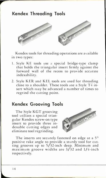
Kendex Threading Tools
Kendex tools for threading operations are available in two types:
I. Style KE tools use a special bridge-type clamp that holds the triangular insert firmly against the forward wall of the recess to provide accurate indexability.
2. Style KER and KEL tools are used for threading close to a shoulder. These tools use a Style T4 insert which may be advanced a number of times to regrind the cutting point.
Kendex Grooving Tools
The Style KGT grooving tool utilizes a special triangular Kendex screw-on type insert to provide three indexable cutting edges and eliminate tool regrinding.
The inserts are securely fastened on edge at a 50 positive rake angle to provide a sturdy tool for cutting grooves tip to 5/32-inch deep. Minimum and maximum groove widths are 3/32 and 1/4-inch respectively.
14

Kendex Heavy Duty Too ls
These tools are designed for more rugged machining on large lathes and boring mills. The thicker inserts used in these tools have cutting edges 1-inch or more in length. They are securely clamped in sturdy ho lders. Replaceable K e n n ametal chip breaker plates are available for jobs where chip control is required.
Kendex Screw-On Insert Tool s
These tools use indexable inserts for jobs where design or size of holder does not permit use of standard clamped Kendex tools.
These tools with 3/8 to I-inch square shanks utilize square, round, or triangular inserts. Freedom from chip obstruction makes them especially suitable for boring bars and small shank sizes as used in screw machines and gang tooling.
1 5

Kendex Boring Bars The Kendex principle of indexable "throw-away"
inserts is also used in Kendex Boring Bars for all types of turret lathes, jig borers, chucking machines, and semiautomatic lathes. Kendex bars are made with steel shanks or with Kennametal tungsten carbide shanks. The latter type (K-Bars) takes advantage of the high rigidity of Kennametal which is three times that of hardened steel. The bars use standard Kendex positive rake square or triangular inserts. Larger sizes are available with fixed or adjustable cutter heads.
Stiffness of Boring Bars
formula for Deflection of Cylindrical Hollow Boring Bars 6.8WL3
y E (D4-d4) Y = deflection in inches d = l.D. of bar in inches
W = force in pounds L= free length of bar in inches E = modulus of elasticity in psi
0= 0.0. of bar in inches
E = 29,500,000 for steel 85,000,000 for Kennametal
The above formula shows that deflection (Y) is inversely proportional to the Young's Modulus of Elasticity of the bar material; also that the deflection of the bar is influenced as follows:
1. By the force (W). 2. By the free length to the third power (t3). 3. By the 0.0. to the fourth power (04). 4. By the 1.0. to the fourth power (d4). The 1.0.
does not greatly influence the deflection. For example, with an 1.0. one-half of the 0.0. the stiffness is reduced by only 6.25 per cent.
1 6
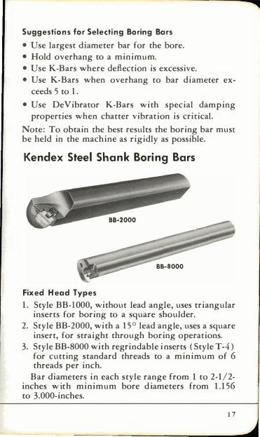
Suggestions for Selecting Boring Bars
• Use largest diameter bar for the bore. • Hold overhang to a minimum. • Use K-Bars where deflection is excessive. • Use K-Bars when overhang to bar diameter ex
ceeds 5 to 1.
• Use DeVibrator K-Bars with special damping properties when chatter vibration is critical.
Note: To obtain the best results the boring bar must be held in the machine as rigidly as possible.
Kendex Steel Shank Boring Bars
Fixed Head Types
1. Style BB-lOOO, without lead angle, uses triangular inserts for boring to a square shoulder.
2. Style BB-2000, with a 15° lead angle, uses a square insert, for straight through boring operations.
3. Style BB-8000 with regrindable inserts ( Style T-4) for cutting standard threads to a minimum of 6 threads per inch.
Bar diameters in each style range from 1 to 2-1/2-inches w ith minimum bore diameters from 1.156 to 3.000-inches.
1 7
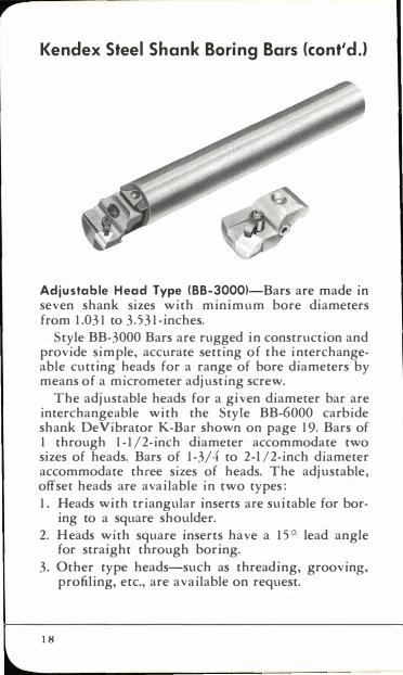
Kendex Steel Shank Boring Bars (cont'dJ
Adjustable Head Type (BB-30001-Bars are made in seven shank sizes with minimum bore diameters from 1.031 to 3.531-inches.
Style BB-3000 Bars are rugged in construction and provide simple, accurate setting of the interchangeable cutting heads for a range of bore diameters by means of a micrometer adjusting screw.
The adjustable heads for a given diameter bar are interchangeable with the Style BB-6000 carbide shank DeVibrator K-Bar shown on page 19. Bars of 1 through 1-1/2-inch diameter accommodate two sizes of heads. Bars of 1-3/4 to 2-l/2-inch diameter accommodate three sizes of heads. The adjustable, offset heads are available in two types: 1. Heads with triangular inserts are suitable for bor
ing to a square shoulder. 2. Heads with square inserts have a 15° lead angle
for straight through boring. 3. Other type heads-such as threading, grooving,
profiling, etc., are available on request.
18
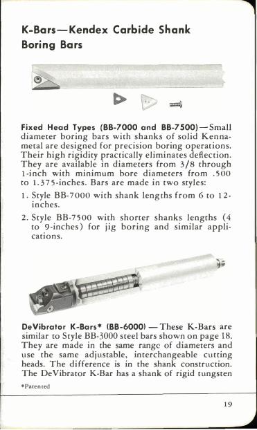
K -Bars -Kendex Carbide Shank
Boring Bars
Fixed Head Types (BB-7000 and BB-7S00)-Small diameter boring bars with shanks of solid Kennametal are designed for precision boring operations. Their high rigidity practically eliminates deflection. They are available in diameters from 3/8 through I-inch with minimum bore diameters from .500 to 1 .375-inches. Bars are made in two styles: 1. Style BB-7 000 with shank lengths from 6 to 12-
inches.
2. Style BB-7500 with shorter shanks lengths (4 to 9-inches) for j ig boring and similar applications.
DeVibrator K-Bars* 18B-60001 - These K-Bars are similar to Style BB-3000 steel bars shown on page 18. They are made in the same range of diameters and use the same adjustable, interchangeable cutting heads. The difference is in the shank construction. The DeVibrator K-Bar has a shank of rigid tungsten *Pacented
1 9
carbide to mInimize deflection on deep bore jobs. Inside the shank are "inertia discs" which counteract chatter and vibration. In addition to the adjustable heads, this bar can be used with fixed heads and threading heads.
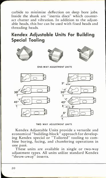
Kendex Adjustable Units For Building Special Tooling
ONE·WAY ADJUSTMENT UNITS
�o � � soJ� C) � 30"-('@ � 3�� O S 0
f---:::: � 45�� S 4S::eI 0 � 0 �
� ki2J � � C) L 10 TWO WAY ADJUSTMENT UNITS
Kendex Adjustable Units provide a versatile and economical "building-block" approach for developing Kendex special or "Tailored" tooling to combine boring, facing, and chamfering operations in one pass.
These units are available in single or two-way adjustment types. All units utilize standard Kendex "throw-away" inserts.
2 0
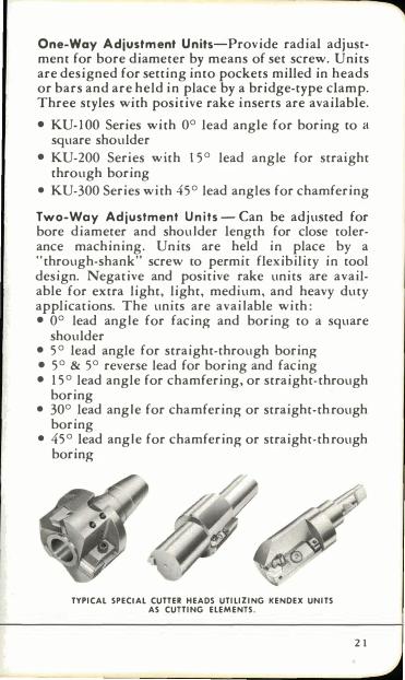
One-Way Adjustment Units-Provide radial adjustment for bore diameter by means of set screw. Units are designed for setting into pockets milled in heads or bars and are held in place by a bridge-type clamp. Three styles with positive rake inserts are available.
• KU-IOO Series with 0° lead angle for boring to a square shoulder
• KU-200 Series with 15° lead angle for straight through boring
• KU-300 Series with 45° lead angles for chamfering
Two-Way Adjustment Units - Can be adjusted for bore diameter and shoulder length for close colerance machining. Units are held in place by a "through-shank" screw co permit flexibility in cool design. Negative and positive rake units are available for extra light, light, medium, and heavy duty applications. The units are available with: • 0° lead angle for facing and boring to a square
shoulder • 5° lead angle for straight-through boring • 5° & 5° reverse lead for boring and facing • 15° lead angle for chamfering, or straight-through
boring • 30° lead angle for chamfering or straight-through
boring • 45° lead angle for chamfering or straight-through
boring
TYPICAL SPECIAL CUTTER HEADS UTILIZING KENDEX UNITS AS CUTTING ELEMENTS.
2 1
,... Kenloc HThrow-Away" Insert Tools
The Kenloc tooling system provides the most eco
nomical and versatile indexable insert tooling for all general purpose machining operations.
A simple yet effective lock pin design, illustrated on page 23, provides positive locking of the Kenloc insert.
Kenloc insert with molded chip control grooves provides up to eight indexable cutting edges.
Kenloc tools are available in a wide range of styles and shank sizes with cutting angles that conform to basic industry standards.
The Kenloc tooling system consists of the following three main types:
1. Kenloc tools with triangular, square, and round inserts.
2. Kenloc tools which utilize 800 diamond inserts with radii on all four corners for cutting to a square shoulder or with a lead angle.
3. Kenloc Pre-Set tools having same geometry as the Kenloc diamond insert tools, but with four holder adjusting screws to permit pre-setting when used in numerical ly-controlled machines.
Kenloc Tool Features • Positive insert locking-no shift or flutter
• Low holder profile minimizes chip interference and tool overhang
• Quick indexing with partial turn of lock cup
• Economical Kenloc inserts with pre-formed chip control grooves
2 2
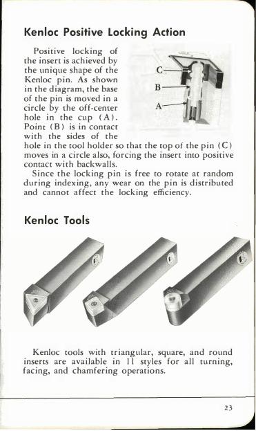
Kenloc Positive Locking Action
Positive locking of the insert is achieved by the unique shape of the C---l-Kenloc pin. As shown in the diagram, the base of the pin is moved in a circle by the off-center hole in the cup ( A). Point (B ) is in contact with the sides of the hole in the tool holder so that the top of the pin ( C) moves in a circle also, forcing the insert into positive contact with backwalls.
Since the locking pin is free to rotate at random during indexing, any wear on the pin is distributed and cannot affect the locking efficiency.
Kenloc Tools
Kenloc tools with triangular, square, and round inserts are available in 11 styles for all turning, facing, and chamfering operations.
23
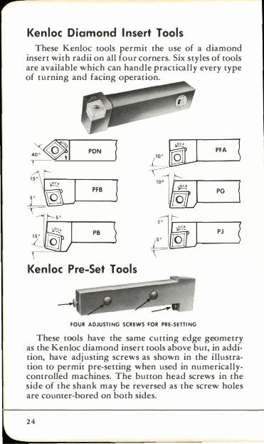
Kenloc Diamond Insert Tools These Kenloc tools permit the use of a diamond
insert with radii on all four corners. Six styles of tools are available which can handle practically every type of turning and facing operation.
PDN I 10· i[J..--1 P---JFA �
". [jjl--_
PG-J
s
1
t"-
L!JjJ�PJ----,{
Kenloc Pre-Set Tools
FOUR ADJUSTING SCREWS FOR PRE-SETTING
These tools have the same clltting edge geometry as the Kenloc diamond insert tools above but, in addition, have adjusting screws as shown in the illustration to permit pre-setting when used in numericallycontrolled machines. The button head screws in the side of the shank may be reversed as the screw holes are counter-bored on both sides.
24
Kenna meta l Standard Kendex Insert Nu mbering Syste m
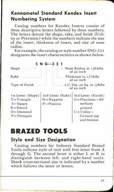
Catalog numbers for Kendex Inserts consist of three descriptive letters followed by three numbers. The letters denote the shape, rake, and finish (Utility or Precision) while the numbers indicate the size of the insert, thickness of insert, and size of nose radius.
For example, the catalog or style number SNG-32 1 designates the insert characteristics as shown below.
S N G-3 2 Shape
Rake ..
Type of Finish
1 st Letter (Shape)
T=Triangle
S=Square
R=Round
D=Diamond
P=Pentagon
. .Nose Radius in 1 /64ths of an inch
.. .Thickness i n 1 / 1 6ths of an inch
.. I.e. Dia. or Sq. in 1/8ths of an i nch
2nd Letter (Rake) 3 rd Letter (Finish)
N=Negative G=Precision-All
P= Positive surfaces
ground
U=Utility
Ground top
and bottom
BRAZED TOOLS St yle and Size Designation
Catalog numbers for Industry Standard Brazed Tools indicate style of tool with first letter from A through G. The second letter is either L or R to d istinguish between left- and right-hand tools . Shank cross-sectional size is indicated by a number which follows the letter or letters.
25
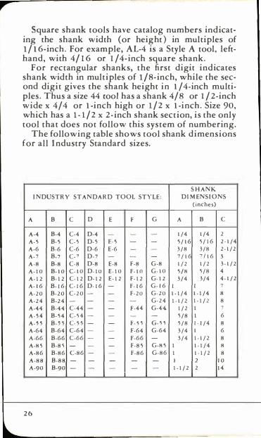
,.. Square shank tools have catalog numbers indicat
ing the shank width (or height) in multiples of l/ 1 6-inch_ For example, AL-4 is a Style A tool, lefthand, with 4/16 or l/4-inch square shank.
For rectangular shanks, the first digit indicates shank width in multiples of liS-inch, while the second digit gives the shank height in I/4-inch multiples_ Thus a size 44 cool has a shank 4/s or liZ-inch wide x 4/4 or I-inch high or liz x I-inch_ Size 90, which has a I-liz x Z-inch shank section, is the only tool that does not follow this system of numbering.
The following table shows tool shank dimensions for all Industry Standard sizes.
SHANK
INDUSTRY STANDARD TOOL STYLE: DIMENSIONS
(inches)
A B C 0 E F G A B C
A-4 B-4 C-4 0-4 1/4 1/4 2
A-S B-S CoS D-s F.-S S/16 S/16 2-1/4
A-6 B-6 C-6 0-6 E-6 3/8 3/8 2-1/2
A-7 B-7 C-7 0-7 7/16 7116 3
A-8 B-8 C-8 0-8 E-8 F-8 G-8 1/2 1/2 3-1/2
A-IO B-IO C-1O 0-10 E-IO F-IO G-IO SIB �/8 4
A-12 B-12 C-12 0-12 E-12 F-12 G-12 3/4 3/4 4-1/2
A-16 B-16 C-16 0-16 F-16 G-16 1 1 7 A-20 B-20 C-20 - F-20 G-20 1-1/4 1-1/4 8
A-24 B-24 G-24 1-1/2 1-1/2 8
A-44 B-44 C-44 - F-44 G-44 1/2 1 7 A-H B-S4 C-H - �/8 1 6
A-SS B-S � C-55 F-S 5 G-SS 5/8 1-1/4 8
A-64 B-64 C-64 - F-64 G-64 3/4 1 6
A-66 B-66 C-66 - 1'-66 3/4 1-1/2 8
A-BS B-85 F-8S G-BS 1 1-1/4 R A-86 B-86 C-86 - F-86 G-86 I 1-1/2 8
A-88 B-88 1 10
A-90 B-90 1-1/2 2 14
26
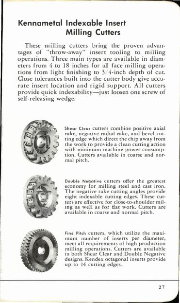
Kennametal Indexable Insert Milling Cutters
These milling cutters bring the proven advantages of "throw-away" insert tooling to milling operations. Three main types are available in diameters from 4 to 18 inches for all face milling operations from light finishing to 3/4-inch depth of cut. Close tolerances built into the cutter body give accurate insert location and rigid support. Al l cutters provide quick indexability-just loosen one screw of self-releasing wedge.
Shear Clear cutters combine positive axial rake, negative radial rake, and bevel cutting edge which direct the chip away from the work to provide a clean cutting action with minimum machine power consumption. Cutters available in coarse and normal pitch.
Double Negative cutters offer the greatest economy for milling steel and cast iron. The negative rake cutting angles provide eight indexable cutting edges. These cutters are effective for close-to-shoulder miling as well as for flat work. Cutters are available in coarse and normal pitch.
Fine Pitch cutters, which utilize the maxi· mum number of inserts per diameter, meet all requirements of high production milling operations. CutterS are available in both Shear Clear and Double Negative designs. Kendex octagonal inserts provide up to 14 cutting edges.
27
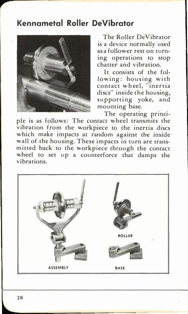
Kennametal Roller DeVibrator
The Roller De Vibrator is a device normally used as a follower rest on turning operations to stop chatter and vibration.
It consists of the following: housing with contact w h eel, "inertia discs" inside the housing, supporti ng yoke, and mounting base.
The operating principle is as follows : The contact wheel transmits the vibration from the workpiece to the inertia discs which make impacts at random against the inside wall of the housing. These impacts in turn are transmitted back to the workpiece through the contact wheel to set up a counter force that damps the vibrations.
ROllER
ASSEMBLY BASE
28
CUTTING GRADES A. Grade System
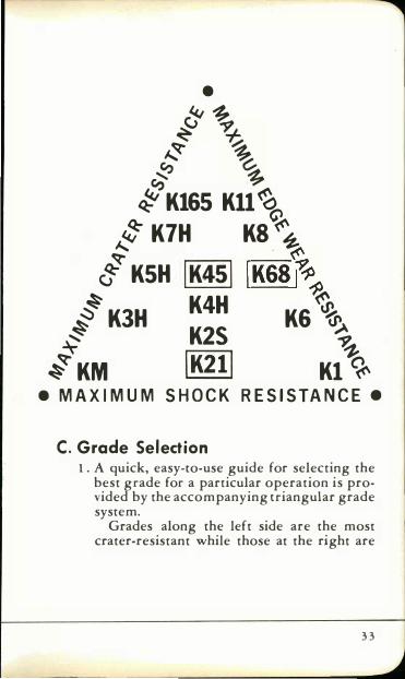
Kennametal has long recognized the basic characteristics of the metal cutting process and, as a result, has made available the accompanying grade system or network of standard grades in the form of a triangle. This network of grades provides an optimum coverage of the entire range of the machining area and tool life requirements. The Kennametal grades in the triangle illustrated on Page 33 are arranged according to their resistance to abrasion, cratering, edge-wear, and shock. There is a Kennametal grade with specific characteristics to meet any combination of machining requirements to provide optimum performance. However, three basic grades, K21, K68 and K45 will machine 90% of your jobs.
B. Grade Description Following is a brief description of the fourteen standard Kennametal Cutting Grades: 1. Crater- Resistant Grade
K7H 93.5 RA; 11.10 density; 150,000 psi TR. High hardness crater-resistant grade for high-velocity machining at light to moderate chip loads. KSH 93.0 RA; 11.50 density; 200,000 psi TR. Stronger than K7H and more wearresistant that K3H. For semi-finishing cuts on clean steel. K3H 91.7 RA; 11.10 density; 250,000 psi TR. General purpose crater-resistant grade stronger than K5H and more wear-resistant than KM. For moderate cuts on carbon and alloy steels of 0.30 C and above, also for medium to heavy cuts on soft steels with less carbon.
29
,..
30
KM 91.0 RA; 12.90 density; 300,000 psi TR. Strongest crater-resistant grade for heavy chip loads and interrupted roughing cuts. Not as durable as K3H.
2. Crater and Edge-Wear Resistant Grades
K45 92.5 R,,; 12.20 density; 250,000 psi TR. Harder and more wear resistant than K4H but equal in toughness. For moderate roughing and finishing cuts on steel with light to heavy chip loads.
K4H 92.0 R,,; 12.50 density; 250,000 psi TR. Harder than K2S but with moderate strength. For moderate to light chip loads on steel in form tools, large nose radius, or tools that must dwell.
K2S 91.5 RA; 12.90 density; 275,000 psi TR. Stronger than K4H and more wearresistant than K21. For heavy to moderate chip loads on medium roughing operations of moderate interruption. Also for long dry cuts where thermal deformation is a problem. K21 91.0 RA; 12. 30 density; 250,000 psi TR. General purpose crater- and edgewear resistant grade. Stronger than K2S but not as wear-resistant. For moderate to heavy chip loads on roughing cuts or severe interruptions. Highly resistant to thermal shock.
3. Edge-Wear Resistant Grades
K 11 93.0 RA; 15.20 density; 175,000 psi TR. Highly edge-wear resistant in fine finishing of ferrous and no n-ferrous metals and plastics. More wear-resistant than K8 but not as strong.
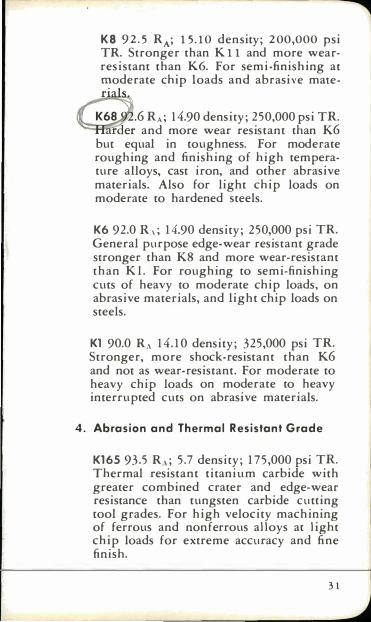
K8 92.5 RA; 15.10 density; 200,000 psi TR. Stronger than K 11 and more wearresistant than K6. For semi-finishing at �oderate chip loads and abrasive mate-
.6 RA; 14.90 density; 250,000 psi TR. "Ci::::c�1er and more wear resistant than K6
but equal in toughness. For moderate roughing and finishing of high temperature alloys, cast iron, and other abrasive materials. Also for light chip loads on moderate to hardened steels.
K6 92.0 R,; 14.90 density; 250,000 psi TR. General purpose edge-wear resistant grade stronger than K8 and more wear-resistant than K l . For roughing to semi-finishing cuts of heavy to moderate chip loads, on abrasive materials, and light chip loads on steels.
Kl 90.0 R" 14.10 density; 325,000 psi TR. Stronger, more shock-resistant than K6 and not as wear-resistant. For moderate to heavy chip loads on moderate to heavy interrupted cuts on abrasive materials.
4. Abrasion and Thermal Resistant Grade
K165 93.5 R,,; 5.7 density; 175,000 psi TR. Thermal resistant titanium carbide with greater combined crater and edge-wear resistance than tungsten carbide cutting tool grades. For high velocity machining of ferrous and nonferrous alloys at light chip loads for extreme accuracy and fine finish.
3 1
,...
Special Purpose Grades
Although every effort is made to broaden the overall area of application of standard grades and to minimize the number of these grades, there nevertheless exists the need for special purpose grades possessing special properties. These properties are achieved primarily by composition changes and manufacturing processes. These grades are for work materials which have machining characteristics that require certain unique properties.
3 2
A typical special purpose Grade is C8735. This grade is similar to K6 but has increased resistance to build-up characteristics. It is used for light chip load, low-speed machining as in broaching of high tensile strength alloyed cast iron where abrasion resistance is required due to the light chip load; also, resistance to galling or build-up due to the relatively slow speeds.
Other special grades are available for specific operations such as machining hot flash formed on welded tu bing and for machining urani urn.
• ��
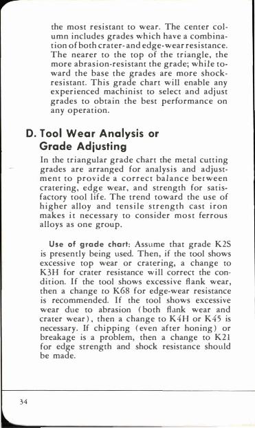
� � ,,� � '? �-� 7 �K165 Kll\
# K7H K8 \'<'� g KSH IK4S1 IK68�l1 � K3H K4H K6 � � K2S �
� � � KM \K211 Kl �
• MAXIMUM SHOCK RESISTANCE.
C . Grade Selection 1. A quick, easy-co-use guide for selecting the
best grade for a particular operation is provided by the accompanying triangular grade system.
Grades along the left side are the most crater-resistant while those at the right are
3 3
,..
34
the most resistant to wear. The center column includes grades which have a combination of both crater- and edge-wear resistance. The nearer to the top of the triangle, the more abrasion-resistant the grade; while toward the base the grades are more shockresistant. This grade chart will enable any experienced machinist to select and adjust grades to obtain the best performance on any operation.
D. Tool Wear Analysis or Grade Adjusting In the triangular grade chart the metal cutting grades are arranged for analysis and adjustment to provide a correct balance between cratering, edge wear, and strength for satisfactory tool life. The trend toward the use of higher alloy and tensile strength cast iron makes it necessary to consider most ferrous alloys as one group.
Use of grade chart: Assume that grade K2S is presently being used. Then, if the tool shows excessive top wear or cratering, a change to K3H for crater resistance will correct the condition. If the tool shows excessive flank wear, then a change to K6S for edge-wear resistance is recommended. If the tool shows excessive wear due to abrasion ( both flank wear and crater wear), then a change to K4H or K45 is necessary. If chipping ( even after honing) or breakage is a problem, then a change to K21 for edge strength and shock resistance should be made.
MACHINING HINTS Modern materials vary greatly in cutting charac
teristics, and must be machined with suitable techniques. The following hints on machining the more common of them are intended as an aid in setting up jobs initially. On long runs or repetitive jobs, adjustments may be made by analysis of tool wear.
Steel Carbon and Alloy Steels-These have much the same cutting characteristics. Both cut with a continuous chip and form a built-up edge on the tool if run at low speeds. As speed increases, a "critical" point is reached above which the built-up edge is swept away and cutting is more efficient, tool life greatly extended, and finish improved. This critical speed is affected by hardness of the steel, chip thickness, and to a lesser degree by the depth of cut. Good cutting practice is usually 50% to 1 00% above critical speed. Reference to the table of recommended speeds for machining steel with Kennametal will show that soft "gummy" steels, such as boiler plate or SAE 1010, require very high machining speeds to remain safely above the critical and thus cut efficiently , whereas steel hardened to 300 Brinell cuts efficiently at less than 1/2 the speed. Similarly, light cuts (chip thickness and depth) require more speed than heavy cuts.
Because of the strong, continuous chip, steel tends to crater or erode the top face of the tool, and grades of Kennametal designed to resist this action are therefore required. A fiat chip will curl away from the top face of the tool with comparatively light force, whereas the same amount of steel in a channel shaped chip has greater structural rigidity and re-
3 5
,... quires more force to deflect. When the tool has a large nose radius, a curved or channel cross section is produced in the chip thus requiring higher tool pressure and power. When the tool has a small nose radius, a flat ribbon-like chip is produced, tool life is better, and less power is required. For this reason a small nose radius is recommended for Kennametal steel-cutting tools when the operation makes this possible. Stainless Steels-From the standpoint of machining characteristics, these steels divide into two groups: The hardenable (magnetic), and the austenitic (nonmagnetic) . Hardenable stainless steels machine much the same as alloy steels of equal hardness, and the foregoing recommendations will apply. Austenitic stainless steels such as 18-8, type 300, etc., are work hardening, yet soft and gummy in their tendency to tear and to build up on the cutting edge. The build-up tendency calls for high speed, whereas the work-hardened chip and machined surface call for speeds in the lower ranges to prevent excessive tool wear. The best condition is therefore a compromise, with a feed rate heavy enough to get under the work-hardened surface of the previous stroke or revolution, and a speed high enough to avoid excessive build-up, recognizing that tool life wil l be shorter than with equivalent jobs on other steels. High Manganese Steels-For applications involving severe impact and wear, steels with 12% to 14% of manganese are frequently used because of their extreme work-hardening properties. These parts can be successfully machined with grade K2S Kennametal at speeds of 35 to 1 00 feet per minute and feeds not less than .015/1. If a finishing cut is to be taken, at least 1/32", and preferably 1/16", stock should be allowed so that the finishing tool can get under the work-hardened surface.
36
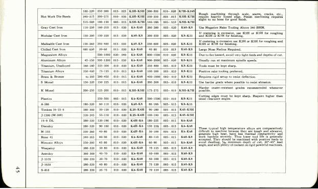
Cast Iron Gray Iron-This machines with a crumbling chip and has very little tendency to build up along the cutting edge. Machining techniques are therefore quite different than for steel. Because of freedom from a built-up edge, there is no lower limit or critical speed to be considered, and tool wear is almost directly proportional to speed of cutting. Speeds up to 400 ft. per min., depending upon feed rate and depth of cut, are common. For normal cutting, such as .025" feed and .200" depth of cut, speeds of 275 ft. per min. where pieces per tool grind is important, and up to 350 ft. per min. where cutting speed is more important than tool life, are common.
The low-strength chip breaks i nto a crumbly powder, so a large nose radius permits better finish, faster feed, and longer tool l ife.
High Tensile Cast Iron-Addition of alloys such as nickel, or use of steel scrap in cast irons to obtain higher strength cast irons, has become almost universal. These additions have little effect on the machining characteristics except that the chip is mechanically stronger and has some tendency to crater the top surface of the tool. The edge wear resistant grades of Kennametal ( Kl, K6, K68, and K8 ) have had ego ugh of the crater-resistant carbides added to them to resist this mild cratering. O n some high tensile iron it is necessary to use more crater resistant grades (K21, K4H), especially if higher speed ranges are used.
Chilled Iron-Surfaces of cast-iron parts deliberately chilled to high hardnesses, such as rolling mill rolls, are very abrasive on the cutting tools. Tool life is extended to a practical range by use of lower cutting
37
,... speeds and stretching the chip out over a long cutting edge to finish the job with a minimum of footage passing over the cutting edge. Use of large diameter rounds or extreme lead angles on longitudinal feeds, or broad tools on cross feeds, accomplish this purpose. K6 or K8 are used for edge-wear resistance.
Non- Ferrous Materials
Copper Alloys-The alloys of copper machine with a low strength chip and can be run 500 to 1000 ft. per min. with a good tool life. The aluminum bronze alloys have some tendency to build up on the cutting edge, but a speed of 250 to 500 ft. per min. , depending upon hardness, will prevent this buildup. Grade K6 or K68 is generally used. Al uminum and Magnesium Al loys -These lightweight alloys machine readily with K6, K68 or K8 Kennametal at speeds over 500 ft. per min. The low tensile chip exerts little pressure on the tool. Rakes and clearances may therefore be increased to as much as 150 for greater life and freer cutting. Plastics-None of the common types present great machining problems but when they are coinbined with fillers or fibers such as clay, asbestos, cotton, paper, glass, etc., they may become quite abrasive. The more abrasive the filler, the lower the practical machining speed and shorter the tool life. Use of K6, K68, K8 or K i l Kennametal to resist wear and speeds of 200 to 12,000 ft. per min., depending upon abrasive qualities and desired tool life, are recommended.
Use of the foregoing suggestions will give satisfactory tool performance on practically all jobs, but if the volume of work justifies further investigation, tool performance can often be improved by a test run. A logical procedure is given on pages 51 and 52.
38
High Strength Steels There is con sid era ble overlapping o f high
strength steels or ultra-high strength steels (iron base alloys) and high temperature alloys (iron base, nickel base, and cobalt base a l loys) . The high strength steels are those with tensile strength levels of 200,000 psi to 400,000 psi from room temperature to a few hundred degrees fahrenheit. The high temperature alloys also have high tensile strength but are able to retain their strength to much higher temperatures.
Most steels in the general category of high strength steels can be readily machined with the harder grades K45, K5H, and K7H which are intended for machining steel. The cutting edges must be moderately to heavily honed to insure maximum edge strength.
A suitable cutting fluid is recommended primarily to serve as a coolant for removing the high heat generated in the chip making process. Adequately powered machine tools should be used as the forces of cutting are very high due to higher tensile strength levels. The tool shank should be as large as permissible and as sturdy as possible. The workpiece must be well clamped or chucked and well supported to avoid loosening due to machining forces.
Depending on the hardness of the workpiece, feeds should be reduced by 10 to 20% and speeds by 20 to 50% of those used for most alloy steels in order to obtain reasonable tool life.
Positive rake Kendex tools with 150 or 300 lead angle should be used wherever possible. Negative rake Kendex tools of the same lead angle should be used only when it is necessary to avoid excessive
3 9
chipping and/or breakage of the insert. A positive rake insert of a tough grade, moderately honed to avoid edge breakdown, will generally be found most suitable.
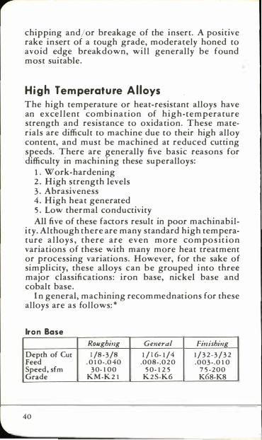
H i g h Te mperature A llo ys The high temperature or heat-resistant alloys have an excellent combi nation of high-temperature strength and resistance to oxidation. These materials are difficult to machine due to their high alloy content, and must be machined at reduced cutting speeds. There are generally five basic reasons for difficulty in machining these superalloys:
1. Work-hardening 2. High strength levels 3. Abrasiveness 4. High heat generated 5. Low thermal conductivity All five of these factors result in poor machinabil
ity. Although there are many standard high temperature a l loys , there are even more compos it ion variations of these with many more heat treatment or processing variations. However, for the sake of simplicity, these alloys can be grouped into three major classifications: iron base, nickel base and cobalt base.
In general, machining recommednations for these alloys are as follows: *
Iron Base
Depth of Cut Feed Speed, sfm Grade
40
Roughi,lg 1 /8-3/8
. 0 1 0-.040 30- 1 00
KM-K 2 1
General 1 / 1 6- 1 /4
.008-.02 0 5 0- 1 2 5
K 2 S-K6
Fi,lishing 1 / 3 2 - 3 / 3 2 .003-.0 1 0
7 5 - 2 00 K68-K8
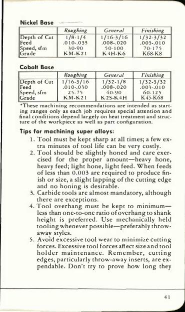
Nickel Base
Roughing General Finishing Depth of Cut 1 /8- 1 /4 1 / 1 6- 3 / 1 6 1 / 3 2- 3 / 3 2 Feed .0 1 0-.0 3 5 .008-.020 .003-.0 1 0 Speed, sfm 3 0-90 5 0- 1 00 7 0- 1 7 5 Grade KM-K2 1 K4H-K6 K6B-KB
Cobalt Base Roughing General Finishing
Depth of Cut 1 / 1 6- 3/ 1 6 1 /3 2 - 1 /8 1 / 3 2 - 3 / 3 2 Feed .0 1 0-.0 3 0 .008-.020 .003-.0 1 0 Speed, sfm 2 5- 7 5 4 0-90 60- 1 2 5 Grade KM-K2 1 K 2S-K4 H K45-K6B
*These machi n ing recommendations are intended as starting ranges only as each job requires special attention and final conditions depend largely on heat treatment and structure of the workpiece as well as part configuration.
Tips for machining super alloys:
1. Tool must be kept sharp at all times; a few extra minutes of tool life can be very costly.
2. Tool should be slightly honed and care exercised for the proper amount-heavy hone, heavy feed; light hone, light feed. When feeds of less than 0.003 are required to produce finish or size, a slight lapping of the cutting edge and no honing is desirable.
3. Carbide tools are almost mandatory, although there are exceptions.
4. Tool overhang must be kept to minimumless than one-to-one ratio of overhang to shank height is preferred. Use mechanically held tooling whenever possible-preferably throwaway styles.
5. Avoid excessive tool wear to minimize cutting forces. Excessive tool forces affect size and tool holder mai ntenance. Remember, cutti ng edges, particularly throw-away inserts, are expendable. Don't try to prove how long they
4 1
,... can last. Don't trade dollars in machine time for pennies in tool cost.
6. Use positive rake tools wherever possible. 7. Use negative rake tools only where necessary
and where surface speeds can be kept in the higher ranges.
8 . Machine tool must be kept rigid. 9. Machine tool should be "overpowered."
10. Workpiece must be well clamped. 1 1. Workpiece must be supported to avoid flexing. 12. Depth of cut should be deep enough to avoid
glazing. 13. Feed should be positive to avoid dwelling
and work-hardening. 14. Minimum chip discoloration is desirable. 15. Each job requires special consideration. This
requires ingenuity on the part of tool engineers.
Above all, it is important to keep in mind that the same good shop practice that is applied in machining carbon and alloy steels should be observed. However, in machining high temperature alloys such practices are mandatory.
Because these alloys are relatively difficult to machine and each alloy requires special attention, we invite you to get in touch with your Kennametal Carbide E ngineer for assistance in establishing optimum tool performance.
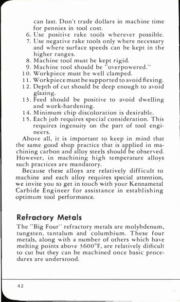
Ref ractory Metals The "Big Four" refractory metals are molybdenum, tungsten, ta ntalum and columbium. These four metals, along with a number of others which have melting points above 3 600°F, are relatively difficult to cut but they can be machined once basic procedures are understood.
4 2
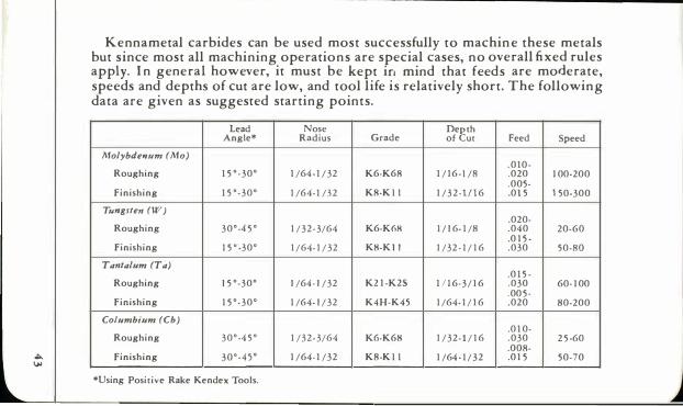
Kennametal carbides can be used most successfully to machine these metals but since most all machining operations are special cases, no overall fixed rules apply. In general however, it must be kept in mind that feeds are moderate, speeds and depths of cut are low, and tool life is relatively short. The following data are given as suggested starting points.
Lead Nose Depth Angle* Radius Grade of Cut Feed Speed
Molybde'lIIm (Mo) . 0 1 0 ·
Roughing 1 5 ' · 30' 1 /64 . 1 / 32 K6·K6S 1 / 1 6 · I /S ,020 1 00·200 ,005-
Finishing 1 5 '-30' 1 /64- 1 /3 2 KS-K I I 1 / 3 2 · 1 ( \ 6 ,0 1 5 1 50-300
Ttmgsten (IV) .020-
Roughing 30'-4 5 ' 1 / 3 2 - 3/64 K6-K6B 1 / 1 6- 1 /8 ,040 20-60 ,0 1 5 -
Finishing 1 5 ' -30' 1 /64- 1 / 32 KS-K I I 1 /32 - 1 / 1 6 ,030 50-SO
Tan/alum (Ta) .0 1 5 -
Roughing 1 5 '-30' 1 /64 · 1 /32 K2 1 -K2S 1 ( \ 6· 3 / 1 6 ,030 60- 1 00 ,00 5 ·
Finishing 1 5 '-30' 1 /64- 1 / 32 K4H-K45 1 /64- 1 / 1 6 ,020 80-200
Columbium (Cb) .0 1 0-
Roughing 30'-4 5 ' 1 /3 2 - 3/64 KG·K6S 1 / 3 2 - 1 / 1 6 .030 2 5 ·60 ,OOS-
of>.. Finishing � 3 0 ' - 4 5 ' 1 /64. 1 /32 KS-K I I 1 /64 · 1 / 3 2 .0 1 5 50-70
� *Using Positive Rake Kendex Tools.
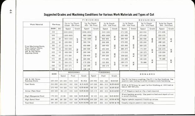
... ... Suggested Grades and Machining Conditions for Various Work Materials and Types of Cut F I N I S H I N G R O U G H I N G
Work Material Hardneq Up to IA. Depth lA, :tn. Depth �--% Depth Y._ l,i Depth %-'A Depth % & Up Depth Und� OOS Feed 005- 015 Feed 010- 030 Feed 02D- 050 Feed 03D- . 070 Feed 040-,100 Feed
BHN RC Sp«d Grade Sp«d Grade Sp«d Grade Sp«d Or.d� Sp«d Grade Sp«d Grade
150 1500-2000 1000 1600 500-1 200 315-500 300-<50 275400
200 1 200-1800 ----;oo:J2OO :l � i!: '""""Ji"HsO ---;;s:::;;s , 250-375
250 " 800-l S00 � � '< � '" JO(HOO ;:; 2ScHOO :; I 225-350 � 300 32 650-850 '" � � � rn=JSO '" I 200-325
'" Free Machinina Steel" 350 37 550 700 ----.00::600 i!' --;oo:::;so '" � � '� I 1 75- 300 Plain Carbon Steeil, .00 3SHsO '" - :2 � - f---Alloy Steeb. and 43 450 600 i!' 250 ...... 00 1 75-300 � 1 50- 215
400 & SOO Series 42S .. 400-550 '" JoCHoO ----rn:J5O I 1 75-250 --;so=rn '" I 1 25-250 ;:; Stainless Steel. � :;; � '" I )50-225
� rn:2SO I 106-225 450 47 375-500 :2 '" I 200-300
'" � --.-;s::;oo 1""00-225 � 47S •• 330-400 '" i2 r-rn--m- � � ----;s:;oo f--- :e so. 51 300-375 � � '" '" m 53 250 375 I 1 25-200
'" ---.oo:i7S '" � '" - f---SSO SS 200-275 I l OG - I SO
- - - I-ROUGHING FINISHING
BHN R E M A R K S Sp«d F"'" Grade Sp«d F"'" Grllde
200 & 300 5es'in UM: KI (or heavy rouchina. Ulle K l l (or fine finishina;_ UK SlainJ", Stech IS()-.2S0 12S�300 OIS 02> KI·Kft 250--600 010� 020 K08·K8 �itive rake toolin& to avoid excessive work hardening.
Ca.t St�'. IS()-.280 180�2S0 OIS 030 K 2 1 · K1S 2<41')-500 005- 0 1 5 K1S·K4l1 KSH or K7H may be uacd rOf" fine finiahin& at .005 reed or
2!>O ..... 00 '<40 200 012 02> K1S·K4H 1 80�3S0 005- 010 K4H·K45 leu at 400-600 .rm. ArmOf" Plate Steel 250 320 80- 125 010 020 K1S·K411 125-175 .oS OIS K45·K5U 3°' 5° Ne,ative land at I...., II. reed required.
Hiah Manganeae Steel 1 70-210 35 80 020- 030 K1S-K4H 50-125 015- 020 K45-K51-1 Work harden. KVCTely. UK �itive reed and depth or cut to avoid dwelling.
Hiah Speed Steel 200 320 120 220 010- 020 K.UI·K5H 200 350 005- OIS K.5H·K71-1 Hi,hcr ,peed, required ir build·up occur •.
Tool Steel ISO 225 ISO 230 010 020 K311·K511 200-300 005- 015 K5H· K7 1-1 U.ually require poIitive rake tooling.
TOOL PERFORMANCE Previous sections of this manual have dealt with
tool selection, choosing the proper grade of Kennametal to use, and specific recommendations for speeds and feeds for various materials to be cut. After having followed these recommendations, tool performance should be examined to determine whether the number of pieces per cutting edge is adequate; whether the cost per piece is in l ine with other jobs.
Tool performance is an evaluation of the production cost per workpiece produced. After all measures of cost and performance have been made, it is the cost of the finished piece that is most important. This means that tool performance is not an independent or arbitrarily established measure, but one which is a distinct part of the over-all production operation.
There is a minimum tool performance which must be achieved and this is generally established from previous data concerning the job. I nformation that follows in this manual will aid in checking tool troubles which can cause unacceptable performance. But even when the tools are performing satisfactorily, production costs may be unnecessarily high.
Tool life, which is most generally stated in units of time, is the key to production economics. With the advent of the indexable "throw-away" insert Kendex tooling, tool life took on new significance. Tool change time, which previously had been an important element in downtime, became a very small part of the nonproductive part of an operation. The critical need to "make the tool last," in order to reduce costly tool changing, was eliminated. However, due to the entrenched practice of measuring tool life in units of time, the potential advantages
46
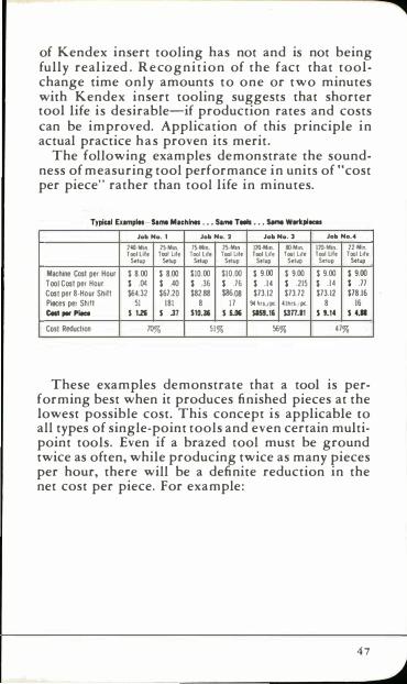
of Kendex insert tooling has not and is not being fully real ized . Recognition of the fact that toolchange time only amounts to one or two minutes with Kendex insert tooling suggests that shorter tool life is desirable-if production rates and costs can be improved. Application of this principle in actual practice has proven its merit.
The following examples demonstrate the soundness of measuring tool performance in units of " cost per piece" rather than tool life in minutes.
TypiOiI ElImpi .. Sa,.. Machi ... . . . SI,.. Tills • . . Sarno wwtpi_ Job No. 1 Job No. 2 Job No. 3 Job No.4
24O· lrllhn 2S·Mln. 1S·M!n. lS·Mln 1M-Min. !I)·Mln. 120-Mln. 22·Mln. Tool life TOO/ lile Too/ lile TooI lJle Tool LJle Toof l.le Tool lJfe Too/ lile
Selup Setup Setup Setup Setup Setup Setup Setup
Machine Cost per Hour $ 8.00 $ 8.00 $10.00 $10.00 $ 9.00 $ 9.00 $ 9.00 $ 9.00 Tool Cosl per Hour $ .04 $ .40 $ .36 $ .76 $ .14 $ .215 $ .14 $ .77 Cosl per 8·H""r Shift $64.32 $67.20 $82.88 $86.08 $73.12 $73.72 $73.12 $78.16 Pieces per Shift 51 181 8 1 7 94 h(s./pc.. 41hfS.{pc. 8 16 em ,or Ploco I 1.26 I .37 110.36 1 5.0& SI59.16 Im .. l 1 '.14 1 4.a Cost Reduclion 70% 51% 56% 47%
These examples demonstrate that a tool is performing best when it produces finished pieces at the lowest possible cost. This concept is applicable to all types of single-point tools and even certain multipoint tools. Even if a brazed tool must be ground twice as often, while producing twice as many pieces per hour, there will be a definite reduction in the net cost per piece. For example:
47
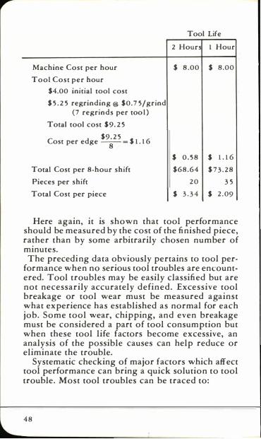
Tool Life
2 Hours 1 Hour
Machine Cost per hour $ 8 .00 $ 8.00
Tool Cost per hour
$4.00 initial tool cost
$ 5 . 2 5 regrinding @ $0.7 5/grind
(7 regrinds per too l )
Total tool cost $9. 2 5
$9. 2 5 Cost per edge -
8- = $ 1 . 1 6
$ 0 . 5 8 $ 1 . 1 6
Total Cost per 8-hour shift $68.64 $ 7 3 . 2 8
Pieces per shift 2 0 3 5
Total Cost per piece $ 3 . 3 4 $ 2 . 09
Here again, it is shown that tool performance should be measured by the cost of the finished piece, rather than by some arbitrarily chosen number of minutes. The preceding data obviously pertains to tool per
formance when no serious tool troubles are encountered. Tool troubles may be easily classified but are not necessarily accurately defined. Excessive tool breakage or tool wear must be measured against what experience has established as normal for each job. Some tool wear, chipping, and even breakage must be considered a part of tool consumption but when these tool life factors become excessive, an analysis of the possible causes can help reduce or eliminate the trouble.
Systematic checking of major factors which affect tool performance can bring a quick solution to tool trouble. Most tool troubles can be traced to:
48
1 . Machine conditions.
2 . Variations i n the material being cut.
3. I mproper tool selection.
4. I n correct s p e e d s a n d feeds.
5. Poor chip control.
6. Use of the wrong grade of carbide.
7. I m proper grinding.
When tool trouble develops, check the job against the previous operating conditions to determine whether any changes or deviations have occurred in any of these seven factors. Such a check may provide a clue to the trouble. The following section, "Trouble Shooting," lists possible causes of tool trouble grouped according to the nature of the trouble being experienced. This listing is another aid to locating the cause of tool troubles. Complete details of analysis of tool wear and tool breakage are presented in the next section of this manual.
Trou ble Shooting Some of the more common troubles which occur
on the j ob are chippi ng, cracking or breaking, chatter, torn finish, wear, crater, and glaze. Some of the common causes of such troubles are:
Chipping 1 . "Saw toothed" or too keen a cutting edge. 2. Chip breaker too narrow. 3. Chatter. 4. Scale or i nclusions. 5. Incorrect grade. 6. Too much relief. 7. Lack of rigidity. 8. I mproper grinding.
Cracking or Breaking 1 . Feed tOO heavy. 2. Worn or chipped cutting edges. 3. I mproperly applied coolant. 4. Too much rake or relief. 5. Too much overhang. 6. Lack of rigidity in set-up. 7. Speed toO slow. 8. Too much variation i n depth of cut for size of tip. 9. Incorrect grade. 1 0. Chatter. 1 1 . Braze or grinding strains. 1 2 . Built-up edges.
49
ChaHer 1 . Tool not on ce nter. 2. I nsufficie nt relief or. clearance. 3 . Too much rake. 4. Too much overha n g . 5. Nose radius too large. 6. Feed too high. 7_ Lack of rig id ity in set-up. 8. I nsufficie n t horsepower.
Torn Finish 1 . Speed toO low. 2 . Dull tool. 3 . Chip breaker too narrow. 4. I mproper grind ing.
Wear 1. Speed too high. 2. Feed too light. 3. I n correct grade.
4. Nose radius toO large. 5. I mproper grind in g .
Glaze 1 . Dull tool. 2. Feed too light. 3. Nose radius toO large. 4. I nsufficie nt relief.
Build-Up 1. Speed too low. 2. Finer fi nish grind needed. 3. Too little
rake.
Crater 1 . Speed too high. 2. Feed too high. 3. I n correct grade.
NOTE: Bu ild-up on the top tool surface, which resu lts In crater wear, is d irectly related to machining speed.
A t lower machining speed, the tool force is higher but the tool temperature is lower. At higher machin ing speed, the tool forces are lower but the tool tempera ture is higher.
Two types of build-up may occur, depending upon machin ing speed :
1 . Pressure weld build-up caused by high tool forces with too low machining speed. When the build-up is pushed off by chip pressure, it pulls loose small particles of the top tool surface.
2. Temperature weld build-up caused by high tool temperature with too high machining speed. The adhesion and abrasion of the chips on the top tool surface cause cratering of the softened tool material.
For various work materials there is an optimum machin ing speed which results in minimum crater wear. As this optimu m speed is far below present high production machinin g speeds, the most economica l machin ing speed wou ld be tha t which balances crater wear against production requirements.
5 0
TOOL WEAR ANALYSIS Check Speed of Work - Relation
of Speed to Feed - Grade of Carbide
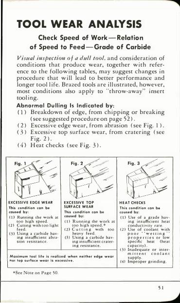
Visual inspection of a dull tool, and consideration of conditions that produce wear, together with reference to the following tables, may suggest changes in procedure that will lead to better performance and longer tool life. Brazed tools are illustrated, however, most conditions also apply to "throw-away" insert tooling. Abnormal Dulling 15 Indicated by: ( 1 ) Breakdown of edge, from chipping or breaking
( see suggested procedure on page 52 ) . ( 2 ) Excessive edge wear, from abrasion ( see Fig. 1 ) . ( 3 ) Excessive top surface wear, from cratering ( see
Fig. 2 ) . ( 4 ) Heat checks ( see Fig. 3 ) .
EXCESSIVE EDGE WEAR
This condition can be caused by:
( 1 ) Running Ihe work at 100 high speed.
( 2 ) CUlling wilh 100 lighl feed.
( 3) Using a carbide hav· ing' insufficient abrasion resistance.
EXCESSIVE TOP SURFACE WEAR
This condition (on be caused by:
( 1 ) Running the work at 100 high speed. *
( 2 ) C U l l i n g wilh 100 heavy feed.
(3) Using a carbide having insufficient cratering resistance.
Maximum tool life is realized when neither edge wear no, top surfoce wear is .xcessive.
*See NOle on Page 50.
HEAT CHECKS
This condition (on b. co used by:
(1) Use of a grade having insufficient heat conductivity rate.
(2) Use of coolant wilh p o o r ' ' w e ( ( i n g " p r o p: e c t i e s or low speCific heat (heat capacity) .
( 3) Inadequate or interm i n e o r c o o l a n t supply.
(4) Improper grinding.
5 1
CHECK OF CA RBIDE G R A D E : Use th e one m ost suitable for the job. Kennametal metal-cutting Grades are classified into four general types of carbide. with different degrees of hardness in each. ( See pages 29 through 32. )
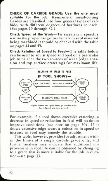
Check Speed of the Work-To ascertain if speed is within the proper range for the hardness of material being machined it should be checked with the table on pages 44 and 45. Check Relation of Speed to Feed-The table below can be used to adjust speed and feed on a particular j ob to balance the two sources of wear (edge abrasion and top surface cratering) for maximum life.
IEUTIOI OF SPEU TO FEU I F TOOL SHOWS-
EXCESSIVE EDGE WEAR
Higher Speed! and lighler feed, go IOQerher 01 do lower Speed, and Heayier Feeds
For example, if a tool shows excessive cratering, a decrease in speed or reduction in feed will no doubt improve conditions ( see note on page 50 ) . If it shows excessive edge wear, a reduction in speed or increase in feed may remedy the trouble.
This table, however, provides for adjustment within the limits of a single carbide grade only, and further analysis may indicate that additional improvement in tool life can be obtained by changing to a grade that is more suitable for the job in question-see page 33.
5 2
Kendex Too l Care
The ever-increasing use of Kendex indexable insert tooling eliminates many potential sources of tool trouble as encountered with brazed tools. The mechanical tool, however, must be used correctly and maintained in good working order if it is to provide maximum efficiency. The following check list will help keep such tools working.
1. Use the correct insert. 2. Use the most effective chip breaker.
3. Replace damaged shims. 4. Keep the insert recess clean. 5. Replace bent or cracked clamps. 6. Check holder carefully after an accident. 7. Do not "over-run" inserts. 8. Do not over-wrench clamping screw.
9. Select the most suitable holder for the job. 1 0. Mount holder rigidly with mi nimum over
hang. 1 1 . The holder can be damaged-don 't try to
prove it!
Probably one of the most common causes of tool trouble with indexable insert tooling is the continued use of a holder that has been damaged in an accident. A broken or badly chipped shim cannot provide the support needed for good performance. In addition, serious smashups sometimes damage one or both of the supporti ng back walls of the holder. This condition usually cannot be repaired satisfactorily and a new holder will undoubtedly prove to be the least costly solution.
5 3
To assure proper use of Kendex holders, and tools in general, requires only two or three precautions.
1. Change the insert before it breaks. Running an insert for "j ust a few more" pieces is hazardous.
2. Clean the recess, shim, chip breaker, and insert on each i ndex. Dirt in the recess or pocket or work material welded to the insert or chip breaker result in poor seati ng-th is will cause trouble.
3 . Seat i nsert securely and tighten clamp moderately. When replacing the insert in the holder make sure it seats firmly, so that it does not "rock" i n a n y direction.
U se only the wrench intended to tighten the clamp. Wrench extensions are nOt needed.
Observance of these principles in the use, operation, and maintenance of Kendex holders will provide long life, efficient performance, and maximum economy.
Brazed Tool Care Although brazed tools have been replaced by
Kendex tools on many operations, there are numerous machining jobs which can be done economically with brazed tools. The general principles regarding care of Kendex tools also apply to brazed tools. The following hints will aid in avoiding trouble.
5 4
1 . Select the most suitable tool. 2. Mount it rigidly with minimum overhang. 3. Do not permit excessive wear to develop. 4. Exercise good grinding practice when recon
ditioning. 5. When brazing, follow recommended proce
dures.
GRINDING TOOLS General Instruct ions
Although Kennametal compositions are extremely hard, no difficulty need be experienced in grinding Kennametal single-point tools when proper grinding procedures are followed.
The essential requirement is to avoid "thermal shock " caused by a sudden change in temperature. The greatest possibility of thermal shock is in brazed tools due to the difference in expansion rates of carbide and steel. When crater resistant grades o f carbide are heated, they expand about one-half as much as steel. The wear resistant grades expand one-third as much as steel. Therefore, a brazed tool is already strained and grinding heat may cause failure.
A dull brazed tool can be res harpe ned several times by simply touching up on a fine grit diamond wheel. Only the tip need be ground. However, a tip that has been chipped or broken requires extensive grinding of both steel and carbide and a tool may be damaged in one of two ways:
1. If the surface of the carbide is overheated, while the interior remains comparatively cool, unequal expansion will cause "crazing"-a network of hairline cracks or checks on the surface.
2. If the steel is overheated while carbide remains comparatively cool, as when grinding away the shank below the tip, heat cracks will develop.
This manual gives only general information on tool grinding. For detailed procedure refer to publications available from grinding wheel manufacturers such as "Grinding Carbide Tools" published by the Norton Company.
5 5
,...
Offhand Grinding
Use of proper Grinding Wheels is extremely important. Medium bond silicon carbide wheels. 46 to 60 grit for roughing and 90 to 1 20 grit for finishing, are generally recommended . Alumi num oxide wheels are suitable for rough grinding the shank steel below the tip but care must be taken to avoid grinding the tip or overheating the steel.
Diamond cup wheels of 100 to 220 grit, resinoid or vitrified bonds, are generally used for offhand finish grinding of carbide cutting tools. Metal-bond wheels are normally slower in their cutting action but are more durable and the face of the metal bond wheel will remain flat and true much longer than either the resinoid or vitrified bond types.
FoJlow the recommendations of your wheel manufacturer as to suitability of wheel for your purpose and method of dressing.
Wet Grinding The use of wet grinding for roughing of steel
shanks and silicon carbide grinding of parts made from Kennametal is recommended to minimize the possibility of overheating. Wet grinding usually allows the use of a more durable wheel, it is faster than dry grinding and reduces the abrasive dust condition.
A fluid specially compounded for carbide grinding is generally satisfactory. Many suitable compounds are available. The coolant should flow liberally onto the wheel and cover the entire working surface of the tool. I ntermittent or insufficient flow may produce alternate heating and quenching of the tool and cause tip to crack due to temperature changes.
56
Regrinding Procedure
A considerable saving in carbide, as well as in grinding wheels, can be made by regrinding tools more frequently. If possible, have a regular schedule for regrinding tools after a certain number of pieces have been machined or after the tools have been used over a definite period of time. Do not put off regrinding until the cutting edge is chipped or broken. Some plants consider a roughing tool too dull when it shows approximately O.030-inch edge wear land. Wear land on finishing tools should not be much greater than the feed. Resharpening a normally-dulled tool requires only a small amount of grinding with a diamond wheel to provide a sharp cutting edge.
How to Avoid Grinding Cracks Cracks caused by faulty grinding practices are of
two types and both result from "thermal shock." They are:
1. "Crazing" or minute checks on the tip from sudden heating of the surface.
2. Larger cracks from heating of the tip a nd shank, usually parallel to the braze joint.
Crazing-This is caused by raising the temperature of the surface of the tip too rapidly (for a depth of about O.O l O-inch) to a high temperature, thereby creating a marked difference in the rate of expansion between the surface and the comparatively cool interior of the tip.
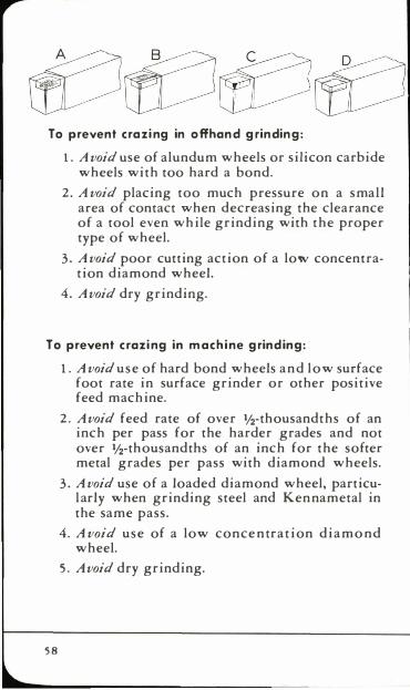
The high surface strain results in many fine cracks, often visible only under a powerful magnifying glass after the tip is lightly sand-blasted, or wet blasted, as shown in sketch A.
5 7
,..
To prevent cra zing in offhand grinding:
1 . A void use of alundum wheels or silicon carbide wheels with too hard a bond.
2. A void placing too much pressure on a small area of contact when decreasing the clearance of a tool even while grinding with the proper type of wheel.
3. A void poor cutting action of a low concentration diamond wheel.
4. A void dry grinding.
To prevent crazing in mach ine grind ing:
5 8
1. A void use of hard bond wheels and low surface foot rate in surface grinder or other positive feed machine.
2. A void feed rate of over 1f2-thousandths of an inch per pass for the harder grades and not over 1f2-thousandths of an inch for the softer metal grades per pass with diamond wheels.
3. A void use of a loaded diamond wheel, particularly when grinding steel and Kennametal in the same pass.
4. A void use of a low conce ntration diamo nd wheel.
5. A void dry grinding.
A tool crazed on the broad top surface of the tip will sometimes lose a section back of the cutting where there is apparently no strain, as shown i n sketch B.
A crazed tip surface may also develop along the side of the cutting edge as shown in sketch C. The breaks run straight down and occur when the tool is cutting, as though from too high pressure.
Heat Cracks-The second and larger type of crack in a tool tip is more easily seen. It usually appears near to, and parallel with, a brazed surface as shown in sketch D. Or it may start at the edge of a tip, then swing around parallel to the braze. This type of crack is caused by:
1. Unequal expansion of steel and carbide which can be caused by overheating the shank while the tip remains cool. This often occurs when steel is being snagged away beneath the tip.
2. Rapid cooling after grinding.
3. An interrupted flow of coolant which allows the tool to heat up while cutting and then to be suddenly quenched when the flow of coolant is restored.
Whenever a tool shank is blue below the tip from the heat of grinding, a crack of this type will probably be found in the tip. However, the crack may not become apparent until the tool is in use. Such cracking can be prevented by careful wet grinding.
5 9
,..
CHIP CONTROL Chip control and disposal present no great prob
lem on jobs involving irregular or interrupted cuts, or brittle materials. as the chip will break up without mechanical assistance.
However, when machining tough, stringy materials which cut with a continuous chip, a chip breaker is desirable to coil the chip or break it up into relatively short lengths for easy disposal. A properly directed flow of coolant also helps break the chip coil and helps wash the chips into the pan.
Kendex Chip Breaker Plates On mechanically-held insert type tools, such as
Kendex tooling, a separate chip breaker plate of hard carbide is used. Proper chip control can be obtained by varying the distance between the chip breaker plate and the cutting edge. The chip should be broken in the largest possible coils to keep cutting pressures to a minimum.
A solid Kennametal chip breaker plate for use on the Kendex tools provides ideal chip control and eliminates expensive chip breaker grinding. This mechanical chip breaker has a wide range of application as shown in the illustration where the same chip breaker was used at 0.0 1 4 and 0.036-inch feed to provide effective chip control. Kenloc inserts with preformed chip grooves are available for general machining operations.
60
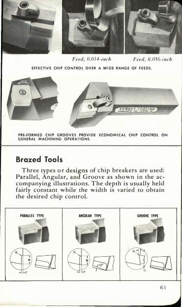
Feed, 0.0 14-inch Feed, O.036-inch EFFECTIVE CHIP CONTROL OVER A WIDE RANGE OF FEEDS.
KFND£% rOCUING ,'MII'.,I,.,,,,, '''' ... tAUt",.' ,#
PRE-FORMED CHIP GROOVES PROVIDE ECONOMICAL CHIP CONTROL ON GENERAL MACHINING OPERATIONS.
Brazed Tools Three types or designs of chip breakers are used:
Parallel, Angular, and Groove as shown in the accompanying illustrations. The depth is usually held fairly constant while the width is varied to obtain the desired chip control.
PARAIllL TYPE ANCULAR TYPE CRooVE TYPE
6 1
Grinding Chip Breakers
BRAZED TOOLS Chip breaker grooves should be ground on a sur
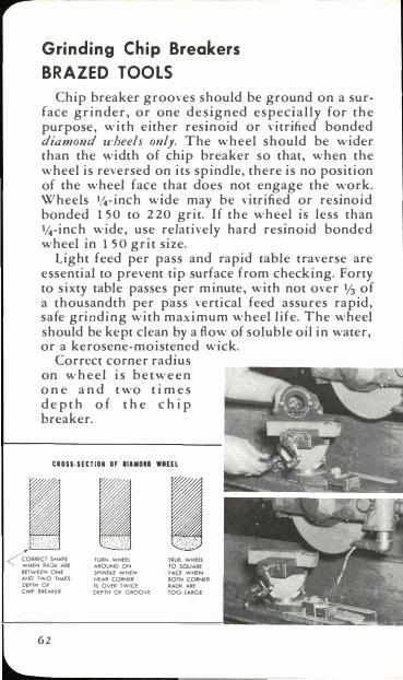
face grinder, or one designed especially for the purpose, with either resinoid or vitrified bonded diamond wheels only. The wheel should be wider than the width of chip breaker so that, when the wheel is reversed on its spindle, there is no position of the wheel face that does not engage the work. Wheels II4-inch wide may be vitrified or resinoid bonded 150 to 220 grit. If the wheel is less than Ikinch wide, use relatively hard resinoid bonded wheel in 150 grit size.
Light feed per pass and rapid table traverse are essential to prevent tip surface from checking. Forty to sixty table passes per minute, with not over Y3 of a thousandth per pass vertical feed assures rapid, safe grinding with maximum wheel life. The wheel should be kept clean by a flow of soluble oil in water, or a kerosene-moistened wick.
Correct corner radius on wheel is between o n e a n d t wo t imes depth o f t h e chip breaker.
CROSS·SEeTIOR OF DlaMOIl WMEn
CORRECT SHAPE WHEN !tA:lIj ARE
BflWffN ONE
ANO TWO TIMES
DEPTH Of
CHIP BREAlCfR
6 2
TURN WHEEl AROUND ON SPINDlE WHEN NEAR CORNU
IS OVER TWICE DEPTH Of GROOVE
rRUE WHEEl TO saUARE f .... CE WHEN
BOTH CORNEll RADII AilE
TOO LARGE
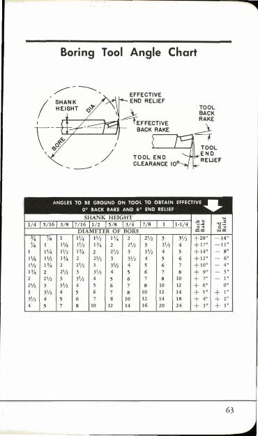
Yo 1 1 1 ',4 1',4 1'1, I'/' 1% 1% 2 2'1, 2'1, 3 3 3'/, 3'/, 4 4
Boring Tool Angle Chart
- ---
1 ',4 1'/, 1% 1'1, 1% 2'/, 1% 2 2'1, 3 2 2'/, 3 3'1, 2'/, 3 3'/, 4 3 3'/, 4 3'/, 4 5 4 6
7 8 10 12
EffECTIVE END RELIEf
2'/, 3'/, 3 3'/, 4 3'1, 4 4
10 10 12
10 12 14
14 16 20
10 12 14 IS 24
TOOL E N D REUEF
+ 17· - 1 1 ·
+ 14· - S·
+ 12· - 6·
+ 10· - 4·
+ 9° - 3 ·
+ 7° _ 1 °
+ 6° 0°
+ 5° + 1 ·
+ 4° + r + 3° + 3°
63

,..
For Additional Help The suggestions contained in the foregoing pages
are based on years of experience in the development and application of Kennametal to a wide variety of metalworking problems. They cover the situations most frequently encountered in customary machining operations.
Naturally, conditions will vary in different shops and on different jobs, and certain unusual problems not covered in this manual will arise from time to time. Some of these problems are adequately covered in other Kennametal publications, which we will be glad to send you at your request. For others, Kennametal engineers will help you work out the best possible methods for using our products.
Call on us when you need further information or assistance.

SA·20 ( 15 ) L7 Printed in U.S.A.

KENNAMETAL INC. LATROBE, PA. 15650
KfMNAMfTAl
�--- . - " - - , ,.- -