keith v-9 v-floor drive installation manual original ... v-9 v-floor... · 4.2 sub-deck profiles...
TRANSCRIPT

1
©2018 KEITH Manufacturing Co. All Rights Reserved. KEITH, KEITH logo and WALKING FLOOR are registered trademarks of KEITH Manufacturing Co. Equipment manufactured by KEITH Manufacturing Co. is protected by numerous patents both domestic and foreign.
Revised: 09.18.18
KEITH® V-9 V-FLOOR® Drive Installation ManualOriginal Instructions
www.KeithWalkingFloor.com
KEITH Mfg. Co.World Headquarters800-547-6161541-475-3802541-475-2169 fax

2
TABLE OF CONTENTS V-FLOOR® Installation
1 INTRODUCTION
2 TRAILER PREPARATIONS 2.1 Drive unit compatibility 2.2 Trailer alignment 2.3 Bracing 2.4 Hydraulic tubing locations 2.5 Cross-members
3 DRIVE UNIT 3.1 Center frame trailer 3.2 Frameless trailer 3.3 Painting
4 SUB-DECK 4.1 Baffleplate 4.2 Sub-deckprofiles 4.3 End sub-deck 4.4 Side seal options 4.5 Retainer clips 4.6 J-bearing 4.7 Drive channel
5 FLOORING 5.1 Floor slats 5.2 Slat installation 5.3 Front shield
6 HYDRAULIC TUBING
7 MISCELLANEOUS 7.1 Wires and lines 7.2 Caution decals 7.3 Front guard
Appendix 1 Tools Appendix 2 Materials Appendix 3 Reference drawings Appendix 4 Check list Appendix 5 Torque chart

3
1 INTRODUCTION V-FLOOR® Installation
This manual explains procedures for installing the KEITH® V-FLOOR® unloading system. Many variables affect the installation, but the general process remains constant. Details of the installation vary according to trailer features, kit selections, and installer preferences. Optional sets of instructions are given for some operations to allow for flexibility.
This manual focuses on the installation of a 6” stroke, 9-slat system on 10.5” slat centers. Installation of the system with 10” slat centers is similar. Information unique to 10” slat centers is included where it pertains. Installation time varies and is between 35 and 100 hours, depending upon the experience of the installer and the adaptability of the trailer. If the trailer is not yet built, there are some trailer preparations found (Chapter 2) that will save time and effort. One person with welding skills can complete the entire installation.
Anefficientinstallationrequiresappropriatetoolsandaccessiblematerials.Alistoftools is found in Appendix 1. Appendix 2 lists materials. Several reference drawings accompany this manual. The KEITH Running Floor II owner’s manual contains more detailed information about the system and operation procedures.
DirectanyquestionstoKEITHMfg.Co.oroneofourinternationalofficeslistedonthecover of this manual.
WARNING: Installing the WALKING FLOOR® system will require some alterations to your trailer. Changes made without approval of the trailer manufacturer may void the trailer’s warranty.

4
2 TRAILER PREPARATIONS V-FLOOR® Installation
The trailer requires preparation before the system is installed. Planning ahead for the WALKING FLOOR®installationrequirementssavessignificantpreparationtime,especially when building a new trailer.
2.1 Drive unit compatibility
There are two styles of drive units. The trailer’s frame determines which style should be used. Check the compatibility of the drive unit with the trailer before making any alterations to the trailer.
If the frame rails extend the full length of the trailer (Figure 1), use a drive unit without frame rails (Figure 2).
If the trailer is “frameless” (Figure 3), use a drive unit equipped with tapered frame rails (Figure 4).

5
2 TRAILER PREPARATIONS V-FLOOR® Installation
NOTE: Manufacturers of frameless trailers may want to consider extending their axle rails far enough forward that a frameless drive unit can be installed (extend 109” for 6” stroke).
Chapter 4 discusses the drive unit installation process in more detail.
2.2 Trailer alignment
1. Adjust the trailer to meet these conditions:
A) The trailer must be straight to allow for proper parallel movement of the slats.Determinestraightnessbysightingdownafloorslatpositionedin the trailer.

6
2 TRAILER PREPARATIONS V-FLOOR® Installation
B) The cross-members on which the sub-deck mounts must be level, because the friction based principle of the WALKING FLOOR®systemrequiresaflatfloor.If there are deviations exceeding 1/8”, make corrections. Ensure that the last beam of the trailer at the rear door threshold is level with the cross members.
2.3 Bracing
Trailer bracing prevents warping.
1. Install bracing as shown in Figures 5 and 6. Itisbesttoaddbracingbeforeremovingtheoldfloorbecausethefloorkeeps thetrailerstraight.Ifflatbarisused,makeacross-bracingbecauseitwillbuckle easily under compression. Steel angle does not require a cross. Make sure there is enough wheel clearance when installing steel angle. The bracing reaches to the drive opening. Weld or bolt the braces to each intersecting cross-member.
2.Removeoldflooring.
2.4 Hydraulic tubing locations
Figure 5
Figure 6
1. AXLE FRAME2. LANDING GEAR FRAME3. BRACES

7
2 TRAILER PREPARATIONS V-FLOOR® Installation
Hydraulic pressure, generated by the tractor’s wet kit, powers the drive unit. Tubing must connect the drive unit to the tractor.
1. Consider the location of the hydraulic tubing. Chapter 6 provides more information on this subject. A central location is preferable for the quick-couplers in front of the trailer. This keeps hose lengths short, if they stay connected while driving.
There are four options available:
1) Routing the hydraulic tubing through the cross-members (Figure 7). Make two 1 3/8” holes per cross-member. The holes should be close to the sides of the trailer to maintain the structural integrity of the cross-members. Access holes must be cut or drilled through the nose of the trailer, in line with where the tubes will pass through cross-members. Patch the holes after the tubing is in place. The tubes may drop below the cross-members anywhere behind the landing gear and attach to the under side of cross-members.
2) Routing the tubes under the side seal (Figure 8). Check the available space underneath the side seal. One tube may occupy each side of the trailer. Tubes are clamped to cross-members or placed in 1” inside diameter PVC pipe to prevent rubbing. The side seal should be detachable for maintenance.
Figure 7

8
2 TRAILER PREPARATIONS V-FLOOR® Installation
3) Routing the tubing underneath the cross-members. This option is not recommended, as it can cause problems with truck tire clearance and it makes the tubing very vulnerable.
2. Make sure that brake lines and electrical wires will not interfere with moving parts. If necessary, reroute them to protect them from damage.
2.5 Cross-members
Cross-members function as support for the sub-deck.
Compare the trailer cross-member height to the formed cross sills on the drive unit. They should be the same. If they differ, contact KEITH Mfg. Co. or one of our international offices.
1. Remove cross-members to create an adequate gap for the drive unit (Figure 9). See Chapter 3 for more information about drive unit location.
2. Reposition cross-members if necessary.The rearmost cross-member should be mounted a minimum of 17” inside the trailer doors. The foremost cross-member should be about 17” away from the front wall.
Figure 8
Figure 9

9
3 DRIVE UNIT V-FLOOR® Installation
NOTE: Holes for the hydraulic tubing should be made through cross-members before they are mounted on a new trailer.
3 DRIVE UNIT
Drive unit installation in a center frame trailer differs from an installation in a frameless trailer. Chapter 3 examines the two installations separately.
3.1 Center frame trailer
1. Decide on the location of the drive unit.The drive unit should be installed as close to the rear of the trailer as is practical.
2. Mark a centerline from rear to front of trailer. This will be used to align drive and sub-decking.
3. Position drive unit.The drive should be positioned and welded, before the sub-deck is installed. The system can be lifted into an open top trailer from above with a crane. (Figure 20)
10
3 DRIVE UNIT V-FLOOR® Installation
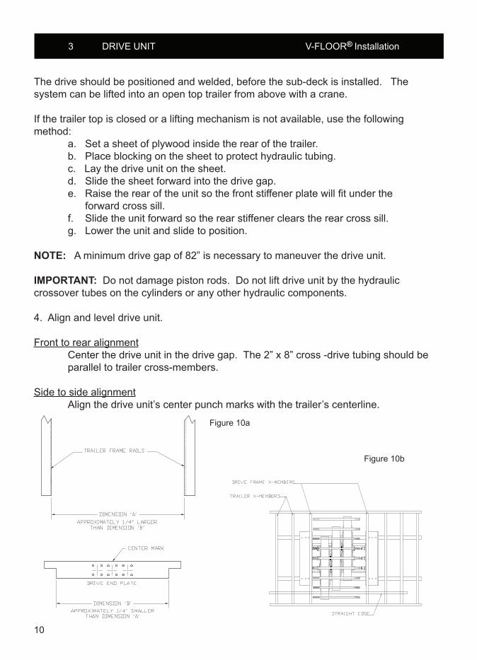
The drive should be positioned and welded, before the sub-deck is installed. The system can be lifted into an open top trailer from above with a crane.
If the trailer top is closed or a lifting mechanism is not available, use the following method: a. Set a sheet of plywood inside the rear of the trailer. b. Place blocking on the sheet to protect hydraulic tubing. c. Lay the drive unit on the sheet. d. Slide the sheet forward into the drive gap. e.Raisetherearoftheunitsothefrontstiffenerplatewillfitunderthe forward cross sill. f. Slide the unit forward so the rear stiffener clears the rear cross sill. g. Lower the unit and slide to position.
NOTE: A minimum drive gap of 82” is necessary to maneuver the drive unit.
IMPORTANT: Do not damage piston rods. Do not lift drive unit by the hydraulic crossover tubes on the cylinders or any other hydraulic components. 4. Align and level drive unit.
Front to rear alignment Center the drive unit in the drive gap. The 2” x 8” cross -drive tubing should be parallel to trailer cross-members.
Side to side alignment Align the drive unit’s center punch marks with the trailer’s centerline.
Figure 10b
Figure 10a
11
3 DRIVE UNIT V-FLOOR® Installation
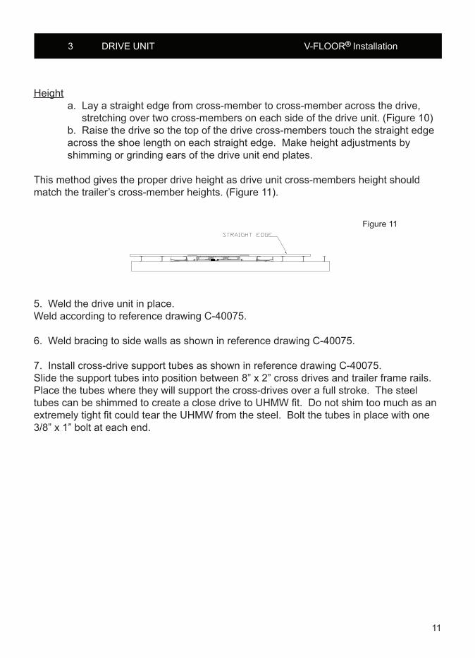
Height a. Lay a straight edge from cross-member to cross-member across the drive, stretching over two cross-members on each side of the drive unit. (Figure 10) b. Raise the drive so the top of the drive cross-members touch the straight edge across the shoe length on each straight edge. Make height adjustments by shimming or grinding ears of the drive unit end plates.
This method gives the proper drive height as drive unit cross-members height should match the trailer’s cross-member heights. (Figure 11).
5. Weld the drive unit in place. Weld according to reference drawing C-40075.
6. Weld bracing to side walls as shown in reference drawing C-40075.
7. Install cross-drive support tubes as shown in reference drawing C-40075. Slide the support tubes into position between 8” x 2” cross drives and trailer frame rails. Place the tubes where they will support the cross-drives over a full stroke. The steel tubescanbeshimmedtocreateaclosedrivetoUHMWfit.DonotshimtoomuchasanextremelytightfitcouldteartheUHMWfromthesteel.Boltthetubesinplacewithone3/8” x 1” bolt at each end.
Figure 11

12
3 DRIVE UNIT V-FLOOR® Installation
3.2 Frameless trailer
NOTE: Manufacturers of frameless trailers may want to consider extending their axle rails far enough forward that a frameless drive unit can be installed (extend 109” for 6” stroke).
1. Position drive unit in the drive gap. Checktobesuredriveunitdimensionsfitthelocation.Therailheightsshouldbe close, (Figure 12) and dimension A should equal dimension B (Figure 13). The system can be lifted from above with a crane or from below with a forklift. Raise the tapered drive frame rail tight against the bottom of the cross sills.
IMPORTANT: Do not damage piston rods. Do not lift drive unit by the hydraulic crossover tubes on the cylinders or any other hydraulic components.
NOTE: Exact alignment of trailer centerline with the drive unit centerline is more important than alignment of the drive unit frame with the trailer’s axle beams.
Figure 12

13
3 DRIVE UNIT V-FLOOR® Installation
Figure 13
2. Align and level drive unit. The ends of the formed cross sills should rest on the trailer side rails.
Front to rear alignment Butt the tapered drive frame rails tight against the ends of the axle beams (Figures 14 and 15). A transfer plate may be placed between the two beams if a flatsurfacedoesnotexistoneitherthedriveframeortheaxlebeam.
Side to side alignment Align the drive unit’s center punch marks with the trailer’s centerline. (Figure 14)
Figure 14

14
4 SUB-DECK V-FLOOR® Installation
Height (Figure 15) a. Lay a straight edge from cross-member to cross-member across the drive, stretching over two cross-members on each side of the drive unit. b. Raise the drive so the top of the drive cross-member touches the straight edge across the shoe length on each straight edge. Raise or lower the drive unit accordingly .
3. Weld the drive unit in place. Weld according to reference drawing C-10797A
4. Weld bracing to side walls as shown in reference drawing C-10797A.
3.3 Painting
The factory paints drive units with gray oxide primer.
1.Confirmthatthedriveunitiscoatedwellwithprimer.
2.Treatthedriveunitandsub-deckwithafinishingpaint.
IMPORTANT: Make sure that the following parts are protected when painting: cylinder chrome rods, switching valve chrome rod, serial plate and any decals.
4 SUB-DECK
Thesub-deckisthestructuredirectlyabovethecross-membersandunderneaththefloorslats.Thesub-deckconsistsofaluminumprofiles.Thealuminumprofilesmountontopof the cross-members.
Figure 15

15
4 SUB-DECK V-FLOOR® Installation
4.1 Baffle plate
Abaffleplateextendsforwardfromthedoorthresholdtopreventmaterialfromsiftingthroughthefloorwhenslatsareintheforwardposition.
1.Determinethedimensionsofthebaffleplate(Figure16). Thebaffleplatemustbelevelwiththecross-membersandisweldedtotheinside of the last beam of the trailer (threshold). The thickness depends on the type of load. For light materials (e.g. sawdust), use 12 gauge. ¼” is recommended for heavy, abrasive materials (e.g. solid waste). The plate bends down inside the closed door, leaving an opening so that material will not build up underneath theslats.Forfinematerials,thebaffleplateconnectstothenearestcross- member to prevent material from sifting through. Holes may be cut in the plate toletsmallamountsoffinematerialdropthrough.Thispreventsbuildupfrom exerting upward pressure on slats.
2.Cutandformthebaffleplatetotheproperdimensions.3.Installthebaffleplate. Weldtheplateinposition.Thengrindweldsflat.Makesureitislevelwiththe cross-members.
Figure 16

16
4 SUB-DECK V-FLOOR® Installation
4.2 Sub-deck profiles
Theproperinstallationofthealuminumprofilesiscriticalformaintainingdrivealignment,floorstraightnessandforoptimalperformanceofthebearinglocatedunderthefloorslats. Sub-decking is applied after the drive unit is positioned
Position and mount the sub-deck.
Sub-deckon10.5”centersisfor10.5”slatcenterflooring(Figure17).Sub-deck on10”centersisfor10”slatcenterflooring(Figure18).
Start at the rear of the trailer. Lay out the sub-deck in the trailer and separate them with spacing jigs, aligning the centerline mark on the jigs with the centerline mark on the cross-member. Keeping the jigs above the cross-members, clamp the jig and sub-deck to every other cross-member. Sub-decking should start 11” inside the rear door and end 6” from the front wall (Figure 19).
Figure 17
Figure 18
Figure 19

17
4 SUB-DECK V-FLOOR® Installation
Weld or bolt the sub-deck to the cross members between the jigs. Move the jigs and make a connection at each intersection of a piece of sub-decking and a cross-member. Weldsshouldbe1/8”fillet,3/4”to11/4”long,andcenteredontheflange.Excessivewelding and too little cooling will cause cross-members to warp (Figure 20).
Figure 21 suggests a welding pattern. Starting each pass on the same side of the trailer givessufficientcoolingtime.
See Figures 22 & 23 for welded and bolted sub-deck details. Mylar tape or paint should separatealuminumprofilesfromsteelcross-memberstopreventmetaldecay.
Figure 20
Figure 21
Figure 22
11”

18
4 SUB-DECK V-FLOOR® Installation
Figure 23
4.3 End sub-deck
There are two end sub-deck options for the discharge end of the trailer.
1) Weld on cap. The weld on cap needs to be installed before the slats or the J-bearings. This cap is used to keep material from entering under the sub-decking and also holds the bearings in place. Place cap against sub-deck on discharge end of trailer. The cap shouldbepre-cutintheprofiletomatchthesub-deckingandside-sealpieces (Figure 24).
Figure 24

19
4 SUB-DECK V-FLOOR® Installation
2) Tail end supports. Tail end supports are an option used to support the ends of the slats when heavy loads could damage or bend the slats down during unloading, e.g. crushed car applications.
Note:Tailendsupportsneedtobeaddedafterthefloorslatsareinstalledtoensureproper installation height. One support is used to support each slat.
a. Attach wear plate to bottom of slat using position and weld detail (Figure 25).
b. Place wear plate support assembly under wear plate, attached to the bottom ofthefloorslat.Makesurethatthetwofacesofthehardenedwearplatesarein contactandweldtheformedanglemountstothe45°slopedbaffle.
Figure 25
Figure 26

20
4 SUB-DECK V-FLOOR® Installation
c. Weld the formed angle mounts to the support assembly, making sure that the wear plates are in contact (Figure 27).
4.4 Side seal options
The side seal incorporates the trailer walls to the two outside pieces of sub-decking (also knownassidesealsub-decking).Thecorrectquantityandsidesealprofilesaresuppliedwith your kit.
The side seal material will match the material of the trailer walls. For example, an aluminum walled trailer will use aluminum side seal.
Some of the side seal options are shown on the following page.
Figure 27
Figure 28

21
4 SUB-DECK V-FLOOR® Installation
Figure 29
Side seal should span the entire length of the sub-deck. One section of each side may need to be cut, as side seal comes in 12’ lengths for steel and 10’ lengths for alumimum.
1. Place side seal in trailer. Steel side seal should be no less than 3/16” from the edge of the sub-deck. Either weld or bolt side seal to outside piece of sub-deck (Figure 30).
Note: Make sure ½” aluminum sub-deck cap is welded into place at end of sub-deck before attaching side seal.
2. Weld the full-length of the side seal to the trailer wall. This should be done with several skip welds to keep from concentrating the heat in one area. The full- length weld will keep material from getting behind the side seal and separating it from the wall.
Figure 30

22
4 SUB-DECK V-FLOOR® Installation
4.5 J-bearing
The“J”-shapedbearingsupportstheflooringandcreatesabearingsurfacesothatthereisnometal-to-metalcontactbetweentheflooringandsub-deck.TheJ-bearingwillneedto be 6” shorter than the sub-deck to allow for expansion with the temperature changes. Each slat will be supported by two pieces of bearing.
1. Cut J-bearing 6” shorter than the length of sub-decking.
2. Using a dead blow hammer and starting at the front of the trailer, attach one bearing on each side of a piece of sub-decking. Note that the bearing needs to start 6” from the end of the sub-deck to allow room for expansion. Hammer on the bearings, only 1’ to 2’ by hand (Figure 39).
Figure 31

23
4 SUB-DECK V-FLOOR® Installation
3. Install the J-bearing the full-length, using the provided roller tool. Place the tool over the sub-decking and bearing from the front of the trailer. The wider roller spacing needs to face the discharge end of the trailer.
Note: If the front wall of the trailer is already installed, there may be limited room to insert the roller tool between the wall and the sub-decking. The roller tool may need to be slid up from the rear of the trailer to the front wall before placing the J-bearing onto the sub-deck.
4. Tap the roller tool toward the rear of the trailer using a mallet, installing the bearing 1’ to 2’. Check to ensure that the bearing is fully installed on the sub-deck. Ifthebearingisnotfullyinstalledtightlyontothesub-deck,theslatwillbedifficult to install and could increase operating pressures. Adjust the tool, if needed, to ensure proper installation of the bearing.
5.Afterthetoolisadjustedcorrectly,weldapieceofsteelflatbartoeachendof the tool so that it holds the adjustment. The tool should only need to be adjusted once.
6. Use a forklift or winch with a steel cable to pull the tool to the rear of the trailer, installing the bearing full-length. Repeat these steps to install the bearing on each piece of sub-deck. Periodically check to ensure that the bearing is being fully installed onto the sub-deck.
7. The roller tool will not work to install the outside pieces of J-bearing onto the side seal sub-decking. These need to be hammered on, full-length.

24
4 SUB-DECK V-FLOOR® Installation
4.6 Securing J-bearing
Drill Jig (P/N 8270302)
1. Clamp the drill jig (P/N 8270302) in place and drill pilot holes through the J-bearing and sub-deck using the drill template jig and a ¼” (6.4mm) drill bit. Lubricating the drill bit with aluminum cutting oil between drilling holes will minimize broken bits.
Drill Jig: Front View
Figure 32
Figure 33

25
4 SUB-DECK V-FLOOR® Installation
Drill Jig Application
2. Remove the jig and countersink these holes with a 90° bit. Install (6) 1/4” x 1-1/4” FHCS TORX F ZINC countersunk FH Rolok® screws (KEITH P/N 87701593) at the discharge end of each subdeck insert. Install (4) 1/4” x 5/8” FHCS TORX TYPE F ZINC countersunk FH Rolok® screws (KEITH P/N 87701592) at the discharge end of each piece of J-bearing. Use Loctite thread retainer #243 (KEITH P/N 87103202) or equivalent.Besuretheheadsofthescrewsareflushorjustbelowthesurfaceofthebearing. This secures the bearing in place.
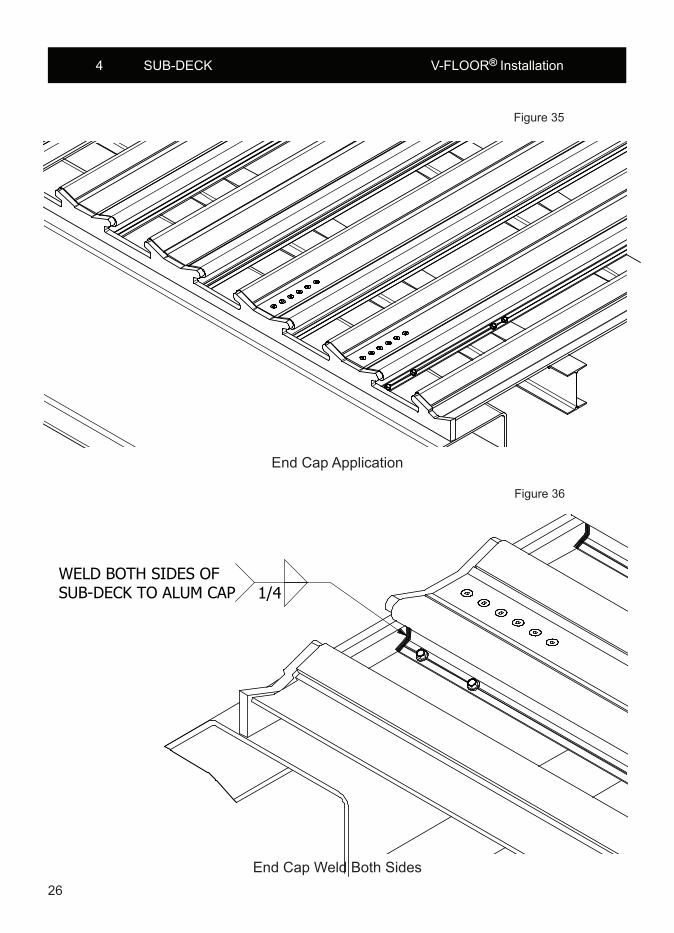
3. Weld end caps onto the discharge end of sub-deck and side seal sub-deck (see weld detail). These caps plug the sub-deck cavities and ensure the bearing can’t slide out of the rear of the trailer. Make sure no weld is higher than the top surface of the J-bearing.
Figure 34
1/4” x 5/8” screwsP/N 87701592
1/4” x 5/8” screwsP/N 87701592
1/4” x 1-1/4” screwsP/N 87701593
26
4 SUB-DECK V-FLOOR® Installation
End Cap Application
End Cap Weld Both Sides
Figure 35
Figure 36

27
4 SUB-DECK V-FLOOR® Installation
4.7 Drive channel
Thedrivechannelistheconnectionbetweentheflooringandthecross-drives.Analuminumchannelisusedforaluminumfloorslatsandsteeldrivechannelforsteelslats.
1. Set the drive channels onto the cross-drive shoes so that the legs of the channel are facing up. Place the tapped nut bar on, aligning the slots in the drive channel. Use two 3/8” x 2” hex bolts on each side to attach the drive channel to the drive shoe (Figure 34). Only use two bolts, because they are only for setup and will be removed.
Note: Do not tighten bolts. The drive shoe should be able to slide side-to-side in theslotstoallowalignmentwiththeflooring,wheninstalled.
Figure 37

28
5 FLOORING V-FLOOR® Installation
5 FLOORING
5.1 Floor slats
1.Determinelengthoffloorslats. The slats have to reach from 1” from the doors to a minimum of 9”-- for a 6” stroke system--fromtheclosestpointonthefrontwallatfloorlevel.Thisimpliesthat the maximum length of the slats is 10”-- for a 6” stroke system-- shorter than the inner length of the trailer. For example, maximum slat length for a 6” stroke unit in a 45’ trailer is 44’-2”.
WARNING: Make sure that the slats do not bump the front wall; watch for round shaped walls. Be particularly careful with bull nosed trailers.
2.Cutfloorslatstolength. Ifawearplateismountedononeendofthefloorslat,cutthesurplusoffatthe opposite side.
NOTE: KEITH Mfg. Co. normally performs steps 1-2.
5.2 Slat Installation
Slat installation is the same for all types of slats, in all widths. Make sure all cylinders are collapsed toward the discharge end. The cylinders need to be blocked to keep them from moving when the slats are slid into place.
1. Slide slats into trailer, so that the ears on the bottom of the slat slide underneath the J-bearing, keeping the slat from lifting up. The slats need to end 1” inside the door, with the cylinders collapsed to the discharge end. The slat should end approximately 9” from the front wall. A fork lift may need to be used to push the slats into place.
NOTE: The slat may hang up on the drive channel above the drive. If this happens, the drivechannelmayneedtobemovedtofitbetweentheslat.
2. Place a weight of approximately 2500 lbs. (1100 kg.) on top of the drive area evenlyspacedoverthefloorslatstoholdtheslatsdowntighttothesub-deckwhen the drive channel is tack welded in place (Figure 38).

29
5 FLOORING V-FLOOR® Installation
DETAIL ASCALE 1 / 60
A
10154901
10154901
1" (25mm)SLAT TO INSIDE
OF DOOR
PLACE WEIGHT ON SLATSOVER DRIVE WHEN TACKING
DRIVE CHANNEL IN PLACE.
CONCRETE BLOCK2500lbs [100 kg]
PLYWOOD
Figure 38
3. Tack-weld drive channels to the corresponding slats (Figure 39). These should be welded with four tack-welds, two on each side of the drive channel. Continue to do this for each slat.
Figure 39

30
5 FLOORING V-FLOOR® Installation
4. Remove 3/8” bolts from drive shoe to free slat.
5. The drive channel will need to be welded following the welding procedure. The slats should not be fully welded in place, as many of the weld locations are blocked by drive frame parts. The slats will need to be pulled out of the rear of the trailer so the drive channel is fully exposed. Slats can also be completely removed andflippedovertokeepfromoverheadwelding.
6. Support the slat around the drive channel so the slat does not deform while welding or cooling.
7. Stitch-weld drive channel onto slat, following the welding procedure in Figure 40.
Figure 40

31
5 FLOORING V-FLOOR® Installation
8. Keep slat supported until slat has cooled to room temperature.
9. After the slat has cooled, push the slat back into the trailer, aligning the drive channel holes to the holes in the drive shoe. This will again locate the slat 1”
inside of the rear door with the cylinders collapsed to the discharge end of the trailer.
10. Bolt the drive shoe to the slat, using 3/8” x 2 Grade 8 patch lock hex bolts and lock washers (Figure 41). Bolts should be torqued to 45-FT-LBS. There may be limited access to some bolts. If this happens, cycle the drive toward the front of the trailer to gain access to these bolts.
11. Tighten bolts in sequence 1,2,3….9 (Figure 42). Cycle through tightening two times to assure proper torque.
Figure 41

32
5 FLOORING V-FLOOR® Installation
Figure 42
5.3 Front shield
1. Determine dimensions (Figure 43). The width is equal to the inner trailer width. The front shield is angled at 45°. Whenthefloorslatsareintherearposition,theUHMWprofilemuststillliefully ontopofthefloorslats.
2. Fabricate front shield. Formtheplateandattachangledsteelforsupport.BolttheUHMWprofileto the shield.
3. Mount front shield. Screw the plate to the side of the trailer. Provide clean-out holes below the slope sheet.

33
6 HYDRAULIC TUBING V-FLOOR® Installation
Figure 43
6 HYDRAULIC TUBING
Section 2.4 discusses the location of hydraulic tubing.
IMPORTANT: All components and tubing must be kept absolutely clean to prevent dirt from entering the system.
1. Determine tube locations and lengths. Keep bends to a minimum. Make all bends with sweeping elbows to reduce heat build up.
2. Cut tubes to length.
3. Position tubes. Use rubber grommets or PVC tubes to protect the tubing when installing tubes through cross-members. Installing the tubes underneath the side seal or cross- members requires fastening with clamps. 1” hoses can be used to connect the tubes to the drive unit.
4. Mount quick couplers at front of trailer. Connect the male coupler on the pressure line (line to switching valve port stamped “pump”). Connect the female coupler to the return line (line to switching valve port stamped “res”) (Figure 41). Apply hydraulic sealant.

34
6 HYDRAULIC TUBING V-FLOOR® Installation
5. Connect tubes to drive unit. Connect the pressure line to switching valve port labeled “PUMP” and return line to switching valve port labeled “RES”. Make sure that rubber hoses are not twisted.
Figure 44

35
7 MISCELLANEOUS V-FLOOR® Installation
7 MISCELLANEOUS
7.1 Trailer wires and linesMake sure that wires and lines cannot be damaged by moving parts. Mount them so they cannot rub against other parts. Check proper light and brake performance.
7.2 Caution decalsAffixcautiondecalstothesideofthetraileratthelocationofthedriveunit.
7.3 Front guardA front guard should deny access to the underside of the front end of the slats so they cannotshearanythingenteringfrombelow.Ascreenorplatesimilartotherearbaffleplate is adequate if one does not already exist.

36
APPENDIX 1 TOOLS V-FLOOR® Installation
Tools provided by KEITH Mfg. Co.- Spacer jigs (for alignment of the sub-deck)Basic tools not supplied with kit- End wrench set up to 1 1/2”- 3/8” ratchet set with 12” extension- Allen wrenches- Hack saw- Hand grinder- 25 ‘ tape measure- 20 C-clamps 11 R- 3/8” and/or 1/2” hand drill, bit set, 1 3/8” hole saw- Straight edges- Dead blow hammerSpecial tools- Flow meter- Flaring tool for 1” pipe- 5/16” drill bit, 12” long- Torque wrench up to 50 ft-lbs- Mig welder (wire welder)- Rivet gun - Overhead crane (hoist or forklift)- Circular sawOptional tools- Knee pads- Band saw
Miscellaneous- Hydraulic sealant- Paint

37
APPENDIX 2 MATERIALS V-FLOOR® Installation
Standard kit- Drive unit- Floor slats- Sub-deck- UHMWfrontshieldprofile- Formed side seal- J-bearings- Sub-deck cap- Floor bolts- Steel V-Pan (if included)- Drive channels- Caution decals
NOT provided with standard kit- 1” hydraulic tubing- Hydraulic quick couplers- Hydraulic hose (for connecting drive unit to tubes)- Steelplate(12gaugeor14gaugetofabricatebaffleplate)- Front shield
Options- Aluminum wear strips- Tube clamps- Rubber grommets- 1” I.D. PVC pipe

38
APPENDIX 3 REFERENCE DRAWINGS V-FLOOR® Installation
Appendix 3 includes scaled down copies of the reference drawings. Full-scale reference drawings also accompany the installation manual.
Reference drawings accompanying installation manual- C-10797A Drive installation, frame in tapered rails.- C-40075 Drive installation into full frame trailer.- D-12005 Examples of drive mounts

39
APPENDIX 3 REFERENCE DRAWING C10797A V-FLOOR® Installation

40
APPENDIX 3 REFERENCE DRAWING C-40075 V-FLOOR® Installation

41
APPENDIX 4 CHECK LIST V-FLOOR® Installation
Carefullychecktheitemsonthislist.Theyareessentialforoptimalfloorperformance.
Before installation 1. The trailer should be straight. 2. The trailer should have cross bracing. 3. Cross-members should be level with other cross-members and kingpin plate.
During installation 4. The aluminum sub-deck tubing must be centered in the trailer. 5. The drive unit must be properly aligned. 6. The cylinders must be entirely collapsed before attaching drive channels. 7. A front guard should deny access to the underside of the front end of the trailer so slats cannot shear anything entering from below. 8.TheJ-bearingsshouldseatproperlyonthesub-deckandtheflooringshould seat properly on the bearings.
After installation 9. The pressure and return lines should connect to the correct switching valve port. 10. Caution decals should be visible.
Run the system following the instructions in the owner’s manual.
After operation 11. Check for leaks and unnecessary rubbing. 12. Refer to the owner’s manual and adjust the switching valve.

42
APPENDIX 5 TORQUE CHART V-FLOOR® Installation
BOLT
LOCATION
GRADE TORQUE (ft. lbs.)
1/4-20
Tube Clamp at Ball Valve
5
8
5/16-18
Tube Clamp to Cylinder
5
17
5/16-18
Check Valve
5
17
3/8-16
Flooring
8
45
5/8-11
Barrel Clamp
5
125
5/8-11
Drive End Plate
5
125