kbk aluline 120, 180 crane construction kit classic/ergo ... system project drafting and components...
TRANSCRIPT

261109 enGB 203 245 44 714 IS 152
KBK Aluline 120, 180 crane construction kitClassic/ergo systemProject drafting and componentsDesign principles, selection criteria, components
38540

2 2032
45k1
.indd
/261
109
Contents
Manufacturer Demag Cranes & Components GmbHP.O. Box 67 · 58286 WetterTelephone +49 (0 ) 2335 92-0 · Telefax +49 (0) 2335 927676www.demagcranes.com
1 Supplementary documents and other publications 52 Aluline crane construction kit 62.1 General 62.2 Structure of the crane construction kit 72.3 Design principles 73 KBK Aluline classic – Planning and project drafting 103.1 Project drafting of suspension crane and
suspension monorail installations 103.2 Profi le load capacities according to the diagram 113.3 Steps for project drafting and technical specifi cation 123.4 Reading off from the diagram 133.5 Calculating load GAB on one suspension fi tting 143.6 System dimensions and system limits 153.7 Hoists with KBK 163.8 Suspension monorails 183.8.1 Specifying suspension monorails 183.8.2 Specifying monorails according to selection table 193.9 Single and double-girder cranes 203.9.1 Specifying single-girder cranes 203.9.2 Specifying double-girder cranes 213.9.3 Specifying single and double-girder cranes according to selection tables 223.10 Structural dimensions for monorail tracks and cranes 264 KBK Aluline ergo – Planning and project engineering 274.1 Cranes with a large overhang 274.1.1 Single-girder crane with a large overhang 274.1.2 Double-girder crane with a large overhang 284.1.3 Specifying cranes with large overhang according to selection tables 304.2 Structural dimensions for cranes with large overhang,
manipulator cranes 314.3 Manipulator cranes 324.3.1 Specifying manipulator crabs, manipulator cranes 324.3.2 Specifying manipulator crabs according to selection table 334.3.3 Specifying manipulator cranes according to selection table 365 Monorail track, crane runway and crane girder basic components 405.1 Crane and track elements 405.1.1 Straight section 405.2 Joint bolt set 415.3 Internal buffer stop 415.4 End cap with buffer 425.5 Information plates 436 Track suspension 446.1 Remarks and overview 446.2 Vertical suspension on I-beams 466.2.1 I-beam assignment 466.2.2 Suspension with suspension rod 466.2.3 Coupling for suspension rod 486.2.4 Short suspension arrangement with height adjustment 486.3 Vertical suspension from U-sections 496.4 Ceiling attachment 506.4.1 Suspension with anchor bolt connection 506.4.2 U-bolt with upper suspension bracket A 506.4.3 Suspension from ceiling section rails with upper suspension bracket A 516.4.4 Suspension with fl oor fi xture plate and cover 526.4.5 Suspension with upper suspension bracket A and suspension rods
or positive anchors 52

32032
45k1
.indd
/261
109
Contents 6.5 V-type suspension 536.6 Stiffener 546.7 Components for V-type suspension/stiffener arrangement 556.7.1 V-type upper suspension bracket 556.7.2 Packing plate for upper suspension bracket 566.7.3 V-type hinged suspension bracket 566.7.4 Spring clip, suspension rod strainer, hinged end piece 576.7.5 Wall fi xture 586.8 Determining suspension rod length h1 for V-type suspensions
and stiffeners 586.9 Ergo suspension fi tting 597 Trolley combinations 607.1 Single trolleys 607.1.1 Classic trolleys 607.1.2 Ergo trolleys 607.2 Double trolleys 617.3 Classic crane end carriages 627.3.1 Frame for double-girder crane 627.3.2 Rigid single-girder crane traverse, rigid double-girder crane traverse 637.4 Ergo crane end carriages 647.4.1 Single-girder crane end carriage 647.4.2 Double-girder crane end carriage 657.4.3 Tandem crane end carriage 668 Monorail trolley for special hoists 688.1 Low-headroom frame for monorail travelling hoists 688.2 Load bar for DS-1 rope winch and D-SH SpeedHoist 688.3 Load bar for D-BP 55/110 rope balancer 699 Crab 709.1 Crab frame 709.2 Raised crab frame 719.3 Ergo crab trolley 7210 Crane suspension eye 7311 Travel drives for crabs and cranes 7411.1 RF 100 PN friction wheel travel drive 7411.1.1 Travel drive with disengaging cylinder 7411.1.2 Counterweight 7511.1.3 Travel drive with pressure spring 7511.1.4 RF 100 PN controls 7611.2 RF 125 friction wheel travel drive 7811.2.1 Drive data 7811.2.2 Control 7811.2.3 RF 125 rocker 7911.2.4 Possible arrangements 7911.3 DRF 200 friction wheel travel drive 8011.4 Disengaging devices 8111.4.1 RF 125/DRF 200 manually actuated disengaging devices 8111.4.2 RF 125/DRF 200 electrically actuated disengaging devices 8211.4.3 Angle bracket for housing 8311.5 Travel limit switches 8412 Trolleys for travel drives 85

4 2032
45k1
.indd
/261
109
Contents 13 Link and spacer bars 8613.1 Single-trolley link 8613.2 165 trolley coupling/long link bar 8613.3 RF ergo hinged block/link bar 8713.4 Articulated spacer bar 8813.5 Spacer bar for straight track, Aluline 180 8914 Buffers and end stops 9015 Fittings 9215.1 Trolley attachment bracket with pin 9215.2 Mounting bracket/screw set 9215.3 Mounting plates 9315.3.1 Mounting plate 1 for switch and magnet fi ttings 9315.3.2 Mounting plate 2 for switch and magnet fi ttings 9415.3.3 Mounting plate 3 U-plate 9515.3.4 Mounting plate 4 L-plate 9516 Power supply to crabs and cranes 9616.1 Electrical power supply 9616.1.1 Trailing cable, general information 9616.1.2 External DCL Demag Compact Line 9716.1.3 Trailing cable, components and attachments 9816.1.4 Mains connection switch/isolating switch 10016.1.5 Terminal box 10116.1.6 Mounting brackets for switches and terminal boxes 10216.2 Pneumatic power supply 10516.2.1 General information 10516.2.2 Components 10617 KBK standard electrical equipment 11217.1 General 11217.2 KBK standard electrical equipment with DC 11417.3 Schematic illustrations of cable arrangements and cable clamps 11617.4 Electrical key values for
DC-Pro, DC-Com, DCS-Pro, DCMS-Pro, DCRS-Pro 118Project engineering sheet for KBK installations 119

52032
45k1
.indd
/261
109
Doc
umen
tatio
nTitle Part no.
BrochuresKBK crane construction kit 208 385 44KBK pillar and wall-mounted slewing jib cranes 208 756 44
Technical data sheets for KBK installationsDKK arrangement on KBK cranes and tracks 202 586 44Engaging stirrup attachment for DKK current collector trolleys on KBK trolleys 202 589 44KBK 0, 25, 100 trailing cable power supply 202 617 44KBK crane construction kit 202 976 44Heavy-duty anchor for KBK suspensions and KBK slewing jib cranes 203 276 44KBK suspensions upper suspension bracket H (profi le section rail), upper suspension bracket S, clamp S (large steel profi les), clamp section V-type suspension arrangement 203 072 44Trolley pin B6 203 080 44Redundant systems in the KBK crane construction kit 203 334 44KBK cranes and tracks in explosion hazard areas 203 371 44DCL arrangement on KBK cranes and tracks 203 510 44
Slewing jib cranes, portal cranesKBK slewing jib cranes 203 565 44EVP-KBK single-girder full portal crane, ZVP-KBK double-girder full portal crane 201 780 44
Operating instructions, component partsSuspension monorails and cranes (KBK) 206 076 44Pillar and wall-mounted slewing jib cranes (KBK) 206 070 44EVP-KBK single-girder full portal cranes, VP-KBK double-girder full portal cranes 206 213 44RF disengaging device 206 854 44KBK Aluline classic and ergo 214 173 44Load bar for D-BP 55/110 214 196 44KBK ergo operating instructions, component parts 214 475 44RF 100 travel drive 214 559 44DRF 200 travel drive 214 395 44E11-E34 DC travel drive 214 810 44DRF200 travel drive component parts 222 572 44
Test and inspection bookletKBK system test and inspection booklet 206 020 44
Demag chain hoistDemag DC-Pro, DCS-Pro chain hoist 203 525 44Demag DC-Com chain hoist 203 571 44
Various other data sheets, operating instruction manuals, spare parts lists for electric chain hoist types DK, DC and DS1 (rope winch), DB block winches, friction wheel travel drive units and conductor lines are also available.
1 Supplementary documents and other publications

6 2032
45k1
.indd
/261
109
Gen
eral
2 Aluline crane construction kit
The KBK Aluline crane construction kit is the effi cient and reliable solution for the construction of suspension monorails and suspension cranes made of aluminium profi le sections.
It is an extension of the proven KBK crane construction kit.
The construction kit consists of standardized mechanical and control components. This facilitates planning, erection and maintenance. KBK installations can be al-tered and extended at any time. Straight and curved track sections, track switches, turntables and lift and drop sections can be combined to provide the widest range of materials handling solutions.
Installations can range from straight connection between two workplaces with only a few metres of track, to complex monorail networks, and from simple manual control to automatic systems with computer-controlled integration of the various system areas. KBK installations can be easily adapted to new material handling requirements.
KBK crane installations utilize the free space above working and production areas. Valuable production fl oor space is not sacrifi ced for materials handling tasks.
KBK Aluline installations are dimensioned on the basis of the DIN 15018, DIN 4132 and DIN 18800 Part 1 standards. The material properties of alumini-um have been taken into consideration.Relevant industrial safety regulations and codes of practice as stipulated in BGV D6 crane accident prevention regulations must be observed for plan-ning, project engineering and operating KBK Aluline installations.KBK Aluline cranes and suspension monorails designed in accordance with the project drafting instructions contained in this document are manufactured in accordance with engineering standards and comply with relevant codes of practice concerning the safeguarding of machinery and prevention of accidents, including German technical equipment legislation, accident prevention (UVV) and DIN VDE regulations, and the EC Machinery Directive.Manufacturer’s and conformity declarations and KBK Aluline test and inspection booklets for suspension monorails and cranes are supplied.Instructions in the operating and assembly manuals must be complied with.
We urgently recommend that only spare parts and accessories approved by us be used. Only then can we ensure the safety and normal service life of the installation.Spare parts not approved by us may lead to damage, incorrect functioning or total failure of the installation.The use of unauthorized spare parts may render any claims for guarantee, service, damages or liability against the manufacturer or his appointed per-sonnel, dealers and representatives null and void.
KBK Aluline suspension monorails and KBK Aluline suspension cranes require only a minimum of maintenance. However, 1-2 months after commissioning of an installation, all bolted connections of suspension fi ttings, track sections and end caps, the pins/bolts connecting hoists to trolleys, and crane girders to runway trolleys should be checked and retightened or secured as necessary. This check should be repeated at least once a year.See KBK Aluline installation operating instructions 214 173 44 for further details.
It is important that all members of staff responsible for erection, operation, operational reliability and servicing of KBK Aluline installations receive the KBK Aluline operating instructions and all relevant literature.
2.1 General
Regulations
Inspection
Information
Spare parts

72032
45k1
.indd
/261
109
Gen
eral
KBK Aluline installations are of modular design. The basic construction kit consists of simple, well engineered components. Standardized dimensions ensure rapid erection and allow existing installations to be easily modifi ed or extended. All com-ponents are manufactured in series.Order-specifi c special functions can be accommodated with special components and modules by our experienced team of engineers.The modular construction kit is designed for normal operating conditions.
The Aluline construction kit is designed in the same way as the KBK classic sys-tem for suspended loads with centric load transmission.
Additional ergo components have been developed to accommodate load moments and forces in the opposite direction to the load (kick-up forces).
2.2 Structure of the crane construction kit
General
2.3 Design principles
KBK Aluline classicInstallation type
KBK Aluline ergoInstallation type
ergo
classic
• Project drafting/engineering based on reliable static analysis• Series-produced standard components which have been thoroughly tried and
tested• Tailored installations designed for full compliance with safety regulations and
standards• Low-maintenance systems• Simple, fast erection• Detailed technical documentation
• Suspension monorail• Single and double-girder crane
• Double-rail track• Single and double-girder crane• Cranes with a large overhang• Manipulator crane
42684544.eps
classic ergo

8 2032
45k1
.indd
/261
109
Gen
eral
Section
The basic elements of the KBK Aluline construction kit are special extruded profi le sections of aluminium featuring high rigidity optimised by hollow sections in the top and bottom, low deadweight and anodized surfaces. The rails are of inside-running design to protect the trolleys. Lateral attachment slots offer a wide variety of con-nection possibilities for fi ttings of all types. The underside forms a running surface for counter-pressure rollers.
Suspension system
classic
ergo
Travel unit
ergo
42607744.eps
42607344.eps
42607444.eps
42607545.eps
42607644.eps
classic
• Guided in the track profi le by guide rollers• Rigid load connection via ergo load plate• Suitable for accommodating vertical forces resulting from counter-pressure roll-
ers
• Quiet, smooth operation with plastic wheels mounted in anti-friction bearings• Long service life• Guided in the track profi le by guide rollers• Flexible and torque-free load connection via pin
• Ergo suspension to accommodate loads resulting from counter-forces (from handling devices and cranes with large overhang) with rigid suspensions, fea-turing rubber buffers
• Threaded connections for height adjustment• Low headroom dimension
• Flexible, ball-and-socket universal joint suspension, minimum torque transmis-sion to roof and ceiling superstructures, minimum lateral forces transmitted to the track system
• Low-maintenance ball-and-socket joints with plastic sockets• Threaded connections for height adjustment• Spring clip through cross hole locks connection• Universal suspension fi ttings for virtually any superstructure provided as standard• High suspension load bearing capacities adapted to the track system• Low headroom possible with short suspension fi ttings

92032
45k1
.indd
/261
109
Gen
eral
Cranes and tracks of different section types can be combined.
Manipulator cranes and trolleys, cranes with a large overhang for handling offset loads or moments which transfer kick-up forces to the Aluline components are designed with special parts.
Special trolleys make it possible to fi t electrical and pneumatic travel drives. Fric-tion wheels with a high frictional coeffi cient ensure the reliable transmission of the drive torque.
No skewing forces and fl exibility of ball-and-socket universal joint suspensions.
Combined crane installations
Crane installationergo
Travel drive
Power supply
Electrical and control equipment
Anti-corrosion protection
Electric travel cranes
Push travel cranes
41022245.eps
Push travel cranes
41022244.eps
Single-girder and double-girder designs with rigid crane trolleys or as braced dou-ble-girder cranes.
Flat cable power lines on cable sliders and power supply systems with cable trol-leys run in the same track section. Compact conductor lines, single conductor lines and travel rails for power supply systems can be fi tted.
• Standard controls for push and electric travel trolleys and cranes with hoists• Special controls• Automatic controls• Programmable controllers
KBK Aluline components are protected against corrosion as standard.Suspension components are zinc-galvanised, track sections are anodized, other components are provided with a painted fi nish; special coatings are possible.
KBK Aluline installations are designed for operation indoors and for temperatures ranging from 0 °C to +50 °C. Special measures must be implemented in the case of extreme temperatures, outdoor applications and exposure to aggressive atmos-pheres.
Only mimimum horizontal forces are transmitted to the support superstructure thanks to the articulated suspension design.For cranes, this does not exceed 10% of trolley load K that occurs.
For single and double-girder runways, the value amounts to 5% of K
Environmental conditions
Horizontal forces

10 2032
45k1
.indd
/261
109
Plan
ning
The following sections provide an overview of the applications for which Aluline profi le sections may be used for:• Suspension monorail• Suspension crane of single and double-girder design.
All information and data necessary for project drafting are required for Aluline in-stallation projects.As a planning basis, a sketch or drawing should be provided showing a scale representation of the track system, position of the suspensions and joints and the number of carriers or cranes.All installations must be dimensioned in such a way that the end caps and internal buffer stops are not approached during normal operation.
Suspension monorail
42609444.epsDouble-girder crane
42609544.eps
42606645.eps
Symbols for use in drawings
3.1 Project engineering suspension crane and suspension monorail installations
3 KBK Aluline classic – Planning and project drafting
Straight track section
Track joint
End cap
Buffers
Track suspension
Power feed
Travel drive
Rigid crane end carriage
Travel unit
Monorail trolley
Crab

112032
45k1
.indd
/261
109
Plan
ning
Max. length of straight sections
Selecting the section
The diagram below provides the basis for determining the sections for cranes and tracks, the span IKr and the spacing between the supports lw.
The span and spacing between supports which are permissible for the individual crane and track sections can be read off for a given load.
Ensure compliance with the permissible length of overhang, distances of joints from suspension assemblies, and maximum loads on suspension assemblies and trolleys.
Determining the spacing between supports or crane span:
1. Determine load KGes according to sections 3.3 to 3.5.2. Determine the maximum value for lw and lKr in the diagram (where it intersects
the limit curve)3. Select the most suitable profi le section
42620646.eps
K = Loaded sectionlw = Distance between supportslKr = Crane span dimension
Section inertia momentsAluline 120: 275 cm4
Aluline 180: 1190 cm4
Neutral axis approx. in section centre
3.2 Profi le load capacities according to the dia-gram
Diagram for crane and track selectionDiagram: Spacing between supports, crane spans(Curves apply if hoists are used with lifting speeds up to 16 m/min.For higher speeds, see notes on section 3.7 Hoists on KBK.)
Important: - - - Limit curves for maximum length of straight sections. Pay attention to the distance between supports and distances of joints (see section 3.5).Lifted load coeffi cient ψ, dead weight coeffi cient ϕ to DIN 15018 and oscillation coeffi cient ϕ to DIN 4132 for crane group H1, B3 as well as the dead weight of each loaded girder are already considered in the calculation diagrams.
KBK II-LKBK I KBK IIKBK 100
Aluline 120 Aluline 180

12 2032
45k1
.indd
/261
109
Plan
ning
Monorail track and single girder crane K = GH + G3
Double-girder craneThe girder with the least favourable load and RF friction wheel drive unit is consid-ered in the following K = 0,5 (GH + G3 + GRFK)
Crane runwayLoad does not travel on overhung portion of crane girder K = GH + G3 + 0,50 (G1 + G2)Load travels on overhung portion of crane girder K = GH + G3 + 0,80 (G1 + G2)Crane travels on more than two tracks (centre track) K = GH + G3 + 0,65 (G1 + G2)
where:GH = SWL including load handling attachmentG1 = Crane girder dead weight including fi ttingsG2 = Dead weight of crane trolleys including fi ttings (both ends together)G3 = Dead weight of trolley including hoist, cross-travel drive and fi ttingsGRFK = Dead weight of cross-travel drive and fi ttings
3.3 Steps for project engi-neering and technical specifi cation
Calculating load K
132032
45k1
.indd
/261
109
Plan
ning
3.4 Reading off from the diagram
Span lKrDistance between suspensions lw(Monorail track and crane runway)
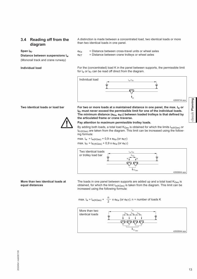
Individual load
Individual load
42608744.eps
Two identical loads or load bar
Two identical loads or trolley load bar
K
Iw IKr/
For two or more loads at a maintained distance in one panel, the max. Iw or IKr must never exceed the permissible limit for one of the individual loads. The minimum distance (eKa, eKT) between loaded trolleys is that defi ned by the articulated frame or crane traverse.Pay attention to maximum permissible trolley loads.By adding both loads, a total load KGes is obtained for which the limits lw(KGes) or IKr(KGes) are taken from the diagram. This limit can be increased using the follow-ing formula:max. lw = lw(KGes) + 0,9 x eKa (or eKT)max. lKr = lKr(KGes) + 0,9 x eKa (or eKT)
42608844.eps
Iw IKr/e Ka
K
KGes
K
More than two identical loads at equal distances
The loads in one panel between supports are added up and a total load KGes is obtained, for which the limit Iw(KGes) is taken from the diagram. This limit can be increased using the following formula:
More than two identical loads
42608944.eps
IweKa eKa eKa
K Ges
max. lw = lw(KGes) +n
x eKa (or eKT); n = number of loads K2
A distinction is made between a concentrated load, two identical loads or more than two identical loads in one panel.
eKa = Distance between cross-travel units or wheel axleseKT = Distance between crane trolleys or wheel axles
For the (concentrated) load K in the panel between supports, the permissible limit for lw or lKr can be read off direct from the diagram.

14 2032
45k1
.indd
/261
109
Plan
ning
Suspension load
I w I wGAB
eKT
K Ges
The suspension fi tting with the worst-case load is considered in the following.
Max. permissible load GAB on one suspension fi ttingAluline 120: max. GAB = 750 kgAluline 180: max. GAB = 1400 kg
The load on one suspension fi tting is calculated from K for monorail or suspension crane tracks and from the proportional track girder dead weight.
Proportional track girder dead weight = max. distance between fi ttings x track girder weight/m x 1,25.
GB = Track girder weight/m; lw = max. distance between suspension fi ttingsGAB = KGes + GB x lw x 1,25
3.5 Calculating load GAB on one suspension fi tting
Individual load
The load on one fi tting is determined from the sum total of all concentrated loads in two panels and from the proportional track dead weight. If the load on one suspen-sion fi tting determined according to this formula exceeds the admissible limit, one or both of the following measures is required:
• Reduce the spacing between supports by providing additional suspension fi t-tings
• Distribute loads so to arrange them at a safe distanceGAB = KGes + GB x lw x 1,25
Individual load
Two or more loads in one of two panels between supports
Two loads or groups of loads at a distance eKT
eKT = 0.5 x lw : GAB = 0.9KGes + GB x lw x 1,25eKT = lw : GAB = 0,7KGes + GB x lw x 1,25 (load distance = suspension dis-tance)eKT = 1,5 x lw : GAB = 0,5KGes + GB x lw x 1,25
Several identical loads
Identical load groups
42609144.eps
42609044.eps
42609244.eps
G ABI W I W
K Ges
I W I WGAB
K Ges

152032
45k1
.indd
/261
109
Plan
ning
The stability of the track section should be checked for short tracks and crane girders. (Multiply load on overhang by a factor of 1,2; crane girder forms counter torque).Aluline tracks or cranes must not be lifted (e.g. where the load is on the overhang)If the girder is unstable (girder is lifted, suspension fi tting is relieved of load), the suspension fi tting is subjected to impact loading which causes wear and can lead to premature failure of the connection.Solution: Use Aluline ergo suspensions and/or ergo crane end carriages.
The maximum and minimum lengths of overhang for cranes can be found in the crane selection table. They are directly related to the crane girder length.The length of overhang u can be increased for• fl at cable supply lines by the length of the accumulated cable trolleys at the end
of the track where accumulation takes place,• unloaded spacer trolleys – by the corresponding overall dimension.
The overhang at either end applicable to double-girder cranes running on more than two tracks is that shown in the selection table for cranes with the same SWL and comparable span.
Refer to the crane selection tables for the maximum lengths of overhang u for single-girder cranes.
Approach dimension lan (load hook centre to girder end) is derived from the dimen-sions of the individual components.
A suspension fi tting has to be provided in the vicinity of each track joint.
Crane overhang
Approach dimension
Permissible distance st of joint from suspension fi tting
Drive
Defl ection
3.6 System dimensions and system limits
Overhang Aluline 120 Aluline 180Shortest possible overhang u min [mm] 40 50Project engineering values for overhang u [mm] 200 300
Track overhang
KBK Aluline single and double-girder cranes, and monorail and double-rail trolleys, can be easily moved by hand. Crabs and rigid cranes can also be fi tted with elec-tric or pneumatic drives.
If the maximum spacing between supports/crane span is selected from the mid-dle load range in the selection diagram, the defl ection ratio ranges from 1/350 to 1/500. Defl ection can be reduced by using larger Aluline or steel profi le sections.
Aluline 120 Aluline 180
Minimum distance st min [mm]lw ≤ 5 m 40 50lw > 5 m 0,05 . lw
Maximum permissible distance st max [mm] 0,1 . lw

16 2032
45k1
.indd
/261
109
Plan
ning
3.7 Hoists with KBK
Use of balancer with KBK
The layout diagrams and tables in KBK documentation are valid for Demag chain hoists with lifting speeds up to max. 16 m/min.
The use of other chain hoists may result in an overload of the crane installation at limit speeds. Higher hoist speeds and weights may be considered by means of the following factor using the diagrams:
GHnew = GH x (0,97 + 0,002 x vH)
vH = Hoist speed in m/min
Balancers on KBK:The following must be considered when rope balancers are used on KBK:- Rope balancers operate at higher speeds and have higher acceleration values
than chain hoists. This increases the lifted load coeffi cient. The air cushion re-duces the negative effect of the high acceleration.
- In load handling applications, smaller defl ections and vibrations are often re-quired than those in classic crane applications.
Pneumatic rope balancers with lifting speeds up to max. 60 m/min may be used if- a factor of at least 1,1 is used to calculate load K by means of the diagrams ⇒
K = GH x 1,1 + G3 (this factor may be increased to avoid high defl ections and unwanted vibrations)- the selection table for 80 kg is used for the D-BP 55 and the selection table for
160 kg is used for the D-BP 110 (at rated SWL) in a simplifi ed manner.
Higher hoist speeds

172032
45k1
.indd
/261
109
Plan
ning

18 2032
45k1
.indd
/261
109
Plan
ning
42603946.eps
Design: Flexible track suspensions
Suspension monorailComponents Components See chapter/sectionRail elements Rail, joint bolt set, end cap, buffer, internal buffer stop, information plates 5
Track suspension Suspension, short suspension, upper suspension bracket, upper suspension clamp, ball-head suspension rod, suspension rod, ball-head bolt, track suspension clamp, spring clip 6
Trolley combination Trolley, load bar, traverse 7Travel drive RF 100, RF 125 and DRF 200 11Link bars Trolley link, link bar, spacer bar 13Accessories Buffers on crabs, trolley fi ttings 14Elec. power supply Cable slider, cable trolley, trailing cable, conductor line 16.1Pneum. power supply Cable trolley, protective hose, compressed air lines, fi ttings 16.2Control 17
3.8 Suspension monorails3.8.1 Specifying suspension
monorails

192032
45k1
.indd
/261
109
Plan
ning
Tracks according to DIN 4132: H1; B3GH = Hoist loadK(1) = Total load (live load + trolley dead weight)K(2) = Total load with electric/pneumatic driveeKa = Distance between trolley axles (axle base)lw = Spacing between supports for one trolleyGAB = Suspension load for one trolley
Selection basis: 1 load on the monorail trackThe KBK Aluline monorail selection table is based on the diagram in section 3.2. In individual cases, exact static analysis calculations may lead to different results. Enquire about details for higher or multiple loads on one track.
Aluline 120 Aluline 180
GHK(1) eKa lw GAB
K(1) eKa lw GABK(2) K(2)
[kg] [kg] [m] [m] [kg] [kg] [m] [m] [kg]
5075 0,106 6,00 120 75 0,150 8,00 18090 0,106 5,45 130 105 0,150 8,00 210
80105 0,106 5,05 145 105 0,150 8,00 210120 0,106 4,75 155 135 0,150 8,00 240
125160 0,106 4,10 195 170 0,150 8,00 280175 0,106 3,90 205 200 0,150 7,60 310
160205 0,106 3,60 235 205 0,150 7,55 310220 0,106 3,50 250 235 0,150 7,05 335
200245 0,106 3,30 270 245 0,150 6,90 340260 0,106 3,20 285 275 0,150 6,50 365
250300 0,106 3,00 320 305 0,150 6,15 390315 0,106 2,90 335 335 0,150 5,90 415
315370 0,210 2,80 390 370 0,150 5,60 450385 0,210 2,75 405 400 0,150 5,40 475
400455 0,210 2,45 470 455 0,150 5,05 520470 0,210 2,35 485 485 0,150 4,90 545
500590 0,210 1,90 605 590 0,150 4,40 655605 0,210 1,85 620 620 0,150 4,30 685
630720 0,250 4,10 780750 0,250 4,00 810
800890 0,250 3,50 940920 0,250 3,40 970
10001090 0,250 2,90 11301120 0,250 2,80 1160
3.8.2 Specifying monorails according to selection table

20 2032
45k1
.indd
/261
109
Plan
ning
42604048.eps
Design: a) Articulated track and crane suspensions (shown) b) Articulated track suspensions with rigid crane end carriages
Crane girder without a rail joint
Single-girder craneComponents Components See chapter/sectionRail elements Rail, joint bolt set, end cap, buffer, internal buffer stop, information plates 5
Track suspension Suspension, short suspension, upper suspension bracket, upper suspension clamp, ball-head suspension rod, suspension rod, ball-head bolt, track suspension clamp, spring clip 6
Trolley combination Trolley, load bar, traverse, trolley assembly, crane suspension eye, rigid crane end carriage 7
Travel drive RF 100, RF 125 and DRF 200 11Link bars Trolley link, link bar, spacer bar 13Accessories Buffers on crabs and cranes 14Elec. power supply Cable slider, cable trolley, trailing cable, conductor line 16.1Pneum. power supply Cable trolley, protective hose, compressed air lines, fi ttings 16.2Control 17
3.9 Single and double-girder cranes
3.9.1 Specifying single-girder cranes

212032
45k1
.indd
/261
109
Plan
ning
3.9.2 Specifying double-girder cranes
42604047.eps
Design: Articulated track suspensions with rigid crane end carriages (Articulated crane girder suspensions will not be provided).
Frame for double-girder crane
Rigid crane traverse
Double-girder craneComponents Components See chapter/sectionRail elements Rail, joint bolt set, end cap, buffer, internal buffer stop, information plates 5
Track suspension Short suspension, upper suspension bracket, upper suspension clamp, ball-head suspen-sion rod, suspension rod, track suspension clamp, spring clip 6
Trolley combination Trolley, load bar, frame for double-girder crane, rigid end carriage, crab frame 7Travel drive RF 100, RF 125 and DRF 200 11Link bars Trolley link, link bar, spacer bar 13Accessories Buffers on crabs and cranes 14Elec. power supply Cable slider, cable trolley, trailing cable, conductor line 16.1Control 17
22 2032
45k1
.indd
/261
109
Plan
ning
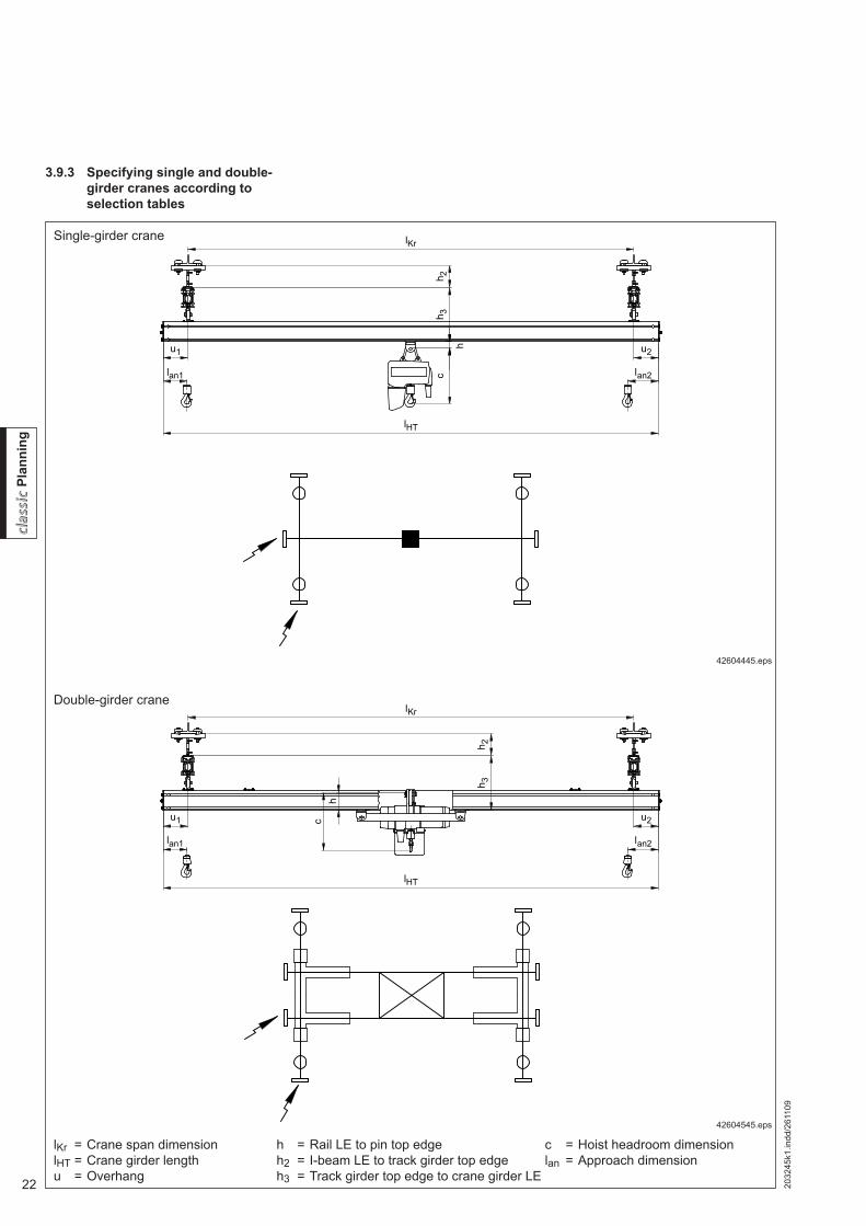
3.9.3 Specifying single and double-girder cranes according to selection tables
lKr = Crane span dimensionlHT = Crane girder lengthu = Overhang
42604445.eps
42604545.eps
h = Rail LE to pin top edgeh2 = I-beam LE to track girder top edgeh3 = Track girder top edge to crane girder LE
c = Hoist headroom dimensionlan = Approach dimension
Single-girder crane
Double-girder crane

232032
45k1
.indd
/261
109
Plan
ning
lW data apply to one crane on the crane runwayCrane girder overhangs are always the same on both sides of the crane.Defl ection limits:Cranes and runways 1/350, frequency ≥ 2,8 HzlHT = Crane girder lengthlKr = Crane span dimensionlw = Distance between suspensions
Suspension loads on requestAll dimensions in mMax. hoist speed 16 m/min
1) Two end carriages on each side of the crane2) Double trolley unit
Load capacity: 50 kgHoist weight: 35 kg
Load capacity: 80 kgHoist weight: 35 kg
Single-girder crane Double-girder crane Single-girder crane Double-girder cranelKr lw lKr lw lKr lw lKr lw
Aluline 120
Aluline 180
Aluline 120
Aluline 180
Aluline 120
Aluline 180
Aluline 120
Aluline 180lHT min max min max min max min max
Cra
ne g
irder
sec
tion,
cra
ne g
irder
leng
th
Alu
line
120
1 0,80 - 0,90 5,20 8,00 0,25 - 0,90 4,80 8,00 0,80 - 0,90 4,60 8,00 0,25 - 0,90 4,35 8,002 1,65 - 1,90 5,05 8,00 1,05 - 1,90 4,40 8,00 1,70 - 1,90 4,45 8,00 1,10 - 1,90 4,05 8,003 2,45 - 2,90 4,90 8,00 1,80 - 2,90 4,25 8,00 2,55 - 2,90 4,35 8,00 1,85 - 2,90 3,90 7,954 3,20 - 3,90 4,80 8,00 2,40 - 3,90 4,15 8,00 3,35 - 3,90 4,30 8,00 2,55 - 3,90 3,80 7,755 3,85 - 4,90 4,70 8,00 2,95 - 4,90 4,00 8,00 4,05 - 4,80 4,20 8,00 3,20 - 4,90 3,70 7,556 4,95 - 5,55 4,70 8,00 3,45 - 5,90 3,80 7,65 - - - 3,75 - 5,90 3,55 7,157 - - - 4,50 - 6,90 3,80 7,65 - - - 4,80 - 6,35 3,55 7,158 - - - 5,70 - 7,25 3,85 7,70 - - - 6,00 - 6,35 3,60 7,15
Alu
line
180
1 0,70 - 0,90 5,05 8,00 0,20 - 0,90 4,85 8,00 0,75 - 0,90 4,50 8,00 0,20 - 0,90 4,40 8,002 1,50 - 1,90 4,80 8,00 0,80 - 1,90 4,05 8,00 1,55 - 1,90 4,30 8,00 0,80 - 1,90 3,75 7,653 2,15 - 2,90 4,60 8,00 1,40 - 2,90 3,85 7,80 2,30 - 2,90 4,15 8,00 1,50 - 2,90 3,60 7,304 2,75 - 3,90 4,45 8,00 1,90 - 3,90 3,65 7,45 2,95 - 3,90 4,05 8,00 2,05 - 3,90 3,45 7,005 3,25 - 4,90 4,30 8,00 2,30 - 4,90 3,50 7,15 3,55 - 4,90 3,95 8,00 2,55 - 4,90 3,30 6,706 3,70 - 5,90 4,15 8,00 2,65 - 5,90 3,30 6,65 4,05 - 5,90 3,85 7,85 2,95 - 5,90 3,15 6,307 4,10 - 6,90 4,05 8,00 3,00 - 6,90 3,20 6,45 4,55 - 6,90 3,75 7,70 3,35 - 6,90 3,05 6,158 5,00 - 7,90 4,05 8,00 3,40 - 7,90 3,15 6,30 5,70 - 7,90 3,75 7,75 3,65 - 7,90 3,00 5,95
Load capacity: 125 kgHoist weight: 35 kg
Load capacity: 160 kgHoist weight: 35 kg
Single-girder crane Double-girder crane Single-girder crane Double-girder cranelKr lw lKr lw lKr lw lKr lw
Aluline 120
Aluline 180
Aluline 120
Aluline 180
Aluline 120
Aluline 180
Aluline 120
Aluline 180lHT min max min max min max min max
Cra
ne g
irder
sec
tion,
cra
ne g
irder
leng
th
Alu
line
120
1 0,80 - 0,90 3,95 8,00 0,25 - 0,90 3,85 7,90 0,80 - 0,90 3,65 7,45 0,25 - 0,90 3,60 7,302 1,75 - 1,90 3,90 7,95 1,15 - 1,90 3,60 7,35 1,75 - 1,90 3,55 7,30 1,15 - 1,90 3,35 6,853 2,65 - 2,90 3,80 7,85 1,95 - 2,90 3,55 7,15 2,65 - 2,90 3,50 7,20 2,00 - 2,90 3,30 6,654 3,45 - 3,90 3,75 7,75 2,70 - 3,90 3,45 7,00 3,55 - 3,65 3,45 7,10 2,80 - 3,90 3,25 6,555 - - - 3,40 - 4,90 3,40 6,85 - - - 3,50 - 4,90 3,15 6,406 - - - 4,05 - 5,50 3,25 6,55 - - - 4,20 - 5,05 3,10 6,157 - - - 5,10 - 5,50 3,25 6,55 - - - - - -8 - - - - - - - - - - - -
Alu
line
180
1 0,75 - 0,90 3,90 8,00 0,20 - 0,90 3,95 8,00 0,75 - 0,90 3,60 7,35 0,20 - 0,90 3,70 7,502 1,60 - 1,90 3,75 7,75 0,85 - 1,90 3,40 6,95 1,65 - 1,90 3,50 7,15 0,85 - 1,90 3,20 6,503 2,40 - 2,90 3,70 7,55 1,60 - 2,90 3,30 6,65 2,45 - 2,90 3,40 7,00 1,65 - 2,90 3,10 6,254 3,15 - 3,90 3,60 7,40 2,20 - 3,90 3,15 6,40 3,25 - 3,90 3,35 6,85 2,30 - 3,90 3,00 6,055 3,80 - 4,90 3,50 7,20 2,80 - 4,90 3,10 6,20 3,95 - 4,90 3,25 6,70 2,90 - 4,90 2,90 5,906 4,45 - 5,90 3,45 7,05 3,30 - 5,90 2,95 5,90 4,60 - 5,90 3,20 6,60 3,45 - 5,90 2,80 5,607 5,05 - 6,90 3,40 6,95 3,70 - 6,90 2,90 5,75 5,35 - 6,90 3,15 6,50 3,95 - 6,90 2,75 5,508 6,30 - 7,90 3,40 7,00 4,10 - 7,90 2,80 5,60 6,55 - 7,65 3,20 6,55 4,40 - 7,90 2,70 5,35

24 2032
45k1
.indd
/261
109
Plan
ning
Project engineering data for crane installations should be selected from the follow-ing tables. In individual cases, exact static analysis calculations may lead to differ-ent results for lKr and lw.Where there are several cranes on the same runway, the end carriages of single-girder cranes must always be designed as double trolleys.Distances between suspensions lw must be calculated separately. Data calculated on the basis of cranes of standard design for standard components and without special attachments. Check suspension loads.
Cranes according to DIN 15018, tracks according to DIN 4132: H1, B3
1) Two end carriages on each side of the crane2) Double trolley unit
Load capacity: 200 kgHoist weight: 35 kg
Load capacity: 250 kgHoist weight: 35 kg
Single-girder crane Double-girder crane Single-girder crane Double-girder cranelKr lw lKr lw lKr lw lKr lw
Aluline 120
Aluline 180
Aluline 120
Aluline 180
Aluline 120
Aluline 180
Aluline 120
Aluline 180lHT min max min max min max min max
Cra
ne g
irder
sec
tion,
cra
ne g
irder
leng
th
Alu
line
120
1 0,85 - 0,90 3,35 6,85 0,25 - 0,90 3,35 6,80 0,85 - 0,90 3,05 6,25 0,25 - 0,90 3,10 6,252 1,80 - 1,90 3,25 6,70 1,15 - 1,90 3,15 6,35 1,80 - 1,90 3,00 1) 6,15 1,20 - 1,90 2,90 5,903 2,70 - 2,90 3,25 6,65 2,05 - 2,90 3,10 6,20 2,70 - 2,90 2,95 1) 6,10 2,05 - 2,90 2,85 5,754 - - - 2,85 - 3,90 3,05 6,10 - - - 2,90 - 3,90 2,85 5,705 - - - 3,60 - 4,65 3,00 6,00 - - - 3,70 - 4,25 2,80 5,606 - - - 4,35 - 4,65 2,90 5,80 - - - - - -7 - - - - - - - - - - - -8 - - - - - - - - - - - -
Alu
line
180
1 0,75 - 0,90 3,30 6,80 0,20 - 0,90 3,45 7,00 0,75 - 0,90 3,00 6,20 0,20 - 0,90 3,20 6,502 1,65 - 1,90 3,20 6,60 0,90 - 1,90 3,00 6,10 1,70 - 1,90 2,95 1) 6,05 0,90 - 1,90 2,80 5,653 2,50 - 2,90 3,15 6,45 1,70 - 2,90 2,90 5,90 2,55 - 2,90 2,90 1) 5,95 1,75 - 2,90 2,75 5,504 3,30 - 3,90 3,10 6,35 2,40 - 3,90 2,85 5,70 3,40 - 3,90 2,85 1) 5,85 2,50 - 3,90 2,65 5,355 4,05 - 4,90 3,05 6,25 3,05 - 4,90 2,75 5,55 4,20 - 4,90 2,80 1) 5,80 3,15 - 4,90 2,60 5,256 4,80 - 5,90 3,00 1) 6,15 3,65 - 5,90 2,70 5,35 4,95 - 5,90 2,80 1) 5,70 3,80 - 5,90 2,55 5,057 5,60 - 6,90 2,95 1) 6,10 4,15 - 6,90 2,65 5,25 5,75 - 6,35 2,75 1) 5,65 4,40 - 6,90 2,50 4,958 6,75 - 6,95 2,95 1) 6,10 4,65 - 7,90 2,60 5,10 - - - 4,95 - 7,90 2,45 4,85
Load capacity: 315 kgHoist weight: 55 kg
Load capacity: 400 kgHoist weight: 55 kg
Single-girder crane Double-girder crane Single-girder crane Double-girder cranelKr lw lKr lw lKr lw lKr lw
Aluline 120
Aluline 180
Aluline 120
Aluline 180
Aluline 120
Aluline 180
Aluline 120
Aluline 180lHT min max min max min max min max
Cra
ne g
irder
sec
tion,
cra
ne g
irder
leng
th
Alu
line
120
1 0,65 - 0,90 2) 2,70 1) 5,55 0,25 - 0,90 2,80 5,60 0,65 - 0,90 2) 2,45 1) 5,00 0,25 - 0,90 2,55 5,102 1,60 - 1,90 2) 2,65 1) 5,45 1,20 - 1,90 2,65 5,25 1,60 - 1,90 2) 2,40 1) 4,95 1,20 - 1,90 2,40 4,803 2,55 - 2,65 2) 2,65 1) 5,40 2,10 - 2,90 2,60 5,20 - - - 2,15 - 2,90 2,40 4,754 - - - 2,95 - 3,75 2,55 5,10 - - - 3,00 - 3,40 2,35 4,705 - - - - - - - - - - - -6 - - - - - - - - - - - -7 - - - - - - - - - - - -8 - - - - - - - - - - - -
Alu
line
180
1 0,75 - 0,90 2,70 1) 5,50 0,20 - 0,90 2,90 5,85 0,75 - 0,90 2,45 1) 5,00 0,20 - 0,90 2,65 5,352 1,70 - 1,90 2,65 1) 5,40 0,90 - 1,90 2,55 5,10 1,70 - 1,90 2,40 1) 4,90 0,95 - 1,90 2,35 4,703 2,60 - 2,90 2,60 1) 5,30 1,80 - 2,90 2,50 5,00 2,65 - 2,90 2,35 1) 4,85 1,80 - 2,90 2,30 4,604 3,45 - 3,90 2,55 1) 5,25 2,55 - 3,90 2,45 4,90 3,55 - 3,90 2,35 1) 4,80 2,65 - 3,90 2,30 4,505 4,30 - 4,90 2,55 1) 5,20 3,30 - 4,90 2,40 4,80 4,40 - 4,90 2,30 1) 4,75 3,40 - 4,90 2,25 4,456 5,10 - 5,55 2,50 1) 5,10 4,00 - 5,90 2,35 4,65 - - - 4,15 - 5,90 - 4,357 - - - 4,65 - 6,90 2,30 4,55 - - - 4,85 - 6,90 - 4,258 - - - 5,25 - 7,65 2,30 4,50 - - - 5,50 - 6,95 - 4,20

252032
45k1
.indd
/261
109
Plan
ning
1) Two end carriages on each side of the crane2) Double trolley unit
Load capacity: 500 kgHoist weight: 55 kg
Load capacity: 630 kgHoist weight: 55 kg
Single-girder crane Double-girder crane Single-girder crane Double-girder cranelKr lw lKr lw lKr lw lKr lw
Aluline 120
Aluline 180
Aluline 120
Aluline 180
Aluline 120
Aluline 180
Aluline 120
Aluline 180lHT min max min max min max min max
Cra
ne g
irder
sec
tion,
cra
ne g
irder
leng
th
Alu
line
120
1 0,65 - 0,90 2) 2,20 1) 4,55 0,25 - 0,90 2,35 4,70 - - - - - -2 1,60 - 1,90 2) 2,15 1) 4,50 1,20 - 1,90 2,25 4,40 - - - - - -3 - - - 2,15 - 2,90 - 4,35 - - - - - -4 - - - 3,05 - 3,10 - 4,30 - - - - - -5 - - - - - - - - - - - -6 - - - - - - - - - - - -7 - - - - - - - - - - - -8 - - - - - - - - - - - -
Alu
line
180
1 0,75 - 0,90 2,15 1) 4,55 0,20 - 0,90 2,45 4,90 0,50 - 0,90 2) - 4,10 1) 0,20 - 0,90 2,25 4,452 1,75 - 1,90 2,10 1) 4,45 0,95 - 1,90 - 4,35 1,50 - 1,90 2) - 4,00 1) 0,95 - 1,90 - 3,953 2,65 - 2,90 2,05 1) 4,40 1,85 - 2,90 - 4,25 2,45 - 2,90 2) - 4,00 1) 1,85 - 2,90 - 3,904 3,55 - 3,90 - 4,35 1) 2,70 - 3,90 - 4,15 3,35 - 3,90 2) - 3,95 1) 2,75 - 3,90 - 3,855 4,45 - 4,55 - 4,30 1) 3,50 - 4,90 - 4,10 - - - 3,60 - 4,90 - 3,806 - - - 4,30 - 5,90 - 4,05 - - - 4,40 - 5,75 - 3,707 - - - 5,00 - 6,35 - 4,00 - - - 5,15 - 5,75 - 3,708 - - - 5,70 - 6,35 - 3,95 - - - - - -
Load capacity: 800 kgHoist weight: 55 kg
Load capacity: 1,000 kgHoist weight: 55 kg
Single-girder crane Double-girder crane Single-girder crane Double-girder cranelKr lw lKr lw lKr lw lKr lw
Aluline 120
Aluline 180
Aluline 120
Aluline 180
Aluline 120
Aluline 180
Aluline 120
Aluline 180lHT min max min max min max min max
Cra
ne g
irder
sec
tion,
cra
ne g
irder
leng
th
Alu
line
120
1 - - - - - - - - - - - -2 - - - - - - - - - - - -3 - - - - - - - - - - - -4 - - - - - - - - - - - -5 - - - - - - - - - - - -6 - - - - - - - - - - - -7 - - - - - - - - - - - -8 - - - - - - - - - - - -
Alu
line
180
1 0,50 - 0,90 2) - 3,70 1) 0,20 - 0,90 2,05 4,05 0,50 - 0,90 2) - 3,15 1) 0,20 - 0,90 0,80 3,652 1,50 - 1,90 2) - 3,60 1) 0,95 - 1,90 - 3,60 1,50 - 1,90 2) - 3,05 1) 0,95 - 1,90 - 3,203 2,45 - 2,90 2) - 3,60 1) 1,90 - 2,90 - 3,55 2,45 - 2,90 2) - 3,00 1) 1,90 - 2,90 - 3,104 3,40 - 3,65 2) - 3,55 1) 2,80 - 3,90 - 3,50 - - - 2,85 - 3,90 - 3,055 - - - 3,65 - 4,90 - 3,45 - - - 3,70 - 4,65 - 3,006 - - - 4,50 - 5,20 - 3,40 - - - - - -7 - - - - - - - - - - - -8 - - - - - - - - - - - -

26 2032
45k1
.indd
/261
109
Plan
ning
3.10 Structural dimensions for monorail tracks and cranes
Suspension monorail Single-girder crane Double-girder crane
42603445.eps
The lifting height achieved by using a double-girder crane is higher than that of single-girder cranes, as the hoist is positioned between the two crane girders.
For lw, lKr, lHT, see diagram (section 3.2) and selection tables (section 3.9.3).u, st, lan according to design layout and individual dimensions of the components.
Rigid crane traverses: + 15
Dimension c = Hoist headroom dimension
Dimension h3 [mm] (track girder top edge to crane girder bottom edge)Suspension monorail Crane
Aluline Aluline crane runway 120 180120 180 Aluline crane girder 120 180 120 180
120 180 Trolleyssingle 330 390 390 450double 340 400 405 465
Dimension h [mm] (bottom edge of rail to top edge of pin)Crane and suspension monorail
Aluline 120 180
Hoist trolleyssingle 36,5 35double 46 50
Double-girder crab frame -105 -150
Dimension h2 [mm] (I-beam bottom edge to track girder top edge)
Short suspension with spring clip
Length of suspension rod for spring clip80 100 300
Aluline 120 75 135 - 355Aluline 180 115 - 195 395
Dimension h
Dimension h3
Dimension h2

272032
45k2
.indd
/261
109
Plan
ning
4 KBK Aluline ergo – Planning and project engineering
The following pages provide an overview of the applications for which the various Aluline profi le sections may be used for:• Cranes with a large overhang• Manipulator cranes and crabsRigid ergo trolleys integrated into special end carriages and trolley frames, togeth-er with rigid suspensions accommodate load torques and forces acting in the op-posite direction to the load. KBK ergo trolleys can accommodate horizontal forces resulting from handling devices.The crane runway length must not exceed 30 meters when rigid suspensions are used. (Different expansion coeffi cients for support structure and aluminium rail).
4.1 Cranes with a large overhang
4.1.1 Single-girder crane with a large overhang
42604245.eps
Design: Rigid track suspensions and crane end carriages
Single-girder crane with a large overhang
Single-girder craneComponents Components See chapter/sectionRail elements Rail, joint bolt set, end cap, buffer, internal buffer stop, shock absorber, information plates 5Track suspension Short suspension, Ergo suspension 6Trolley combination Trolley, ergo crane trolley, ergo crab trolley 7Travel drive RF 100, RF 125 and DRF 200 11Link bars Trolley link, link bar, spacer bar 13Accessories Buffers on crabs and cranes 14Elec. power supply Cable slider, cable trolley, trailing cable, conductor line 16.1Control 17

28 2032
45k2
.indd
/261
109
Plan
ning
42604345.eps
Double-girder crane with a large overhang
4.1.2 Double-girder crane with a large overhang
Double-girder craneComponents Components See chapter/sectionRail elements Rail, joint bolt set, end cap, buffer, internal buffer stop, shock absorber, information plates 5Track suspension Short suspension, Ergo suspension 6Trolley combination Trolley, ergo crane trolley, ergo crab trolley 7Travel drive RF 100, RF 125 and DRF 200 11Link bars Trolley link, link bar, spacer bar 13Accessories Buffers on crabs and cranes 14Elec. power supply Cable slider, cable trolley, trailing cable, conductor line 16.1Control 17

292032
45k2
.indd
/261
109
Plan
ning
c
I wIKa
u1
hh
c
h2 u 2I Kr
I Kr
I HT
h 3
I A1
IA1
h3
u 2
I HT
eKT
eK
a
I A1
I A1
u2
I Ka
u 1
e KT
u1
h2
42069944.eps
Single-girder crane
Double-girder craneAluline 180:275(150)
Aluline 120: 415Aluline 180: 540
Crane girders may have overhang u2 on both sides if crane length lHT is increased accordingly and crane span dimension lKR is maintained.Refer to the crane selection table in section 4.1.3 for values for maximum permis-sible overhang travel dimension lA1.Crane types:• Single-girder crane: Cranes and runways made of KBK Aluline 180• Double-girder crane: Cranes and runways made of KBK Aluline 180
A KBK Aluline double trolley with an articulated frame is used as the crab for sin-gle-girder cranes with a large overhang. (For cranes up to lHT = 3 meters, a single trolley is suffi cient for the crab.)A KBK Aluline crab frame is used as the crab for double-girder cranes. KBK Aluline end caps with rubber buffers are used at the ends of the runway and at the ends of the crane girders.
The hoist/load connection is articulated.
lKr = Crane span dimension u1 = OverhanglHT = Crane girder length u2 = OverhanglKa = Crab span h = Rail LE to pin top edgeeKT = Distance between crane trolleys h2 = I-beam LE to track girder top
edgeeKa = Distance between cross-travel units h3 = Track girder top edge to
crane girder LElA1 = Permissible overhang travel dimension c = Hoist headroom dimension

30 2032
45k2
.indd
/261
109
Plan
ning
Larger overhangs are possible using cranes built with KBK Aluline ergo compo-nents.The maximum overhang travel distance, the suspension distance and the suspen-sion load can be taken from the following tables depending on the load to be lifted and the crane girder length. The tables are based on the following specifi ed values and conditions:• u1 = 250 mm• Track overhang: 200 mm• u2 < lKr• Maximum possible overhang dimension lA1 according to profi le and crane type:
Overhang dimension IA1 depends on the load to be lifted.Layout of results in the tables:
Example The example is indicated in the table byGH = 250 kg; lHT = 5 m; crane type: Double-girder craneThe limits for the values sought are as follows:Aluline 180 Overhang travel dimension: max lA1 = 885 mm Suspension distance: lw = 2,0 – 3,4 m Suspension load: GAB = 20 / 625 kg
Aluline 180 runway and crane
GH lHTGhoist unit Type 2 m 3 m 4 m 5 m 6 m
50 kg Single-girder crane
760 1260 1500 1500 15002,0 - 5,0 -35 / 285 2,0 - 4,8 -35 / 295 2,0 - 4,8 -5 / 280 2,0 - 4,7 15 / 260 2,0 - 4,5 15 / 255
20 kg Double- girdercrane
625 1125 1625 2005 17752,0 - 4,5 -40 / 360 2,0 - 4,3 -40 / 390 2,0 - 4,2 -40 / 415 2,0 - 4,1 -25 / 425 2,0 - 4,0 20 / 380
80 kg Single-girder crane
760 1260 1500 1500 14502,0 - 4,5 -70 / 350 2,0 - 4,4 -70 / 365 2,0 - 4,5 -35 / 340 2,0 - 4,5 10 / 315 2,0 - 4,4 15 / 300
20 kg Double- girder crane
625 1125 1625 1655 14752,0 - 4,1 -75 / 430 2,0 - 4,0 -75 / 460 2,0 - 3,9 -75 / 485 2,0 - 4,0 0 / 440 2,0 - 3,9 20 / 405
125 kg Single-girder crane
760 1260 1470 1240 11302,0 - 3,9 -125 / 455 2,0 - 3,9 -125 / 470 2,0 - 4,0 -70 / 425 2,0 - 4,3 5 / 370 2,0 - 4,3 15 / 350
20 kg Double- girder crane
625 1125 1605 1335 12052,0 - 3,7 -130 / 535 2,0 - 3,6 -130 / 565 2,0 - 3,5 -125 / 585 2,0 - 3,9 15 / 480 2,0 - 4,3 20 / 455
160 kg Single-girder crane
760 1260 1250 1060 9702,0 - 3,6 -165 / 535 2,0 - 3,6 -165 / 550 2,0 - 3,9 -55 / 455 2,0 - 4,1 10 / 405 2,0 - 4,2 15 / 395
20 kg Double- girder crane
625 1125 1395 1175 10552,0 - 3,5 -170 / 615 2,0 - 3,4 170 / 645 2,0 - 3,4 -100 / 600 2,0 - 3,8 20 / 515 2,0 - 3,7 20 / 490
200 kg Single-girder crane
750 1250 1070 920 8402,6 - 3,3 -200 / 625 3,3 - 3,3 -200 / 640 2,0 - 3,8 -50 / 495 2,0 - 3,9 10 / 455 2,0 - 4,0 15 / 440
20 kg Double- girder crane
615 1105 1225 1035 9353,0 - 3,2 -200 / 700 2,9 - 3,2 -200 / 730 2,0 - 3,3 -85 / 635 2,0 - 3,6 20 / 560 2,0 - 3,6 20 / 540
250 kg Single-girder crane
660 1100 890 770
-
2,0 - 3,0 -200 / 690 2,5 - 3,1 -200 / 705 2,0 - 3,5 -45 / 560 2,0 - 3,7 10 / 525
30 kg Double- girder crane
545 985 1045 8852,1 - 3,3 -200 / 765 2,1 - 2,9 -200 / 795 2,0 - 3,2 -75 / 695 2,0 - 3,4 20 / 625
315 kg Single-girder crane
590 980 760 6602,5 - 2,8 -200 / 770 2,4 - 3,0 -200 / 785 2,0 - 3,3 -40 / 635 2,0 - 3,4 10 / 600
30 kg Double- girder crane
485 895 905 7752,0 - 2,8 -200 / 835 2,7 - 2,7 -200 / 875 2,0 - 3,1 -70 / 765 2,0 - 3,3 20 / 705
400 kg Single-girder crane
510 820 640
-
2,0 - 2,6 -200 / 865 2,0 - 2,9 -185 / 865 2,0 - 3,1 -40 / 735
30 kg Double- girder crane
425 785 7852,0 - 2,6 -195 / 935 2,0 - 2,6 -200 / 970 2,0 - 3,0 -65 / 865
500 kg Single-girder crane
440 700 5502,0 - 2,5 -200 / 980 2,0 - 2,7 -180 / 980 2,0 - 2,9 -45 / 855
30 kg Double- girder crane
375 695 6852,0 - 2,5 -200 / 1055 2,3 - 2,5 -200 / 1090 2,0 - 2,8 -70 / 985
Aluline 180Single-girder crane lA1 = 1,5 mDouble-girder crane lA1 = 2,3 m
lHT
SWL Single-girder cranelA1
min lw - max lw min GAB / max GAB
Hoist unitDouble-girder crane
lA1
min lw - max lw min GAB / max GAB
4.1.3 Specifying cranes with large overhang according to selection tables

312032
45k2
.indd
/261
109
Plan
ning
4.2 Structural dimensions for cranes with large overhang, manipulator cranes
The following tables list the structural dimensions of the various crane type assem-blies.The dimensions are shown on the crane type drawings.
The suspension headroom dimensions apply to the short adjustable KBK Aluline suspensions and KBK Aluline ergo suspensions.
Cranes
Double-rail track
Dimension h [mm] (bottom edge of rail to top edge of pin)Cranes and double rail track
Aluline 120 180
Hoist trolleys single 36,5 35 double 46 50 Crab frame -105 -150
Dimension h2 [mm] (I-beam bottom edge to crane girder top edge)Aluline 120 75Aluline 180 115
Dimension h3 [mm] (Track girder top edge / crane girder LE)Aluline crane runway 120 180
Aluline crane girder 120 180 120 180h3 300 360 410 470
Dimension h3 [mm] (crane runway height)Aluline crane runway 120 180
h3 120 180

32 2032
45k2
.indd
/261
109
Plan
ning
l w
lKr
lHT
e Ka
e KT l Ka
e KT
a 4
42610844.eps
42068744.eps42066644.eps
Design: Rigid runway and crane suspensions
4.3 Manipulator cranes4.3.1 Specifying manipulator crabs,
manipulator cranes
Double-girder craneComponents Components See chapter/sectionRail elements Rail, joint bolt set, end cap, buffer, internal buffer stop, shock absorber, information plates 5Track suspension Short suspension, Ergo suspension 6Trolley combination Trolley, ergo crane trolley, ergo crab trolley 7Travel drive RF 100, RF 125 and DRF 200 11Link bars Trolley link, link bar, spacer bar 13Accessories Buffers on crabs and cranes 14Elec. power supply Cable slider, cable trolley, trailing cable, conductor line 16.1
Control 17

332032
45k2
.indd
/261
109
Plan
ning
4.3.2 Specifying manipulator crabs according to selection table
Offset loads and the associated moments on manipulators and handling equip-ment result in special loads on crane installations.If forces acting in the opposite direction to gravity are exerted on the trolleys and suspensions, KBK Aluline ergo components must be used at the points concerned.Otherwise, KBK Aluline classic components can be used.Manipulators and handling equipment are bolted to a KBK ergo crab frame. The manipulator crab runs in a double-rail system or on a double-girder crane.End caps with shock absorbers are used as end caps. For total weights of less than 300 kg and vertical loads, end caps with cellular foam rubber or rubber buff-ers can be used.
The dead weights of the crane and crab are included in the total weight.
Determining the device geometry, weights and moments is particularly important for specifying the crab frame size and the double-rail track.The table in section 3 provides the basis for dimensioning a double-rail track.More precise calculations may result in different values.

34 2032
45k2
.indd
/261
109
Plan
ning
1. Determining the weights and moments from the device geometry Selection with example
42608444.eps
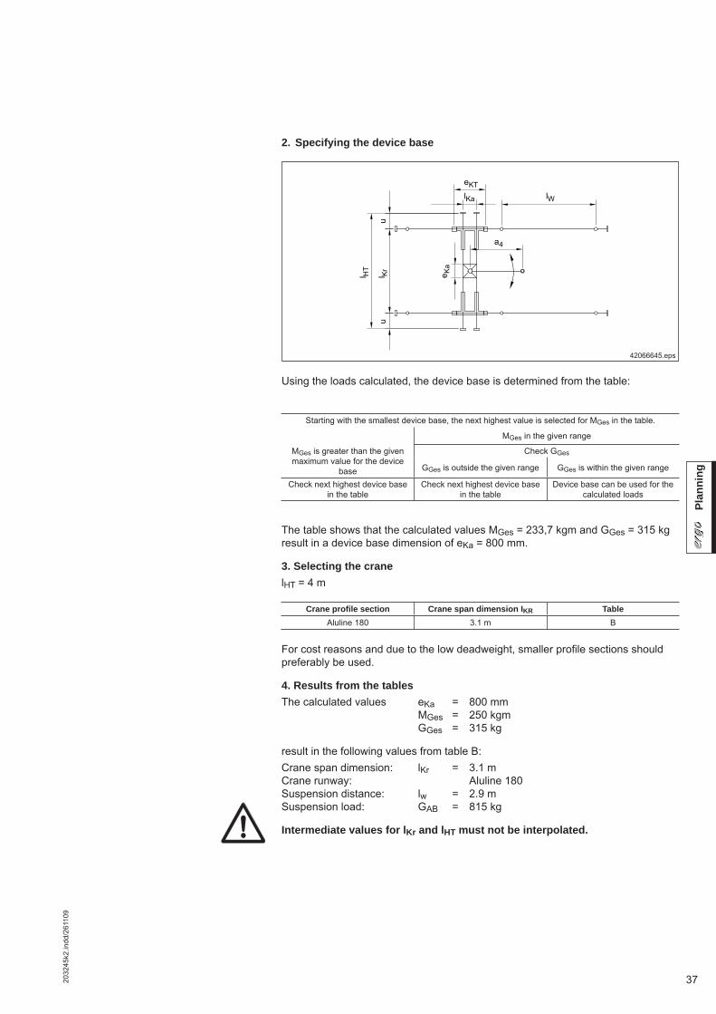
Using the loads calculated, the device base is determined from the table:
42068745.eps
The table shows that the calculated values MGes = 233,7 kgm and GGes = 265 kg result in a device base dimension of eKa = 1000 mm.
G1
G2
a3
a4
G4 GH+
h
H
I Ka
G3
LoadsCrab frame: G1 = 75 kgMast: G2 = 28 kgArm: G3 = 122 kgDevice: G4 = 10 kgLoad: GH = 30 kgTotal: GGes = 265 kg
Manual force: H = 5 kg
Distances:Arm: a3 = 0.94 mDevice: a4 = 2.60 mManual force: h = 3.00 m
Moments:Arm: G3 x a3 = 114.7 kgmDevice, load: (G4+GH) x a4 = 104.0 kgmManual force: H x h = 15.0 kgmTotal: MGes = 233,7 kgm
Starting with the smallest device base, the next highest value is selected for MGes in the table.MGes in the given range
MGes is greater than the given maximum value for the device
base
Check GGes
GGes is outside the given range GGes is within the given range
Check next highest device base in the table
Check next highest device base in the table
Device base can be used for the calculated loads
2. Specifying the device base
352032
45k2
.indd
/261
109
Plan
ning
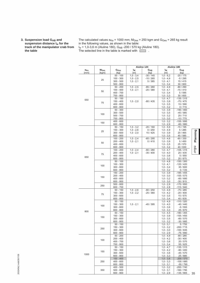
The calculated values eKa = 1000 mm; MGes = 250 kgm and GGes = 265 kg result in the following values, as shown in the table: lw = 1,0-3,6 m (Aluline 180), GAB -200 / 570 kg (Aluline 180). The selected line in the table is marked with .
3. Suspension load GAB and suspension distance lw for the track of the manipulator crab from the table
Aluline 120 Aluline 180eKa MGes GGes lW GAB lW GAB
[mm] [kgm] [kg] [m] [kg] [m] [kg]
550
25
50 - 100 1,0 - 3,4 -30 / 145 1,0 - 6,2 -20 / 175100 - 300 1,0 - 2,5 -10 / 265 1,0 - 4,9 -5 / 295300 - 500 1,0 - 2,1 5 / 385 1,0 - 4,1 15 / 415500 - 800 1,0 - 3,4 30 / 600
50
50 - 200 1,0 - 2,5 -85 / 260 1,0 - 4,9 -80 / 290100 - 400 1,0 - 2,1 -20 / 380 1,0 - 4,1 -15 / 410400 - 700 1,0 - 3,4 5 / 595700 - 800 1,0 - 3,3 30 / 655
75
50 - 150 1,0 - 4,7 -135 / 315150 - 400 1,0 - 2,0 -80 / 435 1,0 - 3,9 -75 / 470400 - 600 1,0 - 3,5 15 / 590600 - 800 1,0 - 3,2 0 / 715
100
50 - 300 1,0 - 3,9 -190 / 460300 - 500 1,0 - 3,5 -45 / 585500 - 700 1,0 - 3,2 25 / 710700 - 800 1,0 - 3,0 -10 / 770
150 400 - 600 1,0 - 3,2 -155 / 695600 - 800 1,0 - 2,9 -60 / 880
650
25
50 - 150 1,0 - 3,2 -20 / 160 1,0 - 5,9 -15 / 195150 - 300 1,0 - 2,6 0 / 250 1,0 - 4,9 5 / 285300 - 600 1,0 - 2,0 15 / 425 1,0 - 3,9 20 / 465600 - 800 1,0 - 3,5 45 / 585
50
100 - 200 1,0 - 2,4 -65 / 295 1,0 - 4,6 -60 / 330200 - 400 1,0 - 2,1 0 / 410 1,0 - 3,9 5 / 450400 - 600 1,0 - 3,5 25 / 570600 - 800 1,0 - 3,4 40 / 630
75
100 - 200 1,0 - 2,4 -80 / 280 1,0 - 4,7 -105 / 315200 - 400 1,0 - 2,1 -35 / 400 1,0 - 4,0 25 / 435400 - 600 1,0 - 3,6 5 / 555600 - 800 1,0 - 3,2 20 / 675
100
50 - 100 1,0 - 4,8 -150 / 300100 - 300 1,0 - 4,1 -120 / 420300 - 600 1,0 - 3,4 35 / 600600 - 800 1,0 - 3,2 0 / 725
150
150 - 200 1,0 - 3,9 -185 / 455200 - 400 1,0 - 3,0 -155 / 575400 - 600 1,0 - 3,2 -60 / 695600 - 800 1,0 - 3,0 -35 / 815
250 500 - 600 1,0 - 2,9 -170 / 850600 - 700 1,0 - 2,8 -115 / 940
800
75
50 - 150 1,0 - 2,6 -80 / 250 1,0 - 4,9 -75 / 285150 - 300 1,0 - 2,2 -25 / 360 1,0 - 4,2 -20 / 400300 - 600 1,0 - 3,5 15 / 575600 - 800 1,0 - 3,4 45 / 635
100
50 - 150 1,0 - 4,9 -110 / 320150 - 300 1,0 - 2,1 -45 / 395 1,0 - 4,0 -40 / 440300 - 600 1,0 - 3,6 -5 / 555600 - 800 1,0 - 3,3 25 / 670
150
50 - 150 1,0 - 4,5 -180 / 355150 - 300 1,0 - 3,9 -155 / 455300 - 600 1,0 - 3,5 -60 / 570600 - 800 1,0 - 3,2 -30 / 685
250
50 - 150 1,0 - 3,1 5 / 755150 - 300 1,0 - 3,2 -200 / 715300 - 600 1,0 - 3,0 -100 / 835600 - 800 1,0 - 2,9 -75 / 890
1000
100
50 - 200 1,0 - 4,9 -80 / 285200 - 400 1,0 - 4,2 -30 / 400400 - 700 1,0 - 3,6 20 / 570700 - 800 1,0 - 3,4 55 / 625
150
50 - 150 1,0 - 4,7 -135 / 315150 - 300 1,0 - 4,2 -90 / 400300 - 600 1,0 - 3,6 -45 / 570600 - 800 1,0 - 3,3 25 / 680
250150 - 400 1,0 - 3,6 -200 / 570400 - 600 1,0 - 3,3 -100 / 685600 - 800 1,0 - 3,1 -55 / 795
350400 - 500 1,0 - 3,2 -200 / 740500 - 600 1,0 - 3,1 -160 / 795600 - 800 1,0 - 2,9 -135 / 905

36 2032
45k2
.indd
/261
109
Plan
ning
4.3.3 Specifying manipulator cranes according to selection table
Determining the weights and moments from the device geometry is particularly important for specifying the crab frame size, the double-girder crane and the crane runway.Tables A and B in this section provide the basis for specifying the complete instal-lation.More precise calculations may result in different values.
1. Determining the weights and moments from the device geometry Selection with example
42608544.eps
LoadsCrab frame: G1 = 75 kgMast: G2 = 78 kgArm: G3 = 122 kgDevice: G4 = 10 kgLoad: GH = 30 kgTotal: GGes = 315 kg
Manual force: H = 5 kg
Distances:Arm: a3 = 0.94 mDevice: a4 = 2.60 mManual force: h = 3.00 m
Moments:Arm: G3 x a3 = 114.7 kgmDevice, load: (G4+GH) x a4 = 104.0 kgmManual force: H x h = 15.0 kgmTotal: MGes = 233,7 kgm
372032
45k2
.indd
/261
109
Plan
ning
Using the loads calculated, the device base is determined from the table:
42066645.eps
The table shows that the calculated values MGes = 233,7 kgm and GGes = 315 kg result in a device base dimension of eKa = 800 mm.
3. Selecting the cranelHT = 4 m
For cost reasons and due to the low deadweight, smaller profi le sections should preferably be used.
4. Results from the tablesThe calculated values eKa = 800 mm MGes = 250 kgm GGes = 315 kg
result in the following values from table B:Crane span dimension: lKr = 3.1 mCrane runway: Aluline 180Suspension distance: lw = 2.9 mSuspension load: GAB = 815 kg
Intermediate values for lKr and lHT must not be interpolated.
Starting with the smallest device base, the next highest value is selected for MGes in the table.
MGes in the given range
MGes is greater than the given maximum value for the device
base
Check GGes
GGes is outside the given range GGes is within the given range
Check next highest device base in the table
Check next highest device base in the table
Device base can be used for the calculated loads
Crane profi le section Crane span dimension IKR TableAluline 180 3.1 m B
2. Specifying the device base

38 2032
45k2
.indd
/261
109
Plan
ning
Manipulator cranes from the selection table
lHT = 2m lHT = 3mAluline 120 Aluline 180 Aluline 120 Aluline 180
eKa MGes GGes lKr lw GAB lw GAB lKr lw GAB lw GAB
[mm] [kgm] [kg] [m] [m] [kg] [m] [kg] [m] [m] [kg] [m] [kg]
550
25
50 - 100
1,50 - 1,85
1,0 - 3,0 -20 / 180 1,0 - 5,3 5 / 240 2,50 - 2,85 1,0 - 3,0 -20 / 180 1,0 - 5,3 5 / 240100 - 150 1,0 - 2,7 -15 / 235 1,0 - 4,8 20 / 290 2,50 - 2,85 1,0 - 2,6 -15 / 240 1,0 - 4,8 20 / 295150 - 200 1,0 - 2,4 -10 / 295 1,0 - 4,4 20 / 345 2,50 - 2,85 1,0 - 2,4 -5 / 300 1,0 - 4,4 25 / 350200 - 300 1,0 - 2,1 0 / 405 1,0 - 3,9 20 / 455 2,50 - 2,50 1,0 - 2,0 0 / 415 1,0 - 3,8 25 / 460300 - 400 1,0 - 3,5 25 / 560400 - 500 1,0 - 3,2 25 / 670
50
50 - 100
1,50 - 1,85
1,0 - 2,9 -50 / 210 1,0 - 5,1 -25 / 260 2,50 - 2,85 1,0 - 2,9 -55 / 215 1,0 - 5,2 -25 / 250100 - 150 1,0 - 2,5 -45 / 265 1,0 - 4,7 -10 / 310 2,50 - 2,70 1,0 - 2,6 -45 / 270 1,0 - 4,7 -10 / 310150 - 200 1,0 - 2,3 -40 / 320 1,0 - 4,3 5 / 365 2,50 - 2,55 1,0 - 2,3 -40 / 325 1,0 - 4,3 5 / 365200 - 300 1,0 - 3,8 15 / 475300 - 400 1,0 - 3,4 20 / 580400 - 500 1,0 - 3,2 20 / 690
75
50 - 100
1,50 - 1,85
1,0 - 6,5 -55 / 305 2,50 - 2,55 1,0 - 5,1 -60 / 265100 - 150 1,0 - 2,5 -75 / 300 1,0 - 6,0 -40 / 360150 - 200 1,0 - 5,6 -25 / 410200 - 300 1,0 - 5,0 -10 / 520300 - 400 1,0 - 4,5 15 / 630400 - 500 1,0 - 4,2 15 / 740
650
25
50 - 100
1,50 - 1,85
1,0 - 3,1 -15 / 175 1,0 - 5,4 10 / 235 2,50 - 2,85 1,0 - 3,1 -15 / 175 1,0 - 5,3 15 / 235100 - 150 1,0 - 2,7 -5 / 225 1,0 - 4,9 20 / 285 2,50 - 2,85 1,0 - 2,7 -5 / 235 1,0 - 4,8 25 / 290150 - 200 1,0 - 2,5 5 / 280 1,0 - 4,5 25 / 335 2,50 - 2,85 1,0 - 2,4 5 / 290 1,0 - 4,4 25 / 345200 - 300 1,0 - 2,1 5 / 385 1,0 - 3,9 25 / 435 2,50 - 2,55 1,0 - 2,1 0 / 400 1,0 - 3,9 30 / 450300 - 400 1,0 - 1,9 10 / 490 1,0 - 3,6 30 / 540400 - 500 1,0 - 3,3 30 / 640
50
50 - 100
1,50 - 1,85
1,0 - 2,9 -45 / 200 1,0 - 5,2 -20 / 255 2,50 - 2,85 1,0 - 3,0 -45 / 205 1,0 - 5,2 -20 / 250100 - 150 1,0 - 2,6 -35 / 250 1,0 - 4,7 0 / 305 2,50 - 2,80 1,0 - 2,6 -35 / 255 1,0 - 4,7 0 / 305150 - 200 1,0 - 2,4 25 / 305 1,0 - 4,4 15 / 355 2,50 - 2,65 1,0 - 2,4 -25 / 305 1,0 - 4,4 20 / 360200 - 300 1,0 - 2,1 15 / 410 1,0 - 3,9 20 / 460300 - 400 1,0 - 3,5 25 / 560400 - 500 1,0 - 3,2 30 / 660
75
50 - 100
1,50 - 1,85
1,0 - 2,8 -75 / 235 1,0 - 5,0 -45 / 275 2,50 - 2,70 1,0 - 5,1 -50 / 260100 - 150 1,0 - 2,5 -65 / 280 1,0 - 4,6 -30 / 325 2,50 - 2,55 1,0 - 2,5 -70 / 290 1,0 - 4,6 -30 / 315150 - 200 1,0 - 2,3 -55 / 330 1,0 - 4,3 -10 / 375200 - 300 1,0 - 3,8 5 / 480300 - 400 1,0 - 3,4 15 / 580400 - 500 1,0 - 3,2 20 / 660
100150 - 200
1,50 - 1,851,0 - 4,1 -40 / 395
200 - 300 1,0 - 3,7 -25 / 500300 - 400 1,0 - 3,4 10 / 600
Table AAluline 120 crane

392032
45k2
.indd
/261
109
Plan
ning
lHT = 3m lHT = 4mAluline 180 Aluline 180
eKa MGes GGes lKr lw GAB lKr lw GAB
[mm] [kgm] [kg] [m] [m] [kg] [m] [m] [kg]
550
75
50 - 150
2,00 - 2,75
1,0 - 4,3 -60 / 365 3,00 - 3,75 1,0 - 4,4 -55 / 365150 - 400 1,0 - 3,2 -25 / 670 3,00 - 3,75 1,0 - 3,2 -20 / 665400 - 600 1,0 - 2,8 10 / 915 3,00 - 3,40 1,0 - 2,8 20 / 905600 - 800 1,0 - 2,4 10 / 1170 3,00 - 3,10 1,0 - 2,4 20 / 1160
100
50 - 300
2,00 - 2,75
1,0 - 3,5 -95 / 565 3,00 - 3,75 1,0 - 3,5 -90 / 560300 - 500 1,0 - 2,9 -10 / 810 3,00 - 3,45 1,0 - 3,0 -5 / 800500 - 700 1,0 - 2,5 5 / 1070 3,00 - 3,10 1,0 - 2,5 20 / 1055700 - 800 1,0 - 2,4 0 / 1170 3,00 - 3,00 1,0 - 2,4 15 / 1175
150200 - 300
2,00 - 2,751,0 - 3,4 -110 / 670 3,00 - 3,45 1,0 - 3,5 -105 / 605
300 - 500 1,0 - 2,8 -75 / 915 3,00 - 3,15 1,0 - 2,8 -70 / 800500 - 800 1,0 - 2,4 -25 / 1170
650
75
50 - 200
2,00 - 2,75
1,0 - 4,1 -50 / 420 3,00 - 3,75 1,0 - 4,1 -45 / 415200 - 400 1,0 - 3,3 10 / 650 3,00 - 3,75 1,0 - 3,3 15 / 650400 - 600 1,0 - 2,8 15 / 880 3,00 - 3,50 1,0 - 2,8 25 / 880600 - 800 1,0 - 2,5 15 / 1105 3,00 - 3,20 1,0 - 2,5 25 / 1100
100
50 - 100
2,00 - 2,75
1,0 - 4,5 -80 / 315 3,00 - 3,75 1,0 - 4,5 -75 / 320100 - 300 1,0 - 3,6 -60 / 555 3,00 - 3,75 1,0 - 3,6 -55 / 550300 - 600 1,0 - 2,8 10 / 900 3,00 - 3,35 1,0 - 2,8 20 / 895600 - 800 1,0 - 2,5 10 / 1125 3,00 - 3,10 1,0 - 2,5 25 / 1120
150
100 - 200
2,00 - 2,75
1,0 - 3,9 -130 / 480 3,00 - 3,75 1,0 - 3,9 -125 / 480200 - 400 1,0 - 3,2 -90 / 705 3,00 - 3,45 1,0 - 3,2 -85 / 690400 - 600 1,0 - 2,7 -10 / 935 3,00 - 3,15 1,0 - 2,7 -5 / 925600 - 800 1,0 - 2,4 0 / 1155
250500 - 600
2,00 - 2,751,0 - 2,6 -80 / 1010
600 - 700 1,0 - 2,5 -50 / 1125
800
75
50 - 100
2,00 - 2,75
1,0 - 4,1 -35 / 405 3,00 - 3,75 1,0 - 4,1 -30 / 405200 - 400 1,0 - 3,4 25 / 625 3,00 - 3,75 1,0 - 3,4 35 / 630400 - 700 1,0 - 2,8 30 / 940 3,00 - 3,45 1,0 - 2,7 30 / 945700 - 800 1,0 - 2,6 30 / 1125 3,00 - 3,30 1,0 - 2,6 40 / 1020
100
50 - 200
2,00 - 2,75
1,0 - 4,1 -65 / 420 3,00 - 3,75 1,0 - 4,1 -60 / 420200 - 400 1,0 - 3,3 5 / 640 3,00 - 3,75 1,0 - 3,3 10 / 640400 - 600 1,0 - 2,9 20 / 850 3,00 - 3,50 1,0 - 2,9 30 / 855600 - 800 1,0 - 2,5 25 / 1020 3,00 - 3,20 1,0 - 2,5 35 / 1025
150
50 - 100
2,00 - 2,75
1,0 - 4,5 130 / 355 3,00 - 3,75 1,0 - 4,5 -125 / 365100 - 300 1,0 - 3,5 -105 / 565 3,00 - 3,75 1,0 - 3,6 -100 / 555300 - 500 1,0 - 3,0 -10 / 780 3,00 - 3,45 1,0 - 3,1 -5 / 780500 - 700 1,0 - 2,6 10 / 960 3,00 - 3,20 1,0 - 2,7 25 / 965700 - 800 1,0 - 2,5 20 / 1055 3,00 - 3,05 1,0 - 2,5 30 / 1060
250300 - 500
2,00 - 2,751,0 - 2,9 140 / 830 3,00 - 3,10 1,0 - 2,9 135 / 815
500 - 700 1,0 - 2,6 -15 / 1030 700 - 800 1,0 - 2,5 -10 / 1130
Table BAluline 180 crane

40 2032
45k2
.indd
/261
109
Basi
c co
mpo
nent
s
5 Monorail track, crane runway and crane girder basic compo-nents
Aluline 120 Aluline 180
42071445.eps
The ends of KBK Aluline straight track sections, which are made of extruded, ano-dized special profi les, feature 4 bore holes for bolting the individual track sections together or for fi tting end caps.Special lengths can be supplied ex works (minimum length: 150 mm).Temperature range0 °C to +50 °C, normal operating conditions
Finish: anodized
Suspension fi ttings and jointsSuspension of straight sections See sections 3.4 to 3.6 for distance between supports lw and distance st of joint from suspension fi tting.
42609344.eps
st
I
I G
W
Item Designation Length lG Aluline 120 Aluline 180Weight Part no. Weight Part no.
[mm] [kg] [kg]
1 Straight section
1000 5,3 855 001 44 9,9 855 011 442000 10,6 855 002 44 19,8 855 012 443000 15,9 855 003 44 29,7 855 013 444000 21,2 855 004 44 39,6 855 014 445000 26,5 855 005 44 49,5 855 015 446000 31,8 855 006 44 59,4 855 016 447000 37,1 855 007 44 69,3 855 017 448000 42,4 855 008 44 79,2 855 018 44
IG 77
120
180
120 13
5
80
5.1 Crane and track ele-ments
5.1.1 Straight section (item 1)
Item Designation Weight Part no.
[kg]
5Drilling jig for bolted joints 0,35 712 123 47Special 16,1 mm dia. drill 0,25 712 175 47
A special jig with special drills is re-quired for cutting shorter section lengths on site (see operating instruc-tions).
Drilling jig(Item 5)
42741544.eps

412032
45k2
.indd
/261
109
Basi
c co
mpo
nent
s
25
45 40
5.2 Joint bolt set (Item 2)
Aluline120 Aluline180
42603744.eps
The joint bolt set for one track joint consists of four connecting anchors with con-necting sleeves and springs. Alignment pins facilitate alignment of the straight track sections.The connection is a positive and friction connection.
Finish: black coated
42603844.eps
An internal buffer stop is fi tted as protection for accumulated cable sliders (item 85) and cable trolleys (item 86) and to limit crane or hoist trolley travel. Drill holes in the top of the track section to secure the internal buffer stop.
Finish:Aluline 120: RubberAluline 180: Zinc-galvanised steel with buffer element
Bore hole dia. 10,5
Bore hole dia. 9.5
Item Designation Aluline 120 Aluline 180
Weight Part no. Weight Part no.
[kg] [kg]
2 Joint bolt set 0,45 855 060 44 0,45 855 060 44
Item Designation Aluline 120 Aluline 180
Weight Part no. Weight Part no.
[kg] [kg]
6 Internal buffer stop 0,1 855 062 44 0,2 855 098 44
5.3 Internal buffer stop (Item 6)
Aluline120 Aluline180

42 2032
45k2
.indd
/261
109
Basi
c co
mpo
nent
s
5.4 End cap with buffer (Item 7) (Item 7e)
Aluline120 Aluline180
End cap with cellular foam buffer
End cap with shock absorberEnd cap with shock absorber
An end cap is fi tted as a termination for tracks and crane girders.End caps with rubber buffers are used for lighter loads.End caps with cellular foam buffers can be used on Aluline 180 for heavy loads, electrical and pneumatic drives and for crane runways.End caps with shock absorbers are used for installations featuring manipulators.All installations must be dimensioned in such a way that the end caps and internal buffer stops are not approached during normal operation.
Finish: black (RAL 9005), steel
41853346.eps
Item Designation Aluline 120 Aluline 180
Weight Part no. Weight Part no.
[kg] [kg]
7 End cap with buffer 0,6 855 040 44 1,2 855 042 44
7eEnd cap with cellular foam buffer 1,4 855 073 44
End cap with shock absorber 1,3 855 044 44 1,2 855 046 44
End cap with buffer End cap with buffer
432032
45k2
.indd
/261
109
Basi
c co
mpo
nent
s
Demag Cranes & Components GmbHBaujahr:Year of construction / Annee de cônstruction:Typ:Type/Type:Fabrik-Nr:Serial no./N fabrication:
250 kg
1000 kgMade in Germany 10014944
KBK, HBK, KBK - AL
Demag Cranes & Components GmbHBaujahr:Year of construction / Annee de cônstruction:Typ:Type/Type:Fabrik-Nr:Serial no./N fabrication:Made in Germany 10014944
KBK, HBK, KBK - AL
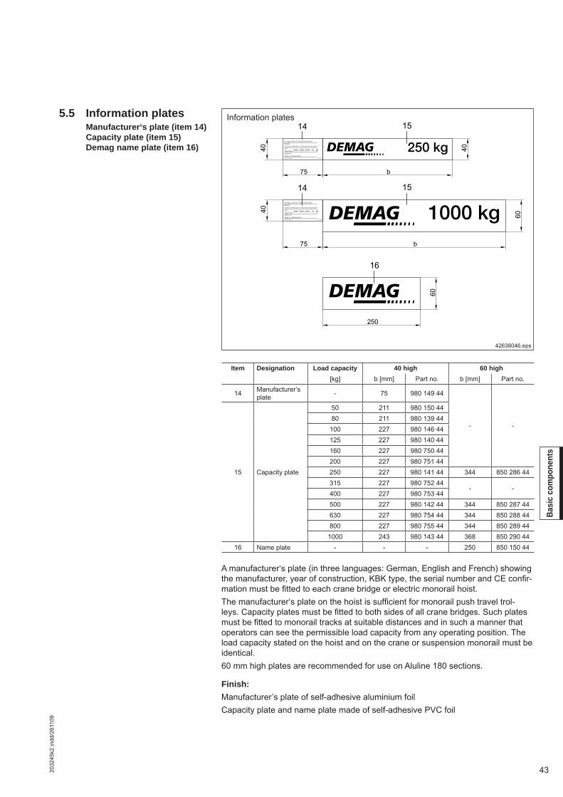
Information plates
A manufacturer‘s plate (in three languages: German, English and French) showing the manufacturer, year of construction, KBK type, the serial number and CE confi r-mation must be fi tted to each crane bridge or electric monorail hoist.The manufacturer‘s plate on the hoist is suffi cient for monorail push travel trol-leys. Capacity plates must be fi tted to both sides of all crane bridges. Such plates must be fi tted to monorail tracks at suitable distances and in such a manner that operators can see the permissible load capacity from any operating position. The load capacity stated on the hoist and on the crane or suspension monorail must be identical.60 mm high plates are recommended for use on Aluline 180 sections.
Finish:Manufacturer’s plate of self-adhesive aluminium foilCapacity plate and name plate made of self-adhesive PVC foil
42638046.eps
5.5 Information plates Manufacturer‘s plate (item 14) Capacity plate (item 15) Demag name plate (item 16)
Item Designation Load capacity 40 high 60 high[kg] b [mm] Part no. b [mm] Part no.
14 Manufacturer‘s plate - 75 980 149 44
- -
15 Capacity plate
50 211 980 150 4480 211 980 139 44
100 227 980 146 44125 227 980 140 44160 227 980 750 44200 227 980 751 44250 227 980 141 44 344 850 286 44315 227 980 752 44
- -400 227 980 753 44500 227 980 142 44 344 850 287 44630 227 980 754 44 344 850 288 44800 227 980 755 44 344 850 289 44
1000 243 980 143 44 368 850 290 4416 Name plate - - - 250 850 150 44

44 2032
45k2
.indd
/261
109
Susp
ensi
on
with suspension rodshort, adjustable
6 Track suspension
6.1 Remarks and overview The examples shown on the following page are only some of the many combina-tions possible by using standard series-manufactured suspension fi ttings.
The owner is responsible for verifi cation of superstructure/support structure.
Particularly low suspension heights are achieved by using short suspension ar-rangements.
Suspension from inclined steelwork is also possible.
On long suspension arrangements, with suspension rod lengths from approx. 600 mm upwards, undesirable pendulation of the track may occur. (This may already occur in small installations and when electric drives are used with short suspen-sions). This can be limited by fi tting longitudinal and lateral stiffeners.
For monorails and crane runways, transverse stiffeners should be provided ap-prox. every 15 m for KBK Aluline 120 and approx. every 20 m for KBK Aluline 180. One stiffener is usually suffi cient in the longitudinal direction. All crane runways must be provided with stiffeners.
Transverse and longitudinal stiffeners are of V-type design.
V-type suspension fi ttings may also replace missing suspension points in vertical suspension arrangements. Max. vertical dimension as for vertical suspension arrangements
Supporting structure
Sloping steel superstructure
Short suspension fi tting
Stiffeners
V-type suspensions
Examples
42607845.eps
Thread Load capacity 1) Suspension dimension h2 h1
ergo Short suspension fi ttingadjustable
Suspension fi ttingwith suspension rod
max.Threaded suspension rod
length[kg] [mm] [mm] 80/100 mm [m]
Aluline 120 M10 750 73 ± 4 73 ± 4 134 ± 9 2Aluline 180 M16 x 1,5 1400 115 ± 7 115 ± 7 195 ± 14 3
1) Static or alternating load
Load capacity, dimensions for suspension from I-beam superstructures, height compensation
ergo

452032
45k2
.indd
/261
109
Susp
ensi
on
42673747.eps
on anchor bolts 2) from U-bolt 1) from brackets 1)
with fl oor plate 1) drilled 1) on wood 1)
42673147.eps
Lateral stiffener Lateral stiffener 1) V-type stiffener Sloping stiffener
V-type suspension Sloping V-type suspension Sloping suspension
Examples
1) For description see document 202 976 44.2) For description see document 203 276 44.

46 2032
45k2
.indd
/261
109
Susp
ensi
on
Complete suspension fi ttings, pre-assembled(Item 30)
Upper suspension bracket A can be used on roof structures and steel profi le sec-tions; upper suspension bracket B (ends project beyond bearing surface) is only suitable for steel profi le sections.The special clamp design ensures that the bolt of the clamp is always vertical re-gardless of the beam fl ange thickness.
Upper suspension bracket S and upper suspension clamp S for steel sections with larger fl ange width for various fl ange thicknesses, see technical data sheet 203 072 44.
Higher fl ange bending stresses may occur, for example, when used on HE-A beams.
6.2 Vertical suspension on I-beams
6.2.2 Suspension with suspension rod
1) Max. girder gradient ± 1,5°
42607846.eps
41404342
26254340
1)
Section Suitable for profi le sections
I IPE HE-B (IPB)
Aluline 120Suspension bracket A 140 - 260 120 - 270 100 - 140Suspension bracket B - 220 - 450 120 - 200
Aluline 180Suspension bracket A 140 - 320 140 - 270 100 - 120Suspension bracket B 220 - 450 180 - 500 100 - 200
Section h2 m n w x z[mm] [mm] [mm] [mm] [mm] [mm]
Aluline 120 54 + h1 ± 9 M10 70 60 40 4Aluline 180 95 + h1 ± 14 M16x1,5 90 95 60 5
Section a f c d
[mm] [mm] [mm] [mm]
Aluline 120Suspension bracket A 205 66 - 142
7027
Suspension bracket B 270 110 - 210 23
Aluline 180Suspension bracket A 221 71 - 139 72 37Suspension bracket B 290 100 - 208 76 36
Classic suspensions are fl exible, ball-and-socket universal joint suspension ar-rangements featuring minimum torque transmission to roof and ceiling superstruc-tures and minimum lateral forces transmitted to the track systemErgo suspension to accommodate loads resulting from counter-forces (from han-dling devices and cranes with large overhang) with rigid suspensions, featuring rubber buffers.
6.2.1 I-beam assignment
Item Designation Suspension rod
Upper suspen-
sion bracket
Aluline 120 Aluline 180Weight Part no. Weight Part no.
h1 = [mm] Type [kg] [kg]
30
Complete suspen-sion fi tting with suspension rod
80A 2,10 855 169 44 - -B 2,33 517 729 46 - -
100A - - 4,18 855 175 44B - - 5,02 855 176 44
300A 2,23 517 730 46 4,50 517 740 46B 2,47 517 731 46 5,34 517 741 46
600A 2,42 517 732 46 4,97 517 742 46B 2,65 517 733 46 5,81 517 743 46
1000A 2,66 517 734 46 5,60 517 744 46B 2,90 517 735 46 6,44 517 745 46
Load capacity [kg] 750 1400
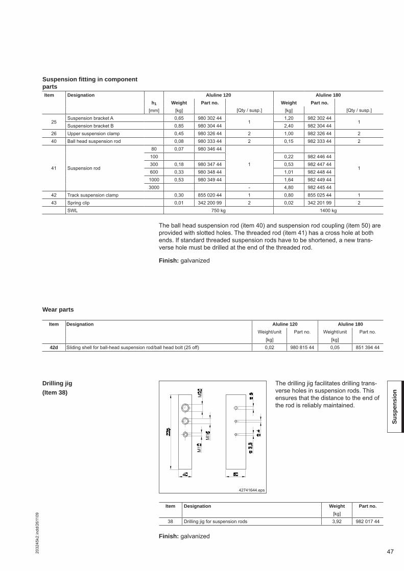
472032
45k2
.indd
/261
109
Susp
ensi
on
The ball head suspension rod (item 40) and suspension rod coupling (item 50) are provided with slotted holes. The threaded rod (item 41) has a cross hole at both ends. If standard threaded suspension rods have to be shortened, a new trans-verse hole must be drilled at the end of the threaded rod.
Finish: galvanized
Drilling jig(Item 38)
Item Designation Aluline 120 Aluline 180h1 Weight Part no. Weight Part no.
[mm] [kg] [Qty / susp.] [kg] [Qty / susp.]
25Suspension bracket A 0,65 980 302 44
11,20 982 302 44
1Suspension bracket B 0,85 980 304 44 2,40 982 304 44
26 Upper suspension clamp 0,45 980 326 44 2 1,00 982 326 44 240 Ball head suspension rod 0,08 980 333 44 2 0,15 982 333 44 2
41 Suspension rod
80 0,07 980 346 44
11
100 0,22 982 446 44300 0,18 980 347 44 0,53 982 447 44600 0,33 980 348 44 1,01 982 448 44
1000 0,53 980 349 44 1,64 982 449 443000 - 4,80 982 445 44
42 Track suspension clamp 0,30 855 020 44 1 0,80 855 025 44 143 Spring clip 0,01 342 200 99 2 0,02 342 201 99 2
SWL 750 kg 1400 kg
Item Designation Weight Part no.[kg]
38 Drilling jig for suspension rods 3,92 982 017 44
42741644.eps
The drilling jig facilitates drilling trans-verse holes in suspension rods. This ensures that the distance to the end of the rod is reliably maintained.
Item Designation Aluline 120 Aluline 180Weight/unit Part no. Weight/unit Part no.
[kg] [kg]42d Sliding shell for ball-head suspension rod/ball head bolt (25 off) 0,02 980 815 44 0,05 851 394 44
Wear parts
Finish: galvanized
Suspension fi tting in component parts

48 2032
45k2
.indd
/261
109
Susp
ensi
on
A particularly low suspension headroom can be achieved using the ball head bolt/ball head suspension rod connection arrangement with spring clip. Slotted holes facilitate height adjustment.Finish: galvanized
6.2.4 Short suspension arrangement with height adjustment
Short suspension fi tting
42607847.eps
h2
[mm]Aluline 120 73 ± 4Aluline 180 115 ± 7
Complete suspension fi ttings, pre-assembled(Item 31)
262540434442
1)
Item Designation Aluline 120 Aluline 180Weight Part no. Weight Part no.
[kg] [Qty / susp.] [kg] [Qty / susp.]
25Suspension bracket A 0,65 980 302 44
11,20 982 302 44
1Suspension bracket B 0,85 980 304 44 2,40 982 304 44
26 Upper suspension clamp 0,45 980 326 44 2 1,00 982 326 44 240 Ball head suspension rod 0,08 980 333 44 1 0,15 982 333 44 144 Ball head bolt 0,06 980 283 44 1 0,14 982 283 44 142 Track suspension clamp 0,30 855 020 44 1 0,80 855 025 44 143 Spring clip 0,01 342 200 99 1 0,02 342 201 99 1
SWL 750 kg 1400 kg
Coupling for suspension rod
42623244.eps
6.2.3 Coupling for suspension rod (Item 50)
x = Aluline 120: 0-3 Aluline 180: 0-4
43
41
50
Use couplings to connect several suspension rods.
Finish: galvanized
Item Designation Aluline 120 Aluline 180Weight Part no. Weight Part no.
[kg] [kg]50 Coupling for suspension rod 0,10 980 277 44 0,17 982 277 44
Item Designation Upper suspen-
sion bracket
Aluline 120 Aluline 180Weight Part no. Weight Part no.
Type [kg] [kg]
31Complete suspension fi tting, short, adjustable
A 2,02 855 167 44 3,98 855 173 44B 2,25 517 727 46 4,82 855 174 44
SWL 750 kg 1400 kgSuspension fi tting in component parts

492032
45k2
.indd
/261
109
Susp
ensi
on
Item Designation Aluline 120 Aluline 180Weight/unit Part no. Weight/unit Part no.
[kg] [kg]42d Sliding shell for ball-head suspension rod/ball head bolt (25 off) 0,02 980 815 44 0,05 851 394 44
Wear parts
Vertical suspension from U-sections
42671344.eps
Upper U-type suspensions can be used on U-shaped steel profi le sections (DIN 1024).The max. suspension load must be observed as specifi ed in the table:
6.3 Vertical suspension from U-sections
The free swing angle of the suspension fi tting may be limited by the girder profi le. Use stiffeners, as required, to avoid any collision during operation.
The connection between the upper ball head suspension rod and threaded rod is secured with the enclosed split sleeve (see “X”)
Edge “Y” of the suspension bracket must be in close contact with the profi le sec-tion.The ball head suspension rods, the threaded rods, the spring clip and the suspen-sion clamp must be ordered separately.
Finish: galvanized
The loads specifi ed for individual profi le sections must not be exceeded. Verifi ca-tion of the U profi le section is the responsibility of the owner.
Item Section Weight Part no. Max. suspension load GAB
Girder section
[kg] [kg]
25
Aluline 120 2 980 377 44 750 U 80 - U 220
Aluline 180 2 984 377 44
750 U 80 - U 1001000 U 120 - U 1401250 U 1601400 U 180 - U 220
h2 h5
Aluline 12020 + h1 ± 9
> track section height + 40
40
Aluline 18050 + h1 ± 14
> track section height + 65
65
XY
25
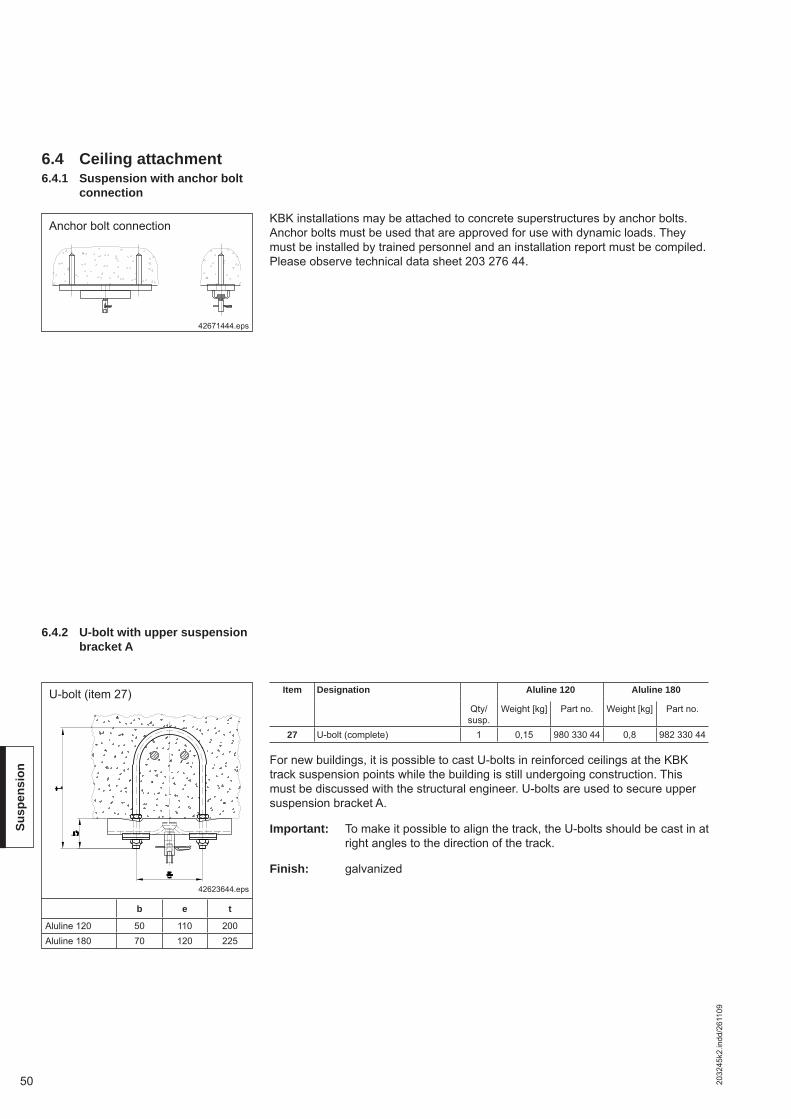
50 2032
45k2
.indd
/261
109
Susp
ensi
on
For new buildings, it is possible to cast U-bolts in reinforced ceilings at the KBK track suspension points while the building is still undergoing construction. This must be discussed with the structural engineer. U-bolts are used to secure upper suspension bracket A.
Important: To make it possible to align the track, the U-bolts should be cast in at right angles to the direction of the track.
Finish: galvanized
U-bolt (item 27)
42623644.eps
6.4.2 U-bolt with upper suspension bracket A
6.4 Ceiling attachment 6.4.1 Suspension with anchor bolt
connection
42671444.eps
KBK installations may be attached to concrete superstructures by anchor bolts. Anchor bolts must be used that are approved for use with dynamic loads. They must be installed by trained personnel and an installation report must be compiled. Please observe technical data sheet 203 276 44.
Anchor bolt connection
Item Designation Aluline 120 Aluline 180
Qty/susp.
Weight [kg] Part no. Weight [kg] Part no.
27 U-bolt (complete) 1 0,15 980 330 44 0,8 982 330 44
b e t
Aluline 120 50 110 200Aluline 180 70 120 225

512032
45k2
.indd
/261
109
Susp
ensi
on
Suspension may only be from cast-in section rails that are approved for dynamic loads.A-type upper suspension brackets are secured to section rails cast in concrete using a packing plate and 2 special bolts with nuts and tab washers. The M10 for KBK Aluline 120 and M16 for KBK Aluline 180 special bolts should be provided by the customer or can be supplied on application (specify section rail type).Ensure compliance with load-bearing capacity and correct length of special bolts.
Important: This KBK suspension fi tting must be regarded as a concentrated load on the securing section rail (low load-bearing capacity).
Finish: galvanized
Upper suspension brackets H with bore hole spacing ≥ 250 mm count as dual load suspensions.See technical data sheet 203 072 44.
6.4.3 Suspension from ceiling section rails with upper suspension bracket A
42623744.eps
Tab washer (item 32),lock nut (item 33),packing plate (item 51)
33
Cast-in section rail
51150 deep
32
1) or as indicated for cast-in section rail for up-per suspension bracket H
For tightening torque M see data referring to cast-in section rail
d m 1)
Aluline 120 70 M10Aluline 180 80 M16
Item Designation Aluline 120 Aluline 180
Qty/susp.
Weight[kg]
Part no. Weight[kg]
Part no.
32 Packing plate 2 0,1 980 429 44 0,21 984 329 4433 Lock nut 2 - 334 610 44 - 334 614 44
51 Packing plate for upper sus-pension bracket 1 1,6 984 088 44 1,6 984 088 44

52 2032
45k2
.indd
/261
109
Susp
ensi
on
42623844.eps
In existing concrete buildings it is impossible to fi t supporting steel without losing headroom. In such cases it is possible to make a hole in the ceiling at the suspen-sion point and to use a fl oor fi xture plate for the ball head suspension rod with the cover for the fl oor fi xture plate. The connection between the suspension rod and the ball head suspension rod is often no longer accessible for maintenance and the two rods must be secured relative to each other by a split sleeve instead of a spring clip. Arrangement of these fi ttings, the loads to which they are subjected and dimension X should be agreed with the structural engineer or architect respon-sible.
Finish: galvanized
Nut for suspension rod (item 39)
42623944.eps
A-type upper suspension brackets can also be secured to solid ceilings by using two suspension rods with tab washers. The transmission of forces to the concrete ceiling must be agreed with the structural engineer.
6.4.4 Suspension with fl oor fi xture plate and cover
6.4.5 Suspension with upper suspension bracket A and suspension rods or positive anchors
25 3932
39 3241
363537
Item Designation Aluline 120 Aluline 180Weight
[kg]Part no. Weight
[kg]Part no.
35 Floor slab 0,2 980 336 44 0,4 982 336 4436 coverage 0,2 980 338 44 0,2 982 338 44
37Split sleeve 3 x 18 - 345 095 99 - -Split sleeve 4 x 26 - - - 345 008 99
Item Designation Aluline 120 Aluline 180Part no. Part no.
39 Nut for suspension rod 150 509 99 150 678 99
b g m
Aluline 120 60 35 M10Aluline 180 85 50 M16 x 1,5
d D t w
Aluline 120 40 110 25 35Aluline 180 60 150 28 60
Floor fi xture plate (item 35),cover for fl oor fi xture plate (item 36),split sleeve (item 37)

532032
45k2
.indd
/261
109
Susp
ensi
on
42624044.eps
h1 = suspension rod length1) no spring clip here
V-type suspensions are fi tted as shown in the diagrams. V-type hinged suspension bracket (item 47) and V-type upper suspension bracket (item 46) are connected to each other by suspension rod strainer (item 48), suspension rod (item 41) and hinged end piece (item 49). Each bolted connection with a hinged end piece must be secured with a spring clip (item 43).The maximum permissible loads correspond to those for vertical suspension arrangements.
Finish: galvanized
6.5 V-type suspension
2646
43
49
41
48
47
1)
Item V-type suspension fi tting, parallel or perpendicular h1 Aluline 120 Aluline 180
Weight Part no. Weight Part no.
[mm] [kg / unit] [Qty / susp.] [kg / unit] [Qty / susp.]
26 Upper suspension clamp 0,45 980 326 44 4 1,00 982 326 44 4
40 Ball head suspension rod 0,08 980 333 44 0,15 982 333 44
41 Suspension rod
80 0,07 980 346 44
22
100 0,22 982 446 44
300 0,18 980 347 44 0,53 982 447 44600 0,33 980 348 44 1,01 982 448 441000 0,53 980 349 44 1,64 982 449 44
3000 - 4,80 982 445 44
43 Spring clip 0,01 342 200 99 2 0,02 342 201 99 246 V-type upper suspension bracket B 1,39 980 360 44 2 3,20 984 075 44 2
47 V-type suspension bracket 1,24 855 160 44 2,56 855 166 44 1
54 Pin with BoClip for third hinged end piece 0,08 851 305 44 0,16 851 317 44
48 Suspension rod strainer 0,29 980 310 44 2 0,85 984 085 44 249 Hinged end piece 0,10 980 315 44 2 0,30 984 083 44 2
SWL 750 kg 1400 kg
Section h4 m q u
[mm] [mm] [mm] [mm]
Aluline 120 h1 + 155 ± 30 M10 40 51Aluline 180 h1 + 220 ± 40 M16 x 1,5 55 69

54 2032
45k2
.indd
/261
109
Susp
ensi
on
Stiffeners are fi tted as shown in the diagrams. V-type hinged suspension bracket (item 47) and V-type upper suspension bracket (item 46) are connected to each other by suspension rod strainer (item 48), suspension rod (item 41) and hinged end piece (item 49). Each bolted connection with a hinged end piece must be se-cured with a spring clip (item 43).
Finish: galvanized
40472446.eps
Crane runway stiffener, perpendicular direction Track stiffener, longitudinal direction
6.6 Stiffener
2625434041
49
47
46
49
48
1)
Not permissible for any profi le sections
42624145.eps
Section j k p s u v
[mm] [mm] [mm] [mm] [mm] [mm]
Aluline 120 165±15 50 60 20 51 h1+65±4Aluline 180 235±20 65 90 25 69 h1+100±7
Item Stiffener, parallel or perpendicular h1 Aluline 120 Aluline 180Weight Part no. Weight Part no.
[mm] [kg / unit] [Qty / susp.] [kg / unit] [Qty / susp.]
25Suspension bracket A 0,65 980 302 44
11,20 982 302 44
1Suspension bracket B 0,85 980 304 44 2,40 982 304 44
26 Upper suspension clamp 0,45 980 326 44 4 1,00 982 326 44 440 Ball head suspension rod 0,08 980 333 44 1 0,15 982 333 44 1
41 Suspension rod
80 0,07 980 346 44
1+11+1
100 0,22 982 446 44300 0,18 980 347 44 0,53 982 447 44600 0,33 980 348 44 1,01 982 448 441000 0,53 980 349 44 1,64 982 449 443000 - 4,80 982 445 44
43 Spring clip 0,01 342 200 99 3 0,02 342 201 99 346 V-type upper suspension bracket B 1,39 980 360 44 1 3,20 984 075 44 147 V-type suspension bracket 1,24 855 160 44 2,56 855 166 44 154 Pin with BoClip for third hinged end piece 0,08 851 305 44 0,16 851 317 44
47a Filler plates for sloping surface - - - 0,60 516 833 4648 Suspension rod strainer 0,29 980 310 44 1 0,85 984 085 44 149 Hinged end piece 0,10 980 315 44 2 0,30 984 083 44 2
SWL 750 kg 1400 kg
h1 = suspension rod length1) no spring clip here

552032
45k2
.indd
/261
109
Susp
ensi
on
Pin axis parallel to V-type upper suspension bracket1. May slope in this plane 2. Additional sloping plane is not possible
V-type upper suspension brackets are fi tted with a pin with split sleeves (no hinged end piece).
V-type upper suspension brackets arefi tted to the superstructure in the same way as vertical suspension arrangements (e.g. with upper suspension clamps).V-type upper suspension brackets are the same size as upper suspension bracket B (the ends are higher).Upper suspension bracket A is not used for stiffeners/V-type suspensions because the girders which fi t upper suspension bracket A do not always absorb the lateral and tension forces. For smaller girders: Adapters available on request.The V-type upper suspension bracket is designed for connecting one suspension rod by means of a hinged end piece (item 49) (pin axis either parallel or perpen-dicular to V-type upper suspension bracket). If two or more connections are fi tted, a corresponding number of V-type upper suspension brackets must be fi tted next to each other.The pin axis of the V-type upper suspension bracket must always be horizontal and parallel to the pin axis of the V-type hinged suspension bracket (item 47) and perpendicular to the suspension rod axis. V-type upper suspension brackets on sloping superstructures must be anchored against movement. If a V-type upper suspension bracket is not fi tted to steel sections, the packing plate (item 51) must be used.
Finish: galvanized
Clamp section with V-type upper suspension bracket B for steel sections with larger fl ange width for various fl ange thicknesses, see technical data sheet 203 072 44.
42624244.eps
6.7 Components for V-type suspension/stiff-ener arrangement
6.7.1 V-type upper suspension bracket (item 46)
Possible arrangements
Pin axis perpendicular to V-type upper suspension bracket1. May slope in this plane 2. Additional sloping plane is not possible
46
46
Section c q r y
[mm] [mm] [mm] [mm]
Aluline 120 125 40 45 40Aluline 180 150 55 65 50
Item Designation Aluline 120 Aluline 180
Weight Part no. Weight Part no.
[kg] [kg]
46 V-type upper suspension bracket B 1,39 980 360 44 3,20 984 075 44

56 2032
45k2
.indd
/261
109
Susp
ensi
on
If the V-type upper suspension bracket is not fi tted to steel sections, packing plate (item 51) must be used. This is to ensure that the V-type upper suspension bracket is properly fi tted to solid ceilings, ceiling section rails, etc.Connections with U-bolt on request
Packing plate for upper suspension bracket
42624544.eps
6.7.2 Packing plate for upper suspension bracket
(Item 51)
51
Item Designation Weight Part no.
[kg]
51 Packing plate for upper suspension bracket 1,79 984 088 44
6.7.3 V-type hinged suspension bracket
(Item 47)
Possible arrangements
The V-type hinged suspension bracket (item 47) consists of a suspension bracket, V-hinge and two pins with split sleeves.The V-type hinged suspension bracket is designed for a maximum of three sus-pension rod connections (suspension rod strainer or hinged end piece). On a V-type suspension arrangement, the rods are fi tted to the outer holes, on a lateral stiffener to the centre and one outer hole.The V-type hinge can be adjusted in the suspension bracket to any angle in rela-tion to the track, however, the pin axis must always be perpendicular to the sus-pension rod axis. Where three hinged end pieces are used, one additional pin with a BoClip must be ordered.
Item Designation Aluline 120 Aluline 180Weight Part no. Weight Part no.
[kg] [kg]47 V-type hinged suspension bracket 1,24 855 160 44 2,56 855 166 4454 Pin with BoClip for third hinged end piece 0,08 851 305 44 0,16 851 317 44
47
42624146.eps
h1 = suspension rod lengthSection p s u v
[mm] [mm] [mm] [mm]Aluline 120 60 20 51 h1+65±4Aluline 180 90 25 69 h1+100±7

572032
45k2
.indd
/261
109
Susp
ensi
on
6.7.4 Spring clip (Item 43) Suspension rod
strainer (Item 48) Hinged end piece (Item 49)
Suspension rod strainer (item 48) and hinged end piece (item 49) together with one suspension rod connect the upper and lower parts of the V-type suspension fi tting/suspension fi tting with stiffener/sloping suspension fi tting. The suspension rod strainer consists of a strainer nut, hinged end piece with left-hand thread, re-taining cap and a spring clip.If the length of the suspension rods can be determined exactly, it is also possible to suspend the track without a suspension rod strainer. In this case, a hinged end piece (item 49) is used at the top and bottom, and the V-type upper suspension brackets can be pulled apart to level the track.Length of the suspension rod thread in the hinged end piece:Aluline 120: 20 mm Aluline 180: 25 mmLength of the left-hand thread of the hinged end piece and of the suspension rod thread in the strainer nut:Aluline 120: 45 mm Aluline 180: 60 mm at full ± adjustment.One spring clip (item 43) is required for every connection between a hinged end piece (item 49) and suspension rod (item 41). Only the connection between the suspension rod strainer and suspension rod does not feature a spring clip.
42624445.eps
h1 = suspension rod length1) no spring clip here
Possible arrangements
4349411)48
Section h4 j k
[mm] [mm] [mm]
Aluline 120 h1 + 155 ± 30 165 ± 15 60Aluline 180 h1 + 220 ± 40 235 ± 20 65
Item Designation Aluline 120 Aluline 180
Weight Part no. Weight Part no.
[kg] [kg]
43 Spring clip 0,01 342 200 99 0,02 342 201 9948 Suspension rod strainer 0,29 980 310 44 0,85 984 085 4449 Hinged end piece 0,10 980 315 44 0,30 984 083 44

58 2032
45k2
.indd
/261
109
Susp
ensi
on
6.8 Determining suspen-sion rod length h1 for V-type suspensions and stiffeners
Suspension rod length h1 can be determined depending on:- KBK section,- Steel structure alignment,- Distance between lower edge of steel structure and upper edge of KBK section (dimension h2),- Opening angle α.
The following simplifi ed formulas may be used, since the suspension rod strainer offer as wide range for adjustment.
Aluline 120 → h1 =h2 - 95
- 155cos α
Aluline 180 → h1 =h2 - 135
- 220cos α
6.7.5 Wall fi xture
Item Designation Aluline 120 Aluline 180Weight [kg] Part no. Weight [kg] Part no.
34 Hinged block/connection block 0,2 980 272 44 0,46 850 399 4454 Pin with BoClip 0,08 851 305 44 - -
The hinged block/connection block can be used as a wall anchorage for a stiffener arrangement, see also section 6.6.
42766944.eps
Aluline 120 Aluline 180
42624046.eps
α
q r u
Aluline 120 40 45 51Aluline 180 55 65 69

592032
45k2
.indd
/261
109
Susp
ensi
on
42604845.eps
ergo suspension fi tting
Aluline 120 Aluline 180
KBK Aluline ergo suspensions are complete suspension fi ttings, i.e. they already include upper suspension brackets, upper suspension clamps and track suspension clamps (upper suspension brackets and track suspension clamps are pre-assembled).KBK ergo suspension fi ttings can accommodate loads resulting from the use of handling equipment and cranes with a large overhang.The use of a rubber element allows the suspension fi tting to accommodate forces acting in all directions and to adapt to defl ection in the runway. Furthermore, the rubber element provides additional protection from impacts for the superstructure and the KBK Aluline installation.Upper suspension bracket A can be used on roof structures and steel profi le sec-tions; upper suspension bracket B (ends project beyond bearing surface) is only suitable for steel profi le sections.
Higher fl ange bending stresses may occur, for example, when used on HE-A beams.
The KBK Aluline ergo suspension fi tting headroom corresponds to the short classic suspension fi tting. Larger suspension heights must be adapted to suit the steel structure.Short classic suspension fi ttings and ergo suspension fi ttings can be used alter-nately.KBK ergo suspension fi ttings must be used at runway ends.
Finish: galvanized
Item Designation Aluline 120 Aluline 180
Weight Part no. Weight Part no.
[kg] [kg]
31e
ergo suspension fi tting A 4,25 855 031 44 11,0 855 033 44ergo suspension fi tting B 12,5 855 034 44
SWLLoad K 750 kg 1400 kgLoad V 100 Kg 200 kgLoad H 100 kg 200 kg
Section Upper suspension bracket a f c d
[mm] [mm] [mm] [mm]
Aluline 120 Suspension bracket A 221 71 - 139 72 37
Aluline 180Suspension bracket A 221 71 - 139 222 37Suspension bracket B 290 100 - 208 226 36
6.9 ergo suspension fi t-ting
(Item 31e) with upper suspension bracket A or B on steel profi le sections
h2
[mm]
Aluline 120 73 ± 4Aluline 180 115 ± 7

60 2032
45k3
.indd
/261
109
Trol
leys
7 Trolley combinations
42604945.epsAluline 120 Aluline 180
Quiet-running Aluline trolleys are fi tted with four plastic wheels mounted in perma-nently lubricated antifriction bearings and two special horizontal support rollers. The trolley side cheeks project beyond the travel wheels as protection against collision damage.The traction resistance of a loaded trolley is < 0,4 % of the attached load with constant displacement.Connection possibility for link bars, spacer bars, etc. with link (item 61)Temperature range:0 °C to +50 °CFinish: black (RAL 9005), steel
42605044.eps
KBK ergo trolley
Aluline 120 Aluline 180
KBK ergo trolleys can accommodate forces in all axes.Forces acting against gravity are accommodated by counter-pressure rollers, hori-zontal forces are accommodated via the lateral guide rollers.KBK ergo trolleys are rigidly bolted to end carriages or crab frames.The traction resistance of a loaded trolley is < 0,4 % of the attached load with constant displacement.Temperature range: 0 °C to +50 °CFinish: black (RAL 9005), steel ergo connecting element for Aluline 180: aluminium
KBK classic trolleys
KK
Item Designation Aluline 120 Aluline 180
Load Weight Part no. Load Weight Part no.
[kg] [kg] [kg] [kg]
55 Travel unit 300 1,2 855 050 44 600 2,2 855 080 44
Item Designation Aluline 120 Aluline 180
Load K Vert. load V Hor. load H Weight Part no. Load K Vert. load V Hor. load H Weight Part no.
[kg] [kg] [kg] [kg] [kg] [kg] [kg] [kg]
55e KBK ergo trolley 300 100 50 1,3 855 055 44 600 200 100 2,6 855 075 44
7.1 Single trolleys7.1.1 Classic trolleys (Item 55)
7.1.2 Ergo trolleys (Item 55)

612032
45k3
.indd
/261
109
Trav
el u
nits
KBK classic load bar
Load bar
Aluline 120
Aluline 180
A double trolley is created by joining two trolleys with a load bar. Holes drilled in the ends of Aluline 180 load bars are provided for fi tting spacer bars and link bars, they are not designed for connecting loads.Use the long suspension eye for DC and DK hoists.Finish: black (RAL 9005), steel
Item Designation Aluline 120 Aluline 180
Load Weight Part no. Load Weight Part no.
[kg] [kg] [kg] [kg]
57 Load bar 600 1 980 305 44 1200 2 982 305 44
7.2 Double trolleys
42605145.eps
Item Designation Aluline 120 Aluline 180Weight/unit Part no. Weight/unit Part no.
[kg] [kg]54 Pin with BoClip 0,08 851 305 44 0,16 851 317 44
Wearing parts for single and double trolleys

62 2032
45k3
.indd
/261
109
Trol
leys
Rigid crane trolleys make it possible to build parallel-running single and double-girder cranes with a direct connection to the crane girder.Double-girder cranes can be fi tted with normal crab frames, or in order to obtain more favourable hook dimensions, with raised crab frames. Raised crabs run be-tween the rails.Two frames and two crane end carriages are required for each crane.Link bars, spacer bars or buffer fi ttings can be connected using the single-trolley link or load bar (see chapters 13 and 14).Length of stiffener on the crane: Aluline 120: 495 mm; Aluline 180: 640 mm.Frame and crane traverse not including trolleys and load bars.
42605647.eps
Frame for double-girder crane
7.3.1 Frame for double-girder crane (Item 63)
7.3 Classic crane end car-riages
Item Designation Crane section eKT lKa Max. hoist load Weight Part no.
[mm] [mm] [kg] [kg]
63 Frame for double-girder craneAluline 120
550 550500 5,5 855 115 44
Aluline 180 1000 8,5 855 120 44

632032
45k3
.indd
/261
109
Trav
el u
nits
Rigid single-girder crane traverse
Finish: black (RAL 9005), steel
Check trolley loads.
Example for ordering:2 off Aluline 180 rigid double-girder crane traverse, eKT = 1000, LKa = 550
Rigid double-girder crane traverse
Item Designation Crane section eKT lKa Max. hoist load Weight Part no.
[mm] [mm] [kg] [kg]
62
Rigid single-girder crane traverseAluline 120
1000500
14 517 672 46
Rigid double-girder crane traverse1000 550 - 610 16
517 674 461200 762 - 915 18
Rigid single-girder crane traverse
Aluline 180
1000
1000
25 517 678 46
Rigid double-girder crane traverse
1000 550 - 762 26
517 680 461250 915 - 1000 301500 1220 371750 1524 41
42605648.eps
7.3.2 Rigid single-girder crane traverse,
Rigid double-girder crane traverse
(Item 62)

64 2032
45k3
.indd
/261
109
Trol
leys
The end carriage length required depends on the crane span and the load. Wheel base eKT of the end carriage should not be less than 1/8 of crane span lKr.Longer end carriages should be used to achieve greater suspension distances and reduce suspension loads.The permissible maximum loads on KBK ergo trolleys determine the maximum load on the end carriages. The given stated apply only to centrally-acting forces transmitted free of moment.For offset loads or if moments are transmitted, the maximum permissible load of -100 kg to +300 kg for Aluline 120 and -200 kg to +600 kg for Aluline 180 must not be exceeded on the individual trolleys.
42605744.eps
Aluline 180 ergo single-girder crane traverse
Crane runways and crane girders are made of Aluline 180.The trolleys are an integral part of the end carriage.Aluline 120 ergo should not be used for rigid single-girder cranes and single-girder crane traverses.Finish: black (RAL 9005), steelExample for ordering:2 off KBK Aluline 180 ergo single-girder crane traverse,eKT = 550 mm
Item Standard dimension Aluline 180 track section
eKT Max. load Weight
[mm] [kg] [kg]
62e
450
- 400 to +1200
25,0550 26,7650 28,4800 31,0
1050 34,41250 37,7
7.4 Ergo crane end car-riages
7.4.1 Single-girder crane end carriage
(Item 62e)Aluline 180 ergo

652032
45k3
.indd
/261
109
Trav
el u
nits
42605844.eps
Aluline 120 ergo double-girder crane traverse
Crane runways and crane girders are made of Aluline 120.The trolleys are an integral part of the end carriage.
Finish: black (RAL 9005), steel
Item Standard dimension Aluline 120 runway and crane section
lKa eKT Max. load Weight
[mm] [mm] [kg] [kg]
62e
550 650
- 200 to +600
8,9610 750 9,3650 750 9,3762 900 9,9800 900 9,9915 1100 10,7
7.4.2 Double-girder crane end carriage
(Item 62e)Aluline 120 ergo
Aluline 180 ergo
42605944.eps
Aluline 180 ergo double-girder crane traverse
Crane runways are made of Aluline 180, crane girders of Aluline 120 or Aluline 180.The trolleys are an integral part of the end carriage.
Finish: black (RAL 9005), steelExample for ordering: 2 off KBK Aluline 180 ergo double-girder crane traverse, lKa = 610 mm, Aluline 180 crane profi le section.
Item Standard dimension Aluline 180 track sectionAluline 120 crane
sectionAluline 180 crane
section
lKa eKT Max. load Weight Weight
[mm] [mm] [kg] [kg] [kg]
62e
550 800
- 400 to +1200
34,0 36,5610 900 35,7 38,2650 900 35,7 38,2762 1050 38,4 40,9800 1050 38,4 40,9915 1250 41,8 44,3
1000 1250 41,8 44,3

66 2032
45k3
.indd
/261
109
Trol
leys
7.4.3 Tandem crane end carriage (Item 62e)
42606044.eps
Aluline 180 ergo tandem crane end carriage
Crane runways and crane girders are made of Aluline 180.The trolleys are an integral part of the end carriage.Tandem end carriages are used when crab span dimension lKa is > 1000 mm, or the permissible crane trolley load for a double-girder crane end carriage is ex-ceeded.The total length of the tandem crane end carriage results from 2 x lKa – 50 mm.Tandem crane end carriages consist of two single-girder crane traverses and a spacer bar.Single-girder crane traverses are supplied pre-assembled complete with trolleys. During fi nal assembly they only have to be connected to the spacer bar.The permissible maximum loads on KBK ergo trolleys determine the maximum load on the end carriages. The given stated apply only to centrally-acting forces transmitted free of moment.For offset loads or if moments are transmitted, the permissible maximum load of -400 kg and +1200 kg on the individual single-girder crane traverses must not be exceeded.Finish: black (RAL 9005), steelExample for ordering:2 off KBK Aluline 180 ergo tandem crane end carriage, lKa = 800 mm
Item Standard dimension Aluline 180 runway and crane section
lKa eKT Max. load Weight
[mm] [mm] [kg] [kg]
62e800 450
- 2 x 400 to + 2 x 120051,5
1000 650 58,31250 900 66,9
Aluline 180 ergo

672032
45k3
.indd
/261
109
Trav
el u
nits

68 2032
45k3
.indd
/261
109
Mon
orai
l tro
lley
8 Monorail trolley for special hoists
8.1 Low-headroom frame for monorail travelling hoists
Longer hook paths can be obtained for a given rail height by using the low-head-room frame for monorail hoists.Further information on request.
8.2 Load bar for DS-1 rope winch and D-SH SpeedHoist
(Item 68)
The load bar is used for fi tting DS-1 rope winch and D-SH SpeedHoist lifting appli-ances. The single-trolley link can be fi tted.The load bar is suitable for trolleys: Aluline 120 and Aluline 180
Finish: Load bar RAL 9005 (black)
42671645.eps
Item Designation Weight Part no.
[kg]
68 Load bar for DS-1 rope winch and D-SH SpeedHoist 2,2 851 195 44

692032
45k3
.indd
/261
109
Mon
orai
l tro
lley
In KBK applications, rope balancers are fl exibly connected to trolleys using a load bar.The load bar is symmetrical and is supplied with an anchorage point for the power supply on the left as standard. The anchorage point can be arranged on opposite side possible, if required. The anchorage point is used to accommodate hose bracket set 2.The load bar is suitable for trolleys: Aluline 120 and Aluline 180The following values are applied for specifying the track and crane:D-BP 55 : K = 80 kgD-BP 110 : K = 160 kg
Finish: Load bar RAL 9005 (black), pin and washers galvanized
8.3 Load bar for D-BP 55/110 rope balancer
(Item 68)
42639744.eps
The washers are only required for Aluline 180.
Swivel unit (order no.: 773 260 44)consisting of: rope wedge connection and swivel unit mounted on bearings
Up/down control Manual force control Single-load balance control systemDouble-load balance control system
Single-load balance control system incl. swivel unitDouble-load balance control system incl. swivel unit
Installation dimensionsProfi le section: Aluline 120 and Aluline 180
42578446.eps
Up/down control
c / h2
Manual force control
c / h2
Single-load (double-load)
balancer control
c / h2
Single-load (double-load)
balancer controlincl. swivel unit
c / h2D-BP 55 445 / 520 825 / 900 410 / 485 525 / 600D-BP 110 465 / 540 845 / 920 430 / 505 545 / 620
Item Designation Weight SWL Part no.
[kg] [kg]
68 Load bar for D-BP 55/110 rope balancer 1,85 230 984 685 44
Balancer dimensions

70 2032
45k3
.indd
/261
109
Crab
9 Crab
Aluline 120 or 180 crab frames fi tted with four trolleys and the hoist form a double-rail crab for double-rail tracks or double-girder cranes.Only the normal crab frame can pass under crane traverses.Travel drives are fi tted inside the crab frame for Aluline 120, and can be fi tted both inside and outside the crab frame for Aluline 180. The drive motor must face out-wards and the hoist motor must face the drive.All hoists must be used with the long suspension eye.
Finish: black (RAL 9005), steel
42605545.eps
Aluline 120 crab frame
Aluline 180 crab frame
Dimension H DKM 1DKM 2 (+10) DKUN 1 DKUN 2 DKUN 5
Reeving 1/1 2/1 1/1 2/1 1/1 2/1
Aluline 120 625 250 305 250 310 290 360 Aluline 180 585 205 260 205 265 245 315
Item Designation Aluline 120 Aluline 180
Load Weight Part no. Load Weight Part no.
[kg] [kg] [kg] [kg]
78 Crab frame 600 13,0 980 600 44 1200 18,4 855 110 44
9.1 Crab frame (Item 78)
Dimension H DCM 1 DCM 2 DCM 5 DC 1 DC 2 DC 5 DC 10Reeving 1/1 Aluline 120 568 568 613 238 238 283 - Aluline 180 523 523 568 193 193 238 343
Item Designation Aluline 120/180Weight/unit Part no.
[kg]54 Pin with BoClip 0,18 851 318 44
Wearing parts on the hoist support pin

712032
45k3
.indd
/261
109
Crab
9.2 Raised crab frame (Item 77)
Raised crab frames utilise the space between the crane girders of double-girder cranes and make it possible to achieve a minimum dimension H. However, the crab frame cannot pass under the crane runway, spacer bars or crane traverses.A solution is available with the maximum possible height for every chain hoist type and application (profi le section, load). If this is not possible due to obstacles on site, there are alternatives for DC 5/10.Electric travel drives are arranged inside the crab frame.All hoists must be used with the long suspension eye.
Finish: black (RAL 9005)
Item SectionMax. load
for alternative 1) HB H HA BKa B1 Weight Part no.
Hoist unit DC 1/2 DC 5 DC 10 1/1
[kg] [mm] [mm] [mm] [mm] [mm] [mm] [mm] [kg]
77
Aluline 120 600DC 1/2 DC 5 319 45 97 -
27 600 40015,7 517 890 46
DC 5 - 371 - 45 - 16,7 517 900 46
Aluline 180 1200DC 1/2 DC 5/10 320 44 96 185
32 700 51026,7 517 910 46
DC 5 DC 10 372 - 44 133 28,7 517 920 46DC 10 - 461 - - 44 30,9 517 930 46
42740744.eps
1) if the unit cannot be raised to the maximum position
Item Designation Aluline 120/180Weight/unit Part no.
[kg]54 Pin with BoClip 0,18 851 318 44
Wearing parts on the hoist support pin

72 2032
45k3
.indd
/261
109
Crab
Aluline ergo crab frame(Item 78e)
42606144.eps
Aluline 120 ergo crab frame
Aluline 180 ergo crab frame
Wheel base eKa and crab span dimension lKa are equal.The trolleys are an integral part of the crab frame.The crab frame is pre-assembled complete with trolleys.The maximum permissible loads on the KBK ergo trolleys determine the maximum load on the crab frame. The given stated apply only to centrally-acting forces trans-mitted free of moment.For offset loads or if moments are transmitted, the maximum permissible load of - 100 kg to +300 kg for Aluline 120 and -200 kg to +600 kg for Aluline 180 must not be exceeded on the individual trolleys.The crab frame angle strut distance a depends on the handling devices to be con-nected to the crab frame.Specify distance a in the order.Finish: black (RAL 9005), steelExample for ordering: 1 off Aluline 180 ergo crab frame, lKa = 915 mm, eKa = 1000 mm Distance a = . . . . mm
Item Crab frame lKa eKa Max. load Weight
[mm] [mm] [kg] [kg]
78e
Aluline 120
550 550
600
19,1610 650 21,0650 650 21,3762 800 24,3800 800 24,6915 1000 29,0
Aluline 180
550 550
1200
64,0610 650 66,9650 650 67,5762 800 72,1800 800 72,7915 1050 78,3
1000 1050 79,61250 1250 88,3
9.3 Ergo crab trolley

732032
45k3
.indd
/261
109
Cran
e co
mpo
nent
s
Dimensions
42606845.eps
Aluline 120
Aluline 180
42605344.epsAluline 120 Aluline 180
Crane suspension eye (item 75)
The crane suspension eye connects crane girders with the trolley or the load bar of the runway girder. Due to the ball-and-socket type mounting of the suspen-sion eye, KBK Aluline single-girder cranes can adopt a diagonal position. They can, therefore, also travel on converging crane runways. The suspension eye and clamp are irreversibly joined before leaving the factory and must not be separated.Crane suspension eyes should not be used as a swivel joint.
Finish: Galvanised steel
Item Designation Aluline 120 Aluline 180
Max. load Weight Part no. Max. load Weight Part no.
[kg] [kg] [kg] [kg]
75 Crane suspension eye 600 0,7 855 036 44 1400 1 855 038 44
10 Crane suspension eye

74 2032
45k3
.indd
/261
109
Trav
el d
rives
11 Travel drives for crabs and cranes
RF 125 travel driveElectrically drivenAluline 120 / Aluline 180
RF 100 travel drivePneumatically drivenAluline 120 / Aluline 180
DRF 200 travel driveElectrically drivenAluline 180
42607946.eps
11.1 RF 100 PN friction wheel travel drive
(Item 70)
The RF 100 PN friction wheel travel drive is a pneumatic drive unit specially de-veloped for handling equipment duty and loads up to 500 kg. The output of the pneumatic travel motor is transmitted to the bottom fl ange of the rails by means of a friction wheel.The drive is controlled pneumatically or electrically and is mainly intended to be used as a starting help.
42607244.eps
11.1.1 Travel drive with disengaging cylinder
(Item 70)
Disengaging cylinder
(295 with control)
Friction wheelLower edge KBK
BSP 1/4“
The friction wheel is pressed against the bottom fl ange of the rail by means of a pneumatic cylinder only when the motor is also supplied with compressed air. This enables the connected trolley to be moved manually when no pressure is applied.
Reversible oil-free air motorTravel speed Rated speed Scope Operating
pressureRecommended operating pres-
sure
Air demand at 4 bar
CDF Max. displaceable load
[m/min] [m/min] [W] [bar] [bar] [l/s] [%] [kg]approx. 10 - 50 20 80 3 - 6 approx. 4 4,5 50 500
Technical data
Item Designation Weight Part no.
[kg]
70 RF 100 PN with disengaging cylinder 7,3 851 078 44

752032
45k3
.indd
/261
109
Trav
el d
rives
RF travel drives with a disengaging cylinder must be fi tted with a counterwight if an articulated link bar is used.Finish: black (RAL 9005)
42543844.eps
CounterweightCounterweight
Item Designation Weight Part no.
[kg]
70a Counterweight 4,5 851 205 44
11.1.2 Counterweight (Item 70a)
11.1.3 Travel drive with pressure spring
(Item 70)
The friction wheel is permanently pressed against the bottom fl ange of the rail by means of a pressure spring. The crane or trolley can be moved within certain limits by pushing the load.
(295 with control)Lower edge KBK
BSP 1/4“
Pressure spring
Friction wheel
42607144.eps
Item Designation Weight Part no.
[kg]
70 RF 100 PN with pressure spring 7,2 851 079 44

76 2032
45k3
.indd
/261
109
Trav
el d
rives
11.1.4 RF 100 PN controls
RF pneumatic equipment base block(Item 113)
42544344.eps
Pneumatic control, pneumatic valve(Item 114)
Standard connection plate for ISO 1 valves.
Speed adjustable by means of throttles A and B.
The motor and pneumatic block can also be fi tted to the other side.
42544244.eps
42544544.eps
The pneumatic elements are fi tted and connected to the hoses on the same mounting panel.
The 5/3-way valve has the function to close, open or divert compressed air routes. The 5/3 way-function comprises fi ve connections and three switch positions. Con-nection 1 is the input for compressed air. Connections 2 and 4 are the compressed air outputs and connections 3 and 5 are used for venting.
42544444.eps
AB
Item Designation Weight Part no.
[kg]
113 RF pneumatic equipment base block 1,55 851 201 44
Item Designation Weight Part no.
[kg]
114 Pneumatic valve 0,39 343 791 44

772032
45k3
.indd
/261
109
Trav
el d
rives
Electrical control(Item 115)
42544744.eps
The unit consists of: - Solenoid valve - Magnet coil 24 VDC or 230 VAC (2 off) - Standard socket (2 off)
42544644.eps
Magnet valve Magnet coil
Socket can be turned 90°
Pg 9
Example for ordering
RF 100 PN travel drive with disengaging cylinder, suitable for Aluline 180 with RF pneumatic base block as well as pneumatic valve with 5/3-way function.
Item Designation Part no.1 Trolley with rigid link bar 270, Aluline 180 855 096 442 Counterweight 851 205 443 RF 100 PN 851 078 444 base block 851 201 445 Pneumatic valve 343 791 44
42672045.eps
Item Designation Rated voltage Weight Part no.
[kg]
115 Electrical control24 VDC 0,62 851 203 44230 VAC 0,62 851 204 44
1
2
3
5
4
1
2
3
5
4

78 2032
45k3
.indd
/261
109
Trav
el d
rives
11.2 RF 125 friction wheel travel drive
(Item 70)
Technical data DC motor with E 22 worm gearboxTravel speed
Scope CDF Voltage Frequen-cy
Max. displace-able hoist load incl. Dead load
Weight Part no.
[m/min] [W] [%] [V] [Hz] [kg] [kg]
7/27 1) 50/200 20/40 3 ~ 220-480 50/60 2200 5 716 590 45
11.2.1 Drive data
42670546.eps
1) By programming the parameters can be changed to: - max. 8/33 m/min with partial load - min. 3/16 m/min
The RF 125 friction wheel travel drive is specially developed for crane require-ments with regulated acceleration and braking for loads up to 2000 kg and inclines up to 1%.
Finish: blue (RAL 5009)
The output of the pneumatic travel motor is transmitted to the bottom fl ange of the rail by means of a friction wheel. The friction wheel is pressed against the bottom fl ange of the rail by means of a pressure spring.A permanent-fi eld DC worm geared motor serves as the drive motor.The speed of DC motors can be controlled very well, enabling smooth acceleration and braking of the drive to be achieved. This facilitates travel with little sway.The worm geared motor is of self-braking design, which renders a holding brake superfl uous.
The control card features a wide voltage range input (220-480 V). The line volt-age supplies a regulated link. The motor is supplied from the link by a PWM power module. Ramps are output for acceleration and braking. The motor is braked elec-trically while in motion and stopped by a short circuit of the armature winding.The control system includes the following features as standard:• Plug connections for all inputs and outputs;• line voltage relayed to the chain hoist;• limit switch inputs;• fast-to-slow limit switch inputs;• 7-segment display for operating status, error messages, parameter programming;• programmable parameters for speed, acceleration, etc.;• temperature monitoring and cut-off in the event of overtemperature;• signal transmission with tri-state signals (half-wave evaluation).
11.2.2 Control

792032
45k3
.indd
/261
109
Trav
el d
rives
11.2.3 RF 125 rocker Aluline 120 Aluline 180 (Item 135)
Finish: black (RAL 9005); galvanized
42673546.eps
11.2.4 Possible arrangements
42672745.eps
RF 125 friction wheel travel units can be fi tted in various ways, whereby the follow-ing must be considered (see also example for ordering):
Long link bar required Consider approach dimension Consider overall height
Example for ordering RF 125:
1 130 tractor trolley
Aluline 120 part no. 855,065 44
Aluline 180 part no. 855,095 44
1 RF 125 rocker 1 E22 travel drive
Part no. 851,245 44 Part no. 716,590 45
1 270 tractor trolley
Aluline 120 part no. 855,066 44
Aluline 180 part no. 855 096 44
Item Designation Weight Part no.
[kg]
135 RF 125 rocker 4,6 851 245 44
1 Tractor trolley2 RF 125 rocker3 E 22 travel drive
1
2
3

80 2032
45k3
.indd
/261
109
Trav
el d
rives
11.3 DRF 200 friction wheel travel drive
(Item 70)
DRF 200 friction wheel travel drives transmit the output of the travel motor, which is specially developed for crane duty, via a spring-mounted friction wheel to the bottom fl ange of KBK rails. The drive is not suitable for use on Aluline 120. DRF 200 mounting components can be relocated to vary the position of the spring as-sembly and motor as required. Control can be effected direct or via contactors. Contactor control and timed mechanical braking, or timed mechanical braking ele-ments in the control pendant are required if pole-changing travel drives are used.
Finish: blue (RAL5009)
1) ZBF 71 B and KM 80 motors cannot be used with Aluline.
2) Dry, horizontal track. Application with inclined track on request.
Technical data: ZBF 63 and 71 travel motors for DRF 200 (motor size assignment) 1)
Travel speedOutput CDF Max. displaceable weight in kg 2)
1000 1500 2000 2500 3000 3500[m/min] [kW] [%]
100,13
100
ZBF 63 A4 B003 3500 -12,5 ZBF 63 A4 B003 3000 -16 ZBF 63 A4 B003 230020
0,26
ZBF 63 A2 B003 3500 -25 ZBF 63 A2 B003 3000 -
31,5 ZBF 63 A2 B003 2300 -40 ZBF 63 A2 B003 1800 -
5/20
0,06/0,25 0,09/0,34 40
ZBF 63 A8/2 B003 3000 ZBF 71 A8/2 B0036,3/25 ZBF 63 A8/2 B003 2500 ZBF 71 A8/2 B003 3400 -8/31,5 ZBF 63 A8/2 B003 2000 ZBF 71 A8/2 B003 2800 -10/40 ZBF 63 A8/2 B003 1500 ZBF 71 A8/2 B003 2200 -
Item Designation Weight Part no.
[kg]
70 DRF 200 friction wheel travel drive withwide travel wheel (73 mm), Aluline 180 25 Tech. data
42608045.eps
70 69
Example for ordering DRF 200:
1 130 tractor trolley
Aluline 180 part no. 855,095 44
1 DRF 200 travel drive
v = ... m/min
1 270 tractor trolley
Aluline 180 part no. 855 096 44

812032
45k3
.indd
/261
109
Trav
el d
rives
When the friction wheel pressure springs are released, the travel drive is lowered and diconnected from the rail.
A disengaging device should preferably be used in the fi ollowing cases, for example:• manual travel of an electrically driven unit along a certain section;• towing an electrically driven unit by a conveyor belt along certain sections of a
monorail system;• depositing loads from an electrically driven unit onto a conveyor belt running at
a different speed• routing electrically driven units out of a system for maintenance purposes.
42740845.eps
11.4 Disengaging devices
11.4.1 RF 125/DRF 200 manually actuated disengaging devices
(Item 137)
Item Designation Travel drive Weight Part no.
[kg]
137 Manual disengaging deviceRF 125 1,1 851 340 44DRF 200 2,0 841 150 44
Manually actuated disengaging devices are actuated by turning a lever approxi-mately 90°.The diagrams show the engaged (with wheel contact) state.
RF 125 DRF 200

82 2032
45k3
.indd
/261
109
Trav
el d
rives
11.4.2 RF 125/DRF 200 electrically actuated disengaging devices
(Item 138)
42740945.eps
Item Designation Drive Weight Part no.
[kg]
138 Electric disengaging deviceRF 125 9,3 851 350 44DRF 200 5,0 on request
Electrically actuated disengaging devices consist of a mechanical fi tting, a drive and 2 limit switches for the limit positions.
A control system must be separately provided for the given application.
Drive technical dataDrive Disengaging
time CDF Voltage Frequency Scope
[s] [%] [V] [Hz] [W]
RF 125 1 50380 - 415 50 120440 - 480 60 140
DRF 200 3 10 230 50 30
Control
RF 125 DRF 200

832032
45k3
.indd
/261
109
Trav
el d
rives
11.4.3 Angle bracket for housing (Item 92)
42741045.eps
Item Designation Weight Part no.
[kg]
92 Angle bracket 0,55 851 357 44
Angle brackets are used to attach a housing (575 381 44) to a tractor trolley when a RF 125 travel drive is also fi tted together with an electrically actuated disengag-ing device.The control system for the disengaging device can be located in the housing.
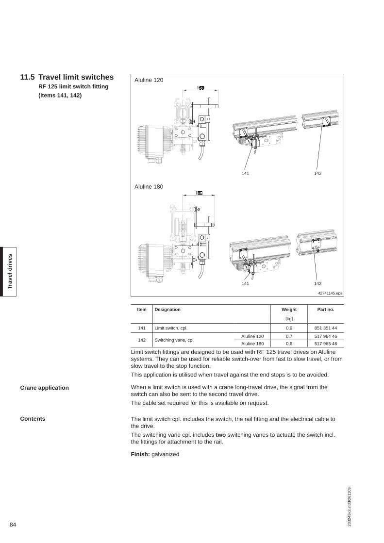
84 2032
45k3
.indd
/261
109
Trav
el d
rives
11.5 Travel limit switches RF 125 limit switch fi tting (Items 141, 142)
Item Designation Weight Part no.
[kg]
141 Limit switch, cpl. 0,9 851 351 44
142 Switching vane, cpl.Aluline 120 0,7 517 964 46Aluline 180 0,6 517 965 46
Limit switch fi ttings are designed to be used with RF 125 travel drives on Aluline systems. They can be used for reliable switch-over from fast to slow travel, or from slow travel to the stop function.This application is utilised when travel against the end stops is to be avoided.
When a limit switch is used with a crane long-travel drive, the signal from the switch can also be sent to the second travel drive.The cable set required for this is available on request.
The limit switch cpl. includes the switch, the rail fi tting and the electrical cable to the drive.The switching vane cpl. includes two switching vanes to actuate the switch incl. the fi ttings for attachment to the rail.
Finish: galvanized
Crane application
42741145.eps
141 142
Contents
Aluline 120
141 142
Aluline 180

852032
45k3
.indd
/261
109
RF
trav
el u
nits
12 Trolleys for travel drives
RF and DRF trolley (item 69)DRF 200 friction wheel travel drive (item 70)165 trolley coupling (item 71)
The trolleys shown are suitable for the following drives:Trolley for Aluline 120: RF 100, RF 125Trolley for Aluline 180: RF 100, RF 125, DRF 200
Finish: black (RAL 9005)
Item Designation Aluline 120 Aluline 180
Weight Part no. Weight Part no.
[kg] [kg]
69130 trolley 3,0 855 065 44 4,0 855 095 44270 trolley 3,5 855 066 44 4,3 855 096 44
71 165 trolley coupling 0,3 855 142 44
Aluline 180 with DRF 200 Aluline 120 with RF 125
42626447.eps

86 2032
45k4
.indd
/261
109
Link
bar
s
13 Link and spacer bars
13.1 Single-trolley link (Item 61)
Single-trolley links, hinged blocks, link bars or spacer bars can be used to connect trolleys and travel drives for any trolley combinations.The travel drive must always be connected to the load trolley.
The link provides an additional means for connecting spacer bars, buffers and travel drives to trolleys with a suspended load.
Finish: black (RAL 9005), steel
42606545.eps
Single-trolley link
Aluline 120 Aluline 180
42606946.eps
165 trolley coupling
Aluline 180 Aluline 120/180
Link bar, long
165 trolley couplings are used to connect friction wheel units in Aluline 180 crab frames.Long link bars can be used for any trolley combinations and special applications.
Finish: black (RAL 9005), steel
13.2 165 trolley coupling/long link bar
(Item 71)
Item Designation Aluline 120 Aluline 180
Weight Part no. Weight Part no.
[kg] [kg]
61 Single-trolley link 0,7 855 070 44 0,8 982 505 44
Item Designation Aluline 120 Aluline 180
Weight Part no. Weight Part no.
[kg] [kg]
71165 trolley coupling 0,3 855 142 44
Link bar, long 0,9 982 345 44 0,9 982 345 44

872032
45k4
.indd
/261
109
Link
bar
s
42606948.epsAluline 120
RF ergo hinged block13.3 RF ergo hinged block/link bar
(Item 71e)
Item Designation Section Weight Part no.
[kg]
71eRF ergo hinged block Aluline 120 0,38 855 125 44RF ergo link bar Aluline 180 0,84 851 120 44
Hinged blocks and link bars are used to connect tractor trolleys to ergo crab frames and ergo crane end carriages.
RF ergo link bar
Aluline 180

88 2032
45k4
.indd
/261
109
Link
bar
s
Hinged end piece
42626747.eps
RF hinged block Spacer bar for hinged blocks
72
77
13.4 Articulated spacer bar (Items 72, 73)
Spacer bars are used to distribute loads safely by separating several monorail hoist trolleys running on the same track. The spacer bar length is determined ac-cording to the information given in sections 3.3-3.5. The dead weight of the spacer bar must be included in load K when selecting the monorail. RF travel drives must always be connected to the load trolley.
Finish: Metal parts black (RAL 9005); pins, nuts and bolts galvanised
Example for ordering:2 off hinged block, part no. 982 402 441 off spacer bar for hinged blocks, A = 700 mm, part no. 850 337 44
Item Designation Fitted to Dimensions Weight Part no.
A min. A max. [kg]
72Hinged end piece Single-trolley link - - 0,75 982 402 44RF hinged block Trolley for RF/DRF - - 0,64 982 399 44
73 Spacer bar for hinged blocks Hinged end piece 70 2500 5.0/m 850 337 44
Examples
42608146.eps

892032
45k4
.indd
/261
109
Link
bar
s
13.5 Spacer bar for straight track, Aluline 180
(Item 76)
Spacer bars are used to distribute loads safely by separating several monorail hoist trolleys and single or double-girder cranes running on the same track.The dead weight of the spacer bar must be included in load K when selecting the monorail.
Finish: Metal parts black (RAL 9005); pins, nuts and bolts galvanised
Examples for ordering:2 off spacer bar with one open end, A = 3000 mm2 off spacer bar with two open ends, A = 2800 mm
Item Designation Fitted to Dimensions Weight Part no.
A min. A max. [kg]
76Spacer bar with one open end Spacer bar, trolley 350 3500 4,8 / m + 0.5 Standard drawingSpacer bar with two open ends Single trolley, load bar 650 3500 4,8 / m + 1,0 Standard drawing
42608147.eps
Spacer bar with one open end Spacer bar with two open ends
Examples with two open ends
42608148.eps

90 2032
45k4
.indd
/261
109
Buf
fers
Rubber end stop (item 98)Buffer fi tting (foamed plastic) (item 98)Buffer plate (item 98)RF buffer fi tting (foamed plastic) (item 98)RF buffer plate (item 98)
42608246.eps
Rubber end stop Single trolley (Aluline 180)
Item Designation Fitted to Weight Part no.
[kg]
98
Rubber end stopSingle-trolley link, load bar, spacer bar with two open ends, spacer bar with one
open end
0,44 982 395 44Buffer fi tting (foamed plastic) 0,80 982 378 44Buffer plate 0,49 982 377 44RF buffer fi tting (foamed plastic) RF 100, RF 125 and DRF 200 trolley 0,45 982 375 44
RF buffer plate 0,17 982 374 44
14 Buffers and end stops
Single trolley (Aluline 120)
Double trolley (Aluline 180)Double trolley (Aluline 120)Buffer fi tting (foamed plastic)
Buffer plate
RF buffer fi tting (foamed plastic)
RF buffer plate
Trolley for DRF 200Trolley for RF 125
Possible combinations
Single trolley Double trolleyAluline 120 Aluline 180 Aluline 120 Aluline 180
Buf
fer p
late
Rub
ber
Cel
lula
r foa
m
Buf
fer p
late
Rub
ber
Cel
lula
r foa
m
Buf
fer p
late
Rub
ber
Cel
lula
r foa
m
Buf
fer p
late
Rub
ber
Cel
lula
r foa
m
Buffer plate x x x x x x
Rubber end stop x x x x
Buffer fi tting (foamed plastic) x x x x x x x x
RF buffer fi tting or RF buffer plate
Components Examples

912032
45k4
.indd
/261
109
Buf
fers
In KBK Aluline installations, limit stops with rubber buffers, end caps with rubber buffers, cellular foam buffers or shock absorbers are used to limit long and cross-travel motions.In order to lessen the impact forces of several monorail hoists or cranes on the same track and/or to reduce the noise of impact, buffers should be provided be-tween the trolleys or cranes.For push travel hoist trolleys and cranes, rubber buffers are used for normal op-erating conditions, and foamed plastic buffers for a high degree of impact absorb-ency (buffer against buffer plate).Electrically or pneumatically driven hoists and cranes are fi tted with foamed plastic buffers (plastic buffer against buffer plate). Where travel speeds exceed 21 m/min, the ends facing each other must be fi tted with identical buffers (foamed plastic buffer against foamed plastic buffer).
Finish: black (RAL 9005), metallic parts of steel

92 2032
45k4
.indd
/261
109
Fitti
ngs
42610145.eps
Mounting bracket/screw set15.2 Mounting bracket/screw set
(Item 89)
The mounting bracket is used together with the screw set as a means of universal fastening for various fi ttings. However, it must not be used as a load bearing sus-pension element.
Finish: galvanized
15.1 Trolley attachment bracket with pin
(Item 53)
42610245.eps
Aluline 120 Aluline 180
Trolley attachment brackets with pins make it possible to attach towing arms, cur-rent collectors, switches, small terminal boxes, counterweights and similar parts.Offset fi ttings must be balanced by counterweights or by loading the trolley to pre-vent it from tilting.
Finish: black (RAL 9005)
Trolley attachment bracket with pin
15 Fittings
3 thick
Item Designation Weight Part no.
[kg]
89Attachment bracket 0,07 712 275 47
M8 x 20 screw set 0,02 712 325 47
Item Designation Aluline 120 Aluline 180
Weight Part no. Weight Part no.
[kg] [kg]
53 Trolley attachment bracket with pin 0,48 980 041 44 0,66 982 041 44

932032
45k4
.indd
/261
109
Fitti
ngs
15.3 Mounting plates15.3.1 Mounting plate 1 for switch
and magnet fi ttings (Item 95)
42641344.eps
Item Dimensions [mm]1 Dia. 06,52 Dia. 09,03 Dia. 26,04 R 04,05 Dia. 05,5 x 326 Dia. 06,5 x 707 Dia. 06,5 x 408 Dia. 09,0 x 309 Dia. 09,0 x 32
2 thick
Finish: galvanized
Item Designation Weight Part no.
[kg]
95 Mounting plate 1 0,26 505 753 44
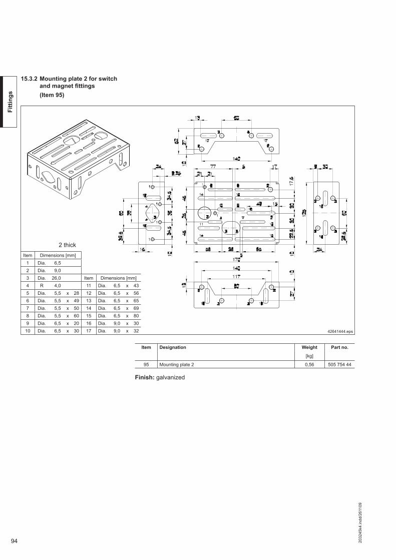
94 2032
45k4
.indd
/261
109
Fitti
ngs
15.3.2 Mounting plate 2 for switch and magnet fi ttings
(Item 95)
42641444.eps
Item Dimensions [mm]1 Dia. 06,52 Dia. 09,03 Dia. 26,0 Item Dimensions [mm]4 R 04,0 11 Dia. 06,5 x 435 Dia. 05,5 x 28 12 Dia. 06,5 x 566 Dia. 05,5 x 49 13 Dia. 06,5 x 657 Dia. 05,5 x 50 14 Dia. 06,5 x 698 Dia. 05,5 x 60 15 Dia. 06,5 x 809 Dia. 06,5 x 20 16 Dia. 09,0 x 30
10 Dia. 06,5 x 30 17 Dia. 09,0 x 32
2 thick
Finish: galvanized
Item Designation Weight Part no.
[kg]
95 Mounting plate 2 0,56 505 754 44

952032
45k4
.indd
/261
109
Fitti
ngs
15.3.3 Mounting plate 3 U-plate (Item 95)
42673344.eps4 thick
15.3.4 Mounting plate 4 L-plate (Item 95)
42673444.eps4 thick
Item Dimensions [mm]1 Dia. 06,32 Dia. 11,03 Dia. 13,04 R 13,05 R 16,06 Dia. 09,0 x 147 Dia. 09,0 x 18
Item Dimensions [mm]1 Dia. 06,5 x 66,52 Dia. 06,5 x 95,53 Dia. 06,5 x 25,54 Dia. 08,5 x 18,5
Item Designation Weight Part no.
[kg]
95 Mounting plate 3 1,1 385 554 46
Finish: galvanized
Item Designation Weight Part no.
[kg]
95 Mounting plate 4 0,38 622 533 46
Finish:: galvanized

96 2032
45k4
.indd
/261
109
Pow
er s
uppl
y
16.1 Electrical power supply
16.1.1 Trailing cable, General information
A cable (4 x 1,5) running on cable sliders and larger or several cables running on cable trolleys in the Aluline section is the most economical power supply system.Alternative: Cable trolleys running in KBK 0 rail, fi tted to the side of the Aluline sec-tion.
16 Power supply to crabs and cranes
Runways Cable sliders are used for one cable on tracks with simple electrical power sup-plies to the trolley or to the crane.Cable trolleys should be used for longer tracks, electric long and cross-travel drives and when fl at cables with outside dimensions greater than 8 mm x 19 mm or when several fl at cables are used.
The required cable length is calculated as follows:
Track and crane girder length (m) x 1,2 + length of feeder (m)
The number of sliders or cable trolleys required for a crane or track is calculated taking into consideration cable sag and track or crane girder length.Max. trailing cable length with cable sliders: 30 mMax. trailing cable length with cable trolleys: 50 mRequired number of sliders or trolleys n:
Cable length
Number of sliders or cable trolleys
Two trolleys or cranes on one track
Approach dimension
More than two trolleys or cranes on one track
The approach dimension of the crane or travelling hoist is increased by the dis-tance required for close accumulation of cable sliders and cable trolleys. An inter-nal buffer stop should be fi tted to protect the accumulated sliders or trolleys.For KBK Aluline installations with KBK 0 fi tted on the side, the approach dimen-sion can be reduced by arranging the cable trolley accumulating section next to the crane or travelling hoist, or by extending the KBK 0 rail beyond the end of the track.
If two hoists operate on one monorail track or two cranes on one runway, power supply via one fl at cable for each of them from opposite monorail or runway ends may be provided.See technical data sheet 202 617 44 for details (KBK 0, KBK 25; KBK 100 trailing cable power supply).
Power supply by fl at cable is not possible if more than two travelling hoists or two cranes operate on one runway. In these cases, power must be supplied via a con-ductor line.
n =Track or crane girder length [m]
- 1Cable sag [m] x 2
42610444.eps
Trailing cable with cable slider Trailing cable with cable trolley KBK 0 trailing cable power supply

972032
45k4
.indd
/261
109
Pow
er s
uppl
y
External KBK 0 trailing cable power supply
42609944.eps
KBK 0 trailing cable power supply
Aluline 120 Aluline 180
A trailing cable power supply system arranged at the side of the Aluline rail can reduce the approach dimension and the section required to accumulate the cable trolleys can extend beyond the end of the track.See technical data sheet 202 617 44 for details.
42610044.eps
Demag Compact Line DCL conductor line
Aluline 120 Aluline 180
A conductor line is arranged at the side of the Aluline rail if more than two travelling hoists or two crane girders run on one track. Conductor lines offer good protection against moisture and mechanical damage.Type of enclosure: IP 23; permissible voltage: 500 V; temperature range: 0 °C to +70 °C.Details see:Technical data sheet 203 387 44 (Demag Compact Line DCL),Technical data sheet 203 510 44 (DCL on KBK).
16.1.2 External DCL Demag Compact Line
Items required for fi tting to Aluline rails
1) See technical data sheet 203 510 44
Item Fitting KBK 0 and DCL to Aluline 120 / Aluline 180 Weight Part no.
[kg]
(1) C rail fi tting 600 1,6 855 099 44
(2)DCL engaging arm for current collector Standard drawing 1)
Engaging arm attachment for KBK 0/120 towing trolley 0,9 855 104 44Engaging arm attachment for KBK 0/180 towing trolley 1,1 855 105 44
(3) C-rail counterweight fi tting Standard drawing 1)
1 23 1 23

98 2032
45k4
.indd
/261
109
Pow
er s
uppl
y
40
60
125
max
. 23
max. 50
110
max. 50
max
. 23
105
max
. 23
max. 50max. 50
max
. 23
70
Rail end cable clamp (item 83)Flat cable with PE (item 84)Cable slider (item 85)Cable trolley (item 86)
42608344.eps
Rail end cable clamp, fl at cable, cable slider, cable trolley
Aluline 120
Cable slider Cable trolleys Rail end cable clamp
Aluline 180
Cable sliderCable trolleys
Rail end cable clamp
Rail end cable clamps are bolted to Aluline 120 or Aluline 180 end caps. This pro-vides strain relief of the fl at cable to the terminal box and a favourable fi xing point for the cable between the crane girder and track.The plastic-sheathed fl at cable (cold-resistant) may be used in buildings with a dry or humid atmosphere, or in the open. Flat cable is fl exible in one plane.Cable sliders with a cable locking screw are suitable for one fl at cable with maxi-mum overall dimensions of 19 mm x 8 mm. They are made of temperature-resist-ant plastic.Cable trolleys can be used to support cables, compressed air or water hoses. Ad-ditional holes can be drilled for fi xing stress-relief strainers.Temperature range for fl at cable, slider and cable trolley: 0 °C to +50 °C.Finish: Rail end cable clamp: galvanized Cable slider plain plastic Clamping plate: Black plastic Cable trolley 120: Black plastic Cable trolley 180: galvanized
Item Designation No. of conductors x rated cross-
section
External dimen-
sion
Aluline 120 Aluline 180
Weight Part no. Weight Part no.
[mm2] [mm] [kg] [kg]
83 Rail end cable clamp 0,10 982 114 44 0,20 855 090 44
84 Flat cable with PE
4 x 1.5 19 x 8 0.21/m 471 352 44 0.21/m 471 352 444 x 2.5 21 x 8 0.26/m 504 208 44 0.26/m 504 208 448 x 1.5 33 x 8 0,35/m 504 226 44 0,35/m 504 226 44
85 Cable slider only for fl at cable4 x 1.5
0,02 855 143 44 0,04 982 325 4486 Cable trolleys 0,22 982 470 44 0,50 855 085 44
16.1.3 Trailing cable, components and attachments

992032
45k4
.indd
/261
109
Pow
er s
uppl
y
Crab frame cable clamps are suspended from the frames of push travel crab frame hoists to relieve the pull on the terminals.
Crane bridge cable clamp (item 80)
42610545.eps
Crane bridge cable clamp
Aluline 120 Aluline 180
Crane bridge cable clamps are used for push travel single/double-girder cranes to prevent the fl at cable running from the crane runway to the crane girder from being subjected to side pull.
42610645.eps
Crab frame cable clampCrab frame cable clamp (item 81)
42610745.eps
RF trolley cable clampRF trolley cable clamp (item 82)
Aluline 120 Aluline 180
RF trolley cable clamps are fi tted to electric travel crab frame hoists/cranes to relieve the pull on the terminals.
Item Designation Aluline 120/180
Weight Part no.
[kg]
82 RF trolley cable clamp 0,6 982 578 44
Item Designation Aluline 120/180
Weight Part no.
[kg]
80 Crane bridge cable clamp 0,6 855 106 44
Item Designation Aluline 120/180
Weight Part no.
[kg]
81 Crab frame cable clamp 0,1 982 577 44

100 2032
45k4
.indd
/261
109
Pow
er s
uppl
y
16.1.4 Mains connection switch/isolating switch
(Item 88)
Switch-isolators are suitable for use as mains connection or isolating switches.Mains connection switch: Stationary switch-isolator for a crane installation with
one or more cranes/travelling hoistsIsolator: On-board switch-isolator on cranes or travelling hoists on a common power supply line (conductor line).Switch-isolators can be locked in the OFF (0) position against unauthorised resto-ration of the power supply by up to three padlocks.Two M20 x 1,5 cable entries are available. Type of enclosure IP 55.DT 16a switch-isolator without fuses;DT 25a switch-isolator without fuses;DT 25a-S switch-isolator with fuse base for 3 fuses.
42609747.eps
Nominal current D fuse link, delayed action D screw-in adapter for fuse insert
[A] Part no. Part no.6 451 663 99 504 905 44
10 451 643 44 504 906 4416 451 644 44 504 907 4420 451 645 44 504 908 4425 451 646 44 504 909 44
DT 25a
Item Designation Voltage Current Weight Part no.
[V] [A] [kg]
88 Switch-isolatorDT 16a ≤ 500 max. 20 0,32 575 479 44DT 25a
≤ 690 max. 250,40 575 480 44
DT 25a-S 1,60 473 037 44
Fuse links and inserts for DT 25a-S
DT 25a-SDT 16a

1012032
45k4
.indd
/261
109
Pow
er s
uppl
y
A terminal box must be provided as the junction with the fi xed round-section cable when fl at cables are used to supply power to KBK Aluline installations.
Finish: Aluminium enclosure with 6 modular spring-loaded terminals (grey) up to (2,5 mm2) fi tted on mounting rail, RAL 7035 (light grey)
1) Nut
for fl at cables Terminal box Twist-type cable entry gland for
Round cable Flat cable
Weight Part no. Size Part no. Part no.
[kg]
4 x 1.5 mm2 0,34 504 650 44 M20 x 1,5 794 947 44 794 923 44
4 x 2,5 mm2 0,60 575 351 44 M25(M16, M32)
794 946 44794 905 44 1)
794 927 44794 905 44 1)
16.1.5 Terminal box (Item 94)
42639844.eps
Item Designation Weight Part no.
[kg]
94 Terminal box 0,4 504 650 44

102 2032
45k4
.indd
/261
109
Pow
er s
uppl
y
16.1.6 Mounting brackets for switches and terminal boxes
Mounting bracket for enclosure on RF 125(Item 92)
42683445.eps
The mounting bracket is used to attach the enclosure, part no. 575 381 44.
Finish: black
Enclosure, part no.: 575 381 44
Item Designation Weight Part no.
[kg]
92 Mounting bracket for terminal box 0,17 855 150 44
42641244.eps
Finish: galvanized
Aluline 120 Aluline 180
Terminal box504 650 44
Mounting bracket for terminal box(Item 92)
Item Designation Weight Part no.
[kg]
92 RF 125 enclosure mounting bracket 0,6 851 270 44

1032032
45k4
.indd
/261
109
42642345.eps
Small DRF attachment bracket Large DRF attachment bracket
Finish: galvanized
Item Designation Weight Part no.[kg]
93Small mounting bracket 0,9 851 222 44Large mounting bracket 3,9 851 220 44
Example: fi tted to DRF
Item Designation Part no.
aMains connection/isolating switch
DT 16 a 575 479 44
bDT 25 a 575 480 44DT 25 a-S 473 037 44
cTerminal box
180 x 130 x 75 575 351 44d 255 x 180 x 75 575 352 44
eHousing
232 x 212 x 137575 381 44
Crane bridge enclosure 772 078 45
fHousing
400 x 300 x 155575 382 44
Crane bridge enclosure 2 772 178 45
g Receiver DRC-MP 773 432 44
h Terminal box, E box 185 x 163 x 102
Universal E box 772 167 45
Terminal box3T3 772 174 45Manual crab 772 175 45DC / diode 772 165 45
Polu box 772 280 45
Signal converter3TK 772 176 45KT3 772 177 45DT3 772 166 45
42683545.eps
Small mounting bracketfor a, b, c, e, g, h
Large mounting bracketfor a, b, d, f
a or b e a or b f
Pow
er s
uppl
y
Attachment bracket(Item 93)

104 2032
45k4
.indd
/261
109
Pow
er s
uppl
y
Bracket for isolator switch(Item 90)
42610148.eps
The bracket for isolator switches is used to accommodate isolator switches and terminal boxes. See small mounting bracket for possible connections.
Finish: galvanized
Aluline 120
DT 25a-S
Aluline 120/180
Item Designation Weight Part no.
[kg]
90 Bracket for isolator switch 0,7 855 152 44
Switch and terminal box mounting brackets(Item 90)
42609848.eps
Switch and terminal box mounting brackets on push travel monorail hoists
Switch brackets are required when several push travel monorail trolleys are used with a common power supply on one track.A mounting bracket consists of a bracket, eye with nut for suspension, and fasten-ing material for the enclosure/switch. It may be necessary to drill additional holes for the enclosure when it is fi tted to the mounting bracket. See small mounting bracket for possible connections.
Item Designation Weight Part no.
[kg]
90 Switch bracket 0,75 851 223 44

1052032
45k4
.indd
/261
109
Pow
er s
uppl
y
16.2 Pneumatic power supply
16.2.1 General information
Special power supply lines are required for pneumatic load lifting modules such as Demag D-BP rope balancers.In some applications electric power is required in addition to pneumatic energy (e.g. for manual force control of the Demag rope balancer).
The supply lines are laid in a protective hose and attached to special points of the crane runway and to the crane girder as well as to cable trolleys. The helical pro-tective hose is always right-handed and has a sag of approx. 500 mm.
Length of the protective hose = Travel path [m] x 1,3 + connecting length on both sides [m]
Number of cable trolleys = Length of travel path (rounded off to full metres) -1
Length of cable accumulating section = Number of cable trolleys + reserve x length of cable trolley
Example:KBK Aluline 120 (classic) single-girder crane
42639944.eps
Separation of power supply: Transfer point→ crane bridge/crane track (Detail X)Power supply interface: End of crane track (Detail Y)
Cable trolleysFixed point Fixed point
Right-handed protective hose
42640044.eps
100
Detail Y
108
103
101
84
102
107
88
106b
Y
Detail X
X
106a105 59
109
104 106c
92b
92a
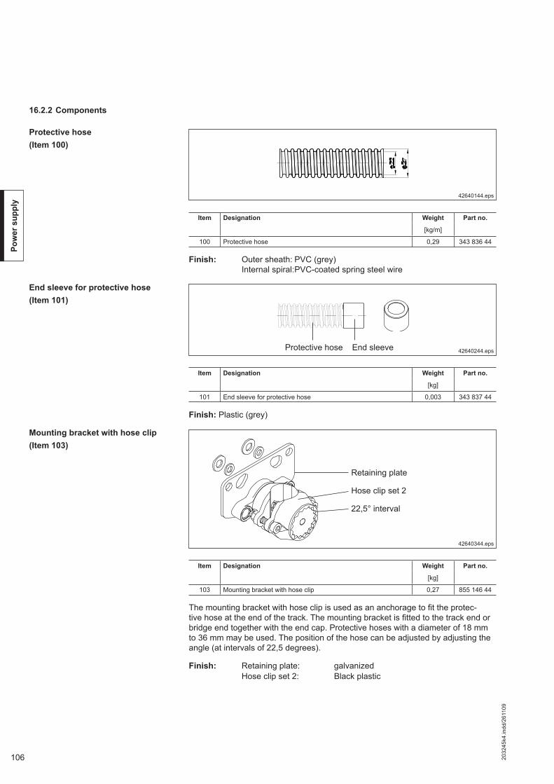
106 2032
45k4
.indd
/261
109
Pow
er s
uppl
y
16.2.2 Components
42640144.eps
The mounting bracket with hose clip is used as an anchorage to fi t the protec-tive hose at the end of the track. The mounting bracket is fi tted to the track end or bridge end together with the end cap. Protective hoses with a diameter of 18 mm to 36 mm may be used. The position of the hose can be adjusted by adjusting the angle (at intervals of 22,5 degrees).
Finish: Retaining plate: galvanized Hose clip set 2: Black plastic
Finish: Outer sheath: PVC (grey) Internal spiral: PVC-coated spring steel wire
42640244.epsProtective hose End sleeve
Mounting bracket with hose clip(Item 103)
42640344.eps
Retaining plate
Hose clip set 2
22,5° interval
Protective hose(Item 100)
Item Designation Weight Part no.
[kg/m]
100 Protective hose 0,29 343 836 44
End sleeve for protective hose(Item 101)
Finish: Plastic (grey)
Item Designation Weight Part no.
[kg]
101 End sleeve for protective hose 0,003 343 837 44
Item Designation Weight Part no.
[kg]
103 Mounting bracket with hose clip 0,27 855 146 44

1072032
45k4
.indd
/261
109
Pow
er s
uppl
y
Cable trolley with hose clip(Item 104)
42640444.eps
Cable trolleys are suitable for protective hoses with an external diameter of 18 mm to 36 mm. The retaining plate and clamping section on cable trolleys are pre-as-sembled at an angle of 45° to the direction of travel. Adjustment of the angle is possible at intervals of 22,5°. The hose is fi tted by bolting the clamp section with the hose clip from below.
Temperature range: -20°C to + 70°C
Finish: Trolley: plastic, black (Aluline 180): galvanized Axle with ball bearings: Steel Travel rollers: plain plastic Hose clip: Black plastic
Aluline 120Load: max. 25 kg
Aluline 180Load: max. 40 kg
Clamp section Hose clip
Retaining plate
Item Designation Size Weight Part no.
[kg]
104 Cable trolley with hose clipAluline 120 0,37 855 148 44Aluline 180 0,65 855 149 44

108 2032
45k4
.indd
/261
109
Pow
er s
uppl
y
If power is supplied via hoses, the components listed can be used to fi t the hose to retaining plates and walls as well as to KBK cable trolleys.If retaining plates are used, adjustment is possible at intervals of 22,5°.
Finish: Black plastic
Hose clip set(Item 105)
42640544.eps
22,5° interval
Retaining plate
Clamp section
Hose clip
Hose clip set 1
18 to 36 clamping range 18 to 36 clamping range
Hose clip set 2
22,5° interval
Retaining plate
Clamp section
Clamp section
Dimension for hose27 dia. 36 dia.
Dimension for hose27 dia. 36 dia.
Item Designation Weight Part no.
[kg]
105Hose clip set 1 0,16 855 135 44Hose clip set 2 0,14 855 145 44

1092032
45k4
.indd
/261
109
Pow
er s
uppl
y
Bracket for fi xed point AL(Item 109)
The bracket is used for transfer between a crane bridge and crane track and is fi t-ted in the lateral grooves of the crane bridge by means of a screw set. The position of the hose can be changed by adjusting the angle (at 22,5° intervals) of hose clip set 2.Protective hoses with a diameter of 18 mm to 36 mm may be used.Finish: Fixed point plate: Galvanised steel Hose clip set 2: Black plastic
42641044.eps
Aluline 180Aluline 120
Screw setAnchorage plateHose clip set 222,5° interval
Item Designation Weight Part no.
[kg]
109 Bracket for fi xed point AL 0,28 855 147 44

110 2032
45k4
.indd
/261
109
Pow
er s
uppl
y
Bulkhead gland(Item 106b)
42640944.eps
Two hose ends (nominal size 12) can be interconnected.
Finish: Black plastic
Angle connector(Item 106c)
42641144.eps
Item Designation Weight Part no.
[kg]
106b Bulkhead gland 0,09 343 786 44
Finish: Nickle-plated brass
Item Designation Weight Part no.
[kg]
106c Angle connector 0,05 343 835 44
Angular connection for balancer(Item 106a)
42640645.eps1) Only for manual force control of the balancer, included in the scope of delivery.
1)
Item Designation Weight Part no.
[kg]
106aAngular connection for balancer 3/8“ 0,06 343 777 44Angular connection for balancer 1/2“ 0,06 343 778 44
Finish: Nickle-plated brass

1112032
45k4
.indd
/261
109
Pow
er s
uppl
y
Angle for bulkhead gland(Item 108)
42640844.eps
Item Designation Weight Part no.
[kg]
108 Angle for bulkhead gland 0,03 984 696 44
Attached with screw set (item 89)
Finish: galvanized
Item Designation Design Weight Part no.[kg]
59 Load bar for rope balancerD-BP 55/110 RAL 9005 (black) 1,85 984 685 44
84
highly fl exible round cable 3G1,5 mm² Outside dia. 7,9 mm 0,09 [kg/m] 343 838 44
highly fl exible round cable 5G1,5 mm² Outside dia. 9,6 mm 0,14 [kg/m] 343 839 44
88 DT 16a mains connection switch 0,32 895 167 4489 M8x20 screw set galvanized 0,02 712 325 47
102 Plastic hose, silver in colour Outside dia. 12 mmInside dia. 8 mm 0,08 [kg/m] 343 840 44
Other components for pneumatic power supply
Maintenance unit(Item 107)
42640744.eps
Input pressure: 0 to max. 16 barPressure regulating range: 0,5-10 barFilter element: 5 μmCondensed water drainage: manualInput: Sleeve suitable for hose with 13 mm internal diameterOutput: Angular connection for plastic hose with 12 mm exter-
nal diameter
Item Designation Weight Part no.
[kg]
107 Maintenance unit 1,35 851 199 44

112 2032
45k4
.indd
/261
109
Stan
dard
ele
c. e
quip
.
KBK installations with DK chain hoists may be controlled either by direct on-line control or through contactors, KBK installations with DC chain hoists are always controlled through contactors.direct controlDirect on-line control is recommended as standard in cases where no special operating conditions require contactor control, and where drive motors can be controlled with the operating voltage directly through specially developed Demag DSK/DST control pendants.contactor controlSpecial Demag DSC/DSK/DSE control pendants are used for controlling all drive motors through contactors. The control circuits connected to earth on one side with control transformers. DC chain hoists have 24 V control voltage, DK hoists are preferably operated with 230 V control voltage. Special measures may be required for applications in plants with a corrosive atmosphere or relatively high humidity in order to increase the type of enclosure or to protect the components. A control volt-age of 42 V is recommended in such environments.ConversionSubsequent conversion from direct to contactor control is possible. Conversion to wireless control systems, IR or radio remote, is possible in connection with contac-tor control.Electro-magnetic compatibility (EMC)KBK installations comply in full with the provisions of the EC-EMC regulations, as laid down in the EN 61000-6-4 and EN 61000-6-2 harmonised standards.Special protectionSpecial safety measures are available for KBK installations used at locations and in rooms requiring measures exceeding normal standards.Such measures may be required in:• Explosion hazard atmospheres• Pickling plants• Galvanising facilities• Outdoors
All Demag components and assemblies fully comply with DIN VDE regulations, relevant accident prevention regulations and relevant standards. All relevant na-tional or local regulations must be taken into account when planning electrical installations. We refer particularly to DIN VDE 0100 and the harmonised European standards.UL and CSA-tested components available on application.
1. It must be possible to cut off all phases of the main power supply line by means of one mains switch. This switch must be protected against unauthorized resto-ration of the power supply.
2. An isolator which can be padlocked should be provided for each hoist if several of these, operating on one track, are fed through one and the same power sup-ply line.
3. Each hoist must be fi tted with an emergency-stop device which brings the mo-tive drives to a standstill and interrupts the power supply to these drives.
4. A crane switch is required for - electrically powered cranes, - cross-travel drives with an output great-
er than 500 W, - wireless control systems.5. Installation of a protective earth conductor, marked green/yellow over its entire
length, is obligatory. It must be impossible for earth conductor current collectors to be exchanged for phase collectors.
17 KBK standard electrical equipment
17.1 General
Regulations
Important requirements from the standards

1132032
45k4
.indd
/261
109
Stan
dard
ele
c. e
quip
.
Power supply The required power supply system should be selected and separately ordered in accordance with the KBK standard electrical equipment table. When specifying the power supply line, the total length of the supply lines along the crane runway and crane bridge must be added and checked to ensure that it is within the maximum permissible voltage drop according to section 17.4.

114 2032
45k4
.indd
/261
109
Stan
dard
ele
c. e
quip
.
KBK item with
Required cable(s) onthe crane bridge the crab
Con
trol
Con
trol
pen
dant
Trav
el m
otio
n
Pow
er s
uppl
y on
the
cran
e br
idge
Lifti
ng /
low
erin
g2
spee
ds
Cro
ss tr
avel
2 sp
eeds
Long
trav
el2
spee
ds
DC
-Pro
1-1
0D
C-C
om 1
-10
Show
ing
EB, E
HK
, ZH
Kse
e se
ctio
n 17
.3
4 x
1,5 fl a
t cab
lePa
rt n
o. 4
71 3
52 4
4
13 x
1,5
fl at
cab
lePa
rt n
o. 8
95 1
71 4
4
12 x
1,5
roun
d ca
ble
Part
no.
504
945
44
Mai
ns c
able
DC
→ E
22Pa
rt n
o. 7
20 0
72 4
5
Con
trol
cab
le D
C →
E22
Part
no.
720
070
45
Req
uire
d nu
mbe
r of p
oles
on
the
cran
e br
idge
(PE
= pr
otec
tive
eart
h co
nduc
tor)
cont
acto
r con
trol
DSC manual
Trailing cable
O x 1 1 3+PE
DSE-C
electric O O x 2 1 1 1 3+PE
electric with crane switch contactor
O O E20 3 1 1 1 3+PEO O E28 7 1 1 8+PE
Conductor line O O E28L 1 8+PE
Trailing cable O O O E32 6 1 1 1 1 8+PE
Conductor line O O O E32L 1 1 1 8+PE
x = no KBK item required (see DC-Pro / DC-Com documents)
17.2 KBK standard electri-cal equipment with DC
Selection table for installations with 2-stage DC-Pro/DC-Com chain hoist and RF 125
KBK item with
Required cable(s) on the crane bridge the crab
Con
trol
Con
trol
pen
dant
Trav
el m
otio
n
Pow
er s
uppl
y on
the
cran
e br
idge
Lifti
ng /
low
erin
ginfi n
itely
var
iabl
e
Cro
ss tr
avel
infi n
itely
var
iabl
e
Long
trav
elinfi n
itely
var
iabl
e
DC
S-Pr
o 1-
10
Show
ing
EB, E
HK
, ZH
Kse
e se
ctio
n 17
.3
4 x
1,5 fl a
t cab
lePa
rt n
o. 4
71 3
52 4
4
13 x
1,5
fl at
cab
lePa
rt n
o. 8
95 1
71 4
4
12 x
1,5
roun
d ca
ble
Part
no.
504
945
44
Mai
ns c
able
DC
→ E
22Pa
rt n
o. 7
20 0
72 4
5
Con
trol
cab
le D
C →
E22
Part
no.
720
070
45
Req
uire
d nu
mbe
r of p
oles
on
the
cran
e br
idge
(PE
= pr
otec
tive
eart
h co
nduc
tor)
cont
acto
r con
trol
DSC-S manual
Trailing cable
O x 1 1 3+PE
DSE-10CS
electric O O x 2 1 1 1 3+PE
electric with crane switch contactor
O O E20 3 1 1 1 3+PEO O
1)
7 1 1 8+PE
Conductor line O O 1 8+PE
Trailing cable O O O 6 1 1 1 1 8+PE
Conductor line O O O 1 1 1 8+PE
x = no KBK item required (see DCS-Pro documents)
1) on request
Selection table for installations with DCS-Pro variable-speed chain hoist and RF 125

1152032
45k4
.indd
/261
109
Stan
dard
ele
c. e
quip
.
Contents Contents Designation Part no.
E20E32E32L
Crane bridge enclosure 772 078 45RF 125 enclosure mounting bracket 851 270 44
Circuit diagram
E28E28L
Manual travelling hoist terminal box 772 075 45Fibox enclosure DC mounting bracket 716 540 45Crane bridge enclosure 772 078 45RF 125 enclosure mounting bracket 851 270 44
Circuit diagram
The cables listed in the tables are not included in the electrical items and must therefore be ordered separately.Flat and round cables are supplied by the metre, whereas the cables for the travel-ling hoist are prepared in suitable lengths.
Technical data, installation diagrams and components for electric travel motions for KBK installations with DC chain hoists and conventional drives such as DRF 200, for example, on request.

116 2032
45k4
.indd
/261
109
Stan
dard
ele
c. e
quip
.
Sus
pens
ion
mon
orai
l
EB 1 EB 2 EB 3
40784341.eps 40474841.eps 40474844.eps
Sin
gle-
gird
er c
rane
EHK 1 EHK 2 EHK 3
40784342.eps 40474842.eps 40474845.eps
Sin
gle-
gird
er c
rane
, rig
id/d
oubl
e-gi
rder
cra
ne
ZHK 1 ZHK 2 ZHK 3
40784343.eps 40474843.eps 40474846.eps
ZHK 4 ZHK 5 ZHK 6
40784345.eps 40784346.eps 40784347.eps
ZHK 7
40784344.eps
88
17.3 Schematic illustrations of cable arrangements and cable clamps
Key to symbols Cable clamp Round cable (item 92), rigidly mounted on the crane bridge Flat cable (item 84), freely suspended Monorail hoist with cable entry on the hoist unit Double-rail hoist with cable entry on the hoist unit RF (friction wheel travel drive) Control element
Item Designation Section80 Crane bridge cable clamp 16.1.381 Crab frame cable clamp 16.1.382 RF trolley cable clamp 16.1.383 Rail end cable clamp 16.1.385 Cable slider 16.1.388 Mains connection switch 16.1.3

1172032
45k4
.indd
/261
109
Stan
dard
ele
c. e
quip
.

118 2032
45k4
.indd
/261
109
1) The lengths of the supply lines are calculated on the basis of an earth-loop impedance of 200 mΩ.
DCS-Pro, DCMS-Pro, DCRS-Pro chain hoist
Mains connection delay fuse links Size Motor size 380-415V 220-240V 500-525V 440-480V 220-240V 380-400V 575V
50Hz 60Hz[A] [A] [A] [A] [A] [A] [A]
DC-Com 1 ZNK 71 B 8/2
66
6 66 6
6DC-Com 2 ZNK 71 B 8/4DC-Com 5 ZNK 80 A 8/4
DC-Com 10ZNK 100 A 8/2 10 10 10ZNK 100 B 8/2 16 25 10 16 25 20 16
Supply cables 1) for 5% voltage drop ΔU and starting current IASize Motor size 380-415V 220-240V 500-525V 440-480V 220-240V 380-400V 575V
50Hz 60Hz[mm2] [m] [mm2] [m] [mm2] [m] [mm2] [m] [mm2] [m] [mm2] [m] [mm2] [m]
DC-Com 1 ZNK 71 B 8/2
1,5100 1,5
89
1,5100
1,5100 1,5
76
1,5100
1,5100
DC-Com 2 ZNK 71 B 8/4 100 100DC-Com 5 ZNK 80 A 8/4 67 56
DC-Com 10ZNK 100 A 8/2 34 29 80ZNK 100 B 8/2 38 2,5 21 61 43 2,5 18 26 59
DC-Com chain hoist
Supply cables 1) for 5% voltage drop ΔU and starting current IA
Size Motor size 380-480 V, 50/60 Hz, 3 ~[mm²] [m]
DCS-Pro 1DCS-Pro 2
DCMS-Pro 1DCMS-Pro 2DCRS-Pro 1DCRS-Pro 2
ZNK 71 B 41,5
100
DCS-Pro 5 ZNK 80 A 4DCS-Pro 10 ZNK 100 A 4 40
Mains connection delay fuse links Size Motor size 380 – 480 V, 50/60 Hz, 3 ~
[A]DCS-Pro 1DCS-Pro 2
DCMS-Pro 1DCMS-Pro 2DCRS-Pro 1DCRS-Pro 2
ZNK 71 B 46
DCS-Pro 5 ZNK 80 A 4DCS-Pro 10 ZNK 100 A 4 10
Mains connection delay fuse links Size Motor size 380-415V 220-240V 500-525V 440-480V 220-240V 380-400V 575V
50Hz 60Hz[A] [A] [A] [A] [A] [A] [A]
DC-Pro 1ZNK 71 A 8/2
66
66 6 6
6ZNK 71 B 8/2
DC-Pro 2DC-Pro 5 ZNK 80 B 8/2
1010 15
10DC-Pro 10
ZNK 100 A 8/2 6 10
ZNK 100 B 8/2 16- 16
15- 20 15
DC-Pro 1620 10 25 15 10
ZNK 100 C 8/2 20 - 16 20 - 25 15DC-Pro 25
Supply cables 1) for 5% voltage drop ΔU and starting current IASize Motor size 380-415V 220-240V 500-525V 440-480V 220-240V 380-400V 575V
50Hz 60Hz[mm2] [m] [mm2] [m] [mm2] [m] [mm2] [m] [mm2] [m] [mm2] [m] [mm2] [m]
DC-Pro 1ZNK 71 A 8/2
1,5
1001,5
89
1,5
1001,5
100 1,576
1,5100
1,5
100ZNK 71 B 8/2
DC-Pro 2DC-Pro 5 ZNK 80 B 8/2
9431 26 75
DC-Pro 10ZNK 100 A 8/2 34 29 78
ZNK 100 B 8/238 - - 61 43 - - 2,5 45 78
DC-Pro 1646 2,5 25 73 52 2,5 21 1,5
3690
ZNK 100 C 8/2 2,5 47 - 45 2,5 53 - 2,5 51DC-Pro 25
17.4 Electrical key values for DC-Pro, DC-Com, DCS-Pro, DCMS-Pro, DCRS-Pro
DC-Pro chain hoist

1192032
45k4
.indd
/261
109
Project engineering sheet for KBK installations
Please enclose a sketch. Please send to your nearest Demag Cranes & Components sales offi ce or direct to Demag Cranes & Components GmbH.
Customer Project no.Customer no.CustomerProcessed by Date
Dept.:/Sales offi ce
Stage of customer‘s planning Scope of required quotationFinancial planning for investments Budget offer negotiated on _______________
Tech. Prelim. Detailed planning None Incl. sketch with ___________________
Implementation expected ________________ Load information Customer visit
Invitation to tender Detailed quotation Telephone contact
Order soon to be placed with steelwork with erection
Quotation deadline _____________________ Delivery deadline _____________________Type of installation
Suspension monorail Double-rail track KBK track section __________
Single-girder crane with latching device KBK crane section __________ KBK track section __________
Double-girder crane More than 2 crane tracks KBK crane section __________ KBK track section __________
Technical dataSWL _________________ kg Average operating time _______________________ hours/dayTrack length _________________ mCrane length _________________ m Crane span dimension _______________________ mNumber of trolleys on one track _________________ Load hook distance for several loads _______________________ mmNumber of cranes on one runway _________________ Highest hook position above fl oor _______________________ mInstallation site ____________________________________________________________________________________________________Type of supporting structure / suspension methods / fl ange ________________________________________________________________________Clear height from fl oor to bottom edge of supporting structure ________________________________________________________________________Hoist unitElectric chain hoist type _______________________ Hoist speed v ______________ / ______________ m/minHook path _______________________ mTravel speedsCross travel manual electric, v = ______________ / ______________ m/min
Crane manual electric, v = ______________ / ______________ m/min
Power supplyOn crane Trailing cable Cable sliders Cable trolleys KBK II-R4 KBK II-R5
DKK DEL Continuous In sections
On track Trailing cable Cable sliders Cable trolleys KBK II-R4 KBK II-R5
DKK DEL Continuous In sections
Power supplyThree-phase AC Operating voltage __________ V, __________ Hz, Control voltage ________ V
Controlfrom trolley from crane mobile stationary direct control contactor control
Additional information (e.g. special ambient conditions)
Special commercial conditions

Prin
ted
in G
erm
any
Reproduction in whole or in part only with prior consent of Demag Cranes & Components GmbH, D-58286 Wetter Subject to change. Not liable for errors or omissions.
The current addresses of the sales offi ces in Germany and the subsidiaries and agencies worldwide can be found on the Demag Cranes & Components homepage atwww.demagcranes.com ► Contact and Demag worldwide