kat0350-0001-e festoon systems for i-beams program 0350
TRANSCRIPT

www.conductix.comFestoon Systems for I-Beams Program 0350 | 0360 | 0364


3
Contents
Festoon SystemsFestoon System for Flat and Round Cables . . . . . . . . . . . . . . . . . . . . . . . . . . . . . . . . . . . . . . . . . . . . . . . . . . . . . . . . . . . . . . . . . . . . . . . . . . . . . . . . . . . . . . . . . . . . .4
Program 0350 with Main Rollers ø 50 and 63 mmSingle Layer Cable Trolleys for Flat Cables with a Load Capacity up to 125 kg . . . . . . . . . . . . . . . . . . . . . . . . . . . . . . . . . . . . . . . . . . . . . . . . . . . . . . . . . . . . . . . . . . . .5Selection of Cable Trolleys and Towing Trolleys . . . . . . . . . . . . . . . . . . . . . . . . . . . . . . . . . . . . . . . . . . . . . . . . . . . . . . . . . . . . . . . . . . . . . . . . . . . . . . . . . . . . . . . . . . .6Selection of End Clamps and Towing Clamps . . . . . . . . . . . . . . . . . . . . . . . . . . . . . . . . . . . . . . . . . . . . . . . . . . . . . . . . . . . . . . . . . . . . . . . . . . . . . . . . . . . . . . . . . . . .7Selection of Running Gear . . . . . . . . . . . . . . . . . . . . . . . . . . . . . . . . . . . . . . . . . . . . . . . . . . . . . . . . . . . . . . . . . . . . . . . . . . . . . . . . . . . . . . . . . . . . . . . . . . . . . . . . .8
Program 0350 with Main Rollers ø 80 and 100 mmSingle or Dual Layer Cable Trolleys for Flat Cables with a Load Capacity up to 350 kg . . . . . . . . . . . . . . . . . . . . . . . . . . . . . . . . . . . . . . . . . . . . . . . . . . . . . . . . . . . . . .9Selection of Cable Trolleys and Towing Trolleys . . . . . . . . . . . . . . . . . . . . . . . . . . . . . . . . . . . . . . . . . . . . . . . . . . . . . . . . . . . . . . . . . . . . . . . . . . . . . . . . . . . . . . . . . .10Selection of End Clamps and Towing Clamps . . . . . . . . . . . . . . . . . . . . . . . . . . . . . . . . . . . . . . . . . . . . . . . . . . . . . . . . . . . . . . . . . . . . . . . . . . . . . . . . . . . . . . . . . . .11Additional Supports . . . . . . . . . . . . . . . . . . . . . . . . . . . . . . . . . . . . . . . . . . . . . . . . . . . . . . . . . . . . . . . . . . . . . . . . . . . . . . . . . . . . . . . . . . . . . . . . . . . . . . . . . . . . .11Selection of Running Gear . . . . . . . . . . . . . . . . . . . . . . . . . . . . . . . . . . . . . . . . . . . . . . . . . . . . . . . . . . . . . . . . . . . . . . . . . . . . . . . . . . . . . . . . . . . . . . . . . . . . . . . .12
Program 0360 with Main Rollers ø 50 and 63 mmSingle or Dual Layer Cable Trolleys for Round Cables with a Load Capacity up to 125 kg . . . . . . . . . . . . . . . . . . . . . . . . . . . . . . . . . . . . . . . . . . . . . . . . . . . . . . . . . . .13Selection of Cable Trolleys and Towing Trolleys . . . . . . . . . . . . . . . . . . . . . . . . . . . . . . . . . . . . . . . . . . . . . . . . . . . . . . . . . . . . . . . . . . . . . . . . . . . . . . . . . . . . . . . . . .14Selection of End Clamps and Towing Clamps . . . . . . . . . . . . . . . . . . . . . . . . . . . . . . . . . . . . . . . . . . . . . . . . . . . . . . . . . . . . . . . . . . . . . . . . . . . . . . . . . . . . . . . . . . .15Additional Supports . . . . . . . . . . . . . . . . . . . . . . . . . . . . . . . . . . . . . . . . . . . . . . . . . . . . . . . . . . . . . . . . . . . . . . . . . . . . . . . . . . . . . . . . . . . . . . . . . . . . . . . . . . . . .15Selection of Running Gear . . . . . . . . . . . . . . . . . . . . . . . . . . . . . . . . . . . . . . . . . . . . . . . . . . . . . . . . . . . . . . . . . . . . . . . . . . . . . . . . . . . . . . . . . . . . . . . . . . . . . . . .16
Program 0360 with Main Rollers ø 80, 100, 112 and 125 mmSingle, Dual or Tripple Layer Cable Trolleys for Round Cabes with a Load Capacity up to 500 kg . . . . . . . . . . . . . . . . . . . . . . . . . . . . . . . . . . . . . . . . . . . . . . . . . . . . . .17Selection of Cable Trolleys and Towing Trolleys . . . . . . . . . . . . . . . . . . . . . . . . . . . . . . . . . . . . . . . . . . . . . . . . . . . . . . . . . . . . . . . . . . . . . . . . . . . . . . . . . . . . . . . . . .18Selection of End Clamps and Towing Clamps . . . . . . . . . . . . . . . . . . . . . . . . . . . . . . . . . . . . . . . . . . . . . . . . . . . . . . . . . . . . . . . . . . . . . . . . . . . . . . . . . . . . . . . . . . .19Additional Supports . . . . . . . . . . . . . . . . . . . . . . . . . . . . . . . . . . . . . . . . . . . . . . . . . . . . . . . . . . . . . . . . . . . . . . . . . . . . . . . . . . . . . . . . . . . . . . . . . . . . . . . . . . . . .19Selection of Running Gear . . . . . . . . . . . . . . . . . . . . . . . . . . . . . . . . . . . . . . . . . . . . . . . . . . . . . . . . . . . . . . . . . . . . . . . . . . . . . . . . . . . . . . . . . . . . . . . . . . . . . . . .20
Program 0364 with Main Rollers ø 100 and 112 mmSingle Layer Cable Trolley with Round Cables with a Load Capacity up to 125 kg . . . . . . . . . . . . . . . . . . . . . . . . . . . . . . . . . . . . . . . . . . . . . . . . . . . . . . . . . . . . . . . . .23Selection of Cable Trolleys, Towing Trolleys and Towing Trolleys for Catenary Trolley . . . . . . . . . . . . . . . . . . . . . . . . . . . . . . . . . . . . . . . . . . . . . . . . . . . . . . . . . . . . . . .24Selection of End Clamps and Towing Clamps . . . . . . . . . . . . . . . . . . . . . . . . . . . . . . . . . . . . . . . . . . . . . . . . . . . . . . . . . . . . . . . . . . . . . . . . . . . . . . . . . . . . . . . . . . .25Selection of Running Gear . . . . . . . . . . . . . . . . . . . . . . . . . . . . . . . . . . . . . . . . . . . . . . . . . . . . . . . . . . . . . . . . . . . . . . . . . . . . . . . . . . . . . . . . . . . . . . . . . . . . . . . .25
Accessories for Program 0350, 0360 and 0364Towing Ropes . . . . . . . . . . . . . . . . . . . . . . . . . . . . . . . . . . . . . . . . . . . . . . . . . . . . . . . . . . . . . . . . . . . . . . . . . . . . . . . . . . . . . . . . . . . . . . . . . . . . . . . . . . . . . . . . .26Damping Devices . . . . . . . . . . . . . . . . . . . . . . . . . . . . . . . . . . . . . . . . . . . . . . . . . . . . . . . . . . . . . . . . . . . . . . . . . . . . . . . . . . . . . . . . . . . . . . . . . . . . . . . . . . . . . . .26Cable Organizers for Cable Loops . . . . . . . . . . . . . . . . . . . . . . . . . . . . . . . . . . . . . . . . . . . . . . . . . . . . . . . . . . . . . . . . . . . . . . . . . . . . . . . . . . . . . . . . . . . . . . . . . . .27Additional Clamping Pieces for Round Cable Clamps . . . . . . . . . . . . . . . . . . . . . . . . . . . . . . . . . . . . . . . . . . . . . . . . . . . . . . . . . . . . . . . . . . . . . . . . . . . . . . . . . . . . .27Round Cable Clamps . . . . . . . . . . . . . . . . . . . . . . . . . . . . . . . . . . . . . . . . . . . . . . . . . . . . . . . . . . . . . . . . . . . . . . . . . . . . . . . . . . . . . . . . . . . . . . . . . . . . . . . . . . . .28Spacers . . . . . . . . . . . . . . . . . . . . . . . . . . . . . . . . . . . . . . . . . . . . . . . . . . . . . . . . . . . . . . . . . . . . . . . . . . . . . . . . . . . . . . . . . . . . . . . . . . . . . . . . . . . . . . . . . . . . . .29Flat Cable Clamps . . . . . . . . . . . . . . . . . . . . . . . . . . . . . . . . . . . . . . . . . . . . . . . . . . . . . . . . . . . . . . . . . . . . . . . . . . . . . . . . . . . . . . . . . . . . . . . . . . . . . . . . . . . . . .29
Wear Parts for Program 0350, 0360 and 0364Replacement Rollers for Running Gear . . . . . . . . . . . . . . . . . . . . . . . . . . . . . . . . . . . . . . . . . . . . . . . . . . . . . . . . . . . . . . . . . . . . . . . . . . . . . . . . . . . . . . . . . . . . . . .31Shock Cords . . . . . . . . . . . . . . . . . . . . . . . . . . . . . . . . . . . . . . . . . . . . . . . . . . . . . . . . . . . . . . . . . . . . . . . . . . . . . . . . . . . . . . . . . . . . . . . . . . . . . . . . . . . . . . . . . .32Rectangular Buffer . . . . . . . . . . . . . . . . . . . . . . . . . . . . . . . . . . . . . . . . . . . . . . . . . . . . . . . . . . . . . . . . . . . . . . . . . . . . . . . . . . . . . . . . . . . . . . . . . . . . . . . . . . . . . .33Round Buffer . . . . . . . . . . . . . . . . . . . . . . . . . . . . . . . . . . . . . . . . . . . . . . . . . . . . . . . . . . . . . . . . . . . . . . . . . . . . . . . . . . . . . . . . . . . . . . . . . . . . . . . . . . . . . . . . . .33
Spare Parts for Program 0350, 0360 and 0364Cable Supports including Clamping Bar . . . . . . . . . . . . . . . . . . . . . . . . . . . . . . . . . . . . . . . . . . . . . . . . . . . . . . . . . . . . . . . . . . . . . . . . . . . . . . . . . . . . . . . . . . . . . . .34Clamping Bars (Complete) . . . . . . . . . . . . . . . . . . . . . . . . . . . . . . . . . . . . . . . . . . . . . . . . . . . . . . . . . . . . . . . . . . . . . . . . . . . . . . . . . . . . . . . . . . . . . . . . . . . . . . . .34Side Shields (Complete) . . . . . . . . . . . . . . . . . . . . . . . . . . . . . . . . . . . . . . . . . . . . . . . . . . . . . . . . . . . . . . . . . . . . . . . . . . . . . . . . . . . . . . . . . . . . . . . . . . . . . . . . . .34Running Gears (Complete) . . . . . . . . . . . . . . . . . . . . . . . . . . . . . . . . . . . . . . . . . . . . . . . . . . . . . . . . . . . . . . . . . . . . . . . . . . . . . . . . . . . . . . . . . . . . . . . . . . . . . . . .34

1 2
3
5
4 6
7
4
System Arrangement
Festoon System for Flat and Round Cables
A festoon sytem consists of the following components:• 1 x end clamp• X x cable trolleys• 1 x towing trolley or alternatively 1 x towing clamp• cable trolley and towing trolley require a running gear, which must be selected in addition to the trolley under part• cable trolleys and towing trolleys are set to fit the exact track beam, in all cases the track beam must be specified• the system components can be equipped with one or two additional cable supports depending on the program .
To ensure optimum operation of the system, depending upon the application, various accessories must be added, e .g . flat or round cable clamps, towing ropes or damping devices .
1 . Towing trolley / towing clamp2 . Cable trolley3 . Cable clamp4 . Cables5 . Damping device6 . Towing rope7 . End clamp
The Order No. of the system components is determinend by the combination of the following single sub-assemblies:
Cable Trolley Underpart Additional Support 1 Additional Support 2 Running Gear Track Beam Designation
Also:
optional optional only for cable trolleys and towing trolleysTowing trolley underpart
Towing clamp
End clamp
For Order No . see the respective catalog pages of the programs .The system components are completely assembled prior to delivery, cable trolleys and towing trolleys are adjusted to the respective track beam .
5
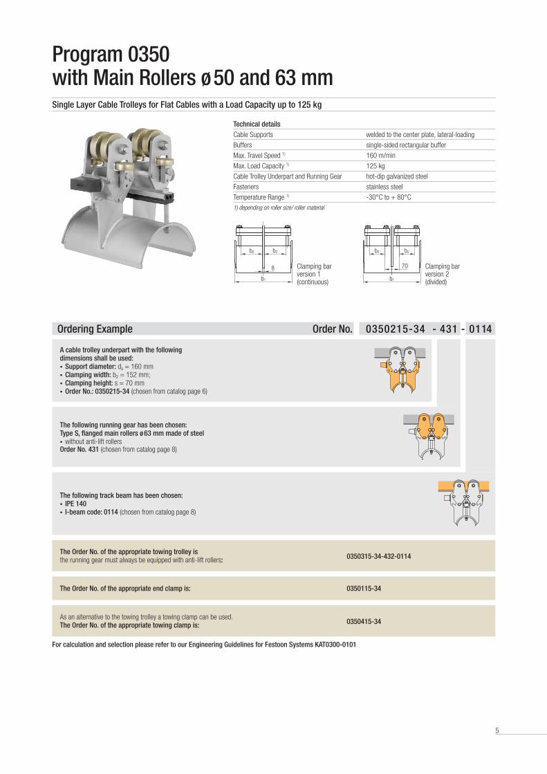
Program 0350 with Main Rollers ø 50 and 63 mmSingle Layer Cable Trolleys for Flat Cables with a Load Capacity up to 125 kg
Technical detailsCable Supports welded to the center plate, lateral-loading
Buffers single-sided rectangular buffer
Max . Travel Speed 1) 160 m/min
Max . Load Capacity 1) 125 kg
Cable Trolley Underpart and Running Gear hot-dip galvanized steel
Fasteners stainless steel
Temperature Range 1) -30°C to + 80°C 1) depending on roller size/ roller material
b2b2
b1
8 Clamping bar version 1 (continuous)
b2b2
b1
70 Clamping bar version 2 (divided)
Ordering Example Order No. 0350215-34 - 431 - 0114
A cable trolley underpart with the following dimensions shall be used:• Support diameter: da = 160 mm • Clamping width: b2 = 152 mm; • Clamping height: s = 70 mm• Order No.: 0350215-34 (chosen from catalog page 6)
The following running gear has been chosen:Type S, flanged main rollers ø 63 mm made of steel• without anti-lift rollersOrder No. 431 (chosen from catalog page 8)
The following track beam has been chosen:• IPE 140• I-beam code: 0114 (chosen from catalog page 8)
The Order No. of the appropriate towing trolley is the running gear must always be equipped with anti-lift rollers: 0350315-34-432-0114
The Order No. of the appropriate end clamp is: 0350115-34
As an alternative to the towing trolley a towing clamp can be used .The Order No. of the appropriate towing clamp is: 0350415-34
For calculation and selection please refer to our Engineering Guidelines for Festoon Systems KAT0300-0101
6
ø da
b2s 8
b1
23
45
lW
k
~h a
~h Wø 13
b2s 8
b1
2357
lM
~112
140
ø 13
lM + 62lMF
35
ø da
Cable Trolley Underpart1)
Towing Trolley Underpart1)
da lw b1 b2 s k Clamping Bar Version
ha hw lM lMF
Order No. [kg] Order No. [kg] [mm] [mm] [mm] [mm] [mm] [mm] [mm] [mm] [mm] [mm]
0350213-20 4 .0 0350313-20 5 .1
125
250
215 72
52
158
1 185
250 102 129
0350213-22 4 .4 0350313-22 5 .5 280 105
0350213-24 5 .2 0350313-24 6 .0 375 152
0350212-30 4 .1 0350312-30 5 .2
160
215 72
35 1 1700350212-32 4 .5 0350312-32 5 .6 280 105
0350212-34 5 .2 0350312-34 6 .3 375 152
0350215-30 5 .2 0350315-30 6 .4
320
215 72
70
228
1 200
280 137 164
0350215-32 5 .7 0350315-32 6 .8 280 105
0350215-34 6 .4 0350315-34 7 .5 375 152
0350213-40 5 .2 0350313-40 6 .5
200
215 72
52
1
1800350213-42 5 .7 0350313-42 7 .0 280 105 1
0350223-43 6 .7 0350323-43 7 .6 375 125 2
0350213-44 6 .4 0350313-44 7 .8 375 152 1
0350216-42 7 .3 0350316-42 8 .4
400
280 105
90
308
1
215
315 177 204
0350226-43 8 .3 0350326-43 9 .4 375 125 2
0350216-44 8 .0 0350316-44 9 .1 375 152 1
0350214-50 6 .6 0350314-50 7 .7
250
215 72
65
1
1900350214-52 7 .1 0350314-52 8 .6 280 105 1
0350224-53 8 .1 0350324-53 9 .6 375 125 2
0350214-54 8 .1 0350314-54 9 .3 375 152 1
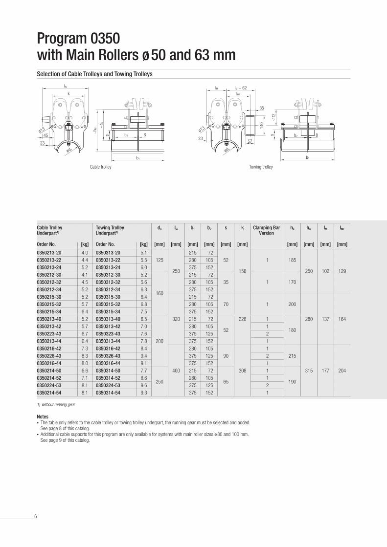
Program 0350 with Main Rollers ø 50 and 63 mmSelection of Cable Trolleys and Towing Trolleys
Cable trolley Towing trolley
1) without running gear
Notes• The table only refers to the cable trolley or towing trolley underpart, the running gear must be selected and added .
See page 8 of this catalog .• Additional cable supports for this program are only available for systems with main roller sizes ø 80 and 100 mm .
See page 9 of this catalog .
7
90
s 8
b1
60
lE3
lE
52
ø 13
lE2
k
30
83
34
ø 13
ø 11
b2
ø da
s 8
b1
23
31
115
ø 13
63
lk
125
21
50
ø 13
b2
ø 9
120
25
8
ø da
Cable Trolley Underpart1)
Towing Trolley Underpart1)
da lw b1 b2 s k Clamping Bar Version
ha hw lM lMF
Order No. [kg] Order No. [kg] [mm] [mm] [mm] [mm] [mm] [mm] [mm] [mm] [mm] [mm]
0350213-20 4 .0 0350313-20 5 .1
125
250
215 72
52
158
1 185
250 102 129
0350213-22 4 .4 0350313-22 5 .5 280 105
0350213-24 5 .2 0350313-24 6 .0 375 152
0350212-30 4 .1 0350312-30 5 .2
160
215 72
35 1 1700350212-32 4 .5 0350312-32 5 .6 280 105
0350212-34 5 .2 0350312-34 6 .3 375 152
0350215-30 5 .2 0350315-30 6 .4
320
215 72
70
228
1 200
280 137 164
0350215-32 5 .7 0350315-32 6 .8 280 105
0350215-34 6 .4 0350315-34 7 .5 375 152
0350213-40 5 .2 0350313-40 6 .5
200
215 72
52
1
1800350213-42 5 .7 0350313-42 7 .0 280 105 1
0350223-43 6 .7 0350323-43 7 .6 375 125 2
0350213-44 6 .4 0350313-44 7 .8 375 152 1
0350216-42 7 .3 0350316-42 8 .4
400
280 105
90
308
1
215
315 177 204
0350226-43 8 .3 0350326-43 9 .4 375 125 2
0350216-44 8 .0 0350316-44 9 .1 375 152 1
0350214-50 6 .6 0350314-50 7 .7
250
215 72
65
1
1900350214-52 7 .1 0350314-52 8 .6 280 105 1
0350224-53 8 .1 0350324-53 9 .6 375 125 2
0350214-54 8 .1 0350314-54 9 .3 375 152 1
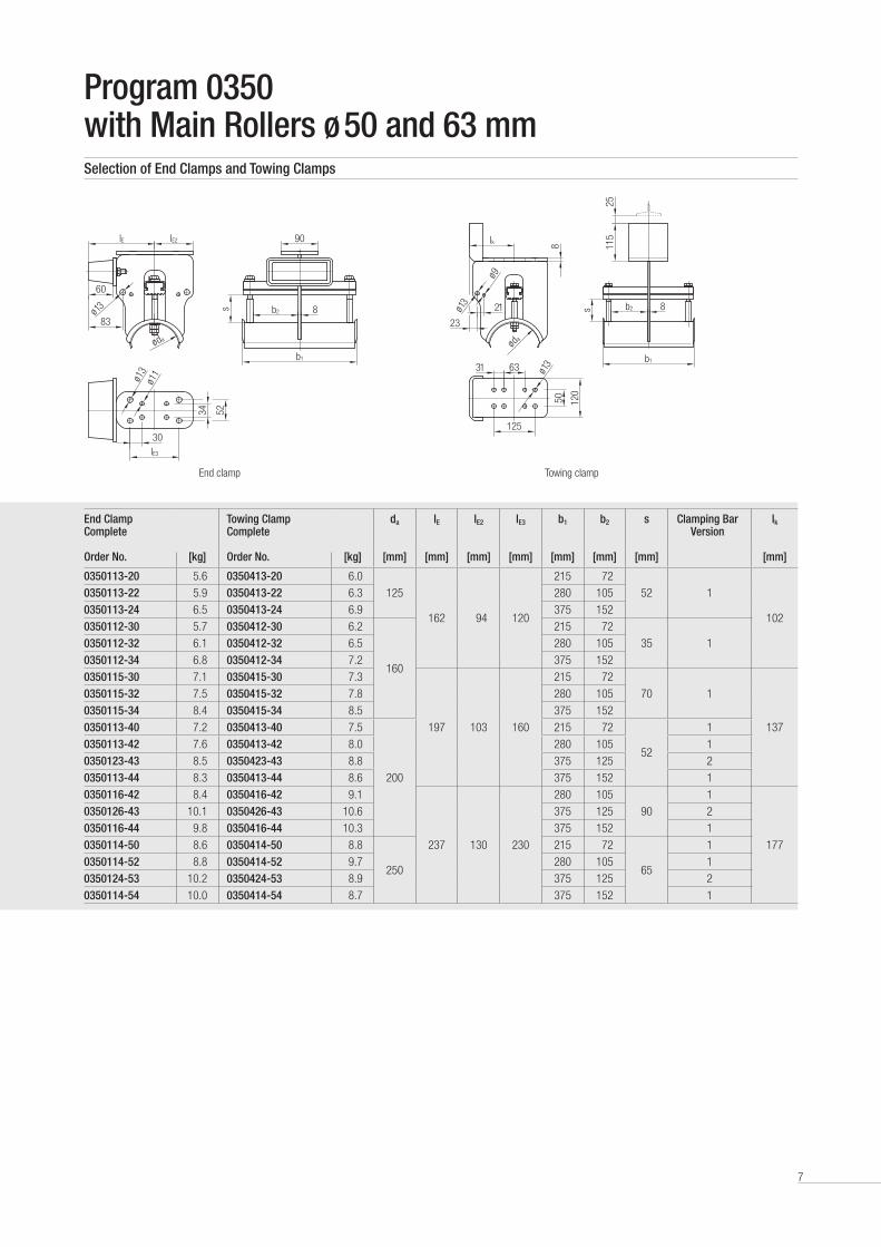
Program 0350 with Main Rollers ø 50 and 63 mmSelection of End Clamps and Towing Clamps
End clamp Towing clamp
End Clamp Complete
Towing Clamp Complete
da lE lE2 lE3 b1 b2 s Clamping Bar Version
lk
Order No. [kg] Order No. [kg] [mm] [mm] [mm] [mm] [mm] [mm] [mm] [mm]
0350113-20 5 .6 0350413-20 6 .0
125
162 94 120
215 72
52 1
102
0350113-22 5 .9 0350413-22 6 .3 280 105
0350113-24 6 .5 0350413-24 6 .9 375 152
0350112-30 5 .7 0350412-30 6 .2
160
215 72
35 10350112-32 6 .1 0350412-32 6 .5 280 105
0350112-34 6 .8 0350412-34 7 .2 375 152
0350115-30 7 .1 0350415-30 7 .3
197 103 160
215 72
70 1
137
0350115-32 7 .5 0350415-32 7 .8 280 105
0350115-34 8 .4 0350415-34 8 .5 375 152
0350113-40 7 .2 0350413-40 7 .5
200
215 72
52
1
0350113-42 7 .6 0350413-42 8 .0 280 105 1
0350123-43 8 .5 0350423-43 8 .8 375 125 2
0350113-44 8 .3 0350413-44 8 .6 375 152 1
0350116-42 8 .4 0350416-42 9 .1
237 130 230
280 105
90
1
177
0350126-43 10 .1 0350426-43 10 .6 375 125 2
0350116-44 9 .8 0350416-44 10 .3 375 152 1
0350114-50 8 .6 0350414-50 8 .8
250
215 72
65
1
0350114-52 8 .8 0350414-52 9 .7 280 105 1
0350124-53 10 .2 0350424-53 8 .9 375 125 2
0350114-54 10 .0 0350414-54 8 .7 375 152 1

8
Program 0350 with Main Rollers ø 50 and 63 mmSelection of Running Gear
Note/design• The running gear of the towing trolley must always be equipped with anti-lift rollers .• The anti-lift rollers ø 40 mm are made of steel .• The horizontal guide rollers ø 40 mm are made of steel .• Other materials of the horizontal guide rollers, e .g . Polyurethane on request .• The rollers are equipped with precision ball bearings and additional sealing disks (2RS1) . The ball bearings are lifetime lubricated .• Running gear for other I-beam types or beam sizes on request .
Running Gear Order No.
Main Roller Weight approx.
[kg]
Preference Range I-beamsød
[mm]Material Bandage
Parallel Flange
I-beam Code
Tapered Flange
I-beam Code
Type H with cylindrical main rollers
311 50 Steel 3 .8- - INP 120 0012
351 50 Polyurethane 3 .5411 63 Steel 5 .1
- - INP 120INP 140
00120014451 63 Polyurethane 4 .7
Type HG with cylindrical main rollers and anti-lift rollers
312 50 Steel 4 .3- - INP 120 0012
352 50 Polyurethane 4 .1412 63 Steel 5 .6 -
---
INP 120INP 140
00120014452 63 Polyurethane 4 .9
Type HF with cylindrical main rollers and horizontal guide rollers
313 50 Steel 4 .0 IPE 100IPE 120IPE 140IPE 160IPE 180
01100112011401160118
-INP 120INP 140INP 160INP 180
-0012001400160018357 50 Polyurethane 3 .8
413 63 Steel 5 .1 IPE 120IPE 140IPE 160IPE 180IPE 200
01120114011601180120
INP 120INP 140INP 160INP 180
-
0012001400160018
-457 63 Polyurethane 4 .4
Type HFG with cylindrical main rollers, horizontal guide rollers and anti-lift rollers
314 50 Steel 4 .5 IPE 100IPE 120IPE 140IPE 160IPE 180
01100112011401160118
-INP 120INP 140INP 160INP 180
-0012001400160018358 50 Polyurethane 4 .0
414 63 Steel 5 .6 IPE 120IPE 140IPE 160IPE 180IPE 200
01120114011601180120
INP 120INP 140INP 160INP 180
-
0012001400160018
-458 63 Polyurethane 4 .9
Type S with flanged main rollers
331 50 Steel 4 .2
IPE 100IPE 120IPE 140IPE 160IPE 180
01100112011401160118
-INP 120INP 140INP 160INP 180
-0012001400160018
431 63 Steel 5 .5
IPE 120IPE 140IPE 160IPE 180IPE 200
01120114011601180120
INP 120INP 140INP 160INP 180
-
0012001400160018
-
Type SG with flanged main rollers and anti-lift rollers
332 50 Steel 4 .4
IPE 100IPE 120IPE 140IPE 160IPE 180
01100112011401160118
-INP 120INP 140INP 160INP 180
-0012001400160018
432 63 Steel 6 .1
IPE 120IPE 140IPE 160IPE 180IPE 200
01120114011601180120
INP 120INP 140INP 160INP 180
-
0012001400160018
-
9
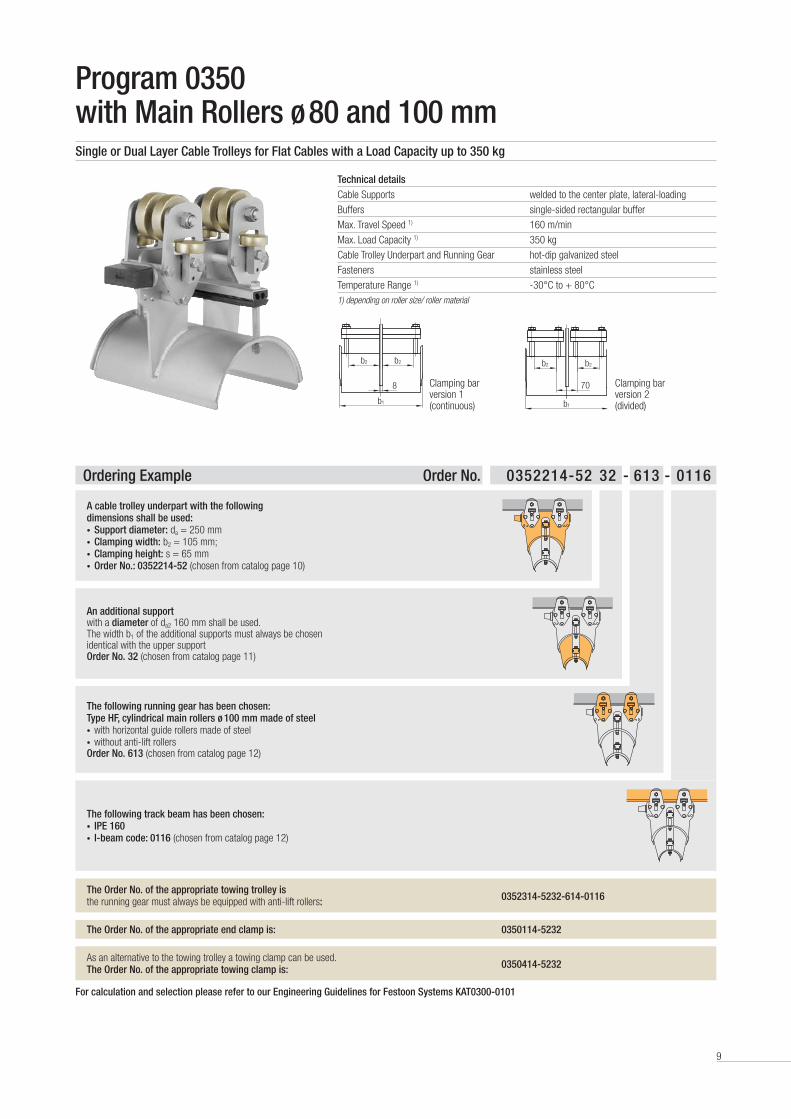
Program 0350 with Main Rollers ø 80 and 100 mmSingle or Dual Layer Cable Trolleys for Flat Cables with a Load Capacity up to 350 kg
Technical detailsCable Supports welded to the center plate, lateral-loading
Buffers single-sided rectangular buffer
Max . Travel Speed 1) 160 m/min
Max . Load Capacity 1) 350 kg
Cable Trolley Underpart and Running Gear hot-dip galvanized steel
Fasteners stainless steel
Temperature Range 1) -30°C to + 80°C1) depending on roller size/ roller material
b2b2
b1
8 Clamping bar version 1 (continuous)
b2b2
b1
70 Clamping bar version 2 (divided)
Ordering Example Order No. 0352214-52 32 - 613 - 0116
A cable trolley underpart with the following dimensions shall be used:• Support diameter: da = 250 mm • Clamping width: b2 = 105 mm; • Clamping height: s = 65 mm• Order No.: 0352214-52 (chosen from catalog page 10)
An additional support with a diameter of da2 160 mm shall be used . The width b1 of the additional supports must always be chosen identical with the upper supportOrder No. 32 (chosen from catalog page 11)
The following running gear has been chosen:Type HF, cylindrical main rollers ø 100 mm made of steel• with horizontal guide rollers made of steel• without anti-lift rollersOrder No. 613 (chosen from catalog page 12)
The following track beam has been chosen:• IPE 160• I-beam code: 0116 (chosen from catalog page 12)
The Order No. of the appropriate towing trolley is the running gear must always be equipped with anti-lift rollers: 0352314-5232-614-0116
The Order No. of the appropriate end clamp is: 0350114-5232
As an alternative to the towing trolley a towing clamp can be used .The Order No. of the appropriate towing clamp is: 0350414-5232
For calculation and selection please refer to our Engineering Guidelines for Festoon Systems KAT0300-0101

10
b2s 8
b1
2357
lM
~112
140
ø 13
lM + 62lMF
35
øda
b2s 8
b1
23
45
lW
k
~h a
~h W
ø 13
ø da
Cable Trolley Underpart1)
Towing Trolley Underpart1)
da lw b1 b2 s k Clamping Bar
Version
ha hw lM lMF
Order No. [kg] Order No. [kg] [mm] [mm] [mm] [mm] [mm] [mm] [mm] [mm] [mm] [mm]
0352215-30 5 .2 0352315-30 6 .6
160
320
215 72
70
228
1
215
295 137 164
0352215-32 5 .7 0352315-32 7 .0 280 105 1
0352215-34 6 .4 0352315-34 7 .7 375 152 1
0352213-40 5 .2 0352313-40 6 .8
200
215 72
52
1
1950352213-42 5 .7 0352313-42 7 .2 280 105 1
0352223-43 6 .7 0352323-43 8 .0 375 125 2
0352213-44 6 .4 0352313-44 7 .8 375 152 1
0352216-42 7 .3 0352316-42 7 .9
400
280 105
90
308
1
215
315 177 204
0352226-43 8 .3 0352326-43 9 .4 375 125 2
0352216-44 8 .0 0352316-44 9 .1 375 152 1
0352214-50 6 .6 0352314-50 8 .1
250
215 72
65
1
1900352214-52 7 .1 0352314-52 8 .4 280 105 1
0352224-53 8 .1 0352324-53 9 .4 375 125 2
0352214-54 8 .1 0352314-54 9 .2 375 152 1
Program 0350 with Main Rollers ø 80 and 100 mmSelection of Cable Trolleys and Towing Trolleys
1) without running gear
Cable trolley Towing trolley
Notes• The table only refers to the cable trolley or towing trolley underpart, the running gear must be selected and added .
See page 12 of this catalog .• The system components can be equipped with one or two additional supports . See page 11 of this catalog .

11
s 8
b1
23
31
115
ø 13
63
lk
125
21
50
ø 13
b2
ø 9
120
25
8
ø da
90s 8
b1
60
lE3
lE52
ø 13
lE2
k
30
83
34
ø 13
ø 11
b2
ø da
23
45
lW
k
ø 13
ø da2
ø da
h z1-
2
s 2s
Cable Trolley Underpart1)
Towing Trolley Underpart1)
da lw b1 b2 s k Clamping Bar
Version
ha hw lM lMF
Order No. [kg] Order No. [kg] [mm] [mm] [mm] [mm] [mm] [mm] [mm] [mm] [mm] [mm]
0352215-30 5 .2 0352315-30 6 .6
160
320
215 72
70
228
1
215
295 137 164
0352215-32 5 .7 0352315-32 7 .0 280 105 1
0352215-34 6 .4 0352315-34 7 .7 375 152 1
0352213-40 5 .2 0352313-40 6 .8
200
215 72
52
1
1950352213-42 5 .7 0352313-42 7 .2 280 105 1
0352223-43 6 .7 0352323-43 8 .0 375 125 2
0352213-44 6 .4 0352313-44 7 .8 375 152 1
0352216-42 7 .3 0352316-42 7 .9
400
280 105
90
308
1
215
315 177 204
0352226-43 8 .3 0352326-43 9 .4 375 125 2
0352216-44 8 .0 0352316-44 9 .1 375 152 1
0352214-50 6 .6 0352314-50 8 .1
250
215 72
65
1
1900352214-52 7 .1 0352314-52 8 .4 280 105 1
0352224-53 8 .1 0352324-53 9 .4 375 125 2
0352214-54 8 .1 0352314-54 9 .2 375 152 1
End Clamp Complete
Towing Clamp Complete
da lE lE2 lE3 b1 b2 s Clamping Bar
Version
lk
Order No. [kg] Order No. [kg] [mm] [mm] [mm] [mm] [mm] [mm] [mm] [mm]
0350115-30 7 .1 0350415-30 7 .3
160
197 103 160
215 72
70
1
137
0350115-32 7 .5 0350415-32 7 .8 280 105 1
0350115-34 8 .4 0350415-34 8 .5 375 152 1
0350113-40 7 .2 0350413-40 7 .5
200
215 72
52
1
0350113-42 7 .6 0350413-42 8 .0 280 105 1
0350123-43 8 .5 0350423-43 8 .8 375 125 2
0350113-44 8 .3 0350413-44 8 .6 375 152 1
0350116-42 8 .4 0350416-42 9 .1
237 130 230
280 105
90
1
177
0350126-43 10 .1 0350426-43 10 .6 375 125 2
0350116-44 9 .8 0350416-44 10 .3 375 152 1
0350114-50 8 .6 0350414-50 8 .8
250
215 72
65
1
0350114-52 8 .8 0350414-52 9 .7 280 105 1
0350124-53 10 .2 0350424-53 8 .9 375 125 2
0350114-54 10 .0 0350414-54 8 .7 375 152 1
Program 0350 with Main Rollers ø 80 and 100 mmSelection of End Clamps and Towing Clamps
Additional Support da da2 b1 b2 s2 Clamping Bar
Version
hZ1-2 Order No.
[kg]
[mm]
[mm]
[mm]
[mm]
[mm]
[mm]
20 2 .8
200 125
215 72
35
1
17022 3 .2 280 105 1
23 3 .8 375 125 2
24 3 .7 375 152 1
30 3 .0
250 160
215 72
35
1
17032 3 .4 280 105 1
33 4 .2 375 125 2
34 4 .1 375 152 1
The support width as well as the clamping bar design of the additional support must correspond to the upper sup-port of the cable trolley .
End clamp Towing clamp
Additional Supports

12
Program 0350 with Main Rollers ø 80 and 100 mmSelection of Running Gear
Note/design• The running gear of the towing trolley must always be equipped with anti-lift rollers .• Main roller ø 80 mm: anti-lift rollers ø 50 mm and horiziontal guide rollers ø 50 mm made of steel• Main roller ø 100 mm: anti-lift rollers ø 50 mm and horiziontal guide rollers ø 63 mm made of steel• Other materials of the horizontal guide rollers, e .g . Polyurethane on request .• The rollers are equipped with precision ball bearings and additional sealing disks (2RS1) .
The ball bearings are lifetime lubricated .• Running gear for other I-beam types or beam sizes on request .
Running Gear Order No.
Main Roller Weight approx.
[kg]
Preference Range I-beamsød
[mm]Material Bandage
Parallel Flange
I-beam Code
Tapered Flange
I-beam Code
Type H with cylindrical main rollers
511 80 Steel 8 .3- - INP 140
INP 16000140016551 80 Polyurethane 7 .7
611 100 Steel 12 .3- -
INP 140INP 160INP 180
001400160018651 100 Polyurethane 11 .8
Type HG with cylindrical main rollers and anti-lift rollers
512 80 Steel 9 .5- - INP 140
INP 16000140016552 80 Polyurethane 8 .1
612 100 Steel 13 .8- -
INP 140INP 160INP 180
001400160018652 100 Polyurethane 13 .3
Type HF with cylindrical main rollers and horizontal guide rollers
513 80 Steel 9 .7 IPE 140IPE 160IPE 180IPE 200
0114011601180120
INP 140INP 160INP 180INP 200
0014001600180020557 80 Polyurethane 8 .3
613 100 Steel 13 .3 IPE 160IPE 180IPE 200IPE 220IPE 240
01160118012001220124
INP 160INP 180INP 200INP 220INP 240
00160018002000220024657 100 Polyurethane 12 .8
Type HFG with cylindrical main rollers, horizontal guide rollers and anti-lift rollers
514 80 Steel 9 .8 IPE 140IPE 160IPE 180IPE 200
0114011601180120
INP 140INP 160INP 180INP 200
0014001600180020558 80 Polyurethane 9 .3
614 100 Steel 14 .3 IPE 160IPE 180IPE 200IPE 220IPE 240
01160118012001220124
INP 160INP 180INP 200INP 220INP 240
00160018002000220024658 100 Polyurethane 13 .8
Type S with flanged main rollers
531 80 Steel 9 .9
IPE 140IPE 160IPE 180IPE 200
0114011601180120
INP 140INP 160INP 180INP 200
0014001600180020
631 100 Steel 16 .0
IPE 160IPE 180IPE 200IPE 220IPE 240
01160118012001220124
INP 160INP 180INP 200INP 220INP 240
00160018002000220024
Type SG with flanged main rollers and anti-lift rollers
532 80 Steel 11 .3
IPE 140IPE 160IPE 180IPE 200
0114011601180120
INP 140INP 160INP 180INP 200
0014001600180020
632 100 Steel 17 .3
IPE 160IPE 180IPE 200IPE 220IPE 240
01160118012001220124
INP 160INP 180INP 200INP 220INP 240
00160018002000220024

13
Program 0360 with Main Rollers ø 50 and 63 mmSingle or Dual Layer Cable Trolleys for Round Cables with a Load Capacity up to 125 kg
Technical detailsCable Supports bolted to the center plate, lateral-loading
Buffers single-sided rectangular buffer
Max . Travel Speed 1) 160 m/min
Max . Load Capacity 1) 125 kg
Cable Trolley Underpart and Running Gear hot-dip galvanized steel
Fasteners stainless steel
Temperature Range 1) -30°C to + 80°C 1) depending on roller size/ roller material
b2b2
b1
8 Clamping bar version 1 (continuous)
b2b2
b1
70 Clamping bar version 2 (divided)
Ordering Example Order No. 036022-86 66 - 414 - 0014
A cable trolley underpart with the following dimensions shall be used:• Support diameter: da = 360 mm • Clamping width: b2 = 200 mm; • Clamping height: s = 36 mm• Order No.: 036022-86 (chosen from catalog page 14)
An additional support with a diameter da2 260 mm shall be used . The width b1 of the additional supports must always be chosen identical with the upper supportOrder No. 66 (chosen from catalog page 15)
The following running gear has been chosen:Type HFG, cylindrical main rollers ø 63 mm, made of steel• with horizontal guide rollers made of steel• with anti-lift rollers made of steelOrder No. 414 (chosen from catalog page 16
The following track beam has been chosen:• INP 140• I-beam code: 0014 (chosen from catalog page 16)
The Order No. of the appropriate towing trolley is the running gear must always be equipped with anti-lift rollers: 036032-8666-414-0014
The Order No. of the appropriate end clamp is: 036012-8666
As an alternative to the towing trolley a towing clamp can be used .The Order No. of the appropriate towing clamp is: 036042-8666
For calculation and selection please refer to our Engineering Guidelines for Festoon Systems KAT0300-0101

14
b1
~h w
klw
8b2
~h a
s
68
45
ø 13
ø da
ø 13
ø da
b1
~116
lM
8b2
s70
lMF
101
110
23
b1
~116
lM
8b2
s
70
ø 13
lMF
25
110
23
ø da
Cable Trolley Underpart1)
Towing Trolley Underpart1)
da lw b1 b2 s k Clamping Bar
Version
ha hw lM lMF
Order No. [kg] Order No. [kg] [mm] [mm] [mm] [mm] [mm] [mm] [mm] [mm] [mm] [mm]
036021-62 8 .2 036031-62 11 .5
260 334
291 110
26 242
1
150 276 170 172036021-64 9 .4 036031-64 14 .2 384 155 1
036022-66 12 .2 036032-66 15 .8 532 200 2
036022-68 13 .4 036032-68 17 .1 632 250 2
036021-82 10 .6 036031-82 17 .0
360 454
291 110
36 362
1
160 336 239 241036021-84 12 .0 036031-84 18 .6 384 155 1
036022-86 15 .7 036032-86 22 .6 532 200 2
036022-88 17 .3 036032-88 24 .3 632 250 2
036021-92 13 .7 036031-92 23 .2
460 574
291 110
46 482
1
180 410 309 165036021-94 15 .7 036031-94 25 .0 384 155 1
036022-96 20 .5 036032-96 30 .4 532 200 2
036022-98 21 .1 036032-98 31 .9 632 250 2
Program 0360 with Main Rollers ø 50 and 63 mmSelection of Cable Trolleys and Towing Trolleys
1) without running gear
Cable trolley Towing trolley da 260 mm and 360 mm
Towing trolley da 460 mm
Notes• The table only refers to the cable trolley or towing trolley underpart, the running gear must be selected and added .
See page 16 of this catalog .• The system components can be equipped with an additional support .
See page 15 of this catalog .
15
IE
s
IE2 70
8b2
IE3
83
60
ø 11
ø 11
ø da
X2530
b1
ø 1360
4530
X
Cable Trolley Underpart1)
Towing Trolley Underpart1)
da lw b1 b2 s k Clamping Bar
Version
ha hw lM lMF
Order No. [kg] Order No. [kg] [mm] [mm] [mm] [mm] [mm] [mm] [mm] [mm] [mm] [mm]
036021-62 8 .2 036031-62 11 .5
260 334
291 110
26 242
1
150 276 170 172036021-64 9 .4 036031-64 14 .2 384 155 1
036022-66 12 .2 036032-66 15 .8 532 200 2
036022-68 13 .4 036032-68 17 .1 632 250 2
036021-82 10 .6 036031-82 17 .0
360 454
291 110
36 362
1
160 336 239 241036021-84 12 .0 036031-84 18 .6 384 155 1
036022-86 15 .7 036032-86 22 .6 532 200 2
036022-88 17 .3 036032-88 24 .3 632 250 2
036021-92 13 .7 036031-92 23 .2
460 574
291 110
46 482
1
180 410 309 165036021-94 15 .7 036031-94 25 .0 384 155 1
036022-96 20 .5 036032-96 30 .4 532 200 2
036022-98 21 .1 036032-98 31 .9 632 250 2
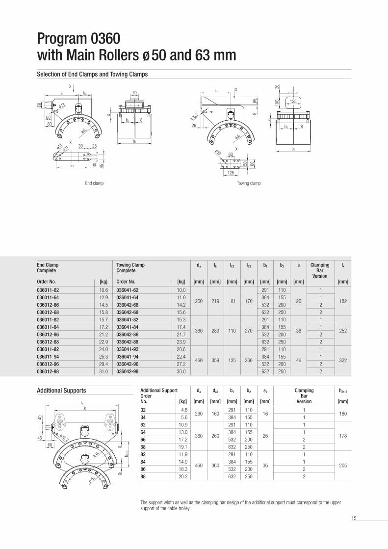
Program 0360 with Main Rollers ø 50 and 63 mmSelection of End Clamps and Towing Clamps
Additional Support da da2 b1 b2 s2 Clamping Bar
Version
hZ1-2 Order No.
[kg]
[mm]
[mm]
[mm]
[mm]
[mm]
[mm]
32 4 .8260 160
291 11016
1180
34 5 .6 384 155 1
62 10 .9
360 260
291 110
26
1
17864 13 .0 384 155 1
66 17 .2 532 200 2
68 19 .1 632 250 2
82 11 .9
460 360
291 110
36
1
20584 14 .0 384 155 1
86 18 .3 532 200 2
88 20 .2 632 250 2
The support width as well as the clamping bar design of the additional support must correspond to the upper support of the cable trolley .
End clamp Towing clamp
Additional Supports
End Clamp Complete
Towing Clamp Complete
da lE lE2 lE3 b1 b2 s Clamping Bar
Version
lk
Order No. [kg] Order No. [kg] [mm] [mm] [mm] [mm] [mm] [mm] [mm] [mm]
036011-62 10 .6 036041-62 10 .0
260 219 81 170
291 110
26
1
182036011-64 12 .9 036041-64 11 .8 384 155 1
036012-66 14 .5 036042-66 14 .2 532 200 2
036012-68 15 .8 036042-68 15 .6 632 250 2
036011-82 15 .7 036041-82 15 .3
360 289 110 270
291 110
36
1
252036011-84 17 .2 036041-84 17 .4 384 155 1
036012-86 21 .2 036042-86 21 .7 532 200 2
036012-88 22 .9 036042-88 23 .9 632 250 2
036011-92 24 .0 036041-92 20 .6
460 359 125 360
291 110
46
1
322036011-94 25 .3 036041-94 22 .4 384 155 1
036012-96 29 .4 036042-96 27 .2 532 200 2
036012-98 31 .0 036042-98 30 .0 632 250 2
Ik
s
100
30
865
8050
b1
125
63
26 b2 8
125
ø da
ø16.2
ø 13
X
X
Iw
40
ø da
ø da2
k
68
45ø 16.2
h z1-
2
s 2s

16
Program 0360 with Main Rollers ø 50 and 63 mmSelection of Running Gear
Note/design• The running gear of the towing trolley must always be equipped with anti-lift rollers .• The anti-lift rollers ø 40 mm are made of steel .• The horizontal guide rollers ø 40 mm are made of steel . • Other materials of the horizontal guide rollers, e .g . Polyurethane on request .• The rollers are equipped with precision ball bearings and additional sealing disks (2RS1) . The ball bearings are lifetime lubricated .• Running gear for other I-beam types or beam sizes on request .
Running Gear Order No.
Main Roller Weight approx.
[kg]
Preference Range I-beamsød
[mm]Material Binding
Parallel Flange
I-beam Code
Tapered Flange
I-beam Code
Typ H mit zylindrischen Haupttragrollen
311 50 Steel 3 .8- - INP 120 0012
351 50 Polyurethane 3 .5
411 63 Steel 5 .1 --
--
INP 120INP 140
00120014451 63 Polyurethane 4 .7
Typ HG mit zylindrischen Haupttragrollen und Gegendruckrollen
312 50 Steel 4 .3- - INP 120 0012
352 50 Polyurethane 4 .1
412 63 Steel 5 .6 --
--
INP 120INP 140
00120014452 63 Polyurethane 4 .9
Typ HF mit zylindrischen Haupttragrollen und horizontalen Führungsrollen
313 50 Steel 4 .0 IPE 100IPE 120IPE 140IPE 160IPE 180
01100112011401160118
-INP 120INP 140INP 160INP 180
-0012001400160018357 50 Polyurethane 3 .8
413 63 Steel 5 .1 IPE 120IPE 140IPE 160IPE 180IPE 200
01120114011601180120
INP 120INP 140INP 160INP 180
-
0012001400160018
-457 63 Polyurethane 4 .4
Typ HFG mit zylindrischen Haupttragrollenhorizontalen Führungsrollen und Gegendruckrollen
314 50 Steel 4 .5 IPE 100IPE 120IPE 140IPE 160IPE 180
01100112011401160118
-INP 120INP 140INP 160INP 180
-0012001400160018358 50 Polyurethane 4 .0
414 63 Steel 5 .6 IPE 120IPE 140IPE 160IPE 180IPE 200
01120114011601180120
INP 120INP 140INP 160INP 180
-
0012001400160018
-458 63 Polyurethane 4 .9
Typ S mit Spurkranz- Haupttragrollen
331 50 Steel 4 .2
IPE 100IPE 120IPE 140IPE 160IPE 180
01100112011401160118
-INP 120INP 140INP 160INP 180
-0012001400160018
431 63 Steel 5 .5
IPE 120IPE 140IPE 160IPE 180IPE 200
01120114011601180120
INP 120INP 140INP 160INP 180
-
0012001400160018
-
Typ SG mit Spurkranz- Haupttragrollen und Gegendruckrollen
332 50 Steel 4 .4
IPE 100IPE 120IPE 140IPE 160IPE 180
01100112011401160118
-INP 120INP 140INP 160INP 180
-0012001400160018
432 63 Steel 6 .1
IPE 120IPE 140IPE 160IPE 180IPE 200
01120114011601180120
INP 120INP 140INP 160INP 180
-
0012001400160018
-

17
Program 0360 with Main Rollers ø 80, 100, 112 and 125 mmSingle, Dual or Tripple Layer Cable Trolleys for Round Cabes with a Load Capacity up to 500 kg
Ordering Example Order No. 036222-96 8666 - 658 - 0018
A cable trolley underpart with the following dimensions shall be used:• Support diameter: da = 460 mm • Clamping width: b2 = 200 mm; • Clamping height: s = 46 mm• Order No.: 036222-96 (chosen from catalog page 18)
Two additional supports with a diameter da2 360 mm and da3 260 mm shall be used . The width b1 of the additional supports must always be chosen identical with the upper supportOrder No. 8666 (chosen from catalog page 19)
The following running gear has been chosen:Type HFG, cylindrical main rollers ø 100 mm with Polyurethane bandage• with horizontal guide rollers made of steel• with anti-lift rollers made of steelOrder No. 658 (chosen from catalog page 20)
The following track beam has been chosen:• INP 180• I-beam code: 0018 (chosen from catalog page 20)
The Order No. of the appropriate towing trolley is the running gear must always be equipped with anti-lift rollers: 036232-968666-658-0018
The Order No. of the appropriate end clamp is: 036212-968666
As an alternative to the towing trolley a towing clamp can be used .The Order No. of the appropriate towing clamp is: 036042-968666
For calculation and selection please refer to our Engineering Guidelines for Festoon Systems KAT0300-0101
Technical detailsCable Supports bolted to the center plate, lateral-loading
Buffers single-sided round buffer
Max . Travel Speed 1) 160 m/min
Max . Load Capacity 1) 500 kg
Cable Trolley Underpart and Running Gear hot-dip galvanized steel
Fasteners stainless steel
Temperature Range 1) -30°C to + 80°C 1) depending on roller size/ roller material
b2b2
b1
8 Clamping bar version 1 (continuous)
b2b2
b1
70 Clamping bar version 2 (divided)

18
Cable Trolley Underpart1)
Towing Trolley Underpart1)
da lw b1 b2 s k Clamping Bar
Version
ha hw lM lMF
Order No. [kg] Order No. [kg] [mm] [mm] [mm] [mm] [mm] [mm] [mm] [mm] [mm] [mm]
036221-62 10 .8 036231-62 11 .4
260 350
291 110
26 235
1
200 326 170 218
036221-64 12 .6 036231-64 13 .2 384 155 1
036222-66 15 .2 036232-66 15 .6 532 200 2
036222-68 16 .3 036232-68 16 .9 632 250 2
036222-69 18 .7 036232-69 17 .8 772 320 2
036221-82 14 .9 036231-82 19 .0
360 470
291 110
36 355
1
210 388 239 288
036221-84 17 .2 036231-84 19 .6 384 155 1
036222-86 22 .0 036232-86 23 .9 532 200 2
036222-88 23 .9 036232-88 25 .8 632 250 2
036222-89 26 .8 036232-89 28 .7 772 320 2
036221-92 21 .6 036231-92 23 .9
460 590
291 110
46 475
1
220 448 310 358
036221-94 23 .3 036231-94 25 .7 384 155 1
036222-96 28 .8 036232-96 31 .1 532 200 2
036222-98 30 .9 036232-98 33 .2 632 250 2
036222-99 34 .2 036232-99 36 .5 772 320 2
Program 0360 with Main Rollers ø 80, 100, 112 and 125 mmSelection of Cable Trolleys and Towing Trolleys
1) without running gear
Cable trolley Towing trolley
Iw
s
k
8b2
63
ø da
26
b1
ø 16.2
ø80
~h a
~h w26
IM
s
8b290
ø da
30
b1
ø 16.2
~116
26
IMF
140
Notes• The table only refers to the cable trolley or towing trolley underpart, the running gear must be selected and added .
See page 20 of this catalog .• The system components can be equipped with one or two additional supports .
See page 19 of this catalog .
19
Cable Trolley Underpart1)
Towing Trolley Underpart1)
da lw b1 b2 s k Clamping Bar
Version
ha hw lM lMF
Order No. [kg] Order No. [kg] [mm] [mm] [mm] [mm] [mm] [mm] [mm] [mm] [mm] [mm]
036221-62 10 .8 036231-62 11 .4
260 350
291 110
26 235
1
200 326 170 218
036221-64 12 .6 036231-64 13 .2 384 155 1
036222-66 15 .2 036232-66 15 .6 532 200 2
036222-68 16 .3 036232-68 16 .9 632 250 2
036222-69 18 .7 036232-69 17 .8 772 320 2
036221-82 14 .9 036231-82 19 .0
360 470
291 110
36 355
1
210 388 239 288
036221-84 17 .2 036231-84 19 .6 384 155 1
036222-86 22 .0 036232-86 23 .9 532 200 2
036222-88 23 .9 036232-88 25 .8 632 250 2
036222-89 26 .8 036232-89 28 .7 772 320 2
036221-92 21 .6 036231-92 23 .9
460 590
291 110
46 475
1
220 448 310 358
036221-94 23 .3 036231-94 25 .7 384 155 1
036222-96 28 .8 036232-96 31 .1 532 200 2
036222-98 30 .9 036232-98 33 .2 632 250 2
036222-99 34 .2 036232-99 36 .5 772 320 2
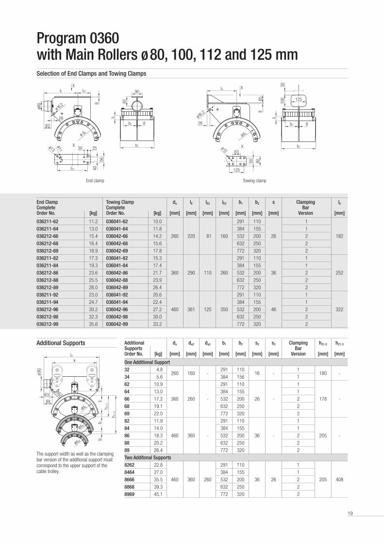
Program 0360 with Main Rollers ø 80, 100, 112 and 125 mmSelection of End Clamps and Towing Clamps
Additional da da2 da3 b1 b2 s2 s3 Clamping Bar
Version
hZ1-2 hZ1-3 Supports Order No.
[kg]
[mm]
[mm]
[mm]
[mm]
[mm]
[mm]
[mm]
[mm]
[mm]
One Additional Support32 4 .8
260 160 -291 110
16 -1
180 -34 5 .6 384 156 1
62 10 .9
360 260 -
291 110
26 -
1
178 -
64 13 .0 384 155 1
66 17 .2 532 200 2
68 19 .1 632 250 2
69 22 .0 772 320 2
82 11 .9
460 360 -
291 110
36 -
1
205 -
84 14 .0 384 155 1
86 18 .3 532 200 2
88 20 .2 632 250 2
89 26 .4 772 320 2
Two Additonal Supports8262 22 .8
460 360 260
291 110
36 26
1
205 408
8464 27 .0 384 155 1
8666 35 .5 532 200 2
8868 39 .3 632 250 2
8969 45 .1 772 320 2
The support width as well as the clamping bar version of the additional support must correspond to the upper support of the cable trolley .
End clamp Towing clamp
Additional Supports
End Clamp Complete
Towing Clamp Complete
da lE lE2 lE3 b1 b2 s Clamping Bar
Version
lk
Order No. [kg] Order No. [kg] [mm] [mm] [mm] [mm] [mm] [mm] [mm] [mm]
036211-62 11 .2 036041-62 10 .0
260 220 81 160
291 110
26
1
182
036211-64 13 .0 036041-64 11 .8 384 155 1
036212-66 15 .4 036042-66 14 .2 532 200 2
036212-68 16 .4 036042-68 15 .6 632 250 2
036212-69 18 .9 036042-69 17 .8 772 320 2
036211-82 17 .3 036041-82 15 .3
360 290 110 260
291 110
36
1
252
036211-84 19 .3 036041-84 17 .4 384 155 1
036212-86 23 .6 036042-86 21 .7 532 200 2
036212-88 25 .5 036042-88 23 .9 632 250 2
036212-89 28 .0 036042-89 26 .4 772 320 2
036211-92 23 .0 036041-92 20 .6
460 361 125 350
291 110
46
1
322
036211-94 24 .7 036041-94 22 .4 384 155 1
036212-96 30 .2 036042-96 27 .2 532 200 2
036212-98 32 .3 036042-98 30 .0 632 250 2
036212-99 35 .6 036042-99 33 .2 772 320 2
Ik
s
100
30
865
8050
b1
125
63
26 b2 8
125
ø da
ø16.2
ø 13
X
X
IE
s
IE2 90
8b2
IE3
63
ø13
ø11
ø da
X2530
b1
ø 16.2ø8
0
56
408 82
26
X
øda3
ø16.2
h z1-
2
lwk
ø 80
h z1-
3
s 3s 2
s
63
89
øda2
øda

20
Program 0360 with Main Rollers ø 80 and 100 mmSelection of Running Gear
Note/design• Main roller ø 80 mm: anti-lift rollers ø 50 mm and horizontal guide rollers ø 50 mm made of steel .• Main roller ø 100 mm: anti-lift rollers ø 50 mm and horizontal guide rollers ø 63 mm made of steel .• Other materials of the horizontal guide rollers, e .g . Polyurethane on request .• The rollers are equipped with precision ball bearings and additional sealing disks (2RS1) . The ball bearings are lifetime lubricated .• Running gear for other I-beam types or beam sizes on request .
Running Gear Order No.
Main Roller Weight approx.
[kg]
Preference Range I-beamsød
[mm]Material Bandage
Parallel Flange
I-beam Code
Tapered Flange
I-beam Code
Typ H mit zylindrischen Haupttragrollen
511 80 Steel 8 .3 --
--
INP 140INP 160
00140016551 80 Polyurethane 7 .7
611 100 Steel 12 .3 ---
---
INP 140INP 160INP 180
001400160018651 100 Polyurethane 11 .8
Typ HG mit zylindrischen Haupttragrollen und Gegendruckrollen
512 80 Steel 9 .5 --
--
INP 140INP 160
00140016552 80 Polyurethane 8 .1
612 100 Steel 13 .8 ---
---
INP 140INP 160INP 180
001400160018652 100 Polyurethane 13 .3
Typ HF mit zylindrischen Haupttragrollen und horizontalen Führungsrollen
513 80 Steel 9 .7 IPE 140IPE 160IPE 180IPE 200
0114011601180120
INP 140INP 160INP 180INP 200
0014001600180020557 80 Polyurethane 8 .3
613 100 Steel 13 .3 IPE 160IPE 180IPE 200IPE 220IPE 240
01160118012001220124
INP 160INP 180INP 200INP 220INP 240
00160018002000220024657 100 Polyurethane 12 .8
Typ HFG mit zylindrischen Haupttragrollenhorizontalen Führungsrollen und Gegendruckrollen
514 80 Steel 9 .8 IPE 140IPE 160IPE 180IPE 200
0114011601180120
INP 140INP 160INP 180INP 200
0014001600180020558 80 Polyurethane 9 .3
614 100 Steel 14 .3 IPE 160IPE 180IPE 200IPE 220IPE 240
01160118012001220124
INP 160INP 180INP 200INP 220INP 240
00160018002000220024658 100 Polyurethane 13,8
Typ S mit Spurkranz- Haupttragrollen
531 80 Steel 9 .9
IPE 140IPE 160IPE 180IPE 200
0114011601180120
INP 140INP 160INP 180INP 200
0014001600180020
631 100 Steel 16 .0
IPE 160IPE 180IPE 200IPE 220IPE 240
01160118012001220124
INP 160INP 180INP 200INP 220INP 240
00160018002000220024
Typ SG mit Spurkranz- Haupttragrollen und Gegendruckrollen
532 80 Steel 11 .3
IPE 140IPE 160IPE 180IPE 200
0114011601180120
INP 140INP 160INP 180INP 200
0014001600180020
632 100 Steel 17 .3
IPE 160IPE 180IPE 200IPE 220IPE 240
01160118012001220124
INP 160INP 180INP 200INP 220INP 240
00160018002000220024

21
Program 0360 with Main Rollers ø 112 and 125 mmSelection of Running Gear
Note/design• The running gear of the towing trolley must always be equipped with anti-lift rollers .• Main roller ø 112 mm: anti-lift rollers ø 50 mm and horizontal guide rollers ø 63 mm made of steel• Main roller ø 125 mm: anti-lift rollers ø 63 mm and horizontal guide rollers ø 80 mm made of steel• Other materials of the horizontal guide rollers, e .g . Polyurethane on request .• The rollers are equipped with precision ball bearings and additional sealing disks (2RS1) . The ball bearings are lifetime lubricated .• Running gear for other I-beam types or beam sizes on request .
Running Gear Order No.
Main Roller Weight approx.
[kg]
Preference Range I-beamsd
[mm]Material Bandage
Parallel Flange
I-beam Code
Tapered Flange
I-beam Code
Typ H mit zylindrischen Haupttragrollen
751 112 Polyurethane 14 .4---
---
INP 180INP 200INP 220
001800200022
811 125 Steel 21 .0 --
--
INP 200INP 220
00200022851 125 Polyurethane 18 .2
Typ HG mit zylindrischen Haupttragrollen und Gegendruckrollen
752 112 Polyurethane 15 .4 --
--
INP 180INP 200INP 220
001800200022
812 125 Steel 22 .0 --
--
INP 200INP 220
00200022852 125 Polyurethane 19 .2
Typ HF mit zylindrischen Haupttragrollen und horizontalen Führungsrollen
757 112 Polyurethane 14 .4IPE 160IPE 180IPE 200
011601180120
INP 180INP 200INP 220
001800200022
813 125 Steel 23 .0 IPE 180IPE 200
01180120
INP 200INP 220
00200022857 125 Polyurethane 18 .7
Typ HFG mit zylindrischen Haupttragrollenhorizontalen Führungsrollen und Gegendruckrollen
758 112 Polyurethane 15 .4IPE 160IPE 180IPE 200
011601180120
INP 180INP 200INP 220
001800200022
814 125 Steel 25 .2IPE 180IPE 200
01180120
INP 200INP 220
00200022858 125 Polyurethane 18 .7

23
Ordering Example Order No. 036423-83 - 758 - 0018
A cable trolley underpart with the following dimensions shall be used:• Support diameter: da = 360 mm • Clamping width: b2 = 125 mm; • Clamping height: s = 36 mm• Order No.: 036423-83 (chosen from catalog page 24)
The following running gear has been chosen:Type HFG, cylindrical main rollers ø 112 mm with Polyurethane bandage• with horizontal guide rollers made of steel• with anti-lift rollers made of steelOrder No. 758 (chosen from catalog page 25)
The following track beam has been chosen:• INP 180• I-beam code: 0018 (chosen from catalog page 25)
The Order No. of the appropriate towing trolley is the running gear must always be equipped with anti-lift rollers: 036433-83-758-0018
The Order No. of the appropriate towing trolley for the connection to the catenary trolley is:: 036453-83-758-0018
The Order No. of the appropriate end clamp is: 036413-83
As an alternative to the towing trolley a towing clamp can be used .The Order No. of the appropriate towing clamp is: 036443-83
For calculation and selection please refer to our Engineering Guidelines for Festoon Systems KAT0300-0101
Program 0364 with Main Rollers ø 100 and 112 mmSingle Layer Cable Trolley with Round Cables with a Load Capacity up to 125 kg
Technical detailsCable Supports bolted to the center plate,
lateral-loading and reinforced
Buffers double-sided round buffer
Max . Travel Speed 1) 180 m/min
Max . Load Capacity 1) 125 kg
Cable Trolley Underpart and Running Gear hot-dip galvanized steel
Fasteners stainless steel
Temperature Range -30°C to + 50°C
1) depending on roller size/ roller material
b2b2
b1
70
V-clamping (divided)
For STS container cranes with rope-driven main trolley and catenary trolley .A connection between catenary trolley and festoon system by an additional towing trolley is required .

24
Cable Trolley Underpart1)
Towing Trolley Underpart1)
da
[mm]
lw
[mm]
b1
[mm]
b2
[mm]
s
[mm]
k
[mm]
ha
[mm]
hw
[mm]
lM
[mm]
lMF
[mm]Order No. [kg] Order No. [kg]
036423-83 21 036433-83 25
360 533
384 125
36 355 320 500 302 288036423-86 25 036433-86 29 532 200
036423-88 29 036433-88 31 632 250
036423-93 24 036433-93 26
460 653
384 125
46 475 220 450 372 358036423-96 30 036433-96 31 532 200
036423-98 45 036433-98 46 632 250
Program 0364 with Main Rollers ø 100 and 112 mmSelection of Cable Trolleys, Towing Trolleys and Towing Trolleys for Catenary Trolley
Cable trolley Towing trolley
Towing trolley for catenary trolley
1) without running gear
Towing Trolley Underpart for Catenary Trolley without Running Gear
da
[mm]
lc
[mm]
b1
[mm]
b2
[mm]
s
[mm]
k
[mm]
ha
[mm]
hw
[mm]Order No. [kg]
036453-83 21
360 533
384 125
36 355 320 500036453-86 25 532 200
036453-88 29 632 250
036453-93 34
460 653
384 125
46 475 220 450036453-96 38 532 200
036453-98 46 632 250
89
ø 80
ø da
~h w
~h a
63
b2 b2
8
klw
s
b1
ø 16.220°
89
ø 80 12
0
63
b2 b2
8
lM
s
b1
ø 16.2
lMF
140
ø da
3090
20°
89
ø 80
ø da
120
~h a
63
b2 b2
8
klC
s
b1
ø 16.220°
88
~140
~h w
Note/design• The table only refers to the cable trolley or towing trolley underpart, the running gear must be selected and added . See page 25 of this catalog .• Additional supports are not available in this program .

25
Cable Trolley Underpart1)
Towing Trolley Underpart1)
da
[mm]
lw
[mm]
b1
[mm]
b2
[mm]
s
[mm]
k
[mm]
ha
[mm]
hw
[mm]
lM
[mm]
lMF
[mm]Order No. [kg] Order No. [kg]
036423-83 21 036433-83 25
360 533
384 125
36 355 320 500 302 288036423-86 25 036433-86 29 532 200
036423-88 29 036433-88 31 632 250
036423-93 24 036433-93 26
460 653
384 125
46 475 220 450 372 358036423-96 30 036433-96 31 532 200
036423-98 45 036433-98 46 632 250
Running Gear Order No.
Main Roller Weight approx.
[kg]
Preference Range I-beamsød
[mm]Material Bandage
Parallel Flange
I-beam Code
Tapered Flange
I-beam Code
Type HFG with cylindrical main rollers, horizontal guide rollers and anti-lift rollers
658 100 Polyurethane 13 .8
IPE 160IPE 180IPE 200IPE 220
0116011801200122
INP 160INP 180INP 200INP 220
0016001800200022
758 112 Polyurethane 15 .4
IPE 160IPE 180IPE 200IPE 220
0116011801200122
INP 180INP 200INP 220
-
001800200022
-
Program 0364 with Main Rollers ø 100 and 112 mmSelection of End Clamps and Towing Clamps
End clamp Towing clamp
End Clamp Complete
Towing Clamp Complete
da
[mm]
lE
[mm]
lE2
[mm]
lE3
[mm]
b1
[mm]
b2
[mm]
s
[mm]
lk
[mm]Order No. [kg] Order No. [kg]
036413-83 21 .0 036443-83 21 .0
360 290 146 260
384 125
36 282036413-86 25 .0 036443-86 25 .0 532 200
036413-88 36 .0 036443-88 36 .0 632 250
036413-93 20 .0 036443-93 22 .0
460 361 208 350
384 125
46 352036413-96 24 .0 036443-96 25 .0 532 200
036413-98 44 .5 036443-98 44 .0 632 250
Selection of Running Gear
ø da
90
82
b2 b2
IE3
b1
IE IE2
89
63ø 16
.2
840 56
ø 80
s
2530
ø 13 ø 11
X
X
8
20°
lk
100
ø da
56
125
b2 b2
b1
8
63
125
30
s
658
ø 16.2
80
50ø 13
Note/design• Main roller ø 100 mm: anti-lift rollers ø 50 mm and horizontal guide rollers ø 63 mm made of steel• Main roller ø 112 mm: anti-lift rollers ø 50 mm and horizontal guide rollers ø 63 mm made of steel• Other materials of the horizontal guide rollers, e .g . Polyurethane on request .• The rollers are equipped with precision ball bearings and additional sealing disks (2RS1) . The ball bearings are lifetime lubricated .• Running gear for other I-beam types or beam sizes on request .

26
Accessories for Program 0350, 0360 and 0364Towing Ropes
Order No. ød
[mm]
LSch Material Version Program for Main Rollers ød
[mm]Rope Shackle Fasteners
031962
10 42 Galvanized steel PVC-coated
Galvanized steel
Galvanized steel/ aluminum
10350 50, 63, 80, 100
0360 50, 63
031963 20360 80, 100, 112, 125
0364 100, 112
Damping Devices
Technical details• Shock cord: rubber with plastic plait• Console: hot-dip galvanized steel• Fasteners: stainless steel
Order No. Number of Shock Cords
ød
[mm]
Program for Main Rollersød
[mm]
031966 2 14 0350 50, 63, 80, 100
031970-2 2 20 0350 50, 63, 80, 100
031966 2 14 0360 50, 63
031970-2 2 20 0360 50, 63
031976-2 2 20 0360, 0364 80, 100, 112, 125
031977-2 4 20 0360, 0364 80, 100, 112, 125
031978-2 6 20 0360, 0364 80, 100, 112, 125
Notes• We recommend the installation of damping devices
for high speed and/or short cable loops• For the calculation of the length please refer to our
Engineering Guidelines• In case of order please state the length of the
respective shock cords• Number and diameter are defined by weight load,
cable loop and speed
Notes• We recommend the installation of towing ropes for a speed from 50 m/min or a travel distance > 30 m• The towing ropes are PVC-coated for a better protection against corrosion and to prevent the cables from damage• For the calculation of the lengths please refer to our Engineering Guidelines for Festoon Systems KAT0300-0101• In case of order please state the lengths LZug of the respective towing ropes
Version 1 Version 2
031965/18/10 48 Stainless Steel
PVC-coated Stainless Steel Stainless Steel Aluminum - Seawater resistant
1 0350 50, 63, 80, 1000360 50,63
031965/2 2 0360 80, 100, 112, 1250364 100, 112
LSch
9
LSch LZug
ø d
ø 12
LSch
17
LSch LZug
ø d
ø 16
ød
LGum

27
Accessories for Program 0350, 0360 and 0364Cable Organizers for Cable Loops
Order No. ød[mm]
b [mm]
S [mm]
Material Fasteners Weight[kg]
031942-0300x15 300 30 20 Rubber - 0 .59
NoteFor cable loops > 4 m, the cable organizer in addition to the flat and round cable clamps prevents an expansion of the cables at the lower section of the cable loop .
Additional Clamping Pieces for Round Cable Clamps
NoteDifferences in diameter between adjacent cables of more than 15 mm require additional clamping pieces for a tight clamping .
Version 1 Version 2
73
90
53
20
85 20
110
65
s
ød
b
Order No. For Systems with Main Roller Diameter ød
[mm]
Support diameter øda
[mm]
Version Material Weight [kg]
031899-053x020/514 50 and 63 260 and 360 1Rubber
0 .06
031899-065x020/514 80, 100, 112 and 125 360 and 460 2 0 .08
28
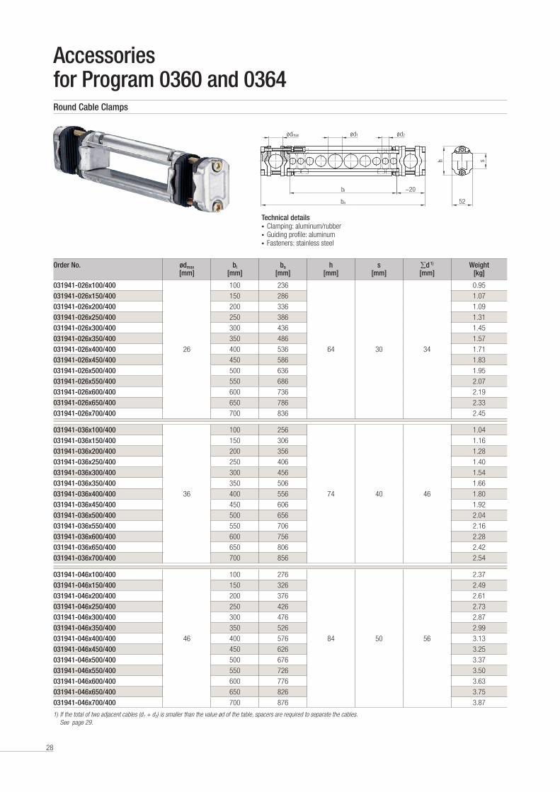
Technical details• Clamping: aluminum/rubber• Guiding profile: aluminum• Fasteners: stainless steel
ø d1ø dmax
bi
ba
~20
52
ø d2
h s
Accessories for Program 0360 and 0364Round Cable Clamps
Order No. ødmax [mm]
bi [mm]
ba [mm]
h [mm]
s [mm]
∑d 1) [mm]
Weight [kg]
031941-026x100/400
26
100 236
64 30 34
0 .95
031941-026x150/400 150 286 1 .07
031941-026x200/400 200 336 1 .09
031941-026x250/400 250 386 1 .31
031941-026x300/400 300 436 1 .45
031941-026x350/400 350 486 1 .57
031941-026x400/400 400 536 1 .71
031941-026x450/400 450 586 1 .83
031941-026x500/400 500 636 1 .95
031941-026x550/400 550 686 2 .07
031941-026x600/400 600 736 2 .19
031941-026x650/400 650 786 2 .33
031941-026x700/400 700 836 2 .45
031941-036x100/400
36
100 256
74 40 46
1 .04
031941-036x150/400 150 306 1 .16
031941-036x200/400 200 356 1 .28
031941-036x250/400 250 406 1 .40
031941-036x300/400 300 456 1 .54
031941-036x350/400 350 506 1 .66
031941-036x400/400 400 556 1 .80
031941-036x450/400 450 606 1 .92
031941-036x500/400 500 656 2 .04
031941-036x550/400 550 706 2 .16
031941-036x600/400 600 756 2 .28
031941-036x650/400 650 806 2 .42
031941-036x700/400 700 856 2 .54
031941-046x100/400
46
100 276
84 50 56
2 .37
031941-046x150/400 150 326 2 .49
031941-046x200/400 200 376 2 .61
031941-046x250/400 250 426 2 .73
031941-046x300/400 300 476 2 .87
031941-046x350/400 350 526 2 .99
031941-046x400/400 400 576 3 .13
031941-046x450/400 450 626 3 .25
031941-046x500/400 500 676 3 .37
031941-046x550/400 550 726 3 .50
031941-046x600/400 600 776 3 .63
031941-046x650/400 650 826 3 .75
031941-046x700/400 700 876 3 .87
1) If the total of two adjacent cables (d1 + d2) is smaller than the value ød of the table, spacers are required to separate the cables. See page 29.

29
Small versionBroad version
bi
s 1
ba
36
s 2
h max
.
t
s
b
40
48
t
s
b
Accessories for Program 0350, 0360 and 0364
Flat Cable Clamps
Order No. bi
[mm]ba
[mm]s1 + s2
[mm]s1min. [mm]
hmax. [mm]
Weight [kg]
031953-084x045/400
84 120
45
+2 .5 5
80 0 .18
031953-084x055/400 55 90 0 .19
031953-084x065/400 65 100 0 .21
031953-084x075/400 75 110 0 .22
031953-084x085/400 85 120 0 .23
031953-136x045/400
136 172
45
+2 .5 5
80 0 .24
031953-136x055/400 55 90 0 .25
031953-136x065/400 65 100 0 .27
031953-136x075/400 75 110 0 .28
031953-136x085/400 85 120 0 .29
Notes• By changing the distance tubes from window s2 to window
s1,the flat cable clamp can be adjusted to fit the cable pa-ckage .
• The window with the dimension s2 must be adjusted to an appropriate dimension, so that the cables can move with sufficient clearance (> 15 mm) .
Spacers
Order No. s [mm]
t [mm]
b [mm]
Appropriate Cable Clamp
Material Version Weight [kg]
031946-26 25 4 18 031941-026x…
Plastic Small
0 .010
031946-36 35 5 19 031941-036x… 0 .015
031946-46 45 6 20 031941-046x… 0 .025
031947-26 25 4 26 031941-026x…
Plastic Broad
0 .015
031947-36 35 5 27 031941-036x… 0 .020
031947-46 45 6 28 031941-046x… 0 .025
NotesThe above drawings are examples for illustration only .Small version for cables with outer diameter smaller 14 mm and larger 22 mm .Broad version for cables with outer diameter larger 14 mm and smaller 22 mm .

30
s 2s 1
ba
56bi 36
h max
s 2
s 1
ba
16bi 36
h max
bi
Accessories for Program 0350
Order No. bi
[mm]
ba
[mm]
s1 + s2 [mm]
s1
min. [mm]
hmax
[mm]
Weight
[kg]
031954-084x045/400
84 257
45
+2 .5 5
80 0 .42
031954-084x055/400 55 90 0 .44
031954-084x065/400 65 100 0 .46
031954-084x075/400 75 110 0 .48
031954-084x085/400 85 120 0 .52
031954-136x045/400
136 364
45
+2 .5 5
80 0 .53
031954-136x055/400 55 90 0 .57
031954-136x065/400 65 100 0 .60
031954-136x075/400 75 110 0 .63
031954-103x085/400 85 120 0 .66
031954-184x045/400
184 460
45
+2 .5 5
80 0 .85
031954-184x055/400 55 90 0 .88
031954-184x065/400 65 100 0 .91
031954-184x075/400 75 110 0 .94
031954-184x085/400 85 120 0 .97
Flat Cable Clamps
Order No. bi
[mm]
ba
[mm]
s1 + s2
[mm]
s1
min. [mm]
hmax
[mm]
Weight
[kg]
031955-084x045/400
84 220
45
+2 .5 5
80 0 .43
031955-084x055/400 55 90 0 .44
031955-084x065/400 65 100 0 .46
031955-084x075/400 75 110 0 .48
031955-084x085/400 85 120 0 .49
031955-103x045/400
103 258
45
+2 .5 5
80 0 .46
031955-103x055/400 55 90 0 .47
031955-103x065/400 65 100 0 .49
031955-103x075/400 75 110 0 .51
031955-103x085/400 85 120 0 .52

31
ød ød
ød
ød
Wear Parts for Program 0350, 0360 and 0364Replacement Rollers for Running Gear
Flanged main roller Main roller cylindrical Horizontal guide roller Anti-lift roller
Replacement Rollers for Running Gear ø 50 mm and ø 63 mm
Running Gear Type
Order No. Rollers Weight approx.
[kg]
For I-beamsDescription ød
[mm]Material Bandage
Parallel Flange
Tapered Flange
H
HG
030102-050.1
Main roller cylindrical
50 Steel 0 .28- 120
030113-050.1 50 Polyurethane 0 .19
030102-063.1 63 Steel 0 .30
- 140030113-063.1 63 Polyurethane 0 .22
030108-040.1 Anti-lift roller 40 Steel 0 .13
HF
HFG
030102-050.3
Main roller cylindrical
50 Steel 0 .27100 - 180 120 - 180
030113-050.2 50 Polyurethane 0 .16
030102-063.3 63 Steel 0 .48120 - 200 120 - 180
030113-063.2 63 Polyurethane 0 .21
030105-040 Horizontal guide roller 40 Steel 0 .21120 - 200 120 - 180
030108-040.2 Anti-lift roller 40 Steel 0 .13
S
SG
030101-050 Flanged main roller
50 Steel 0 .42 100 - 180120 - 180
030101-063 63 Steel 0 .74 120 - 200
030108-040.1 Anti-lift roller 40 Steel 0 .13 100 - 200 120 - 180
Replacement Rollers for Running Gear ø 80 mm and ø 100 mm
Running Gear Type
Order No. Rollers Weight approx.
[kg]
For I-beamsDescription ød
[mm]Material Bandage
Parallel Flange
Tapered Flange
H
HG
030102-080.1
Main roller cylindrical
80 Steel 0 .65- 140 - 160
030113-080.1 80 Polyurethane 0 .41
030102-100.1 100 Steel 1 .13- 180
030113-100.3 100 Polyurethane 0 .68
030108-050.1 Anti-lift roller 50 Steel 0 .31 - 140 - 180
HF
HFG
030102-080.2 Main roller cylindrical
80 Steel 0 .64
140 - 200 140 - 200030113-080.2 80 Polyurethane 0 .40
030105-050.1 Horizontal guide roller 50 Steel 0 .36
030102-100.2 Main roller cylindrical
100 Steel 1 .10
160 - 240 160 - 240030113-100.2 100 Polyurethane 0 .62
030105-063.1 Horizontal guide roller 63 Steel 0 .63
030108-050.1 Anti-lift roller 50 Steel 0 .31 140 - 240 140 - 240
S
SG
030101-080 Flanged main roller
80 Steel 1 .27 140 - 200 140 - 200
030101-100 100 Steel 2 .25 160 - 240 160 - 240
030108-050.1 Anti-lift roller 50 Steel 0 .31 140 - 240 140 - 240

32
ød ød
ød
ød
Wear Parts for Program 0350, 0360 and 0364Replacement Rollers for Running Gear
Replacement Rollers for Running Gear ø 112 mm and ø 125 mm
Running Gear Type
Order No. Rollers Approx. Weight
[kg]
For I-beamsDescription ød
[mm]Material Bandage
Parallel Flange
Tapered Flange
H
HG
030113-112.1Main roller cylindrical 112 Polyurethane 1 .00
- 180
030113-112.2 - 200 - 220
030108-050.1 Anti-lift roller 50 Steel 0 .27 - 180 - 220
030102-125.1 Main roller cylindrical 125
Steel 3 .00
- 200 - 220030113-125.1 Polyurethane 1 .11
030108-063.1 Anti-lift roller 63 Steel 0 .50
030113-112.2 Main roller cylindrical 112 Polyurethane 1 .00
160 - 200 180 - 220030105-063.1 Horizontal guide roller 63 Steel 0 .63
030108-050.1 Anti-lift roller 50 Steel 0 .50
030102-125.2 Main roller cylindrical 125
Steel 3 .00
180 - 200 200 - 220030113-125.2 Polyurethane 1 .20
030105-080.1 Horizontal guide roller 80 Steel 0 .82
030108-063.1 Anti-lift roller 63 Steel 0 .50
Shock Cords
Technical details• Shock cord: rubber with plastic plait• Fasteners: stainless steel/hot-dip galvanized steel
NoteIn case of order please state the lengths LGum of the respective shock cords .
Order No. ød [mm]
Weight [kg/m]
031987 14 0 .2
031989-2 20 0 .4
Flanged main roller Main roller cylindrical Horizontal guide roller Anti-lift roller
ød
LGum
HF HFG

33
63
ø80
40
M10
100
4555
40
M8
150
60
70
60
M10
Wear Parts for Program 0350, 0360 and 0364Rectangular Buffer
Round Buffer
Program 0350, Main Rollers ø 50 mm up to ø 100 mm
Order No. Shore Hardness A
Material Weight [kg]
Component
031980-045x100/517 70Rubber
0 .5 Cable trolley
031980-060x150/617 70 0 .7 End clamp
Notes• Rollers, shock cords and buffers are maintenance items and must be inspected and/or replaced regularly .• Please follow our maintenance instructions .
Order No. Shore Hardness A
Material Weight
[kg]
Program For Main Roller Diameter d [mm]
031980-080x063/514 40Rubber
0 .5 0360 80 - 125
031980-080x063/517 70 0 .5 0364 100 - 112
Rectangular buffer for cable trolleys Rectangular buffer for end clamps
Program 0360, Main Rollers ø 50 mm up to ø 63 mm
Order No. Shore Hardness A
Material Weight [kg]
Component
031980-045x100/517 70Rubber
0 .5 Cable trolley
031980-060x150/617 70 0 .7 End clamp
Notes• Rollers, shock cords and buffers are maintenance items and must be inspected and/or replaced regularly .• Please follow our maintenance instructions .

34
Spare Parts for Program 0350, 0360 and 0364Cable Supports including Clamping Bar
Notes• Spare parts are parts that are not subject to natural wear and are usually damaged by outside influence .• In the case that a spare item is required, please provide the system component (e .g . cable trolley) for which the replacement
part is required together with the item's designation .
Clamping Bars (Complete)
Side Shields (Complete)
Running Gears (Complete)
Consisting of:• 2 x cable support• 2 x clamping bar• Fasteners
Consisting of:• C-Rail• Clamping rubber• Fasteners
Consisting of:• Side shield• Rollers assembled
Consisting of:• 4 x side shields (complete)• Distance pieces• Fasteners
Order No. for Main Rollers ød [mm]
Program
039002- 50/63 0360
039003- 80/100/112/125 0360
039004- 100/112 0364
Order No. Program Cable type
039010- 0360 round
039012- 0350 flat
Order No. Program Running Gears Type
Main RollerMaterialBinding
039051- 0350/0360 S/SG Steel
039052- 0350/0360 H/HG/HF/HFG Steel
039055- 0350/0360 H/HG/HF/HFG Polyurethane

35
Your Applications – our Solutions
Festoon Systems from Conductix-Wampfler represent only one of the many solutions made possible by the broad spectrum of
Conductix-Wampfler components for the transport of energy, data and fluid media . The solutions we deliver for your applications
are based on your specific requirements . In many cases, a combination of several different Conductix-Wampfler systems can prove
advantageous . You can count on all of Conductix-Wampfler’s Business Units for hands-on engineering support - coupled with the
perfect solution to meet your energy management and control needs .
Jib boom
Complete with tool transporters, reels,
or an entire media supply system –
here, safety and flexibility are key to
the completion of difficult tasks .
Conductor rails
Whether they‘re enclosed conductor
rails or expandable single-pole
systems, the proven conductor rails
by Conductix-Wampfler reliably move
people and material .
Non-insulated conductor rails
Extremely robust, non-insulated
conductor rails with copper heads or
stainless steel surfaces provide the
ideal basis for rough applications, for
example in steel mills or shipyards .
Cable reels
Motorized reels and spring reels by
Conductix-Wampfler hold their own
wherever energy, data and media
have to cover the most diverse
distances within a short amount of
time - in all directions, fast and safe .
Festoon systems
It‘s hard to imagine Conductix-
Wampfler cable trolleys not being
used in virtually every industrial
application . They‘re reliable and
robust and available in an enormous
variety of dimensions and designs .
Conveyor systems
Whether manual, semiautomatic
or with Power & Free – flexibility
is achieved with full customization
concerning layout and location .
Reels, retractors and balancers
Whether for hoses or cables, as
classical reels or high-precision
positioning aids for tools, our range
of reels and spring balancers take the
load off your shoulders .
Inductive Power Transfer IPT®
The no-contact system for transferring
energy and data . For all tasks that
depend on high speeds and absolute
resistance to wear .
Slip ring assemblies
Whenever things are really “moving
in circles“, the proven slip ring
assemblies by Conductix-Wampfler
ensure the flawless transfer of energy
and data . Here, everything revolves
around flexibility and reliability!
Energy guiding chains
The “Jack of all trades“ when it comes
to transferring energy, data, air and fluid
hoses . With their wide range, these
energy guiding chains are the ideal
solution for many industrial applications .

www.conductix.com
KAT0
350-
0001
f-E
© C
ondu
ctix-
Wam
pfler
| 20
17 |
subj
ect t
o te
chni
cal m
odifi
catio
ns w
ithou
t prio
r not
ice Conductix-Wampfler
has just one critical mission:
To provide you with energy and
data transmission systems that
will keep your operations up
and running 24/7/365 .
To contact your nearest
sales office, please refer to:
www.conductix.com/contact-search