kam owd water cut meter · * the kam® owd® must be installed in accordance with api mpms chapter...
TRANSCRIPT

KAM® OWD® WATER CUT METER PTB 08 ATEX 1026
TEL +1 713 784 0000 FAX +1 713 784 0001
Email [email protected] KAM CONTROLS, INC.
3939 Ann Arbor Drive Houston, Texas 77063 USA
www.KAM.com
User ManualOWDMANUAL 1114
An ISO 9001 certified company

OWDMANUAL 1114 KAM CONTROLS, INC.1
TA B L E O F C O N T E N T S
SECTION TITLE PAGE 1 Introduction 2 •AvailableModelsandMountingOptions 2 •TheoryofOperation 3 •Features 3 •Applications 3
2 Specifications 4 •Specifications 4 •DimensionalDrawings 5
3 Installation 10 •InstallationFlowRequirements 10 •LACTunitinstallation 11 •GeneralDo'sandDon't's 12 •MainLine 13 •FastLoop 16 •Wiring 17 4 OWD Operation 21 •HyperterminalSoftware 21 •Calibration 25 •ChangingtheRange 26 •ModbusInterface 26
5 Maintenance 27 •Cleaning/Inspection 27 •Troubleshooting 27 •AntennaReplacement 28
APPENDIX A: ModbusRegisters 35
CAUTION:
WheninstallingtheOWD®sensorinapipelinecontainingpetroleumproducts,petrochemicals,wastewaterswiththepresenceofpressure&temperature,andhigh-pressuresteamrefertothePipelineOperators’"Health,SafetyandEnvironmentalPolicyProcedures"toensuresafeinstallation.
KAMCONTROLS,INC.reservestherighttomakechangestothisdocumentwithoutnotice.
OWDMANUAL 1114 KAM CONTROLS, INC.2
P
I N T R O D U C T I O N
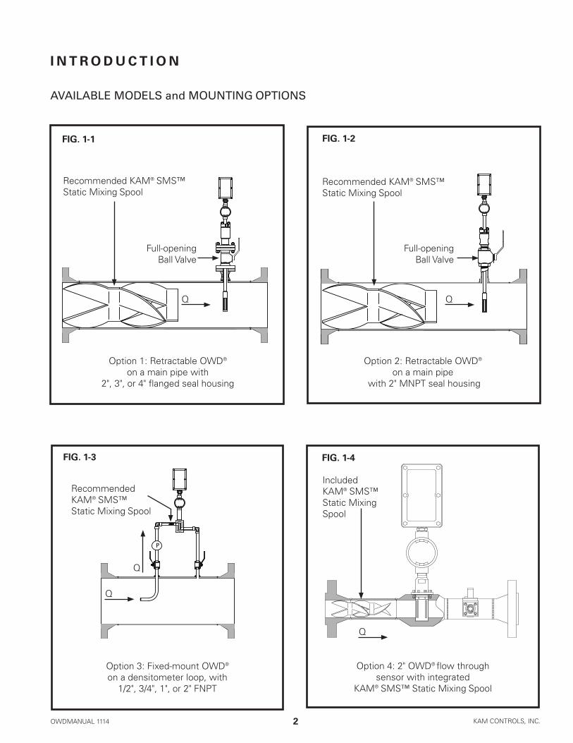
AVAILABLE MODELS and MOUNTING OPTIONS
FIG. 1-1 FIG. 1-2
FIG. 1-3
Option3:Fixed-mountOWD® onadensitometerloop,with1/2",3/4",1",or2"FNPT
Option 2: Retractable OWD® on a main pipe
with2"MNPTsealhousing
Option 1: Retractable OWD® onamainpipewith
2",3",or4"flangedsealhousing
Full-openingBall Valve
Full-openingBall Valve
Q
Q
Q
Q
Q
FIG. 1-4
Option4:2"OWD® flowthroughsensorwithintegrated
KAM®SMS™StaticMixingSpool
Recommended KAM® SMS™ StaticMixingSpool
Recommended KAM® SMS™ StaticMixingSpool
Recommended KAM® SMS™ StaticMixingSpool
Included KAM® SMS™ StaticMixingSpool

OWDMANUAL 1114 KAM CONTROLS, INC.3
I N T R O D U C T I O N C O N T I N U E D
Rugged,easytouseandextremelyaccurate,theKAM® OWD®OilWaterDetectoristheidealinstrumentforcontinu-ouslymonitoringwaterconcentrationinyourpipeline.ItisdesignedinaccordancewithAPI,ASTM,ISO,EI,UL,andDINstandardsamongstothers.Especiallyvitalinproductionmanagement,theOWD® sensor lets you maximize oil productionversusproducedwater.ThesimplicityofdesignandqualityofengineeringemployedintheOWD® sensor meantherearenomovingparts.Patentedmicrowavesensorsmeasuretheconductivity,dielectric,andboththerealandimaginarypartofpermittivityofthefluidwithanextremelyhighdegreeofaccuracy,andmeasurementisfullyautomaticwithouttheneedforoperatorinterventionorsupervision.TheoutputsignalcanbesenttoFlowComputers,SCADA,PLC’sortoaCentralControlRoomforloggingordisplayonchartrecordersormonitors.
TheKAM® OWD®sensoralsousesinternalreferencestoautocalibratefordriftcausedbytemperaturechangesoftheelectronics,theagingoftheelectronicscomponents,fluidpressure,andfluidtemperature.
TheKAM® OWD®flowthroughmodelcanbeusedinananalyzer/densitometerloop,forprocessoptimizationwhereanaccuratedeterminationofwaterconcentrationisimportant,anditisvitaltooptimizingthedesalinizationprocess.Placedonthedesaltersampleline,oroneachsampleline,theKAM® OWD®flowthroughmodelprovidesreal-timeinformationaboutyourdesalterperformance.
Toensurethehighestdegreeofaccuracy,theflowmustbehomogenous.InstalledupstreamofyourOWD® sensor,thepatentedKAM®SMP™StaticMixingPlateorKAM®SMS™StaticMixingSpoolcreateafullyhomogenousmixtureinyourpipeline.Inlowvelocitysituations,theuseofaKAMMLMeasurementLoopmayberequiredinordertocreateahomogenousflowformeasurement.Propercalibration,alsokeytocompleteaccuracy,canbeachievedinthefieldwiththeKAM®PKFPortableKarlFischerMoistureAnalyzer.
Becauseitcanbeinsertedintoyourpipeortankthrougha2",3",or4"hottap,theOWD®sensorhelpsyouavoidcostlydrainage,theneedforabypassloop,orhavingtocutasectioninthepipe.Allwettedpartsaremachinedfrom316stainlesssteel.Shaftlengthsfrom1to3feetareavailablewithoff-the-shelflengthscomingin12",24",and36".Metricandcustomlengthsareavailable.
Range(waterinoil) 0-1% 0–5% 0–10% 0–20% 0–40% 0–100%Accuracy(atlistedrange)0.01% 0.05% 0.10% 0.20% 0.40% 1.00%
TABLE 1-5 MEASUREMENTCAPABILITIES:CALIBRATEDRANGEANDACCURACIES
NOTE:TheKAMOWDcanbecalibratedtoanyrangebetween0-1%and0-100%.
THEORY OF OPERATION

OWDMANUAL 1114 KAM CONTROLS, INC.4
S P E C I F I C AT I O N S
Media: Crudeoil,refinedproductsandchemicals
Material: Wettedparts-316stainlesssteel/titanium(Othermaterialsavailable)
Fluidtemp: To300ºF(149ºC)Hightempmodelavailableto600ºF(315ºC)
Electronicstemp: -40ºFto158ºF(-40ºc to +70ºC)Tempsbelow0ºrequireheattracing
Powerrequirements: 24VDC/1ampat24watts
Accuracy: 1%offullrange**
Repeatability: +/-0.01%
Resolution: +/-0.01%
Minimum water detection: 100 PPM
Outputs: 4–20mA 4-20mAor0–5VDC Alarm relay RS232/RS485 HART
Mounting: ½",¾",1"or2"FNPTflowthrough (Othersizes,includingmetric,areavailable) 2"MNPTsealhousing 2",3",or4"flangedsealhousing
Pressureratings: ANSI150,300,600,900,1500
Flowconditions: WellmixedinaccordancewithAPIMPMSChapter8,Section2,Table1
Sensordimensions: Ø1.5"x4.5"to14.5"(38mmhx114mmto368mm)dependingonrange
EXenclosures: Sensorelectronics-3"x6"x3" (76mmx152mmx76mm) Shaftlength: 12"to36" (305mmto914.4mm) Off-the-shelflengthsare12",24",and36" (609.6mm,762mm,914.4mm,)
PipeSize: ½"to48"(15mmto1200mm)
Weight: from20lbs.(9kg)
*TheKAM® OWD® mustbeinstalledinaccordancewithAPIMPMSChapter8,Section2,Table1.**Ifentrainedgasisconstant,itseffectisfactoredout.IfentrainedgasisintroducedorremovedafterOWD®
calibrationitwillshiftwatercutmeasurementbyapproximately1-2%forevery1%changeingaslevels.

OWDMANUAL 1114 KAM CONTROLS, INC.5
S P E C I F I C AT I O N S C O N T I N U E D
DIMENSIONAL DRAWINGS 0-100% MODELS
CALCULATING SHAFT LENGTH 0-100% MODELS
D1
ValveLength
Main Pipe
Pipe OD
Determineminimumshaftlengthforproperinsertioninthepipeline.Off-the-shelflengthsare12",24",and36".
TABLE 2-2 DIMENSIONS INSERTABLE OWD® SENSOR 0-100%
C
D E
CustomShaftLengths
A B
F G
H
FIG. 2-1 INSERTABLE OWD® SENSOR 0–100%
A
B
C
D
E
F
G
H
INCHES
1.48
2.4
4.62
max11.65
2.3
5.7
7
4.6
MM
38
61
117
296
58
145
178
117
ShaftLengthsareavailablein.5"(12.7mm)increments.
Standardsizesare24",30",36",48",and60"(609.6mm,762mm,914.4mm,1219mm,1524mm).
*Sealhousingdimensionsvaryaccordingtoflangesizeandpressurerating.11.65"isthemaximumlengthrequiredincalculatingshaftlength.
D1+ ValveLength:+ PipeODx.5:+ Sealhousinglength– Probefactor
= Total/minimumshaftlengthforproper insertion distance
13"1"

OWDMANUAL 1114 KAM CONTROLS, INC.6
S P E C I F I C AT I O N S C O N T I N U E D
TABLE 2-4 DIMENSIONS INSERTABLE OWD® SENSOR 0-20%
C
D E
Electronics Enclosure
CustomShaftLengths
AB
F G
H
FIG. 2-3 INSERTABLE OWD® SENSOR 0–20%
A
B
C
D
E
F
G
H
INCHES
1.48
4.4
6.62
max 13
2.3
5.7
7
4.6
MM
38
112
168
330
58
145
178
117
ShaftLengthsareavailablein.5"(12.7mm)increments.
Standardsizesare24",30",36",48",and60"(609.6mm,762mm,914.4mm,1219mm,1524mm).
DIMENSIONAL DRAWINGS 0-20% MODELS
CALCULATING SHAFT LENGTH 0-20% MODELS
*Sealhousingdimensionsvaryaccordingtoflangesizeandpressurerating.13"isthemaximumlengthrequiredincalculatingshaftlength.
D1
ValveLength
Main Pipe
Pipe OD
Determineminimumshaftlengthforproperinsertioninthepipeline.Off-the-shelflengthsare12",24",and36".
D1+ ValveLength:+ PipeODx.5:+ Sealhousinglength– Probefactor
= Total/minimumshaftlengthforproper insertion distance
13"2"

OWDMANUAL 1114 KAM CONTROLS, INC.7
S P E C I F I C AT I O N S C O N T I N U E D
D1+ ValveLength:+ PipeODx.5:+ Sealhousinglength– Probefactor
= Total/minimumshaftlengthforproper insertion distance
C
D E
Electronics Enclosure
CustomShaftLengths
A B
F G
H
TABLE 2-6 DIMENSIONS INSERTABLE OWD® SENSOR 0-5%
FIG. 2-5 INSERTABLE OWD® SENSOR 0–5%
A
B
C
D
E
F
G
H
INCHES
1.48
6.4
8.62
max 13
2.3
5.7
7
4.6
MM
38
163
219
330
58
145
178
117
ShaftLengthsareavailablein.5"(12.7mm)increments.
Standardsizesare24",30",36",48",and60"(609.6mm,762mm,914.4mm,1219mm,1524mm).
DIMENSIONAL DRAWINGS 0-5% MODELS
CALCULATING SHAFT LENGTH 0-5% MODELS
D1
ValveLength
Main Pipe
Pipe OD
13"3"
Determineminimumshaftlengthforproperinsertioninthepipeline.Off-the-shelflengthsare12",24",and36".
*Sealhousingdimensionsvaryaccordingtoflangesizeandpressurerating.13"isthemaximumlengthrequiredincalculatingshaftlength.

OWDMANUAL 1114 KAM CONTROLS, INC.8
S P E C I F I C AT I O N S C O N T I N U E D
FIG 2-7 2" OWD® FLOW THROUGH SENSOR WITH INTEGRATED KAM® SMS™ STATIC MIXING SPOOL
TABLE 2-8 DIMENSIONS
A
B
C
D
FLANGESIZE
N/A
N/A
N/A
2"150#
2"300#
2"600#
MM
119
184
419 ± 13
533
559
559
INCHES
4.7
7.25
16.5±0.5
21
22
22
A
E
E
B
C
D
2"150#,300#,or600#weld-neckflangesSS316bothends
2"sch.seamlesspipeSS316
FIG 2-9
SS316½"samplevalvewith½"pitotprobe

OWDMANUAL 1114 KAM CONTROLS, INC.9
S P E C I F I C AT I O N S C O N T I N U E D
TABLE 2-11 DIMENSIONS
A
B
C
D
E
MM
282
Min.152
Min254
406
691
INCHES
11.1
Min.6"
Min.10"
Min.16"
27.2
A
E
B C
D
FIG 2-10 1" OWD® 0-1% FLOW THROUGH
1"WNRFFlanges

OWDMANUAL 1114 KAM CONTROLS, INC.10
KAM SMS STATIC MIXING
SPOOL
I N S TA L L AT I O N
PLEASENOTE:InallKAMOWDInstallations,theusershouldinsurethattheKAMOWDisinstalledinaturbulentflowwiththeReynoldsNumberabove2000.Additionally,allKAMOWD'sshouldbeinstalledinaccordancewithAPIMPMSChapter8,Section2,Table1.
ForKAMOWD'soperatinginoil-continuousflow,thesensormustbeinstalledintheverticaldownflowwithamini-mumflowvelocityof4feetpersecond.AKAMSMSStaticMixingSpoolisrequirediftheflowvelocityisbetween4and7feetpersecond.FIG.3-1.Lowrangemodelsalsorequireacorrecteddensityinput.
ForKAMOWD'soperatingintheOilContinuousPhase,thesensormustbeinstalledintheverticaldownflow.AKAMSMSStaticMixingSpoolisrequirediftheflowvelocityisbetween4and7feetpersecond.FIG.3-1.
ForKAMOWD'soperatingintheWaterContinuousPhase,thesensormustbeinstalledintheverticalupflow.AKAMSMSStaticMixingSpoolisrequirediftheflowvelocityisbetween4and7feetpersecond.FIG.3-2.
Insituationswheretheflowvelocityislessthat4feetpersecond,KAMCONTROLSrecommendstheinstallationofaKAMMLMeasurementLoop,incorporatingsuctionandinjectionnozzles,apump,andtheOWDonaseparateloop,ensuringahomogenous,high-velocityflowacrossthemeasurementsensor.FIG.3-3.
TheKAMOWDmaybeinstalledhorizontallywhentheminimumflowvelocityisabove10feetpersecond.
KAM SMS STATIC MIXING
SPOOL
Q
LOWRANGEANDOIL CONTINUOUS PHASE OPERATION
Q
WATER CONTINUOUS PHASE OPERATION
FIG. 3-3 INSTALLED ON A KAM ML MEASUREMENT LOOP
INSTALLATION FLOW REQUIREMENTS
Q
INJECTION
SUCTION
TheKAMMLMeasurementLooputilizesapumptodrawarepresentativeflowfromthemainlineintoacirculationloop,incorporatingaKAMOWD.Theloopflowisinjectedbackintothemainpipelineupstreamofthesuctionsite,creatingmixingandhomogeneitypriortosuction.Ahomogenousflowof10-13fpsismaintainedatthesensorheadforthemostaccurate measurement at all times.
FIG. 3-1 INSTALLATION VERTICAL FLOW DOWN
FIG. 3-2 INSTALLATION VERTICAL FLOW UP
OWDMANUAL 1114 KAM CONTROLS, INC.11
I N S TA L L AT I O N C O N T I N U E D
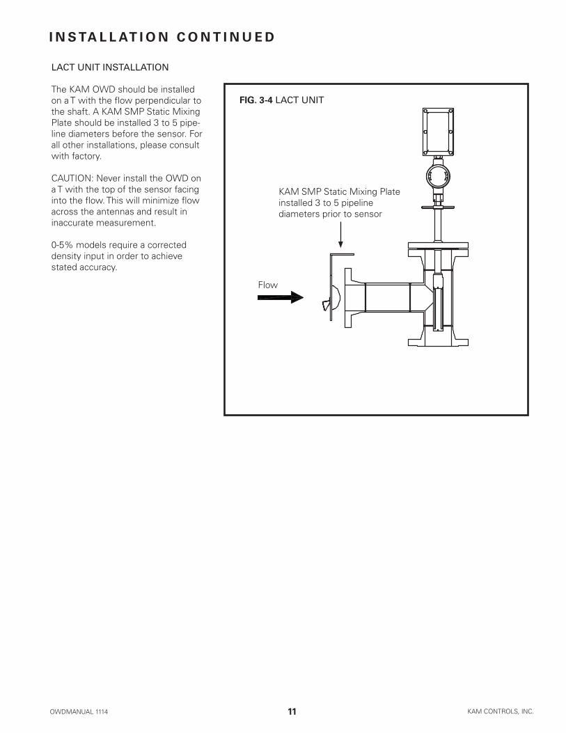
LACT UNIT INSTALLATION
TheKAMOWDshouldbeinstalledonaTwiththeflowperpendiculartotheshaft.AKAMSMPStaticMixingPlateshouldbeinstalled3to5pipe-linediametersbeforethesensor.Forallotherinstallations,pleaseconsultwithfactory.
CAUTION:NeverinstalltheOWDonaTwiththetopofthesensorfacingintotheflow.Thiswillminimizeflowacrosstheantennasandresultininaccurate measurement.
0-5%modelsrequireacorrecteddensityinputinordertoachievestated accuracy.
Flow
KAMSMPStaticMixingPlateinstalled3to5pipelinediameters prior to sensor
FIG. 3-4 LACT UNIT

OWDMANUAL 1114 KAM CONTROLS, INC.12
I N S TA L L AT I O N C O N T I N U E D
GENERAL INSTALLATION DO'S AND DON'TS
Always install OWD® sensorswiththeelectronics enclosure shadedfromdirectsunlight.
DONOTuseTeflontapeonthreadscon-nectingtotheOWD® flowthroughsensor.DOuseliquidthreadsealant.

OWDMANUAL 1114 KAM CONTROLS, INC.13
I N S TA L L AT I O N C O N T I N U E D
Removealltheprotectivepackagingmaterials,andensurethattheOWD®sensorwasnotdamagedduringtransit.
REMINDER:PleaserefertotheInstallationFlowRequirementsonP.9ofthismanualtoensurepropersensorplacementwhereatallpossible.FlowconditionsmustsatisfyAPIMPMSChapter8.2requirementsinordertoachieveaccurateOWDperformance.
Incoldweather,ifOWDisexposedtoanopenenvironment,KAMCONTROLSrecommendsoperatorsinsulatetheOWD,andifthepipelineisheatedthattheheatingtracebeextendedtoincludetheOWD.
IfthepipelineisnotgoingtoflowforextendedamountoftimeandthepipeisnotheatedthenOWDshouldbetakenouttoavoiddamagetothesensorprobebyfreezingwater.
PRIOR TO INSTALLATION
MAIN LINE INSTALLATION
INITIAL CALIBRATION
TheKAM® OWD®sensorshouldbeinstalledaccordingtoFIG.3-13.Afull-openingballvalveisusedtoisolatetheOWD®sensorfromthepipelineduringinstallationorremoval.ThesealhousingoftheOWD®sensorallowstheprobetobeinsertedandremovedfromthepipeunderpressureandflowconditions.Itistheuser’sresponsibilitytoensurethattheOWD®sensorbeplacedatthemostrepresentativepointwithintheflowprofile(seelocationrecommendationsabove).TheOWD®sensorshouldbeinsertedsothatthewindowoftheprobeislocatedinthecenterofthediameterofthepipeline.
Note:Iflinepressureexceeds100psi,useaKAM®
ITInsertionToolwheninstalling/removingtheKAM® OWD® sensor.
LockingCollar
SealHousing
Full-openingBall Valve
SocketCapScrew
FIG. 3-5 KAM® OWD® INSTALLED ON A MAIN PIPE
ThoughtheOWDhasbeencalibratedinthefactory,operatorsshouldconductaninitialcalibrationinprocessconditions.Thiscanbedoneintwoways:
Off-line:Priortoinstallation,operatorscangothroughtheproceduresforoff-linecalibrationoutlinedonpage25ofthismanual.Thismethodrequiressamplesof100%producedwateranddryoiloroilwithaknownpercentageofwater.
On-line:Afterinstallation,operatorscanfollowcalibrationproceduresforin-linecalibrationoutlinedonpage25ofthismanual.Thismethodrequiresaccuratesamplingandsampleprocessing.

OWDMANUAL 1114 KAM CONTROLS, INC.14
Priortomountingverifythatthetipofthesensorisallthewayinsidethesealhousing.FIGS.3-14,3-15. Ifsensorisnotfullyenclosedinsidethesealhousing,pulltheshaftbackuntiltheprobeisallthewayinthesealhousingandtightentheSocketCapScrewsonthelockingcollar.ThiswillpreventtheOWD®shaftfromslidingandtheprobefromgettingdamagedduringmounting.
1.
2.
FIG. 3-6
FIG. 3-7
I N S TA L L AT I O N C O N T I N U E D
Measurethedistance(D1)fromtheoutsidediameterofmainpipetotheendoftheconnectionwheretheOWD®sensorisgoingtobeinstalled.FIG.3-16.
D1
D1
CalculatetheminimuminsertiondistancefortheOWD®.
Minimuminsertiondistance(MID)=D1 + PipeWallThickness(WT)+GasketThickness+A(SeeTABLE3-16)
ExampleforD1=16",WT=1/4",GasketThickness=1/8"anda0-100%OWD® sensor:
MID=16+1/4+1/8+3MID=193/8"
4.
3.
FIG. 3-8
A/INCHES
7"
5"
3"
OWD®RANGE
0-5%SENSOR
0-20%SENSOR
0-100%SENSOR
TABLE 3-9

OWDMANUAL 1114 KAM CONTROLS, INC.15
I N S TA L L AT I O N C O N T I N U E D
MeasurethecalculatedMIDfromthetopoftheLockingCollarandplaceamarkwithapermanentmarkerortapeontheShaft.FIG.3-18.
5.
MID
6. BoltorscrewtheOWD®sensortothevalveordesignatedinstallationlocation.(KAMCONTROLSrecommendsusingthreadsealantandnotTeflontapeforthethreadedOWD®).
Openfullopeningvalve.7.
LoosenSocketCapScrewsonthelockingcollar.8.
FIG. 3-10
PushOWD®sensorinuntilthemarkisatthetopedgeofthelockingcollar.EnsurethatOWD®flowindicatorisalignedwithpipelineflowdirection.FIG.3-19.
9.
Mark
Re-tightentheSocketCapScrews.
TightenthehexnutsholdingdowntheLockingCollaronehalfturn.(Fig.3-19)Theseshouldneverbeover-tight-ened.Theirmajorfunctionistoapplylightpressureonthechevronpackingtoensureasealbetweenthesealhousingbodyandtheinsertionshaft.
10.
11.
REMOVING THE OWD® SENSOR
ToremovetheOWD®sensor,firstshutoffpowertotheinstrument.LoosentheSocketCapScrewontheLockDownCollar.SlidetheOWD®sensorupwarduntiltheproberestsinsidethesealhousing.Next,closetheFull-openingBallValvetightly.Drainoilfromvalveifpossible.TheOWD®sensormaynowbeunboltedfromthesystem.
Note:Iflinepressureexceeds100psi,useaKAM® ITInsertionToolwheninstalling/removingtheKAM® OWD® sensor.
RemovalshouldbeconductedinaccordancewithallregionalandClassrequirements.
FIG. 3-11
Hex Nuts

OWDMANUAL 1114 KAM CONTROLS, INC.16
I N S TA L L AT I O N C O N T I N U E D
REMOVING THE OWD® SENSOR FROM FLOW THROUGH SPOOLS WITH FIXED INSERTION
ToremovetheOWD®sensor,firstshutoffpowertotheinstrument.Discontinueflowinloopfromthemainlineanddrainfluidfromloop.Theprobecanremovedfromthehousingbyremovingscrewsoncollar.Fig.3-23.Theprobecanthenbeliftedfromthecellfortesting/inspection/cali-bration purposes.
Removalshouldbeconductedinaccordancewithallre-gionalandClassrequirements.
FIG. 3-12
Hex screws

OWDMANUAL 1114 KAM CONTROLS, INC.17
I N S TA L L AT I O N C O N T I N U E D
WIRING
Kam Controls Incorporated 3939 Ann Arbor Drive Houston, TX 77063 USA Tel + 1 713 784 0000 Fax + 1 713 784 0001 www.Kam.com E-mail [email protected]
OW
D Rev. 4
KAM OWDMade in USA
24V (+) in
4-20mA (-)
24V (-) in
4-20mA (+)
ANA OUT (-)
ANA OUT (+)
DIG OUT (-)
DIG OUT (+)
AIN2
RS485 (+)
RS485 (-)
GND
RS232 RX
GND
RS232 TX
DIG IN (-)
DIG IN (+)
GND
FIG. 3-13 WIRING DIAGRAM 0-100% MODELS
D1R1
+

OWDMANUAL 1114 KAM CONTROLS, INC.18
I N S TA L L AT I O N C O N T I N U E D
INPUTS
24V(–)IN GND24V(+)IN 24-30VDC
DIGIN(–) Pulseinput,discreteinputfordifferentmodesofoperation(0or5volt)DIGIN(+)
AIN2 DensityIn–Notrequiredon0-100%models
OUTPUTS
4-20mA(–) Currentoutput,sourcepowered.Settorequisitepercentwateratfactory.4-20mA(+)
ANOUT(–) Canbe4-20mAoranalogvoltage(usedforlocaldisplayortopassdensitytoPLC)ANOUT(+)
DIGOUT(–) Alarmorrelay(digitalcontactclosure)DIGOUT(+)
INPUT/OUTPUT
RS232 Consoleport–communicationinterfaceforcalibration,connectiontoPLCRS485 Modbusinterface
LED INDICATORS
D1 Power
SERIAL PORT CONNECTIONS
DB9(female)
5 GND3 RS232RX2 RS232TX
AllwiringandmaintenanceontheKAMOWDmustbedoneinaccordancewithregionalandclassificationre-quirements.Itistheuser'sresponsibilitytounderstandtheserequirements.
ItisalsorecommendedthattheOWDbewiredwithflexiblewiring/conduitwithadditionalslack/lengthinthewiretoaccommodateinsertion,removal,andtesting.
Operator'sshouldtakeallpossibleprecautionstoavoidanymoisturefromenteringtheelectronicsenclosure.Theenclosureshouldnotbeleftopenininclementweatherorforlongperiodsoftime,especiallyduringopera-tionascondensationwillaccumulate.Lidshouldbetightlyscrewedshut,allconduitsshouldbesealedandsecuredinaccordancewithregionalandclassificationrequirements,andunused3/4"NPTopeningsshouldbesealwithprovidedplug.Donotpowerwashtheunit.

OWDMANUAL 1114 KAM CONTROLS, INC.19
FIG. 3-14 WIRING DIAGRAM OWD MODELS WITH RANGES OTHER THAN 0-100%
I N S TA L L AT I O N C O N T I N U E D
3939 Ann Arbor DriveHouston, TX 77063 USATel + 1 713 784 0000Fax + 1 713 784 0001E-mail [email protected] www.Kam.com
Made in USA
V (+) in
AGND
V (-) in
AOUT0
AGND
AOUT1
DENSITY
DOUT
GND
GND
RS485 (+)
RS485 (-)
GND
DIN
GND
GND
RXDO
TXDO
TEC+
D2
24-30VDCPower
4-20mAOutput
4-20mAOutputoranalogvoltage
Alarm or Relay
Density InputFactoryUse
RS485
RS232
FactoryUse
Main power indicator
Sharedground(RS485andRS232)

OWDMANUAL 1114 KAM CONTROLS, INC.20
INPUTS
V(–)IN GNDV(+)IN 24-30VDCPower(external110/220adaptersavailable)
DIGIN(–) Pulseinput,discreteinputfordifferentmodesofoperation(0or5volt)DIGIN(+)
DENSITY Forcorrecteddensitysignalonall0-5%orlessmodels
OUTPUTS
AOUT0 Currentoutput,sourcepowered.Settorequisitepercentwaterrangeatfactory.
AOUT1 Canbe4-20mAoranalogvoltage(usedforlocaldisplay,ortopassdensityortemperaturetoPLC)
DOUT Alarmorrelay(digitalcontactclosure).Optional–cansinkupto40Vand200mA.
INPUT/OUTPUT
RS232 Consoleport–communicationinterfaceforcalibration,connectiontoPLCRS485 Modbusinterface
AllwiringandmaintenanceontheKAMOWDmustbedoneinaccordancewithregionalandclassificationre-quirements.Itistheuser'sresponsibilitytounderstandtheserequirements.
ItisalsorecommendedthattheOWDbewiredwithflexiblewiring/conduitwithadditionalslack/lengthinthewiretoaccommodateinsertion,removal,andtesting.
Operator'sshouldtakeallpossibleprecautionstoavoidanymoisturefromenteringtheelectronicsenclosure.Theenclosureshouldnotbeleftopenininclementweatherorforlongperiodsoftime,especiallyduringopera-tionascondensationwillaccumulate.Lidshouldbetightlyscrewedshut,allconduitsshouldbesealedandsecuredinaccordancewithregionalandclassificationrequirements,andunused3/4"NPTopeningsshouldbesealwithprovidedplug.Donotpowerwashtheunit.
I N S TA L L AT I O N C O N T I N U E D

OWDMANUAL 1114 KAM CONTROLS, INC.21
K A M O W D O P E R AT I O N
ConnecttheRS232cabletotheOWDRS232port.TolaunchHyperterminal,clickonOWDicononyourdesktop.Nametheconnection"OWD"andhitreturn.Fig.4-1.
HYPERTERMINAL SOFTWARE
1.
2. YouwillbepromtedtoselectaCOMport.IfthecomputerhasanRS232port,mostlikelyitwillbeCOM1.IfyouareusinganadapterlikeaUSBtoRS232ConvertertheCOMportwillbewhateverportisassignedtotheadapter.Click"OK."Fig.4-2.
FIG. 4-1
FIG. 4-2
HyperterminalsoftwareisusedduringtestingandcalibrationoftheOWD.
PriortobeginningmakesureHyperterminalsoftwarehasbeeninstalledonyourPC.Thesoftwareisincludedwithyourinstrument,andisalsoavailableasafreedownloadfromnumerouswebsites.AnRS232cableforconnect-ingyourPCtotheOWDhasbeensuppliedwiththeOWDaswellasanadaptorIfyourcomputerdoesnothaveanRS232 serial port.

OWDMANUAL 1114 KAM CONTROLS, INC.22
UsethesettingsshowninFig.4-3andclickOK.
Clickonthepropertiesicon.FIG.4-4
FIG. 4-3
FIG. 4-4
FIG. 4-5Clickonthesettingstab.FIG.4-5
ClickontheASCIIsetupbutton.
K A M O W D O P E R AT I O N C O N T I N U E D
3.
4.
5.
6.

OWDMANUAL 1114 KAM CONTROLS, INC.23
K A M O W D O P E R AT I O N C O N T I N U E D
CheckthewindowforEchoTypedCharactersLocallyandclickOK.HyperterminalisnowsetupforoperationwiththeOWD.
FIG. 4-6
FIG. 4-7
7.
8. Youwillseeablankscreen.HitentertoseeOWDprompts.FIG.4-7.

OWDMANUAL 1114 KAM CONTROLS, INC.24
CAPTURING HYPERTERMINAL DATA
d:DumpCalibrations–displayscalibrationcurves
c:EnterCalibration–thisisNOTusedtocalibratetheOWDandisforfactoryuseonly
o:Enteroffset–allowsuserstoenteroffsetsmanually.TheseshouldbedeterminedbyatrainedtechnicianorKAMCON-TROLS representative.
R:4-20mARange–setsthe4-20mArange.Seepage29forinstructionsonhowtochangetherange.
s:Savecalibrations/inputs
Z:Displaysallsensorvalues
L:Calibrate–forcalibrationinstructions,seepage28
M:ChangeModbusAddress:Factorydefaultis"1"
T/u/v/W/i:ThesearefactorysettingsandshouldNOTbeinputbyusers
OWD PROMPTS
K A M O W D O P E R AT I O N C O N T I N U E D
Hyperterminaldatacanbecapturedinmultipleways.Userscansimply"selectall"andthencutandpastethedataintoaworddocument.OrfromtheOWDdatascreen,clickon"Transfer."Fig.4-8.Select"CaptureText"fromthedrop-downmenu.Selectandnameandlocationforthedatafile,andclick"Start."Whenyouaredonecapturingdata,clickon"Transfer"againandselect"Stop."
FIG. 4-8
OWDMANUAL 1114 KAM CONTROLS, INC.25
HOW TO CALIBRATE THE KAM® OWD® USING BRINE AND DRY OIL
ThoughtheOWDhasbeencalibratedinthefactory,itshouldbecalibratedinprocessconditionspriortouse.Thiscanbedoneusing100%brine(producedwater)and100%dryoilinbucketsasoutlinedbelow,oritcanbedonewithonlinesampling.Forthebrine/dryoilmethod,inadditiontofluidsamples,operatorswillneedappropriatetoolsfortheextractionoftheOWD,anRS232cable(supplied)oranRS232/USBadapter,andaPCequippedwithHyperterminalsoftware.
K A M O W D O P E R AT I O N C O N T I N U E D
ON-LINE CALIBRATION OF THE KAM® OWD®
ConnectPCtotheOWDsensorviasuppliedRS232serialportorRS232/USBadapter.LaunchHyperterminalandhitENTER.ForHyperterminalsetup,seepage21.
Takeanaccurate(fullyhomogenous)samplefromthepipelineclosetothesensorlocationonthepipeline,andatthesametimetype"L"forcalibrationintheHyperterminalandhitENTER.A"Water%"promptwillappear.
1.
2.
PLEASENOTE:Thefollowingcalibrationstepsshouldonlybeconductedduringinitialinstallationwithprocesscon-ditions,whenprocessconditionshavechanged,orwhenOWDreadingsindicateaslightdriftoffacceptableaccura-cies.YouwillneedanRS232cable(supplied)oranRS232/USBadapter,aPCequippedwithHyperterminalsoftware,andameansforcollectedandmeasuringsamples.
IftheOWDhasbeeninstalled,removefromthelineaccordingtotheinstructionsonpage16forinsertablemod-elsandpage18formodelsinstalledonfastloopsandMLMeasurementLoops.CleantheOWDsensoraccord-ingtheguidelinesonpage28ofthismanual.
RestorepowertotheOWDandconnecttoaPCviaRS232orRS232/USBadapter.InitiateHyperterminalsetup.ForinformationonsettingupHyperterminalsoftware,seepage21.
LettheOWDsensorwarmupfor20minutes.
Insertthesensorinabucketwithbrine(producedwater).Probeshouldremaininbrineuntilastabilizedtem-peratureisobserved.Readingsshouldshow100%waterintheHyperterminal.Asallwaterincrudeoilhassalt,theOWDsensorhasalreadybeencalibratedforsaltwater.Youwillnotgetanaccuratereadingifyouusefreshwaterfortesting.Itshouldalsoshow20mAifthemArangeiscalibratedfor0-100%whichyoucanmeasureattheoutputterminal.Regardlessofreadings,thesensorshouldberecalibrated.
Enter"L"ontheHyperterminalinterfaceandhitENTER.A"Water%"promptwillappear.Enter"100."HitENTER.Type"s,"thenENTERtosave.
Removeprobefrombrine,andthoroughlycleananddrytheprobe.
InserttheOWDsensorintoabucketorajarfilledwithasampleofdryoil.InordertoaccuratelytesttheOWDsensor,youmustuseoilthatdoesnothaveanywaterinitorwhichhasaknown,lowpercentageofwater.ThewaterpercentagereadingintheHyperterminalshouldshow0%orreflecttheknownwaterpercentage.
Enter"L"ontheHyperterminalinterface.A"Water%"promptwillappear.Enter"0"ortheknownpercentageofwater.HitENTER.Type"s,"thenENTERtosave.
TheOWDhasnowbeencalibratedtoprocessconditionsandcanbeinstalled.
1.
2.
3.
4.
5.
6.
7.
8.
9.

OWDMANUAL 1114 KAM CONTROLS, INC.26
DeterminewaterpercentageinsampleusingaKAMKarlFischerMoistureAnalyzer(recommended),orappropri-atemethod.EnterthedeterminedsamplewaterpercentageintoHyperterminalpromptandhitENTER.
Type"S",thenhitENTERtosave.
TheKAM® OWD® is now calibrated.
Thisprocesscanberepeatedifthesampletakenwasabadsampleorthepercentofwaterobtainedfromthesampletakenwasnotaccurate.
5.
4.
K A M O W D O P E R AT I O N C O N T I N U E D
HOW TO CHANGE THE HIGH/LOW (4-20 mA) RANGE
ToenterorchangethedesiredrangefortheOWDsensor,type“R”andhitENTER.Promptswillappearforthelowandthenthehighendsoftherange.
Afterenteringboth,type“S”tosave.TherangehasbeensetandtheHyperterminalwillreturntotheOWDOptimizer prompt menu.
1.
2.
SETTING UP A MODBUS INTERFACE
TosetModbusvariables,type"M"andhitENTER.
ThepromptisforanIDfortheslavedevice.ThisIDMUSTBEUNIQUEfromanyotherModbusdeviceconnectedandavaluebetween1-255.
SYSTEMSETTINGS:
Modbus Baudrate: 9600.
Protocol is RTU Modbus.
SeeAPPENDIXAfordesignatedMODBUSRegisters.
1.
2.
3.

OWDMANUAL 1114 KAM CONTROLS, INC.27
IfprobeisremovedfromthelineforinspectionNEVERusesharpormetallicobjectssuchasaknifeorscrewdrivertocleantheantenna,especiallytheTefloncoatedantenna.DoNOTpowerwashtheunit.
Instead,toremoveanyoilresiduesforvisualinspectionuseacleanclothwithoilsolventorpartwasher.Preferredsolventsinclude,anypetroleumsolventsuchasmineralspirits,xylene,toluene,gasoline,ordiesel.DonotuseWD40orotherchemicals.
Ifyouhaveaquestionregardingcleaningsolvents,pleasecontactKAMCONTROLSdirectlyat+17137840000,oremail:[email protected]
Duringinspection,ensurethattherearenoforeignobjectsstuckintheprobeorattachedtotheantennas.
M A I N T E N A N C E
CLEANING AND INSPECTION
TROUBLESHOOTING
IfOWDdatabeginstodifferslightlyorgraduallyfromsamplingdataandfallsoutsideofacceptableaccuracies,thisismostlikelycausedbydrift.TheOWDshouldberecalibratedusingtheon-linerecalibrationprocedureoutlinedonpage25.
IfOWDdatasuddenlyveersfromhistoricalnormsorsamplingdata,itneedstoberemovedfromthelineandinspect-edusingthestepsoutlinedbelow.
RemovetheOWDfromthelineaccordingtotheinstructionsonpage16forinsertablemodelsandpage18formodelsinstalledonfastloopsandMLMeasurementLoops.CleantheOWDsensoraccordingtheguidelinesabove,andcheckforanydebrisintheprobeorontheantennasthatcouldaffectmeasurement.Checkthecondi-tionofbothantennas.
Ifthereisdebriscloggingthesensororcoatingtheantennasinanyway,thisismostlikelythecauseofanymea-surementanomalies.OncetheOWDhasbeencleaned,itcanbereinstalled.Itdoesnotneedrecalibration.
Ifthereisnoevidenceofdebris,theOWDmustbetestedinordertodeterminethecauseofthemeasurementerror.Thisrequiressamplesof100%brine(producedwater)anddryoiloroilwithaknown,lowpercentageofwater,anRS232cable(supplied)oranRS232/USBadapter,andaPCequippedwithHyperterminalsoftware.
ConnecttheOWDtoaPCviaRS232orRS232/USBadapter,andturnthepoweron.InitiateHyperterminalsetup.ForinformationonsettingupHyperterminalsoftware,seepage22.
LettheOWDsensorwarmupfor20minutes.
Insertthesensorinabucketwithbrine(producedwater).Probeshouldremaininbrineuntilastabilizedtempera-tureisobserved.Asallwaterincrudeoilhassalt,theOWDsensorhasalreadybeencalibratedforsaltwater.Youwillnotgetanaccuratereadingifyouusefreshwaterfortesting.Captureandsavescreendataaccordingtoinstructionsoutlinedonpage24.
1.
2.
3.
4.
5.
6.

OWDMANUAL 1114 KAM CONTROLS, INC.28
Thoroughlycleananddrytheprobe.
InserttheOWDsensorintoabucketorajarfilledwithasampleofdryoil.InordertoaccuratelytesttheOWDsensor,youmustuseoilthatdoesnothaveanywaterinitorwhichhasaknown,lowpercentageofwater.
Captureandsavescreendataaccordingtoinstructionsoutlinedonpage24.
CaptureddatashouldbesenttotheKAMCONTROLSfactoryforanalysisoranalyzedbyaKAMCONTROLStrainedtechnician.Thetechnicianwillthenadvisetheoperatoronthenextsteps.
7.
8.
9.
10.
M A I N T E N A N C E C O N T I N U E D

OWDMANUAL 1114 KAM CONTROLS, INC.29
DISASSEMBLY
2.
3.
FIG. 5-2
SMA ConnectorsRTD
Unscrewlidtoroundjunctionbox(FIG.5-1)andensurethatcablesaresomewhatslack.Ifnot,untie/loosenthecablespriortopullingprobeawayfromhous-ing.
SlowlypullProbeawayfromHousingtogainaccesstotheSMA connectors. Do not pull too hardortoofarasthewirescanbedamaged.FIG.5-2
Removeall(6)8-32SetScrewsusingthe5/64"AllenWrench.MakesurethatthewrenchinfullyinsertedortheSetScrewswillstrip.FIG.5-1
1.
FIG. 5-1
8-32SetScrewsJunction Box Lid
ANTENNA REPLACEMENT
1.PhillipsScrewdriverSize02.1/16"AllenWrench3.5/64"AllenWrench4.5/16"AllenWrench
1. Stainless Antenna2. Titanium Antenna3.(2)2-004O-rings4.(2)2-009O-rings5.MediumStrengthLoctite
TOOLS REQUIRED
MATERIALS REQUIRED
Contact KAM CONTROLS at +1 713 784 0000, Faxto+17137840001,[email protected]:OWDANT
M A I N T E N A N C E C O N T I N U E D

OWDMANUAL 1114 KAM CONTROLS, INC.30
Makeanoteofwhichcolorcablegoestowhichantenna.Forexample:Redcablegoestogreenantenna.
LoosenandunscrewcompletelytheSMAConnectorsusingthe5/16"AllenWrench.
PulltoremovetheRTD.DONOTpullfromthewires.FIG.5-2
7.
6.
5.
4.
8.
Unscrewthe(4)4-40ScrewsonthetopofthesensorusingthePhillipsScrewdriverSize0.FIG.5-3
RemovetheCoverfromtheSensor.FIG.5-4
FIG. 5-3 4-40Screws
FIG. 5-4
Removethe(4)SetScrewsatthebottomoftheSensorusingthe1/16"AllenWrench.Besuretoinsertwrenchfullyorscrewswillstrip.FIG.5-5
PushtheBottomCoverfromtheinsideoftheSensoruntilitiscompletelyfree.FIG.5-5
9.
10.
FIG. 5-56-32x¼"SetScrew
M A I N T E N A N C E C O N T I N U E D

OWDMANUAL 1114 KAM CONTROLS, INC.31
Pushingfromthebottom,removetheAntennas.FIG.5-611.
FIG. 5-6
RemovetheAntennasfromthePEEKSealHoldersbyturningthemcounterclockwise.FIG.5-7
SlidetheSealHolderCoversofftheAntennas.FIG.5-7NOTE:TheSealHolderCoverforthestainlessandtitaniumantennasaredifferent.Thecoverforthetitaniumhasalargerhole.
Removethe2-009and2-004O-ringsfromtheSealHolder.FIG.5-7
CleanSensorBodywithpartswasherandletitdry.
FIG. 5-7
12. 13.
14.
2-009O-ring
2-004O-ring
Seal Holder CoverSeal Holder
15.
M A I N T E N A N C E C O N T I N U E D

OWDMANUAL 1114 KAM CONTROLS, INC.32
2-009O-ring
Installthenew2-009O-ringsontheSealHolder.FIG.5-8A
ScrewthenewAntennasintotheSealHolder.TheAntennasneedtoextend.175–.180"fromthetopoftheSealHolder.FIG.5-8A
Slidethenew2-004O-ringsontheAntennas.FIG.5-8B
SlideSealHolderCoversbehindthe2-004O-rings.MakesuretheusetheSealHolderCoverwiththelargercenterholewiththeCoatedAntenna.FIG.5-8B
Addasmallamountofgreasetothe2-004O-rings.
Pushthe2-004O-ringsinsidetheSealHolderusingtheSealHolderCovers.FIG.5-8C
REASSEMBLY
1.
2.
3.
4.
5.
6.
FIG. 5-8 .175–.180"
A.
B.
C.
2-004O-ring Seal Holder Cover
Addasmallamountofgreasetothe2-009O-rings.
InsertSealHolder/AntennaassemblyintotheSensorBody.FIG.5-9
7. 8.
FIG. 5-9
M A I N T E N A N C E C O N T I N U E D

OWDMANUAL 1114 KAM CONTROLS, INC.33
PlaceSensorCoverontotheSensorBody.BecarefultoensurethattheholesfortheRTDareinalignment.
AddasmallamountofLoctitetothe(4)4-40ScrewsandinstallthemintotheSensorBody,holdingtheCoverinplace.FIG.5-10
PushBottomCoverbackintoplace.MakesureholesalignwiththeAntennas.
AddLoctitetoall(4)6-32ScrewsandinstallthemintotheSensorBody,securingtheBottomCover.FIG.5-11
9.
10.
11.
12.
FIG. 5-116-32Screw
FIG. 5-104-40Screws
M A I N T E N A N C E C O N T I N U E D

OWDMANUAL 1114 KAM CONTROLS, INC.34
ConnecttheCablestotheSensorwiththeSMAconnectors.NOTE:DonotaddLoctitetotheSMAConnectors.Theyshouldbefingertightandthenturned1/16ofaturnwiththe5/16"Wrench.
EnsurethattheproperCablecolorsareconnectedtotheproperAntennas:redtotitaniumandblacktostainless.
InserttheRTDintoSensorBody.FIG.5-12
PushSensorbackintoplace.
Alignthewindowsothatitwilldirectlyfacethedirectionoftheflow.FIG.5-13
AddLoctitetoall(6)8-32SetScrewsandinstallthembackinSensor.FIG.5-14
13.
14.
15.
16.
17.
18.
FIG. 5-14
8-32SetScrews
FIG. 5-12
SMA Connectors
RTD
Flow
FIG. 5-13
M A I N T E N A N C E C O N T I N U E D

OWDMANUAL 1114 KAM CONTROLS, INC.35
A P P E N D I X A : M O D B U S I N T E R FA C E R E G I S T E R S
01 Discrete Coil Status
02 Discrete Input Status
03HoldingRegister
Reads output coil status, digitaloutputs
Readsstateofindividualdigitalinputs
Reads and writes to theDACchannels(0-3).Takesaconvertedfloatvalue(from2unsignedintvalues)andupdatestheDACoutputvalues(inVolts0-10VDC).
0x00001–0x00016:Digitaloutputs0–15
0x10001–0x10024:Digitalinputs0–23
0x40001–0x40002:FloatvalueforDAC00x40003–0x40004:FloatvalueforDAC10x40005–0x40006:FloatvalueforDAC20x40007–0x40008:FloatvalueforDAC040100–40999:16–bitvalues41000–41999:32–bitvalues42000–44999:Floatvalues45000–47299:Modbusregisters
40100: Alarm setpoint40101:Alarmsetpointpriortochange40102:Onoroffalarmreport40103:Onoroffalarmreport40104:Onoroffalarmreport40105:Truewhenvalueoveralarmvaluefordead-band time.Resetwhenvaluebelowalarmvaluefor dead-bandtime.40106:Signaltoresettransaction40107:Watercontentinteger40108: AD0 raw value40109: AD1 raw value40110:Low-endoutputat4mapriortochange40111:Low-endoutputat4ma40112:High-endoutputat20ma40113:High-endoutputat20mapriortochange40114:Numberofuserblocksaves(Limitto50,000)41000: Sample period in seconds41001:Sampleperiodinsecondspriortochange41002:Alarmdead–bandinter-valuetimer41003:Alarmdead–bandstarttime41004:Alarmdead–bandcurrenttime41005:Alarminter-valuetimer41006: Alarm start time41007: Alarm current time41008:Arrayoftimeofalarms41009:Arrayoftimeofalarms41010:Arrayoftimeofalarms41011:Valueattimeofalarm41012:Valueattimeofalarm41013:Valueattimeofalarm.Resetwhenvaluebelow alarmvaluefordead-bandtime.41014:Amountofmeasuredmaterial41015:Materiallesswater41016:Averagewater41017: Transaction intervalue timer41018: Transaction start time41019: Sample period in second
MODBUSFUNCTION USE REGISTERS

OWDMANUAL 1114 KAM CONTROLS, INC.36
A P P E N D I X A C O N T I N U E D
41020: Sample start time41021: Sample current time41022:Mode:oilcontinuous/watercontinuous41023:Modifytable:0=oilcontinuous 1=water continuous41024:Setto1tosignaltablemodificationready.Resetto –1toindicatenotready.41025:Setto1tosignalwriteUB41026:Modifysensor1TempCorf:1 Modifysensor2TempCorf:241027:Setto0–19toindicatetemperaturecurve modificationready.Resetto–1toindicatenot ready.41028: Temperature value input by user4102941030–41049:Temperaturetabletemperatures42000: Trend 042001: Trend 142002: Trend 242003: Trend 342004: Trend 442005:Trend542006: Trend 642007: Trend 742008: Trend 842009: Trend 942010: Trend 1042011: Trend 1142012: Trend 1242013: Trend 1342014: Trend 1442015:Trend1542016: Trend 1642017: Trend 1742018: Trend 1842019: Trend 1942020: AD0 input42021: AD1 input42022:AD2oil/watercontinuousinput42023: DA0 output42024: Water content oil continuous sensor 142025:Watercontentoilcontinuoussensor242026: Water content water continuous sensor 142027: Water content water continuous sensor 242028:Watercontentfloat42029:Sensor1offsetinputbyuser42030:Sensor1offsetinputbyuser42031:Sensor2offsetinputbyuser42032:Sensor2offsetinputbyuser42033:StorageregisterforModbustableindexwater value42034StorageregisterforModbustablesensor1value42035StorageregisterforModbustablesensor2value42036:AD3temperaturevoltageinput42037: Temperature value input
MODBUSFUNCTION USE REGISTERS

OWDMANUAL 1114 KAM CONTROLS, INC.37
MODBUSFUNCTION USE REGISTERS
42038:Temperatureinputlowvoltage42039: Temperature input low value42040:Temperatureinputhighvoltage42041:Temperatureinputhighvalue42042: Sensor 1 temperature correction42043: Sensor 2 temperature correction42044:Waterfactor0.00–9.9942045:Sensor1temperaturecorrection0–10v42046: Sensor 1 temperature correction 10v42047:Sensor1temperaturecorrection0–10v42048: Sensor 1 temperature correction 10v42049:Sensor1temperaturecorrection0–10v42050:Sensor1temperaturecorrection10v42051:Sensor1temperaturecorrection0–10v42052:Sensor1temperaturecorrection10v42053:Sensor1temperaturecorrection0–10v42054:Sensor1temperaturecorrection10v42055:Sensor1temperaturecorrection0–10v42056:Sensor1temperaturecorrection10v42057:Sensor1temperaturecorrection0–10v42058:Sensor1temperaturecorrection10v42059:Sensor1temperaturecorrection0–10v42060: Sensor 1 temperature correction 10v42061:Sensor1temperaturecorrection0–10v42062: Sensor 1 temperature correction 10v42063:Sensor1temperaturecorrection0–10v42064: Sensor 1 temperature correction 10v4206542066420674206842069420704207142072420734207442075:Sensor1temperaturecorrection0–10v42076: Sensor 1 temperature correction 10v42077:Sensor1temperaturecorrection0–10v42078: Sensor 1 temperature correction 10v42079:Sensor1temperaturecorrection0–10v42080: Sensor 1 temperature correction 10v42081:Sensor1temperaturecorrection0–10v42082: Sensor 1 temperature correction 10v42083:Sensor1temperaturecorrection0–10v42084: Sensor 1 temperature correction 10v42085:Sensor1temperaturecorrection0–10v42086: Sensor 1 temperature correction 10v42087:Sensor1temperaturecorrection0–10v42088: Sensor 1 temperature correction 10v42089:Sensor1temperaturecorrection0–10v42090: Sensor 1 temperature correction 10v42091:Sensor1temperaturecorrection0–10v42092: Sensor 1 temperature correction 10v
03HoldingRegistercontinued
A P P E N D I X A C O N T I N U E D

OWDMANUAL 1114 KAM CONTROLS, INC.38
MODBUSFUNCTION USE REGISTERS 42093:Sensor1temperaturecorrection0–10v
42094: Sensor 1 temperature correction 10v40100: Alarm setpoint40101:Alarmsetpointpriortochange40102:Onoroffalarmreport40103:Onoroffalarmreport40104:Onoroffalarmreport40105:Truewhenvalueoveralarmvaluefordead-band time.Resetwhenvaluebelowalarmvaluefor dead-bandtime.40106:Signaltoresettransaction40107:Watercontentinteger40108: AD0 raw value40109: AD1 raw value40110:Lowendoutputat4mapriortochange40111: Low end output at 4ma40112:Highendoutputat20ma40113:Highendoutputat20mapriortochange40114:Numberofuserblocksaves(Limitto50,000)41000: Sample period in seconds41001:Sampleperiodinsecondspriortochange41002:Alarmdead-bandintervaluetimer41003:Alarmdead-bandstarttime41004:Alarmdead-bandcurrenttime41005:Alarmintervaluetimer41006: Alarm start time41007: Alarm current time41008:Arrayoftimeofalarms41009:Arrayoftimeofalarms41010:Arrayoftimeofalarms41011:Valueattimeofalarm41012:Valueattimeofalarm41013:Valueattimeofalarm.Resetwhenvaluebelow alarmvaluefordeadbandtime.41014:Amountofmeasuredmaterial41015:Materiallesswater41016:Averagewater41017: Transaction intervalue timer41018: Transaction start time41019: Sample period in second41020: Sample start time41021: Sample current time41022:Mode:oilcontinuous/watercontinuous41023:ModifyTable:0=oilcontinuous1=watercontinuous41024:Setto1tosignaltablemodificationready.Resetto –1toindicatenotready.41025:Setto1tosignalwriteUB41026:Modifysensor1TempCorf:1 Modifysensor2TempCorf:241027:Setto0–19toindicatetemperaturecurve modificationready.Resetto–1toindicatenot ready.41028: Temperature value input by user41030–41049:Temperaturetabletemperatures42000: Trend 0
03HoldingRegistercontinued
A P P E N D I X A C O N T I N U E D
OWDMANUAL 1114 KAM CONTROLS, INC.39
42001: Trend 142002: Trend 242003: Trend 342004: Trend 442005:Trend542006: Trend 642007: Trend 742008: Trend 842009: Trend 942010: Trend 1042011: Trend 1142012: Trend 1242013: Trend 1342014: Trend 1442015:Trend1542016: Trend 1642017: Trend 1742018: Trend 1842019: Trend 1942020: AD0 input42021: AD1 input42022:AD2oil/watercontinuousinput42023: DA0 output42024: Water content oil continuous sensor 142025:Watercontentoilcontinuoussensor242026: Water content water continuous sensor 142027: Water content water continuous sensor 142028:Watercontentfloat42029:Sensor1offsetinputbyuser42030:Sensor1offsetinputbyuser42031:Sensor2offsetinputbyuser42032:Sensor2offsetinputbyuser42033:StorageregisterforModbustableindexwater value42034StorageregisterforModbustablesensor1value42035StorageRegisterforModbustablesensor2value42036:Temperaturevoltageinput42037: Temperature value42038:Temperatureinputlowvoltage42039: Temperature input low value42040:Temperatureinputhighvoltage42041:Temperatureinputhighvalue42042: Sensor 1 temperature correction42043: Sensor 2 temperature correction42044:Waterfactor0.00–9.9941023:ModifyTable:0:oilcontinuous1:watercontinuous41024:Setto1tosignaltablemodificationready42031:StorageregisterforModbustableindexwater value42032:StorageregisterforModbustablesensor1value42033:StorageregisterforModbustablesensor2value
03HoldingRegistercontinued
MODBUSFUNCTION USE REGISTERS
A P P E N D I X A C O N T I N U E D

OWDMANUAL 1114 KAM CONTROLS, INC.40
MODBUSFUNCTION USE REGISTERS
A P P E N D I X A C O N T I N U E D
04InputRegister Reads individual calibratedvaluesofeachADCinput
0x30001–0x30002:FloatvalueofADC00x30003–0x30004:FloatvalueofADC10x30005–0x30006:FloatvalueofADC20x30007–0x30008:FloatvalueofADC30x30009–0x30010:FloatvalueofADC40x30011–0x30012:FloatvalueofADC50x30013–0x30014:FloatvalueofADC60x30015–0x30016:FloatvalueofADC70x30017–0x30018:FloatvalueofADC80x30019–0x30020:FloatvalueofADC90x30021–0x30022:FloatvalueofADC10