k5 software and instruction manual software manual 1510.pdf · kinco-k5 software manual 3 4.4.4...
TRANSCRIPT

Kinco-K5
Software Manual
1
Contents
CONTENTS .............................................................................................................................................................1
CHAPTER I WELCOME TO USE KINCOBUILDER ....................................................................................... 11
1.1 OVERVIEW ..................................................................................................................................................... 11
1.2 GENERAL DESIGNATION IN THE MANUAL ....................................................................................................... 12
CHAPTER II HOW TO USE KINCOBUILDER … A QUICK GUIDE ............................................................. 15
2.1 COMPUTER REQUIREMENTS ............................................................................................................................ 15
2.1.1 Minimum hardware requirements to run KincoBuilder: ........................................................................ 15
2.1.2 Minimum Software requirements to run KincoBuilder: ................................................................... 15
2.2 USER INTERFACE OF KINCOBUILDER .............................................................................................................. 17
2.3 USING KINCOBUILDER TO CREATE PROGRAMS FOR YOUR APPLICATIONS ........................................................ 19
2.3.1 Project Components ............................................................................................................................... 19
2.3.2 Where to store the Project Files ............................................................................................................. 20
2.3.3 Importing and Exporting a Project ........................................................................................................ 20
2.4 HOW THE CPU EXECUTES ITS TASKS IN A SCAN CYCLE? ................................................................................ 23
2.5 HOW TO CONNECT THE COMPUTER WITH THE KINCO-K5 .................................................................................. 25
2.6 HOW TO MODIFY THE CPU‟S COMMUNICATION PARAMETERS ........................................................................... 28
2.7 EXAMPLE: COMMON STEPS TO CREATE A PROJECT .......................................................................................... 29
CHAPTER III CONCEPTS FOR PROGRAMMING ............................................................................................ 37
3.1 POU (PROGRAM ORGNIZATION UNIT) ............................................................................................................ 37
3.2 DATA TYPES ................................................................................................................................................... 39
3.3 IDENTIFIERS ................................................................................................................................................... 41
3.3.1 How to define an identifier ..................................................................................................................... 41

Kinco-K5
Software Manual
2
3.3.2 Use of Identifiers .................................................................................................................................... 41
3.4 CONSTANT ...................................................................................................................................................... 42
3.5 VARIABLES ..................................................................................................................................................... 44
3.5.1 Declaration ............................................................................................................................................ 44
3.5.2 Declaring Variables in KincoBuilder ..................................................................................................... 45
3.5.3 Checking Variables ................................................................................................................................ 45
3.6 HOW TO ACCESS PLC MEMORY ...................................................................................................................... 46
3.6.1 Memory Types and Characteristics ........................................................................................................ 46
3.6.2 Direct Addressing ................................................................................................................................... 48
3.6.3 Indirect Addressing ................................................................................................................................ 55
3.6.4 Memory Address Ranges ........................................................................................................................ 58
3.6.5 Function Block and Function Block Instance ........................................................................................ 60
3.6.6 Using FB Instances ................................................................................................................................ 62
3.6.7 FB Instances Memory Ranges ................................................................................................................ 64
CHAPTER IV HOW TO USE KINCOBUILDER … BASIC FUNCTIONS ...................................................... 65
4.1 CONFIGURING GENERAL SOFTWARE OPTIONS ................................................................................................. 65
4.2 ABOUT DOCKING WINDOWS ........................................................................................................................... 68
4.3 CONFIGURING HARDWARE .............................................................................................................................. 69
4.3.1 How to open the Hardware window ....................................................................................................... 70
4.3.2 Copy and paste the hardware configuration in different projects........................................................... 70
4.3.3 Add/Remove Modules ............................................................................................................................. 70
4.3.4 Configuring Module Parameters ........................................................................................................... 71
4.4 THE INITIAL DATA TABLE ................................................................................................................................ 82
4.4.1 Opening the Initial Data Table ............................................................................................................... 82
4.4.2 Editing a Cell ......................................................................................................................................... 82
4.4.3 Making Initial Data Assignments ........................................................................................................... 83

Kinco-K5
Software Manual
3
4.4.4 Editing the Initial Data Table ................................................................................................................. 83
4.5 THE GLOBAL VARIABLE TABLE ....................................................................................................................... 85
4.5.1 Opening the Global Variable Table ........................................................................................................ 86
4.5.2 Declaring the Global Variables .............................................................................................................. 86
4.6 THE CROSS REFERENCE TABLE ....................................................................................................................... 88
4.6.1 Opening the Cross Reference Table........................................................................................................ 88
4.6.2 The Pop-up Menu ................................................................................................................................... 89
4.7 THE STATUS CHART ........................................................................................................................................ 90
4.7.1 Opening the Status Chart ....................................................................................................................... 92
4.7.2 Monitoring the Variable Value ............................................................................................................... 92
4.7.3 The Force Function ................................................................................................................................ 92
4.7.4 Right-click Menu .................................................................................................................................... 93
4.7.5 Force and Cancel Force......................................................................................................................... 93
4.8 PASSWORD PROTECTION ................................................................................................................................. 95
4.8.1 Protection Privileges .............................................................................................................................. 95
4.8.2 How to change the password and the protection level ........................................................................... 95
4.8.3 How to recover from a lost password ..................................................................................................... 97
CHAPTER V HOW TO USE KINCOBUILDER … PROGRAMMING ............................................................ 98
5.1 PROGRAMMING IN IL ...................................................................................................................................... 98
5.1.1 Overview ................................................................................................................................................ 98
5.1.2 Rules ...................................................................................................................................................... 99
5.1.3 The IL Editor in KincoBuilder.............................................................................................................. 101
5.1.4 Converting IL Program to LD Program ............................................................................................... 106
5.1.5 Debug and Monitor the Program ......................................................................................................... 107
5.2 PROGRAMMING IN LD .................................................................................................................................. 109
5.2.1 Overview .............................................................................................................................................. 109

Kinco-K5
Software Manual
4
5.2.2 Network ................................................................................................................................................ 109
5.2.3 Standardized graphic symbols .............................................................................................................. 110
5.2.4 The LD Editor in KincoBuilder ............................................................................................................ 113
5.2.5 Monitoring and Debugging the Program .......................................................................................... 120
CHAPTER VI KINCO-K INSTRUCTION SET ............................................................................................ 122
6.1 SUMMARY .................................................................................................................................................... 122
6.2 BIT LOGIC INSTRUCTIONS ............................................................................................................................. 123
6.2.1 Standard Contact............................................................................................................................... 123
6.2.2 Immediate Contact ............................................................................................................................... 127
6.2.3 Coil ...................................................................................................................................................... 129
6.2.4 Immediate Coil .................................................................................................................................. 132
6.2.5 Set And Reset Coil ................................................................................................................................ 134
6.2.6 Block Set and Reset Coil ...................................................................................................................... 136
6.2.7 Set And Reset Immediate Coil .............................................................................................................. 138
6.2.8 Edge detection ................................................................................................................................... 139
6.2.9 NCR (NOT) ....................................................................................................................................... 141
6.2.10 Bistable elements ............................................................................................................................... 143
6.2.11 ALT (Alternate) ................................................................................................................................ 146
6.2.12 NOP (No Operation) ....................................................................................................................... 148
6.2.13 Bracket Modifier ............................................................................................................................. 150
6.3 MOVE INSTRUCTIONS ................................................................................................................................... 152
6.3.1 MOVE ............................................................................................................................................... 152
6.3.2 BLKMOVE (Block Move) .................................................................................................................. 154
6.3.3 FILL (Memory Fill) ........................................................................................................................... 156
6.3.4 SWAP ................................................................................................................................................ 158
6.4 COMPARE INSTRUCTIONS .............................................................................................................................. 160

Kinco-K5
Software Manual
5
6.4.1 GT (Greater Than) ............................................................................................................................... 160
6.4.2 GE (Greater than or Equal to) ............................................................................................................. 162
6.4.3 EQ (Equal to) ....................................................................................................................................... 164
6.4.4 NE (Not Equal to) ................................................................................................................................ 166
6.4.5 LT (Less than) ...................................................................................................................................... 168
6.4.6 LE (Less than or Equal to) ................................................................................................................... 170
6.5 LOGICAL OPERATIONS .................................................................................................................................. 172
6.5.1 NOT ..................................................................................................................................................... 172
6.5.2 AND ..................................................................................................................................................... 174
6.5.3 ANDN ................................................................................................................................................... 176
6.5.4 OR ........................................................................................................................................................ 178
6.5.5 ORN ..................................................................................................................................................... 180
6.5.6 XOR (Exclusive OR)............................................................................................................................. 182
6.6 SHIFT/ROTATE INSTRUCTIONS ....................................................................................................................... 184
6.6.1 SHL (Shift left) .................................................................................................................................. 184
6.6.2 ROL (Rotate left) ............................................................................................................................... 186
6.6.3 SHR (Shift right) ............................................................................................................................... 188
6.6.4 ROR (Rotate right) ............................................................................................................................ 190
6.6.5 SHL_BLK (Bit String Shift Left) ........................................................................................................ 192
6.6.6 SHR_BLK (Bit String Shift Right) ..................................................................................................... 195
6.7 CONVERT INSTRUCTIONS .............................................................................................................................. 198
6.7.1 DI_TO_R (DINT To REAL) ............................................................................................................... 198
6.7.2 R_TO_DI (REAL To DINT) ............................................................................................................... 200
6.7.3 B_TO_I ( BYTE To INT ) ................................................................................................................... 202
6.7.4 I_TO_B ( INT To BYTE ) ................................................................................................................... 203
6.7.5 DI_TO_I ( DINT To INT ).................................................................................................................. 205
6.7.6 I_TO_DI ( INT To DINT ).................................................................................................................. 207

Kinco-K5
Software Manual
6
6.7.7 BCD_TO_I ( BCD To INT ) ............................................................................................................... 208
6.7.8 I_TO_BCD (INT To BCD ) ................................................................................................................ 210
6.7.9 I_TO_A ( INT To ASCII ) ................................................................................................................... 212
6.7.10 DI_TO_A ( DINT To ASCII ) ........................................................................................................... 215
6.7.11 R_TO_A ( REAL To ASCII ) ............................................................................................................. 218
6.7.12 H_TO_A ( Hexadecimal To ASCII ) ................................................................................................ 221
6.7.13 A_TO_H ( ASCII to Hexadecimal ) ................................................................................................. 223
6.7.14 ENCO (Encoding) ........................................................................................................................... 225
6.7.15 DECO (Decoding)........................................................................................................................... 227
6.7.16 SEG ( 7-segment Display) ............................................................................................................... 229
6.7.17 TRUNC (Truncate) .......................................................................................................................... 230
6.8 NUMERIC INSTRUCTIONS .............................................................................................................................. 232
6.8.1 ADD and SUB ...................................................................................................................................... 232
6.8.2 MUL and DIV ...................................................................................................................................... 234
6.8.3 MOD (Modulo-Division) ...................................................................................................................... 236
6.8.4 INC and DEC ....................................................................................................................................... 238
6.8.5 ABS (Absolute Value) ........................................................................................................................... 240
6.8.6 SQRT (Square Root) ............................................................................................................................. 241
6.8.7 LN (Natural Logarithm), LOG (Common Logarithm) ......................................................................... 242
6.8.8 EXP (Exponent with the base e) ........................................................................................................... 244
6.8.9 SIN (sine), COS (cosine), TAN (tangent) .............................................................................................. 245
6.8.10 ASIN (arc-sine), ACOS (arc-cosine), ATAN (arc-tangent) .................................................................. 247
6.9 PROGRAM CONTROL ..................................................................................................................................... 249
6.9.1 LBL and JMP Instructions ................................................................................................................... 249
6.9.2 Return Instructions ............................................................................................................................... 252
6.9.3 CAL (Call a subroutine) ....................................................................................................................... 254
6.9.4 FOR/NEXT ( FOR/NEXT Loop) ........................................................................................................... 256

Kinco-K5
Software Manual
7
6.9.5 END (Terminate the scan cycle) ........................................................................................................... 260
6.9.6 STOP (Stop the CPU) ........................................................................................................................... 261
6.9.7 WDR (Watchdog Reset) ........................................................................................................................ 262
6.10 INTERRUPT INSTRUCTIONS .......................................................................................................................... 263
6.10.1 How K5 handles Interrupt Routines ................................................................................................... 263
6.10.2 Interrupt Priority and Queue ............................................................................................................. 263
6.10.3 Types of Interrupt Events Supported by the Kinco-K5 ....................................................................... 263
6.10.4 Interrupt Events List........................................................................................................................... 264
6.10.5 ENI (Enable Interrupt), DISI (Disable Interrupt) .............................................................................. 266
6.10.6 ATCH and DTCH Instructions ........................................................................................................... 267
6.11 CLOCK INSTRUCTIONS ................................................................................................................................ 269
6.11.1 Adjusting the RTC online.................................................................................................................... 269
6.11.2 READ_RTC and SET_RTC................................................................................................................. 271
6.11.3 RTC_R ................................................................................................................................................ 274
6.11.4 RTC_W ............................................................................................................................................... 276
6.12 COMMUNICATION INSTRUCTIONS ................................................................................................................ 278
6.12.1 Free-protocol Communication ........................................................................................................... 278
6.12.2 XMT and RCV .................................................................................................................................... 279
6.12.3 Modbus RTU Master Instructions ...................................................................................................... 288
6.12.4 CANOpen and SDO ........................................................................................................................... 297
6.12.5 CAN Communication Command ........................................................................................................ 305
6.13 COUNTERS.................................................................................................................................................. 315
6.13.1 CTU (Up Counter) and CTD (Down Counter) ................................................................................... 315
6.13.2 CTUD (Up-Down Counter)................................................................................................................ 318
6.13.3 High-speed Counter Instructions ....................................................................................................... 320
6.13.4 Pulse-Width Modulation (PWM) ........................................................................................................ 336
6.14 TIMERS .................................................................................................................................................... 344

Kinco-K5
Software Manual
8
6.14.1 The resolution of the timer ................................................................................................................. 344
6.14.2 TON (On-delay Timer) ....................................................................................................................... 344
6.14.3 TOF (Off-delay Timer) ....................................................................................................................... 347
6.14.4 TP (Pulse Timer) ................................................................................................................................ 350
6.15 PID .......................................................................................................................................................... 352
6.15.1 PID ..................................................................................................................................................... 352
6.16 POSITION CONTROL .................................................................................................................................... 357
6.16.1 Model ................................................................................................................................................. 357
6.16.2 The correlative variables.................................................................................................................... 358
6.16.3 PHOME (Homing) ............................................................................................................................. 360
6.16.4 PABS (Moving Absolutely) ................................................................................................................. 364
6.16.5 PREL (Moving Relatively) ................................................................................................................. 367
6.16.6 PJOG (Jog) ........................................................................................................................................ 370
6.16.7 PSTOP (Stop) ..................................................................................................................................... 372
6.16.8 PFLO_F ............................................................................................................................................. 374
6.16.9 Examples ............................................................................................................................................ 376
6.17 ADDITIONAL INSTRUCTIONS ..................................................................................................................... 388
6.17.1 LINCO ( Linear Calculation ) ......................................................................................................... 388
6.17.2 CRC16 ( 16-Bit CRC ) .................................................................................................................... 390
6.17.3 SPD (Speed detection)..................................................................................................................... 392
6.17.4 ENAES(AES-128 Encryption) DEAES(AES-128 Decryption) ............................................................ 394
6.17.5 Read/Write unique memory area........................................................................................................ 396
APPENDIX A COMMUNICATE USING MODBUS RTU PROTOCOL ........................................................... 398
1. PLC MEMORY AREA ...................................................................................................................................... 398
1.1 Accessible Memory Areas ....................................................................................................................... 398
1.2 Modbus Register Number ........................................................................................................................ 398

Kinco-K5
Software Manual
9
2. BASIC REPORT FORMAT OF MODBUS RTU ...................................................................................................... 400
2.1 Modbus RTU ........................................................................................................................................... 400
2.2 CRC Algorithm for Modbus RTU Protocol ............................................................................................. 403
APPENDIX B DYNAMICALLY OPERATING THE PARAMETERS OF RS485 PORT ............................... 407
1. GENERAL DESCRIPTION .................................................................................................................................. 407
2. REGISTER INSTRUCTION ................................................................................................................................. 408
3. INSTRUCTIONS ................................................................................................................................................ 410
4. EXAMPLE ....................................................................................................................................................... 411
APPENDIX C PERMANENT DATA BACKUP ............................................................................................... 413
APPENDIX D ERROR DIAGNOSE .............................................................................................................. 414
1. ERROR LEVEL ................................................................................................................................................ 414
2. ERROR CODES ................................................................................................................................................. 416
3. HOW TO READ ERRORS OCCUR BEFORE.......................................................................................................... 420
4. ERROR REGISTER ........................................................................................................................................... 422
5. HOW TO RESTORE CPU TO FACTORY SETTING? ................................................................................................ 425
6. FAULT PHENOMENON: RUN OR STOP INDICATORS BLINK. ............................................................................... 426
7. FAULT PHENOMENON: UPON K5 PLC POWER ON, RUN/STOP/ERR INDICATORS ARE ALL ON. ........................ 427
APPENDIX E DEFINITION OF SM AREA .................................................................................................... 428
1. SMB0: SYSTEM STATUS BYTE ......................................................................................................................... 428
2. SMB2: SYSTEM CONTROL BYTE ...................................................................................................................... 429
3. COMMUNICATION PORT RESET ........................................................................................................................ 430
4. OTHER FUNCTIONAL VARIABLES ...................................................................................................................... 432
5. SMD12 AND SMD16: TIMER INTERRUPT EVENTS LIST ................................................................................... 433
APPENDIX F CANOPEN MASTER ................................................................................................................... 434

Kinco-K5
Software Manual
10
1. CANOPEN COMMUNICATION OBJECTS ........................................................................................................... 434
1.1 Network management (NMT) ............................................................................................................... 434
1.2 Service Data Object (SDO) ............................................................................................................... 436
1.3 Process Data Object (PDO) .............................................................................................................. 436
2. THE CANOPEN MASTER FUNCTION OF KINCO-K5 ........................................................................................... 438
2.1 Main Features ................................................................................................................................... 438
2.2 How to use? ...................................................................................................................................... 439
2.3 ERR LED of K541 ............................................................................................................................. 443

Kinco-K5
Software Manual
11
Chapter I Welcome to Use KincoBuilder
1.1 Overview
IEC61131-3 is the only global standard for industrial control programming. Its technical implications are high,
leaving enough room for growth and differentiation. It harmonizes the way people design and operate industrial
controls by standardizing the programming interface. IEC 61131-3 has a great impact on the industrial control
industry, and it is accepted as a guideline by most PLC manufacturers. With its far-reaching support, it is
independent of any single company.
KincoBuilder is the programming software for Kinco-K5 series Micro PLC, and it's a user-friendly and
high-efficient development system with powerful functions.
KincoBuilder is developed independently and accords with the IEC61131-3 standard. It becomes easy to learn
and use because many users have acquired most of the programming skills through different channels.
KincoBuilder is provided with the following features:
Accords with the IEC61131-3 standard
Supports two standard programming languages, i.e. IL (Instruction List) and LD (Ladder Diagram)
Powerful instruction set, build-in standard functions, function blocks and other special instructions
Supports structured programming
Supports interrupt service routines
Supports subroutines
Supports direct represented variables and symbolic variables, easy to develop and manage the user project.
User-friendly and high-efficient environment
Flexible hardware configuration, you can define all types of the hardware parameters

Kinco-K5
Software Manual
12
1.2 General Designation in the Manual
▪ Micro PLC (Programmable Logic Controller)
According to the general classification rules, micro PLC generally refers to the type of PLC with the control
points below 128. This type of PLC usually adopts compact structure, that is, a certain number of I/O channels,
output power supply, high-speed output/input and other accessories are integrated on the CPU module.
▪ CPU body
Namely, the CPU module, it‟s the core of the control system. The user program is stored in the internal storage
of the CPU module after being downloaded through the programming software, and will be executed by the
CPU. Meanwhile, it also executes the CPU self-test diagnostics: checks for proper operation of the CPU, for
memory areas, and for the status of any expansion modules.
▪ Expansion module & expansion bus
The expansion module is used to extend the functions of the CPU body and it is divided into expansion I/O
module (to increase the input/output channels of the system) and expansion functional module (to expend the
functions of CPU).
The expansion bus connects the CPU and expansion modules, and the 16-core flat cable is adopted as the
physical media. The data bus, address bus and the expansion module‟s working power supply are integrated into
the expansion bus.
▪ KincoBuilder
The programming software for Kinco-K5 series PLC, accords with IEC61131-3 standard KincoBuilder,
presently provides LD and IL languages for convenience and efficiency in developing the control programs for
your applications. KincoBuilder provides a user-friendly environment to develop and debug the programs
needed to control your applications.

Kinco-K5
Software Manual
13
▪ CPU firmware
It is the “operating system” of the CPU module, and is stored in the Flash memory. At power on, it starts
operation to manage and schedule all the tasks of the CPU module.
▪ User program
It‟s also called user project or application program, the program written by the user to execute some specific
control functions. After the user program is downloaded to the CPU module, it is stored in the FRAM. At power
on, the CPU module shall read it from FRAM into RAM to execute it.
▪ Main program and Scan Cycle
The CPU module executes a series of tasks continuously and cyclically, and we call this cyclical execution of
tasks as scan.
The main program is the execution entry of the user program. In the CPU, the main program is executed once
per scan cycle. Only one main program is allowed in the user program.
▪ Free-protocol communication
The CPU body provides serial communication ports that support the special programming protocol, Modbus
RTU protocol (as a slave) and free protocols. Free-protocol communication mode allows your program to fully
control the communication ports of the CPU. You can use free-protocol communication mode to implement
user-defined communication protocols to communicate with all kinds of intelligent devices. ASCII and binary
protocols are both supported.
▪ I/O Image Area
Including input image area and output image area. At the beginning of a scan cycle, signal status are
transferred from input channels to the input image area; at the end of a scan cycle, the values stored
in the output image area are transferred to output channels;
In order to ensure the consistency of data and to accelerate the program execution, the CPU module only access

Kinco-K5
Software Manual
14
the image area during each scan cycle.
▪ Retentive Ranges
Through “Hardware” configuration in KincoBuilder, you can define four retentive ranges to select the areas of
the RAM you want to retain on power loss. In the event that the CPU loses power, the instantaneous data in the
RAM will be maintained by the internal battery, and on the retentive ranges will be left unchanged at next
power on. The retaining duration is 3 years at normal temperature.
▪ Data backup
Data backup is the activity that you write some data into E2PROM or FRAM through relevant instruction for
permanent storage. Notice: Every type of permanent memory has its own expected life, for example, E2PROM
allows 100 thousand of times of writing operations and FRAM allows 10 billions of times.

Kinco-K5
Software Manual
15
Chapter II How to Use KincoBuilder … A Quick Guide
In this chapter, you will learn how to install KincoBuilder on your computer and how to program, connect and
run your Kinco-K5 PLC. The purpose of this chapter is to give you a quick guide, and further details will be
presented in the following chapter.
2.1 Computer Requirements
2.1.1 Minimum hardware requirements to run KincoBuilder:
CPU: 1 GHz or higher
Hard disk space: at least 20M bytes of free space
RAM: 512M or more
Keyboard, mouse, a serial communication port
256-color VGA or higher, 1024*768 or higher
2.1.2 Minimum Software requirements to run KincoBuilder:
Operating system: Windows XP(32bit), Windows Vista(32bit), Windows7(32/64bit), Windows8 (32/64bit),
Windows 8.1(32/64bit)
Someone may meet errors when running KincoBuilder on Windows 7 or above. And the following describes
some possible errors and solutions:
The [Port] list in the [Communications…] dialog is null.
KincoBuilder detects available COM ports on a computer by reading the information in the Windows registry.
In the previous versions, KincoBuilder requires to be authorized to run with the Administrator privilege,
otherwise it will show a null port list.
In the latest version, KincoBuilder will automatically judge its own privilege. If KincoBuilder has not enough

Kinco-K5
Software Manual
16
privilege to read registry information, it will list from COM1 to COM9 for user to choose manually.
KincoBuilder is unable to run on some computers
You may run KincoBuilder using Compatibility Mode.The following is steps:
Right click the shortcut of “KincoBuilder V1.5.x.x” in desktop and click [Properties];
Click [Compatibility] in the dialog, and then set as shown in figure 2-1
Figure 2-1 “Compatibility Mode” setting Figure 2-2 Open RS232 for synchronous I/O
Fail to communicate with PLC while using some USB to RS232 convertors
The failure is caused by the compatibility of the convertor‟s driver. Most of cases occur on 64-bit Windows 7.
Kincobuilder provide the following way to solve this problem: Execute [Tools]-> [Options] menu command,
and then check [Open RS232 for synchronous I/O] in [General] tab, then click “OK”. See figure 2-2.
This setting will take effect immediately, and it will be saved permanently for future use.
In most cases, this way is helpful to solve this problem.

Kinco-K5
Software Manual
17
2.2 User Interface of KincoBuilder
The user interface uses standard Windows interface functionality along with a few additional features to make
your development environment easy to use.
Figure 2-3 User Interface of KincoBuilder
▪ Menu: It contains all the operation commands in KincoBuilder.
▪ Toolbar: It provides easy mouse access to the most frequently used operation commands.
▪ Statusbar: It provides status information and prompts for the operations.
▪ Manager: The Manager window provides a tree view of all project objects, including PROGRAM, Hardware,

Kinco-K5
Software Manual
18
Global Variable, etc, and this can assist you in understanding the structure of the project. The project manager is
a convenient tool for program organization and project management. A context menu will pop up when you
right click on any tree node.
▪ Editor: It includes the Variable Table and the Program Editor (IL or LD). You can programming in the
Program Editor and declare the local variables and input/output parameters of the POU in the Variable Table.
▪ Instructions: LD instruction set and IL instruction set. Here a tree view of all the available instructions is
provided.
▪ Output: The Output Window displays several types of information. Select the tab at the base of the window to
view the respective information: the “Compile” window displays the latest compiling information and the
“Common” window displays some information concerning the latest operations.

Kinco-K5
Software Manual
19
2.3 Using KincoBuilder to Create Programs for Your Applications
2.3.1 Project Components
In this manual, a user program and a user project have the same meaning.
While programming for a specific application, you need to configure the controllers used in your control system,
define symbolic variables and write all kinds of POUs, etc. In KincoBuilder, all of these data (including POUs,
hardware configuration, global variables, etc.) are organized to structure a user project. You can manage the
project information consistently and easily.
The components of a project are described in the following table. The items marked with “Optional” are not
essential components in the project, so you can ignore them.
PROGRAM
Initial Data
(Optional)
You can assign initial numerical values to BYTE, WORD, DWORD,
INT, DINT and REAL variables in V area.
The CPU module processes the Initial Data once at power on and
then starts the scan cycle.
Main Program
It is the execution entry of the user program.
The CPU module executes it once per scan cycle.
Only 1 Main Program exists in a project.
Interrupt routines
(Optional)
They are interrupt service routines used to process the specific
interrupt events. They are not invoked by the main program. You
attach an interrupt routine to a predefined interrupt event, and the
CPU module executes this routine only on each occurrence of the
interrupt event.
At most 99 interrupt service routines are allowable in a project.

Kinco-K5
Software Manual
20
Subroutines
(Optional)
The subroutines can only be executed when they are invoked by the
main program or interrupt routines.
Subroutines are helpful to better structure the user program. They are
reusable, and you can write the control logic once in a subroutine and
invoke it as many times as needed. Formal input/output parameters
can be used in the subroutines.
At most 99 subroutines are allowable in a project.
CONFIGURATION
Hardware
Here you can configure the KINCO-K5 modules used in your control
system, including their addresses, function parameters, etc.
The CPU module shall process the hardware configuration once at
power on and then execute other tasks.
Global variables
(Optional) Here you can declare the global variables required in the project.
Table 2-1 Project Components
2.3.2 Where to store the Project Files
When creating a project, KincoBuilder firstly ask you to specify a full path for the project file, and then an
empty project file (with the ".kpr" extension) shall be created and saved in this path. In addition, a folder with
the same name as the project shall be also created in this path; this folder is used to store all the program files,
variable files and other temporary files of the project.
For example, if you create a project named “example” in “c:\temp” directory, the project file path is
“c:\temp\example.kpr”, and other files are stored in the “c:\temp\example” folder.
2.3.3 Importing and Exporting a Project
KincoBuilder provides [File]>[Import…] and [File]>[Export…] menu commands for you to backup and
manage a project.
[Export…]

Kinco-K5
Software Manual
21
Compress all the files related to the current project into one backup file (with the “.zip” extension).
Select the [File]> [Export…] menu command.
The dialog box “Export Project…” appears, as shown in Figure 2-4.
Figure 2-4 Export the Project
Select the path and enter the filename, then click [Save].
The backup file for the current project shall be created.
[Import…]
Import a project from an existing backup file (with the extension .zip) and open it.
Select the [File]> [Import…] menu command.
The dialog box “Import Project…” appears, as shown in Figure 2-5.

Kinco-K5
Software Manual
22
Figure 2-5 Import a Project: Select a backup file
Select a backup file, and then click [Open].
The following dialog box appears for you to select the directory to save the restored project files.
Figure 2-4 Import a Project: Select the destination directory
Select a directory, then click [OK], and the project files shall be restored into the selected directory, with
that the restored project shall be opened.

Kinco-K5
Software Manual
23
2.4 How The CPU Executes Its Tasks in a Scan Cycle?
The CPU module executes a series of tasks continuously and cyclically, and we call this cyclical execution of
tasks as scan. Only can the main program and interrupt routines be executed directly in the CPU module. The
main program is executed once per scan cycle; an interrupt routine is executed once only on each occurrence of
the interrupt event associated with it.
The CPU module executes the following tasks in a scan cycle, as shown in Figure 2-7:
Execute the CPU Diagnostics
Read the Inputs
Execute
the Main Program
Process
Communication Requests
Write to the Outputs
Figure 2-7 Scan Cycle
Executing the CPU diagnostics: The CPU module executes the self-test diagnostics to check for proper
operation of the CPU, for memory areas, and for the status of the expansion modules.
Read the inputs: The Kinco-K5 samples all the physical input channels and writes these values to the
input image areas.
Executing the user program: The CPU module executes the instructions in the main program
continuously and updates the memory areas.
Processing communication requests
Writing to the outputs: The Kinco-K5 writes the values stored in the output areas to the physical output
channels.
Interrupt events may occur at any moment during a scan cycle. If you use interrupts, the CPU module will

Kinco-K5
Software Manual
24
interrupt the scan cycle temporarily when the interrupt events occur and immediately execute the corresponding
interrupt routines. Once the interrupt routine has been completed, control is returned to the scan cycle at the
breakpoint.
The Interrupt Routines.(breakpoint)
The Scan Cycle
Figure 2-8 Execution of Interrupt Routines

Kinco-K5
Software Manual
25
2.5 How to connect the computer with the Kinco-K5
The CPU module provides an integrated RS232 or RS485 serial communication port to communicate with other
equipments. Here we discuss how to connect a CPU module (with RS232 port) with the computer to start
programming the Kinco-K5 PLC using KincoBuilder.
Launch KincoBuilder, open an existing project or create a new project;
○1 Connect the serial port of the computer with that of the CPU module with a proper programming cable.
Notice: RS232 connections are not hot-swappable, so you must switch off the power supply for at least one side
(the CPU module or the computer) before you connect/disconnect the cable. Otherwise, the port may be
damaged.
② Configure the parameters of the computer‟s serial communication port. Notice: Communications can’t be
established unless the serial communication parameters of the computer’s port are identical with those of the
CPU’s port.
Select [Tools]>[Communications…] menu command, or double-click the [Communications] node in
the Manager window, or right-click the [Communications] node and select the [Open] command on the
pop-up menu, then the “Communications” dialog box appears.

Kinco-K5
Software Manual
26
Figure 2-13 The “Communications ” Dialog Box
Select the station number of the target PLC in the [Remote] list box; Select a COM port used on the
computer in the [Port] list box; Configure the parameters of the selected COM port (including
[Baudrate], [Parity], [Data Bits] and [Stop Bits]) according to those of the CPU‟s port, and then click
[OK] button to save and apply them.
If you don‟t know the communication parameters of the CPU‟s port, how to acquire them?
There are two ways:
Select a [Port] used on the computer, then click [Search] button to make KincoBuilder search for the
parameters of the online CPU module automatically. It shall take several seconds to several minutes to
complete. If the search completes successfully, KincoBuilder will automatically configure the appropriate
parameters for the computer.
Turn off the power supply for the CPU module; Place its operation switch at STOP position; Then turn
the power supply on, and now the CPU‟s port will use the default serial communication parameters:
Station number, 1; Baudrate, 9600; None parity check; 8 data bits; 1 stop bit. You can configure the

Kinco-K5
Software Manual
27
computer‟s serial COM port according to these parameters. Notice: Do not change the switch’s position
until you have modified the CPU’s communication parameters.
After you have configured the communication parameters of the computer‟s COM port, you are ready
to program the Kinco-K5 PLC.

Kinco-K5
Software Manual
28
2.6 How to modify the CPU’s communication parameters
After you have connected a CPU module with the computer, you can modify its communication parameters at
will using KincoBuilder.
First, open the “Hardware” window by using one of the following ways:
Double-click the [Hardware] node in the Manager window;
Right-click the [Hardware] node and then select the [Open…] command on the pop-up menu.
The upper part of the hardware window shows a detailed list of the PLC modules in table form, and we call it
Configuration Table. The Configuration Table represents the real configuration; you arrange your modules in
the Configuration Table just as you do in a real control system.
The lower part of the hardware window shows all the parameters of the selected module in the Configuration
Table, and we call it Parameters Window.
Select the CPU module in the Configuration Table, and then select the [Communication Ports] tab in
the Parameters Window. Now, you can modify the communication parameters here, as shown in the
following figure.
Figure 2-8 Communication Parameters
After you have modified the parameters, you must download them into the CPU module. Notice: The
configuration parameters won’t take effect unless they are downloaded.

Kinco-K5
Software Manual
29
2.7 Example: Common Steps to Create a Project
In order to help the beginners to understand the Kinco-K5 quickly, in the following we‟ll use a simple example
to introduce some common steps for creating and debugging a project step by step. Please refer to the related
sections to know a specific function in detail in the following chapters.
Assume that we shall create the following project:
Project: named “Example”;
Hardware: a Kinco-K506-24AT CPU module;
Control logic: Toggle Q0.0---Q0.7 in turn and cyclically.
For better structure, we use two POUs: a subroutine named “Demo” to realize the control logic; the Main
Program named “Main” in which “Demo” is invoked.
Firstly, launch KincoBuilder.
If necessary, modify the defaults used in KincoBuilder by using the following way:
Select the [Tools]>[Options…] menu command
The “Options” dialog box appears, in which you can configure some defaults, e.g. the default “Programming
language”, etc. These defaults will be saved automatically; and so you just need configure them once before the
next modification.
Default programming language is [LD Ladder Diagram].
Create a new project by using one of the following ways:
Select the [File]>[New project...] menu command
Click the icon in the toolbar
The “New Project…” dialog box appears. You just need to enter the project name and assign its directory, and
then click [Save], the new project shall be created.
For this example, let‟s select “D:\temp” as the project directory, and name the project as “Example”.

Kinco-K5
Software Manual
30
Modify the hardware configuration. You can configure the hardware at any time. However, because the
hardware configuration is necessary for a project, you are recommended to complete it at first.
When a new project has been created, KincoBuilder will automatically add a default CPU assigned in the
“Options” dialog box.
You can open the “Hardware” window by using one of the following ways:
Double-click the [Hardware] node in the Manager window;
Right-click the [Hardware] node, and then select the [Open…] command on the pop-up menu.
Please refer to 2.6 How to modify the CPU‟s communication parameters for detailed steps.
For this example, a Kinco-K506-24AT module with the default parameters is used.
Initializing data
You may initialize the data at any time. You may assign initial values to BYTE, WORD, DWORD, INT, DINT
and REAL variables in V area. Before CPU is turned power on and enters into the main loop, the initial data
will be processed and the initial values assigned by the user will be valued corresponding addresses.
NOTE: Any memory areas that permanently saved by orders as “initialize data” or “data maintain” will be
recovered or valued after CPU enters into the main loop. They will follow a sequence: recover the memory as
per defined in “data maintain”, initialize value of areas as per defined in “initialize data”, recover permanently
saved data as per defined by users.
Create the example programs.
KincoBuilder provides IL and LD programming languages. You can select the [Project]>[IL] or [Project]>[LD]
menu command to change the current POU‟s language at will.
For this example, a main program named “Main” and a subroutine named “Demo” shall be written in LD
language.

Kinco-K5
Software Manual
31
Main Program
When creating a new project, KincoBuilder will automatically create an empty main program named
“MAIN” at the same time.
Create a new subroutine by using one of the following ways:
Select the [Project]>[New Subroutine] menu command
Click the icon on the toolbar
Right-click the [PROGRAM] node in the Manager window, and then select the [New Subroutine]
command on the pop-up menu.
Then a new subroutine is created, and its default name is “SBR_0”. Now you can enter the following
instructions, as shown in Figure 2-9.
After you have finished entering the instructions, you can rename this subroutine by using the following
way: Close this subroutine window; Right-click the “(SBR00) SBR_0” node in the Manager window,
then select [Rename] command on the pop-up menu to modify the name to “Demo”, or select
[Properties…] command and make modification in the “Property” dialog box.

Kinco-K5
Software Manual
32
2#000000102#00000001 2#00000100 2#00001000
T0
T1
QB0
Time Sequence Diagram
1000ms
One scan cycle
Figure 2-9 the Subroutine “Demo”
Modify the main program.
Now we have finished the subroutine “Demo”, and we need to return to the main program to add the
following instructions, as shown in the following figure 2-10.
Figure 2-10 the Main Program

Kinco-K5
Software Manual
33
Compile the project. After you have finished the whole project, you need to compile it. When compiling a
project, KincoBuilder shall save it automatically at first to ensure it is the latest. You can start the compilation
by using one of the following ways:
Select the [PLC]>[Compile All] menu command
Click the icon on the toolbar
Use the shortcut key F7
The “Compile” tab in the Output Window keeps a list of the latest compiling messages. To find the source code
corresponding to an error, you can double-click on an error message in the “Compile” Window. You have to
make modifications according to the error messages until the project is compiled successfully.
Now, it is time to download the project. Notice: if necessary, you can modify the communication
parameters of the computer‟s serial port in the [Communications] dialog box.
NOTE: You may refer to 2.5 How to connect the computer with the Kinco-K5 to find the communication
parameters.
You can download the project by using one of the following ways:
Select [PLC]>[Download…] menu command
Click the icon on the toolbar
Use the shortcut key F8
“Download User Project” dialogue
[Upload is prohibited ]
If this item is clicked, CPU will prohibit any one to upload this project after this download.
Kinco-K5
Software Manual
34
[Clear the data maintaining area in V area after download]
If this item is clicked, data in V area and C area will be cleared;
If not clicked, data in V area and C area will remain unchanged.
[Clear the Permanent Backup Ranges after downloading]
If the option is checked, then after download, all the data in Permanent Backup Ranges will
be cleared.
If not check this option, then after download all the data in Permanent Backup Ranges will
remain unchanged.
When finish setting, you may click [Start] button to download the project in the PLC and turn CPU to
“RUN” to check the project.
If the CPU module is in RUN mode, a dialog box prompts you to place it in STOP mode. Click Yes to place
it in STOP mode.
After the project has been downloaded, the CPU module goes to RUN mode, and the status LEDs for
Q0.0---Q0.7 shall turn on and off in turn and cyclically.
Now, you have completed your first Kinco-K5 project.
You can monitor the programs online by selecting the [Debug] > [Monitor] menu command or click the
icon on the toolbar, and then KincoBuilder shows the values of all the variables used in the program.
To stop the CPU module, place it in STOP mode by placing the operation switch at STOP position or by
selecting the [Debug]>[Stop] menu command.
Debug
You may use the online monitoring and Force functions to debug
Online monitoring
Online monitoring contains two modes:

Kinco-K5
Software Manual
35
Monitor in the Variable Status Table. You can input any variable to monitor;
Monitor in the program. You can observe how the program is running. The program is not allowed
to be edited.
Online monitoring can only be effective after opening the Variable Status Table, LD or IL. Please be noted that
online monitoring is a check command. Any time if you would like to quit online status, you can repeat the
online monitoring command.
You may use any command to enter into online monitoring status as follows:
[Debug] → [Online monitoring];
Single click the icon in the toolbar;
Shortcut key F6.
Force
You may use the Force to edit the variables value in I area, Q area, M area, V area, AI area or AQ area, among
which variables in I area, Q area, M area and V area can be edited by bit, byte, word or double word while
variables in AI area and AQ area can be edited by word.
K5 allows users to use the Force to edit maximum 32 variables. Immediate command does not allow to execute
the Force.
You may execute the Force via means as follows:
Via Variable Status Table. You may detect the variables and input the value for Force via Variable Status
Table and proceed with the menu commands (or you can right-click and find menu command [Force],
[All Force] and etc.)
Enter into the status of online monitoring and execute the Force.
On/off Variable: Right-click the Contact and the Coil, execute command [force to 0], [force to 1] or
[force ...];
Non On/off Variable: Right-click the variable, execute command [force ...].
At mean time, a variable may have the possible values: values assigned by the user due to external input signal
(I, AI) or user program command (Q, AQ, M, V). Therefore followings rules will be effective:
As for variables in M area and V area, the Force value will have the same priority with the command: the

Kinco-K5
Software Manual
36
Force will be executed but will only be effective once in one scanning circle and the command will be
effective afterwards;
As for variables in I area and AI area, the Force value will override that of external input signal. If a Force
value is assigned, it will be effective in prior;
As for variables in Q area and AQ area, the value of external input signal will override in the processing;
but that of Force will override in the output tasks in the scanning circle.
You may use the menu command of [Cancel Force] to cancel the Force of any variable, or use [All Cancel] to
cancel the Force of all variables.
When CPU is rebooted, the Force status of all variables will be canceled.

Kinco-K5
Software Manual
37
Chapter III Concepts for Programming
This chapter will detailedly introduce the fundamentals for programming Kinco-K5 PLC using KincoBuilder,
and also some basic concepts of IEC61131-3 standard that are helpful for you to use any type of IEC61131-3
software. The purpose of this chapter is to help you to start primary programming and practice to achieve a level
of “know what and know why”.
At the first reading, you are not recommended to pay it an in-depth understanding of every section but to
practice while reading and this will be helpful to easy understanding of this manual.
3.1 POU (Program Orgnization Unit)
The blocks from which programs and projects are built are called Program Organisation Units (POUs) in
IEC61131-3. As the name implies, POUs are the smallest, independent software units containing the program
code. The following three POU types are defined in IEC61131-3:
Program
Keyword: PROGRAM
This type of POU represents the “main program”, and can be executed on controllers. Programs form
run-time programs by associating with a TASK within the configuration.
Program can have both input and output parameters.
Function
Keyword: FUNCTION
Functions have both input parameters and a function value as return value. The Function always yields the
same result as its function value if it is called with the same input parameters.
Function Block
Keyword: FUNCTION_BLOCK
Function Block is called FB for short in the following sections of this manual.

Kinco-K5
Software Manual
38
FB can be assigned input/output parameters and has static variables, and the static variables can memorize
the previous status. An FB will yield results that also depend on the status of the static variables if it is
called with the same input parameters.
A user project consists of POUs that are either provided by the manufacturer or created by the user. POUs can call
each other with or without parameters, and this facilitates the reuse of software units as well as the modularization
of the user project. But recursive calls are forbidden, IEC 61131-3 clearly prescribes that POUs cannot call
themselves either directly or indirectly

Kinco-K5
Software Manual
39
3.2 Data Types
Data types define the number of bits per data element, range of values and its default initial value. All the
variables in the user program must be identified by a data type.
A group of elementary data types is defined in IEC61131-3, and as a result, the implications and usage of these
data types are open and uniform for PLC programming.
The elementary data types that Kinco-K5 supports at present are shown in the following table.
Keyword Description Size in Bits Range of Values Default Initial Value
BOOL Boolean 1 true, false false
BYTE Bit string of length 8 8 0 ~ 255 0
WORD Bit string of length 16 16 0 ~ 65,535 0
DWORD Bit string of length 32 32 0 ~ 4,294,967,295 0
INT Signed integer 16 -215 ~ (215-1) 0
DINT Signed Double integer 32 -231 ~ (231-1) 0
REAL
Floating-point number,
ANSI/IEEE 754--1985
standard format
32
1.18*10-38 ~ 3.40*1038,
0
-3.40*1038 ~ -1.18*10-38
0.0
Table 3-1 Elementary Data Types that the Kinco-K5 supports
Types of real numbers in K5 will follow the ANSI/IEEE 754-1985, which is described as FLOAT in C
Language.
Round-up difference/error of the REAL data
The binary system of real number is not precise. A REAL data will occupy a space of 4 byte and will present
valid numbers with digits of maximum 7 digits. Numbers that are longer than this length will be rounded-up.
Valid numbers are data counted from the first number that is not 0 till the last number.
Facts about “0.0”
Due to the round-up difference/error, “0.0” cannot be precisely shown in K5. Any real number that is in the
Kinco-K5
Software Manual
40
range of [-0.000001, 0.000001] will be regarded as “0.0”.
Comparison of real numbers
When using the comparison commands (GT, GE, EQ, NE, LT, LE), please be noted that two real numbers may
not be precisely compared with. As long as the two real number be in the range of [-0.000001, 0.000001] will
K5 regards these two number are in equality and vice versa.

Kinco-K5
Software Manual
41
3.3 Identifiers
An identifier is a string of letters, digits, and underline characters that shall begin with a letter or underline
character. (IEC61131-3)
3.3.1 How to define an identifier
You must comply with the following principles while difining an identifier:
It should begin with a letter or underline character and be followed with some digits, letters or
underline characters.
Identifiers are not case-sensitive. For example, the identifiers abc, ABC and aBC shall be the same.
The maximum length of the identifier is only restricted by each programming system.
In KincoBuilder, the maximum length of the identifier is 16-character.
Keywords cannot be used as user-defined identifiers. Keywords are standard identifiers, and reserved for
programming languages of IEC 61131-3.
3.3.2 Use of Identifiers
The language elements that can use identifiers in KincoBuilder are as follows:
Program name, function name and the FB instance name
Variable name
Label, etc.

Kinco-K5
Software Manual
42
3.4 Constant
A constant is a lexical unit that directly represents a value in a program. Use constants to represent numeric,
character string or time values that cannot be modified. Constants are characterized by having a value and a data
type. The features and examples of the constants that Kinco-K5 supports at present are shown in the following
table.
Data Type Format(1) Range of value Example
BOOL true, false true, false false
BYTE
B#digits
B#0 ~ B#255
B#129
B#2#binary digits B#2#10010110
B#8#octal digits B#8#173
B#16#hex digits B#16#3E
WORD
W#digits
W#0 ~ W#65535
W#39675
2#binary digits 2#100110011
W#2#binary digits W#2#110011
8#octal digits 8#7432
W#8#octal digits 8#174732
16#hex digits 16#6A7D
W#16#hex digits W#16#9BFE
DWORD
DW#digits
DW#0 ~ DW#4294967295
DW#547321
DW#2#binary digits DW#2#10111
DW#8#octal digits DW#8#76543
DW#16#hex digits DW#16#FF7D
INT
Digits
-32768 ~ 32767
12345
I#digits I#-2345
I#2#binary digits (2) I#2#1111110
I#8#octal digits (2) I#8#16732
I#16#hex digits(2) I#16#7FFF
DINT DI#digits
DI#-2147483647 ~ DI#2147483647 DI#8976540
DI#2#binary digits(2) DI#2#101111

Kinco-K5
Software Manual
43
DI#8#octal digits(2) DI#8#126732
DI#16#hex digits (2) DI#16#2A7FF
REAL
Digits with decimal point 1.18*10-38 ~ 3.40*1038,
0
-3.40*1038 ~ -1.18*10-38
1.0, -243.456
xEy -2.3E-23
Table 3-2 Constants
Notice:
The descriptor is not case-sensitive, e.g. the constants W#234 and w#234 shall be the same.
The binary, octal and hex representations of INT and DINT constants all adopt standard Two's
Complement Representation, and the MSB is the sign bit: a negative number if MSB is 1, a positive
number if MSB is 0. For example, I#16#FFFF = -1, I#16#7FFF = 32767, I#16#8000 = -32768, etc.

Kinco-K5
Software Manual
44
3.5 Variables
In contrast to constants, variables provide a means of identifying data objects whose contents may change,e.g.,
Data associated with the inputs, outputs, or memory of the PLC. (IEC61131-3)
Variables are used to initialize, memorize and process data objects. A variable must be declared to be a fixed
data type. The storage location of a variable, i.e. the data object associated with a variable, can be defined
manually by the user, or be allocated automatically by the programming system.
3.5.1 Declaration
A variable must be declared before it is used. Variables can be declared out of a POU and used globally; also,
they can be declared as interface parameters or local variables of a POU. Variables are divided into different
variable types for declaration purposes.
The standard variable types supported by Kinco-K5 are described in the following table. In the table, “Internal”
indicates whether the variable can be read or written to within the POU in which it is decalred, and “External”
indicates whether the variable can be visible and can be read or written to within the calling POU.
Variable Type External Internal Description
VAR --- Read/Write Local variables.
They can only be accessed within their own POU.
VAR_INPUT Write Read
Input variables of the calling interface, i.e. formal
input parameters.
They can be written to within the calling POU, but can
only be read within their own POU.
VAR_OUTPUT Read Read/Write
Output variables, which act as the return values of
their own POU.
They are read-only within the calling POU, but can be
read and written to within their own POU.
VAR_IN_OUT Read/Write Read/Write
Input/output variables of the calling interface, i.e.
formal input/output parameters.
They have the combined features of VAR_INPUT and

Kinco-K5
Software Manual
45
VAR_OUTPUT.
VAR_GLOBAL Read/Write Read/Write Global variables.
They can be read and written to within all POUs.
Table 3-3 Variable Types
3.5.2 Declaring Variables in KincoBuilder
Each type of variables shall be declared within the respective table, and thus it is convenient for you to enter the
data. Moreover, KincoBuilder can strictly check your inputs.
Global variables are declared within the Global Variable Table, and other variables are declared within the
Variable Table of the respective POU. Each POU has its own separate Variable Table.
If you use the same name for a variable at the local and global level, the local use takes precedence within its
POU.
3.5.3 Checking Variables
While programming, KincoBuilder shall check the usage of each variable to verify whether it is accessed using
the proper data type or variable type. For example, when a REAL value is assigned to a WORD variable or a
VAR_INPUT variable is modified in its POU, KincoBuilder will warn you and prompt for modification.
Because the characteristic of a variable depends on its variable type and data type, the strict checking can assist
you in avoiding those errors resulting from improper use of variables.

Kinco-K5
Software Manual
46
3.6 How to Access PLC Memory
The Kinco-K5 stores information in different memory units. To be convenient for the users, the Kinco-K5
provides two addressing methods to access the memory units:
Direct Addressing
Indirect addressing, i.e. pointer.
3.6.1 Memory Types and Characteristics
The memory of the Kinco-K5 PLC is divided into several different areas for different usage purposes, and each
memory area has its own characteristics. The details are shown in the following table.
I
Description
DI (Digital Input) Image Area.
The Kinco-K5 reads all the physical DI channels at the beginning of each scan cycle
and writes these values to I area.
Access Mode Can be accessed by bit, by byte, by word and by double word
Access Right Read only
Others Can be forced, and cannot be retentive
Q
Description
DO (Digital Output) Image Area.
At the end of each scan cycle, the Kinco-K5 writes the values stored in Q area to the
physical DO channels.
Access Mode Can be accessed by bit, by byte, by word and by double word
Access Right Read/write
Others Can be forced, and cannot be retentive
AI
Description
AI (Analog Input) Image Area.
The Kinco-K5 samples all the AI channels at the beginning of each scan cycle, and
converts the analog input values (such as current or voltage) into 16-bit digital values
and writes these values to AI area.

Kinco-K5
Software Manual
47
Access Mode Can be accessed by word (the data type is INT)
Access Right Read only
Others Can be forced, and cannot be retentive
AQ
Description
AO (Analog Output) Image Area.
At the end of each scan cycle, The Kinco-K5 converts the 16-bit digital values stored
in AQ area into field signal values and writes to AO channels.
Access Mode Can be accessed by word (the data type is INT)
Access Right Read/write
Others Can be forced, and cannot be retentive
HC
Description High-speed Counter Area.
Used to store the current counting value of the high-speed counters.
Access Mode Can be accessed by double word (the data type is DINT)
Access Right Read only
Others Cannot be forced, and cannot be retentive
V
Description Variable Area.
It‟s relatively large and can be used to store a large quantity of data.
Access Mode Can be accessed by bit, by byte, by word and by double word
Access Right Read/write
Others Can be forced, and can be retentive
M
Description
Internal Memory Area.
It can be used to store the internal status or other data. Compared with V area, M area
can be accessed faster and more propitious to bit operation.
Access Mode Can be accessed by bit, by byte, by word and by double word
Access Right Read/write
Others Can be forced, and can be retentive
SM

Kinco-K5
Software Manual
48
Description
System Memory Area.
System data are stored here. You can read some SM addresses to evaluate the current
system status, and you can modify some addresses to control some system functions.
Access Mode Can be accessed by bit, by byte, by word and by double word
Access Right Read/write
Others Cannot be forced and cannot be retentive
L
Description
Local Variable Area.
KincoBuilder shall assign memory locations in L area for all the local variables and
input/output variables automatically.
You are not recommended to access L area directly.
Access Mode Can be accessed by bit, by byte, by word and by double word
Access Right Read/write
Others Cannot be forced and cannot be retentive
Table 3-4 Memory Types and Characteristics
3.6.2 Direct Addressing
Direct addressing means that variables can be assigned to the memory units to directly access them.
Directly represented variable
According to IEC61131-3, direct representation of a single-element variable is provided by a special
symbol formed by the concatenation of the percent sign “%”, a memory area identifier and a data size
designation, and one or more unsigned integers, separated by periods. For example, %QB7 refers to output
byte location 7.
„Directly represented variable‟ corresponds to „Direct address‟ in traditional PLC systems.
Symbolic variable
You can assign a symbolic name to a „Directly represented variable‟ to identify it conveniently. Identifier
shall be used for symbolic representation of variables.
In KincoBuilder, you can declare symbolic variables within the Global Variable Table and the Variable Table

Kinco-K5
Software Manual
49
of the respective POU. Please refer to the corresponding sections for more information.
3.6.2.1 Directly represented variable
Direct address representation for each memory area is shown in the following table, wherein either x or y
represents a decimal number.
I Area
Bit
Addressing
Format %Ix.y
Description x: byte address of the variable
y: bit number, i.e. bit of byte. Its range is 0 ~ 7.
Data type BOOL
Example %I0.0 %I0.7 %I5.6
Byte
Addressing
Format %IBx
Description x: byte address of the variable
Data type BYTE
Example %IB0 %IB1 %IB10
Word
Addressing
Format %IWx
Description x: starting byte address of the variable.
Since the size of WORD is 2 bytes, x must be an even number.
Data type WORD, INT
Example %IW0 %IW2 %IW12
Double word
Addressing
Format %IDx
Description x: starting byte address of the variable.
Since the size of DWORD is 4 bytes, x must be an even number.
Data type DWORD, DINT
Example %ID0 %ID12
Q Area
Bit Format %Qx.y

Kinco-K5
Software Manual
50
Addressing Description
x: byte address of the variable
y: bit number, i.e. bit of byte. Its range is 0 ~ 7.
Data type BOOL
Example %Q0.0 %Q0.7 %Q5.6
Byte
Addressing
Format %QBx
Description x: byte address of the variable
Data type BYTE
Example %QB0 %QB1 %QB10
Word
Addressing
Format %QWx
Description x: starting byte address of the variable.
Since the size of WORD is 2 bytes, x must be an even number.
Data type WORD, INT
Example %QW0 %QW2 %QW12
Double word
Addressing
Format %QDx
Description x: starting byte address of the variable.
Since the size of DWORD is 4 bytes, x must be an even number.
Data type DWORD, DINT
Example %QD0 %QD4 %QD12
AI Area
Word
Addressing
Format %AIWx
Description x: starting byte address of the variable.
Since the size of INT is 2 bytes, x must be an even number.
Data type INT
Example %AIW0 %AIW2 %AIW12
AQ Area
Word
Addressing
Format %AQWx
Description x: starting byte address of the variable.
Since the size of INT is 2 bytes, x must be an even number.
Data type INT
Example %AQW0 %AQW2 %AQW12

Kinco-K5
Software Manual
51
M Area
Bit
Addressing
Format %Mx.y
Description x: byte address of the variable
y: bit number, i.e. bit of byte. Its range is 0 ~ 7.
Data type BOOL
Example %M0.0 %M0.7 %M5.6
Byte
Addressing
Format %MBx
Description x: byte address of the variable
Data type BYTE
Example %MB0 %MB1 %MB10
Word
Addressing
Format %MWx
Description x: starting byte address of the variable.
Since the size of WORD is 2 bytes, x must be an even number.
Data type WORD, INT
Example %MW0 %MW2 %MW12
Double word
Addressing
Format %MDx
Description x: starting byte address of the variable.
Since the size of DWORD is 4 bytes, x must be an even number.
Data type DWORD, DINT
Example %MD0 %MD4 %MD12
V Area
Bit
Addressing
Format %Vx.y
Description x: byte address of the variable
y: bit number, i.e. bit of byte. Its range is 0 ~ 7.
Data type BOOL
Example %V0.0 %V0.7 %V5.6
Byte
Addressing
Format %VBx
Description x: byte address of the variable
Data type BYTE
Example %VB0 %VB1 %VB10
Word Format %VWx

Kinco-K5
Software Manual
52
Addressing Description
x: starting byte address of the variable.
Since the size of WORD is 2 bytes, x must be an even number.
Data type WORD, INT
Example %VW0 %VW2 %VW12
Double word
Addressing
Format %VDx/%VRx
Description x: starting byte address of the variable.
Since the size of DWORD is 4 bytes, x must be an even number.
Data type DWORD, DINT(%VDx); REAL(%VRx)
Example %VD0, %VR4; REAL:%VR0, %VR4
SM Area
Bit
Addressing
Format %SMx.y
Description x: byte address of the variable
y: bit number, i.e. bit of byte. Its range is 0 ~ 7.
Data type BOOL
Example %SM0.0 %SM0.7 %SM5.6
Byte
Addressing
Format %SMBx
Description x: byte address of the variable
Data type BYTE
Example %SMB0 %SMB1 %SMB10
Word
Addressing
Format %SMWx
Description x: starting byte address of the variable.
Since the size of WORD is 2 bytes, x must be an even number.
Data type WORD, INT
Example %SMW0 %SMW2 %SMW12
Double word
Addressing
Format %SMDx
Description x: starting byte address of the variable.
Since the size of DWORD is 4 bytes, x must be an even number.
Data type DWORD, DINT
Example %SMD0 %SMD4 %SMD12
L Area (Notice: You are not recommended to access L area directly.)

Kinco-K5
Software Manual
53
Bit
Addressing
Format %Lx.y
Description x: byte address of the variable
y: bit number, i.e. bit of byte. Its range is 0 ~ 7.
Data type BOOL
Example %L0.0 %L0.7 %L5.6
Byte
Addressing
Format %LBx
Description x: byte address of the variable
Data type BYTE
Example %LB0 %LB1 %LB10
Word
Addressing
Format %LWx
Description x: starting byte address of the variable.
Since the size of WORD is 2 bytes, x must be an even number.
Data type WORD, INT
Example %LW0 %LW2 %LW12
Double word
Addressing
Format %LDx
Description x: starting byte address of the variable.
Since the size of DWORD is 4 bytes, x must be an even number.
Data type DWORD, DINT, REAL
Example %LD0 %LD4 %LD12
HC Area
Double word
Addressing
Format %HCx
Description x: the high-speed counter number
Data type DINT
Example %HC0 %HC1
3.6.2.2 Mapping between Direct Address and PLC Memory Location
Each valid direct address corresponds to a PLC memory location, and the mapping relation between them is
shown in the following diagram taking V area as an example.
Bit Addressing

Kinco-K5
Software Manual
54
%V2.4
Byte
0
1
2
3
4
5
6
located at the 4th bit of the 2nd byte in V Area
.
.
.
7 6 5 4 3 2 1 0Bit
Byte Addressing
%VB2
Byte
0
1
2
3
4
5
6
located at the 2nd byte in V Area
.
.
.
Word Addressing

Kinco-K5
Software Manual
55
%VW2
Byte
0
1
2
3
4
5
6
includes VB2 and VB3, wherein VB2
is lower byte and VB3 is higher byte
.
.
.
Lower
Byte
Higher
Byte
Double word Addressing
%VD2
Byte
0
1
2
3
4
5
6
includes VB2, VB3, VB4 and VB5,
wherein
VB2 is lower byte and VB5 is higher byte
.
.
.
Lower
Byte
Higher
Byte
3.6.3 Indirect Addressing
A pointer is a double word variable which stores the physical address of a memory unit. Indirect addressing uses
a pointer to access the data in the corresponding memory.
The Kinco-K5 allows pointers to access the V area (except an individual bit) only. In addition, only the
„Directly represented variable‟ in the V area can be used as pointer.

Kinco-K5
Software Manual
56
When pointer points to illegal registers, unexpected results maybe caused.
In one instruction, one pointer can not be used repeatedly.
3.6.3.1 Creating a pointer
To indirectly access the data in a memory unit, you have to create a pointer to that unit firstly. The address
operator „&‟ can be used, e.g., &VB100 stands for the physical address of VB100.
You can create a pointer using the following way: entering the address operator (&) in front of a directly
represented variable to get its physical address, and then write the physical address into another directly
represented variable as a pointer using the MOVE instruction.
For example:
(* Create a pointer (VD204) which points to VW2. i.e., the physical address of VW2 is stored in VD204. *)
MOVE &VW2, %VD204
When pointer points to illegal registers, unexpected results maybe caused.
In one instruction, one pointer can not be used repeatedly.
3.6.3.2 Access data using a pointer
„*‟ is the pointer operator. Entering a „*‟ in front of a pointer represents the direct address variable to which this
pointer points. While using a pointer as an operand of an instruction, pleae pay attention to the data types of the
instruction‟s operands.
For example:
LD %SM0.0
MOVE &VB0, %VD200 (*Create a pointer (VD200) which points to VW2. *)
Kinco-K5
Software Manual
57
MOVE *VD200, %VB10 (* Assign the value of VB0 to VB10. The pointer VD200 points to VB0, *)
(* so *VD200 represents VB0. *)
When pointer points to illegal registers, unexpected results maybe caused.
In one instruction, one pointer can not be used repeatedly.
3.6.3.3 Modifying the value of a pointer
A pointer is a 32-bit variable, and so it's value can be modified with such instructions as ADD and SUB, etc.
Whenever a pointer‟s value is increased / reduced by 1, the direct address to which it points will be increased /
reduced by 1 byte correspondingly. So when you modify a pointer‟s value, you must pay attention to the data
type of the variable pointed to.
If a pointer points to a BYTE variable, you can modify the pointer‟s value by any double integer number.
If a pointer points to a WORD or INT variable, you can modify the pointer‟s value by a multiple of 2.
If a pointer points to a DWORD, DINT or REAL variable, you can modify the pointer‟s value by a
multiple of 4.
When pointer points to illegal registers, unexpected results maybe caused.
In one instruction, one pointer can not be used repeatedly.
3.6.3.4 Notice for using the pointers
The validity of a pointer is guarantee by the user program. The pointer is very flexible, so you need to be
very careful when using it. If a pointer points to an illegal address, it may lead to unexpected results.
The Kinco-K5 only supports single-level pointer and address, multiple-level pointers and addresses are
illegal. For example, the following instruction is illegal:
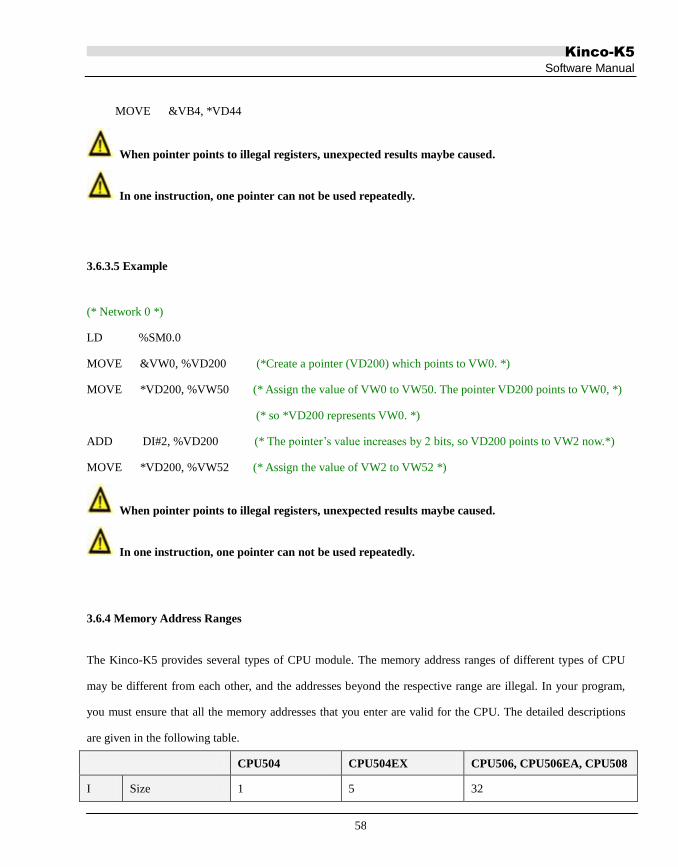
Kinco-K5
Software Manual
58
MOVE &VB4, *VD44
When pointer points to illegal registers, unexpected results maybe caused.
In one instruction, one pointer can not be used repeatedly.
3.6.3.5 Example
(* Network 0 *)
LD %SM0.0
MOVE &VW0, %VD200 (*Create a pointer (VD200) which points to VW0. *)
MOVE *VD200, %VW50 (* Assign the value of VW0 to VW50. The pointer VD200 points to VW0, *)
(* so *VD200 represents VW0. *)
ADD DI#2, %VD200 (* The pointer‟s value increases by 2 bits, so VD200 points to VW2 now.*)
MOVE *VD200, %VW52 (* Assign the value of VW2 to VW52 *)
When pointer points to illegal registers, unexpected results maybe caused.
In one instruction, one pointer can not be used repeatedly.
3.6.4 Memory Address Ranges
The Kinco-K5 provides several types of CPU module. The memory address ranges of different types of CPU
may be different from each other, and the addresses beyond the respective range are illegal. In your program,
you must ensure that all the memory addresses that you enter are valid for the CPU. The detailed descriptions
are given in the following table.
CPU504 CPU504EX CPU506, CPU506EA, CPU508
I Size 1 5 32

Kinco-K5
Software Manual
59
Bit address %I0.0 --- %I0.7 %I0.0 --- %I4.7 %I0.0 --- %I31.7
Byte address %IB0, IB1 %IB0 --- %IB4 %IB0 --- %IB31
Word address %IW0 %IW0 --- %IW2 %IW0 ---% IW30
Double-word
address ――― %ID0 %ID0 --- %ID28
Q
Size 1 5 32
Bit address %Q0.0 --- %Q0.7 %Q0.0 --- %Q4.7 %Q31.0 --- %Q31.7
Byte address %QB0 %QB0 --- %QB4 %QB0 --- %QB31
Word address ――― %QW0 --- %QW2 %QW0 --- %QW30
Double-word
address ――― %QD0 %QD0 --- %QD28
AI Size 0 16 64
Word address ――― %AIW0 --- %AIW14 %AIW0 --- %AIW62
AQ
Size 0 16 64
Word address ――― %AQW0
-- %AQW14
%AQW0 -- %AQW62
HC Size 8
Word address %HC0,%HC1
V
Size 4096
Bit address %V0.0 ---%V4095.7
Byte address %VB0 --- %VB4095
Word address %VW0 --- %VW4094
Double-word
address
%VD0 --- %VD4092
%VR0 --- %VR4092
M
REAL address 1024
Size %M0.0 --- %M1023.7
Bit address %MB0 --- %MB1023

Kinco-K5
Software Manual
60
Byte address %MW0 --- %MW1022
Word address %MD0 --- %MD1020
SM
Double-word
address
300
Size %SM0.0 --- %SM299.7
Bit address %SMB0 --- %SMB299
Byte address %SMW0 --- %SMW298
Word address %SMD0 --- %SMD296
L
Double-word
address
272
Size %L0.0 --- %L271.7
Bit address %LB0 --- %LB271
Byte address %LW0 --- %LW270
Word address %LD0 --- %LD268
Table 3-5 CPU Memory Ranges
3.6.5 Function Block and Function Block Instance
3.6.5.1 Standard Function Blocks in IEC61131-3
Timers: TP --- Pulse timer; TON --- On-delay timer; TOF --- Off-delay timer
Counters: CTU --- Up-counter; CTD --- Down-counter; CTUD --- Up-Down counter
Bistable elements: SR --- Set dominant; RS --- Ret dominant
Edge detection: R_TRIG --- Rising edge detector; F_TRIG --- Falling edge detector
3.6.5.2 Instances of Function Blocks
“Instantiation of FBs” is a very important concept in IEC61131-3.
Instantiation means that the programer declares and creates a variable by specifying its name and data type.

Kinco-K5
Software Manual
61
After instantiation, the variable can be accessed in the program.
FB also needs to be instantiated as a variable does. After instantiation, a FB (as an instance) can be used in the
POU in which it is declared.
As shown in the following graph, only T1 can be called and accessed.
Data is an instance of INT type, and T1 is an instance of TON.
FB Instance Name FB Type
Variable Name Data Type
Data INT :
T1 TON :
3.6.5.3 FB Instance Memory Areas
A fixed memory area is allocated for each type of FB to store its instances in the Kinco-K5 PLC, and the details
are shown in the following table.
T
Description Timer Memory Area, where instances of TON, TOF and TP can be allocated.
It‟s used to store the status bits and current values of all the timer instances.
Access mode Directly access the status bit and current value of a timer instance
Access right Read only
Others Cannot be retentive, and cannot be forced
C
Description Counter Memory Area, where the instances of CTU, CTD and CTUD can be allocated.
It‟s used to store the status bits and current values of all the counter instances.
Access mode Directly access the status bit and current value of a counter instance

Kinco-K5
Software Manual
62
Access right Read-only
Others Can be retentive, and cannot be forced
RS
Description RS the trigger Area, where instances of RS can be allocated.
It‟s used for storing the status bits for all the RS instances.
Access Mode Directly access the status of the RS instances
Access Rights Read-only
Others Cannot be retentive, and cannot be forced
SR
Description SR the trigger Area, where instances of SR can be allocated.
It‟s used for storing the status for all the SR instances.
Access Mode Directly access the status bit of the SR instances
Access Rights Read-only
Others Cannot be retentive, and cannot be forced
Table 3-6 FB Instance Memory Areas
3.6.6 Using FB Instances
A FB instance must be declared before it is used.
For the convenience of users, KincoBuilder complies with the following rules: the representation of FB
instances accords with the traditional PLC, e.g. T0, C3; you just need to call the valid FB instances of the
desired types in your program, and KincoBuilder will generate the declarations automatically in the Global
Variable Table.
T
Format Tx
Description x: a decimal digit, indicating the timer number.

Kinco-K5
Software Manual
63
Data type
BOOL --- status bit of the timer
INT --- current value of the timer
Tx is used to access both of the two variables. KincoBuilder will identify access to
either the status bit or the current value according to the instruction used:
instructions with BOOL operands access the status bit, but instructions with INT
operands access the current value.
Example T0 T5 T20
C
Format Cx
Description x: a decimal digit, indicating the counter number.
Data type
BOOL --- status bit of the counter
INT --- current counting value of the counter
Cx is used to access both of the two variables. KincoBuilder will identify access to
either the status bit or the current value according to the instruction used:
instructions with BOOL operands access the status bit, but instructions with INT
operands access the current value.
Example C0 C5 C20
RS
Format RSx
Description x: a decimal digit, indicating the RS Bistable number.
Data Types BOOL --- the status of the RS Bistable
Example RS0, RS5, RS10
SR
Format SRx
Description x: a decimal digit, indicating the SR Bistable number.
Data Types BOOL --- the status of the SR Bistable
Example SR0, SR5, SR10

Kinco-K5
Software Manual
64
3.6.7 FB Instances Memory Ranges
The size of the memory area that the PLC can allocate to a type of FB instances is limited by the resource of the
hardware; therefore, each type of Kinco-K5 CPU allocates a different memory range for the FB instances. The
detailed descriptions are given in the following table.
T
Amount 256
Range T0 --- T255
Resolution
T0 --- T3:1ms
T4 --- T19:10ms
T20 --- T255:100ms
Max timing 32767* Resolution
C
Amount 256
Range C0 --- C255
Max counting value 32767
RS Amount 32
Range RS0 --- RS31
SR Amount 32
Range SR0 --- SR31
Table 3-7 FB Instances Memory Ranges

Kinco-K5
Software Manual
65
Chapter IV How to Use KincoBuilder … Basic Functions
This chapter describes the components of KincoBuilder detailedly, including their functions and operating steps.
Based on the basic concepts in the previous chapters, this chapter can help you get a further and comprehensive
understanding of KincoBuilder.
LD editor and IL editor may involve IEC61131-3 grammar, which will be introduced in the next chapter.
4.1 Configuring General Software Options
You need to configure some general options for KincoBuilder, e.g. the default programming language and the
default CPU type for new projects. KincoBuilder will save your configuration automatically, so you just need
configure them once before the next modification
Select the [Tools]>[Options…] menu command, and then the following dialogue box will popup:
① General Tab
Figure 4-1 The “Options” Dialog Box

Kinco-K5
Software Manual
66
Defaults
• Programming Language:
Choose the default programming language for new programs, IL or LD.
• CPU Type for New Projects:
Choose the CPU type that new projects always default to use.
Integer Format While Monitoring
Choose the display format for the integer values while monitoring.
Mixed: The INT and DINT values are displayed in decimal format;
In addition, the BYTE, WORD and DWORD values are displayed in hexadecimal format.
DEC: All the integer values are displayed in decimal format.
HEX: All the integer values are displayed in hexadecimal format.
Others
• Record log:
If this is checked, KincoBuilder will create a sub-directory named “KincoPlcLog” in its installation directory.
Kincobuilder will create a log file for each time, and it only retain the day‟s files.
These log files is helpful for us to track and solve bugs of Kincobuilder.
• Open RS232 for synchronous I/O:
Sometime Kincobuilder maybe fail to communicate with PLC while using some USB to RS232 convertors.
This problem is caused by the compatibility of the convertor‟s driver.
Checking this checkbox maybe helpful, and in most cases it can solve this problem.
② Cross Reference Options

Kinco-K5
Software Manual
67
After compilation, all the used parameters and the locations will be displayed in the Cross Reference table.
All the used parameters will be displayed by default in Kincobuilder.
In this page, user could select [Memory Type] and [Data Type] to be displayed in the Cross Reference table.
As defined in the above picture, only bit registers of M area will be displayed in the Cross Reference table.

Kinco-K5
Software Manual
68
4.2 About Docking Windows
In KincoBuilder, Workspace/Instructions/HW Catalog/Information Output windows are designed as floating
windows. These floating windows have two display modes: floating mode and dock mode. In floating mode, a
window can appear anywhere on your screen. In dock mode, a window is fixed to a dock along any of the four
borders of the main KincoBuilder window.
To change a dock window to a floating window
Double-click in the window border.
Point to the title bar and drag the window out of its dock area.
To dock a floating window
Double-click the window title bar to return the window to its previous docked location.
Point to the title bar and drag the window to a dock area.
To switch a docking window to auto-hide mode
Click the icon located on the top-right corner of the window.
In auto-hide mode, it shall hide automatically and shrink into an icon and stay at the border of the main
KincoBuilder window; Point to this icon for a moment, the window shall appear.
To cancel the auto-hide mode of a docking window
Click the icon to return the window to its previous docked location.

Kinco-K5
Software Manual
69
4.3 Configuring Hardware
In a project, you are recommended to finish configuring hardware at first. When a new project has been created,
a default CPU assigned in the “Options” dialog box shall be added automatically and you can modify it at will.
KincoBuilder provides you with a complete, flexible and convenient hardware configuration environment
where you can configure all the parameters for each PLC module. The “Hardware” window is shown as Figure
4-2. We can see that this window is composed of two parts:
Figure 4-2 the Hardware Window
The Configuration Table
The upper part of the hardware window shows a detailed list of the PLC modules in table form, and we call it
Configuration Table. The Configuration Table represents the real configuration: you arrange your modules in
the Configuration Table just as you do in a real control system.
The Parameters Window

Kinco-K5
Software Manual
70
The lower part of the hardware window shows all the parameters of the selected module in the Configuration
Table, and we call it Parameters Window.
4.3.1 How to open the Hardware window
You can open the “Hardware” window by using one of the following ways:
Double-click the [Hardware] node in the Manager window.
Right-click the [Hardware] node, and then select the [Open] command on the pop-up menu.
4.3.2 Copy and paste the hardware configuration in different projects
In Kincobuilder, users are allowed to copy and paste [Hardware Configuration] in different projects. The
[Hardware Configuration] refers to configuration of of CANOpen, communication port, etc. and will not copy
the information of CPU, which means it can be executed between CPUs. All pending projects must be opened
by KincoBuilder. You may use the copy and paste function the same time with that of LD or IL.
This function will be helpful if you would like to transplant the configuration of CANOpen of old projects.
You may use this function as follows:
Click [Copy Hardware Configuration], [Paste Hardware Configuration] in the [Edit] menu;
Right-click [PLC Hardware Configuration] in the [Project Manager] tree and execute [Copy
Hardware Configuration] and [Paste Hardware Configuration]
4.3.3 Add/Remove Modules
Add a module
You can add a module using the following steps:
In the Configuration Table, click a row to place the focus on it. If there exists a module in this row, it must
be removed before adding a new module.

Kinco-K5
Software Manual
71
In the PLC Catalog Window, double-click a module to add it to the row with the current focus in the
Configuration Table.
Row 1 can only be added into with a CPU module, and other rows can only be added into with the expansion
modules. There shall not be any null rows between each two modules. If a null row exists, KincoBuilder will
not allow continuing to add modules after it, and an error message-box will popup when saving or compiling
the project.
Remove a module
You can remove a module by using the following ways:
Click the module to be removed in the Configuration Table, then use Del key to remove it.
Right-click the module to be removed, and then select the [Remove] command on the pop-up menu.
4.3.4 Configuring Module Parameters
Once you have arranged your modules in the Configuration Table, you can continue to assign their parameters.
KincoBuilder allows you define all of the parameters of a module.
In the Configuration Table, click a PLC module to place the focus on it, and then the Parameters Window of this
module shall appear below. You can assign a module‟s parameters in its Parameters Window. Of course, you can
use Up and Down arrow key to move the focus in the Configuration Table
On the right hand of the Parameters Window, there are two public buttons: 【Default】 and【Cancel】.
【Default】: If you click this button, KincoBuilder will assign default parameters for the current module.
【Cancel】: If you click this button, the original configuration of the current module will be restored.
Notice: The addresses of the modules in the same memory area (I, Q, AI or AQ) cannot overlap!

Kinco-K5
Software Manual
72
4.3.4.1 Parameters of the CPU
① 【I/O Configuration】 tab
Here you can assign the I/O parameters of the CPU module, as shown in the following figure.
Figure 4-3 I/O Parameters of the CPU
Input: Here, you can configure the DI channels on the CPU body.
I Address: the start byte address of the DI channels in I area. It is fixed to be 0.
Input Filters: Select an input filter (ms) that defines a delay time for DI channels. This delay is helpful
to filter the input noise and enhance the anti-interference capacity of the control system. When an input
state changes, it won‟t be accepted as valid unless it remains for the duration of the filter time.
Output: Here, you can configure the DO channels on the CPU body.
Q Address: the start byte address of the DO channels in Q area. It is fixed to be 0.
Output States while STOP: Set the digital outputs in a known state while the CPU stops. If the
checkbox for an output is checked, the output shall be set to ON (1) while the CPU stops. The default
state of a output while the CPU stops is OFF (0). This function is very significant for safety interlock
requirements after a RUN-to-STOP transition.
② 【Communication Ports】tab

Kinco-K5
Software Manual
73
Here you can assign the serial communication parameters for Port0, Port1 and Port2 on the CPU module.
Figure 4-4 Serial Communication Parameters
Port0
Address: Choose the desired station address of Port0. This address also acts as a Modbus RTU slave
number, and it is must be exclusive in the network.
Baudrate: Select the desired baud rate. (1200, 2400, 4800, 9600, 19200, 38400, 57600or115200bps)
Parity: Select the desired parity scheme. (No parity, Odd, or Even)
DataBits: Select the number of bits in the bytes transmitted and received. (8)
StopBits: Select the number of stop bits. (1)
Port1 and Port2
Port1 and Port2 are RS485 ports.
Modbus Master: If the checkbox is checked, Port1 will work as a Modbus RTU master.
Timeout: Enter a timeout value for this Modbus master.
Retry: Enter the value of retry times. When the master receives a wrong frame from a slave, it will retry
to communicate with the slave for „Retry’ times.
Baudrate: Select the desired baud rate. (1200, 2400, 4800, 9600, 19200or38400bps)
Parity: Select the desired parity scheme. (No parity, Odd, or Even)
DataBits: Select the number of bits in the bytes transmitted and received. (8)
StopBits: Select the number of stop bits. (1)

Kinco-K5
Software Manual
74
When the master station sends out a command, it will report communication errors under the following
conditions:
A communication timeout error will be reported if there is no response received from slave in the defined
time.
If fault response received by master station, then it will try resend commands again. User set the retry times.
If master station still does not receive correct response for last time retry, master station will wait for the set
timeout time then report a communication timeout error.
③ 【Retentive Ranges】 tab
Here you can define four retentive ranges to select the ranges of the RAM you want to retain on power loss. If
the CPU loses power, the instantaneous data in the RAM will be maintained by internal battery, and only the
data in the retentive ranges will be left unchanged at next power on.
NOTE: The memory area of “Initial Data”, “Data Maintain” and “Data Backup” should be placed to
avoid overlap. The data should be recovered after CPU powered on. The sequence is: recover the memory
data defined in “Data Maintain”, assign initial value to the memory are of “Initial Data” and recover the
data permanently saved by commands.
Figure 4-5 Retentive Ranges
There are 4 separate Retentive areas configurable in all.

Kinco-K5
Software Manual
75
• Data area
Select the memory area for retentive Range 1. (V area or Counter area)
For counters, only the current count values can be retentive.
• Start
Assign the start byte address.
• Length
Assign the length, unit: byte.
As shown in Figure 4-5, the data stored in Range 1 (%VB0 to %VB9), Range 2 (%VB100 to %VB199), Range
3 (C0 to C9) and Range 4 (C20 to C49) will be retentive on power loss.
④ 【Local AI/AO】 tab
K506EA-30AT integrates 4 AI channels. The channels are mapped to AIW0, AIW2, AIW4, AIW6 respectively.
Sampling conversion speed of each channel is about 30times per second.
K506EA also integrates 2 AO channels. The channels are mapped to AQW0, AQW2 respectively.
Sampling conversion speed of each channel is about 30times per second.
For these integrated AI/AO, users have to set functions and filter for each channel in
[Hardware]-[Local AI]/[Local AO] tab as follows:

Kinco-K5
Software Manual
76
⑤ CANOpen tab
See Appendix F.
⑥ Others tab
1. If not check “Permanent backup VB3648-4095”, the K5 PLCs will permanent backup 255
bytes (VB3648-3902) by default which is the same with K3 PLC.
User could check “Permanent backup VB3648-4095” according to the program.
2.Backup the project files.
When users new create a project, [Backup the project files(Not support for K504)] is checked by
default. By this function, the project programmed by Kincobuilder will be embedded in the OBJ file
in ZIP format. When user uploads project, the project will be extracted from the ZIP file.
•Comparing with K3 upload function, notes parameter identifier, program name subroutine
name will be saved.
• Backup the project files will occupy EEPROM memories. If the project is too big to be
compressed in EEPROM, PLC will ignore this option. The upload function is the same with K3
by default.
• To check this option, it will increase the time for download.
• If user does not need to upload PLC project, just for debugging project, then users could
uncheck this option.

Kinco-K5
Software Manual
77
4.3.4.2 Parameters of the DI Module
You can set the parameters of a DI module as follows:
Figure 4-6 Parameters of the DI Module
Address
• Start
Enter the start byte address of the address range of this module in I area. The addresses for this module‟s
channels are based on this start address.

Kinco-K5
Software Manual
78
• Length
Assign the length. This value is fixed, and it depends on the number of this module‟s DI channels.
As shown in Figure 4-6, the module has 8 DI channels, and its start address is %IB2, so the addresses of its
channels are %I2.0 to %I2.7.
4.3.4.3 Parameters of the DO Module
Figure 4-7 Parameters of the DO Module
Address
• Start
Enter the start byte address of the address range of this module in Q area. The addresses for this module‟s
channels are based on this start address.
• Length
Assign the length. This value is fixed, and it depends on the number of this module‟s DO channels.
As shown in Figure 4-7, the module has 16 DO channels, and its start address is %QB2, so the addresses of its
channels are %Q2.0 to %Q3.7.
Output States while STOP
Here you can set the digital outputs in a known state while the CPU stops. If the checkbox for an output is
checked, the output shall be set to ON (1) while the CPU stops. The default state of the output is 0 while the
CPU is in STOP.

Kinco-K5
Software Manual
79
4.3.4.4 Parameters of the AI Module
Figure 4-8 Parameters of the AI Module
Address
• Address
Enter the start byte address (address of the first channel) of this module in AI area; the addresses for the other
channels are based on this start address, each address occupies two bytes. This numerical value must be even.
• Length
Assign the length. This value is fixed, and it depends on the number of this module‟s AI channels.
As shown in Figure 4-8, the module has 4 AI channels, and its start address is %AIW0, so the addresses of the
other channels are %AIW2, %AIW4 and %AIW6.
Inputs
• Function
Select a measurement type for a channel, e.g. 4-20mA, 1-5V, etc.
Please refer to 6.1.4 Internal Presentation Format of the Measured Values of Signals in “Hardware Manual” for

Kinco-K5
Software Manual
80
the representation of the measured value.
• Filter
Select a software filter for a channel. As for the analogue signal with rapid changes, a filter can be helpful to
stabilize the measured value.
Notice: If the control system requires responding to an AI signal quickly, the software filter of the
corresponding channel should be disabled.
You can assign one of the following filters for a channel:
None --- The software filter is disabled.
Arithmetic Mean --- The filtered value is the arithmetic mean value of a number of samples of the input.
Median Average --- The filtered value is the sliding mean value of a number of samples of the input.
4.3.4.5 Parameters of the AO Module
Figure 4-9 Parameters of the AO Module
Address
• Address
Enter the start address (address of the first channel) of this module in AQ area; the addresses for the other

Kinco-K5
Software Manual
81
channels are based on this start address, each address occupies two bytes. This numerical value must be even.
• Length
Assign the length. This value is fixed, and it depends on the number of this module‟s AO channels.
As shown in Figure 4-9, the module has 2 AQ channels, and its start address is %AQW0, so the address of
another channel is %AQW2.
Outputs
• Function
Select a type of output signal for a channel, e.g. 4-20mA, 1-5V, etc.
Please refer to 7.1.4 Internal Presentation Format of Signal Value in “Hardware Manual” for the representation of
the output value.
• Freeze Output while STOP
Select whether to set the analog output to a known value (Freeze Value) while the CPU stops. If the checkbox
for an output is checked, the output shall keep at the freeze value while the CPU stops.
• Freeze Value
Here you can enter a value which the analog output shall keep at while the CPU stops.

Kinco-K5
Software Manual
82
4.4 The Initial Data Table
In the Initial Data Table, you can assign initial numerical values for BYTE, WORD, DWORD, INT, DINT and
REAL variables in V area. The CPU module processes the Initial Data once at power on and then starts the scan
cycle. The Initial Data Table is as Figure 4-10.
Figure 4-10 the Initial Data Table
NOTE: The memory area of “Initial Data”, “Data Maintain” and “Data Backup” should be placed to
avoid overlap. The data should be recovered after CPU powered on. The sequence is: recover the memory
data defined in “Data Maintain”, assign initial value to the memory are of “Initial Data” and recover the
data permanently saved by commands.
4.4.1 Opening the Initial Data Table
Double-click the [Initial Data] node in the Manager window.
Right-click the [Initial Data] node, and then select the [Open] command on the pop-up menu.
4.4.2 Editing a Cell
Click on a cell to make it change to the editing mode, and now you can type the desired data. Besides, you can
use the UP, DOWN, LEFT and RIGHT arrow keys to move the focus from one cell to another, and the cell
that gets the focus shall change to the editing mode.
When a cell loses focus, its contents are confirmed. Besides, you can use the ENTER key to confirm your work
and move the focus to the next cell.

Kinco-K5
Software Manual
83
The illegal data shall turn red.
4.4.3 Making Initial Data Assignments
The table has 5 columns: an Address column and 4 Value columns.
Enter a direct variable, i.e. a direct address in the Address column.
Enter numerical values in the Value columns. You can enter one value or multiple values. If you enter
multiple values, KincoBuilder shall make an implicit address assignment.
As shown in Figure 4-10, Row 1 indicates that B#1 is assigned to %VB0, B#11 is assigned %VB1 and B#11 is
assigned %VB2; Row 2 indicates that 2, 22 and 222 are assigned to %VW12, %VW14
and %VW16respectively; Row 3 indicates that DI#3, DI#33 and DI#3333333 are assigned
to %VD122, %VD126 and %VD130 respectively.
4.4.4 Editing the Initial Data Table
Sorting
Click the Address column header to sort the table.
The Pop-up Menu
Right-click on any cell in the table, the following menu will popup:
• Delete Row: Delete the row in which the focus is located.
• Insert Row (Above): Insert a new blank row above the row in which the focus is located.
• Insert Row (Below): Insert a new blank row below the row in which the focus is located.

Kinco-K5
Software Manual
84
Please pay attention when using the paste command: it will not work between different types of table‟ neither
between different rows.

Kinco-K5
Software Manual
85
4.5 The Global Variable Table
The Global Variable Table is composed of two parts: the Global Variable tab and the FB Instance tab.
The Global Variable tab
It can be used to define the Global Variable, which accesses PLC memory address.
The Global Variable in the program can replace PLC memory address to ensure the readability of the program.
Each memory address can be assigned one symbolic variable name; similarly, one symbolic variable name will
have one corresponding memory address only.
Please refer to 3.3.1 How to define an identifier to see the defining rule;
Please refer to 3.5 Variables to see more information about the global variables.
You can declare global symbolic variables here, as shown in Figure 4-11.
In this manual, “the Global Variable Table” usually indicates this tab.
Figure 4-11 the Global Variable tab

Kinco-K5
Software Manual
86
The FB Instance tab
Figure 4-12 the FB Instance tab
As mentioned in 3.6.6 Using of FB Instances, the FB instances are declared by KincoBuilder automatically to
facilitate the users. So all the information here is only for reference and you cannot modify them.
4.5.1 Opening the Global Variable Table
There are three ways to open the Global Variable Table:
Double-click the [Global Variable] node in the Manager window.
Right-click the [Global Variable] node, and then select the [Open] command on the pop-up menu.
Select the [Project]→[Global Variable] menu command.
4.5.2 Declaring the Global Variables
The table has 4 columns: Symbol, Address, Data Type and Comment.

Kinco-K5
Software Manual
87
Open the Global Variable Table window and select the Global Variable tab.
Enter the symbol name in the Symbol column and confirm it.
Enter the direct address in the Address column and confirm it.
Choose a data type from the drop list in the Data Type column.
(Optional) Enter a Comment.
If you declare a global variable in the Global Variable Table, you can use it in any POU, and a direct address is
equivalent to its symbolic name in the user program.
Please refer to 3.5 Variables for more information about the global variable.
You can operate the Global Variable Table just as the Initial Data Table. Please refer to 4.4 The Initial_Data
Table for more information.

Kinco-K5
Software Manual
88
4.6 The Cross Reference Table
The Cross Reference Table shows all the variables used in the project, and identifies the POU, network or line
location, and how to access the operands (read or write to). The Cross Reference Table is helpful when you
want to know if a symbolic name or an address is already in use, and where it is used.
Information in the Cross Reference Table only be generated after the first compilation, and will refresh
automatically after each compilation.
The Cross Reference Table is as the following figure:
Figure 4-13 the Cross Reference Table
• Address Display all the memory addresses used in the project.
• Symbol Display the global symbolic name of the Address.
• POU Indicate the POU where the Address is used.
• Position Indicate the line or network where the Address is used.
• Read/Write Indicate whether the Address is read or written to here.
As shown in Figure 4-13, the first row in the table indicates that %AIW0 is used once in Network 0 of the
Main program, and it is read this time.
Double-click on a row in the Cross Reference Table, and you shall go to the corresponding part of your program.
4.6.1 Opening the Cross Reference Table
Select the [Project]→[Cross Reference] menu command.
Click the icon in the toolbar.

Kinco-K5
Software Manual
89
Use the Alt+C shortcut key.
4.6.2 The Pop-up Menu
Right-click on any row in the table, the following menu shall popup.
• Refresh: Refresh the table and display the latest cross-reference information.
• Go to: Go to the corresponding part of your program.
Parameter locating
Double click on one row to enter the POU and locate on the specified parameter.
Filter: Enter [Tools]-[Options]-[Cross Reference Options], then user could select “Memory Type” and
“Data Type” to be displayed.

Kinco-K5
Software Manual
90
4.7 The Status Chart
You can use the Status Chart to monitor and force any direct variable used in the project after you have
downloaded the project to the PLC. The Status Chart is shown as Figure 4-14.
Memory Monitor Chart
Can be used to detect any memory address of PLC;
This function is available on K3 and K5 PLC; on K5 all memories are available while on K3 only I, Q, AI, AQ,
M, V areas.
The Monitor Chart is shown as follows:
The Status Chart
Figure 4-14 the Status Chart
You may find in the chart:
[Memory Address]: Input the initial address of the memory area to be detected;
[Monitor Length]: Input the total number of data to be detected from the memory addresses. Maximum
number is 150.
For each row maximum number of data shown is 3. If more than 3, data will be separate into different rows.

Kinco-K5
Software Manual
91
[Display Format]: Select the display format, including decimal and hexadecimal system.
[Memory Value]: Show the monitoring memory value.
If the monitoring is bit memory, only the TRUE or FALSE will be shown.
• Address Enter the initial address to be monitored and forced.
• Symbol Display the global symbolic name of the Address.
• Format Choose a display format for the current value and new value.
(BOOL; REAL; Signed, Unsigned, Hexadecimal or Binary)
• Current value Display current values of the Address from the PLC.
• New Value Enter the value to be forced for the Address when monitoring
You can open a Status Chart to edit it, but no status information is displayed in the Current Value column
unless you select the [Monitor] command from the [Debug] menu or toolbar.
In order to be efficient, KincoBuilder only allows monitoring and forcing the variables used in the project. If
you enter the variables that are not used, the Current Value and New Value won‟t take effect.

Kinco-K5
Software Manual
92
4.7.1 Opening the Status Chart
Double-click the [Status Chart] node in the Manager window.
Right-click the [Status Chart] node, and then select the [Open] on the pop-up menu.
Select the [Debug] →[Status Chart] menu command.
4.7.2 Monitoring the Variable Value
You may monitor the variable value by Status Chart as follows:
Input the memory address to be monitored in [Address]
Enter into online monitoring status via following means:
Execute [Debug]→[Online Monitor] command;
Click the icon on the toolbar;
Use shortkey F6
[Display Format] of the monitor value can be changed at any time.
4.7.3 The Force Function
You can use the Force Function to edit the variable value in I area, Q area, M area, V area, AI are, AQ area,
among which variables in I area, Q area, M area and V area can be forced by bit, byte, word or double byte;
variables in AI area and AQ area can be forced by word. When CPU is rebooted, all force status will be
canceled.
K5 allows maximum 32 variables. Immediate commands cannot be forced.
In at certain time of the scanning period, one variable may have following possibilities: exterior input signal (I,
AI) or user program result (Q, AQ, M, V). Variable valuing principles are as follows:
Variables in M area and V area, force value has the same priority of the program execution result.
Variables in I and AI area, force value is prior to exterior signal input value.
Variables in Q and AQ area, program execution result will overwhelm.

Kinco-K5
Software Manual
93
4.7.4 Right-click Menu
Force: Input [Force Value] the direct memory (address) of PLC.
Cancel Force: Cancel the Force status of single being clicked.
Force All: Input all forced value of [Force Values] to the corresponding direct memories (address) of PLC.
All Cancel Force: Cancel all the Force status.
Read All Forced: Read all forced variables and show them in the Variable Status Table.
4.7.5 Force and Cancel Force
You may force or cancel force a variable in the Variable Status Table as follows:
Input the direct memory address to be forced in [Address];
Select the [Display Format] of the value and you may verify it at any time (optional);
Input the force value. You may input a round number in decimal and Kincobuilder will adjust it
accordingly;
You may force a variable as follows:
Right-click the row and execute [Force] command;
Click the row and click icon in the tool bar;
Click the row and execute [Debug] → [Force] command;

Kinco-K5
Software Manual
94
You may cancel forcing a direct [Address] in a row as follows:
Right-click the row and execute [Cancel Force] command;
Click the row and click the icon in the toolbar
Click the row and execute [Debug] → [Cancel Force]
The edition of Variable Status Table is the same as Initial Data, please refer to that part.

Kinco-K5
Software Manual
95
4.8 Password Protection
The Kinco-K5 provides password protection for you to encrypt the CPU for restricting access to specific
functions. A password is a string of letters, digits, and underline characters, and it is case-sensitive. The length
of a password is 8-14 characters.
If a CPU is encrypted, the password will be required to enter when you try to access the restricted functions.
Here, if a correct password is entered, the CPU will permit the corresponding operation; if a wrong password is
entered, the CPU will refuse the corresponding operation. The password is only valid for current operation. If
you try to access the restricted functions again, then you have to enter the password again.
K5 limits the number of password input times. When you enter a wrong password for limited number of times,
you must restart the PLC to continue the operation that needs a password.
If you set the PLC protection level to be “Level 3: Minimum access” or enable [Upload Disabled] choice when
downloading project, the user program will be encrypted and saved in cipher text in the PLC.
4.8.1 Protection Privileges
The Kinco-K5 provides the following 3 protection privileges:
Level 1: Full access. No restriction to access all the functions. This is the default level.
Level 2: Partial access. Password is required while downloading.
Level 3: Minimum access. Password is required while downloading and uploading.
4.8.2 How to change the password and the protection level
Select [PLC] →[Password…] menu command to open the 'Password' window. See the following figure:

Kinco-K5
Software Manual
96
Figure 4-15 the 'Password' Window
Old password
If the connected CPU has been set with password protection, then the original old passwords has to be entered
here for verification. If no password protection has ever been set, then just leave the edit box empty.
New Privileges
Here, you can set the new protection levels and passwords for the connected CPU.
New Privileges: You can choose any one from level 1, level 2, and level 3.
New password: You can enter a new password here.
Confirm: You need to enter the new password again here.
After finishing the settings above, you can click on the [Apply] button to write the new settings into the
connected CPU, and then the new settings will be efficient.

Kinco-K5
Software Manual
97
4.8.3 How to recover from a lost password
If you forget the password, you have to clear the memory of the CPU for continuing to use it. Select [PLC] →
[Clear…] menu command to clear the memory of the CPU.
After clearing, all the data in the CPU, including the user program, the configuration data, and the password,
will be lost, and the CPU is restored to the factory-set defaults, except for the RTC. Here, the communication
parameters are the following: the station number 1, the baudrate is 9600, no parity, data 8 bits, stop 1 bit.
Password can not be cleared separately.

Kinco-K5
Software Manual
98
Chapter V How to Use KincoBuilder … Programming
KincoBuilder presently supports IL and LD programming languages, and so two editors are provided for
programming: the IL editor and the LD editor. This chapter will detailedly describes the two editors and
meanwhile represents the relevant syntaxes and rules of IL and LD languages.
IEC61131-3 defines three textual languages and three graphical languages. The textual languages include:
Instruction List (IL), Structured Text (ST) and Sequential Function Chart (SFC, textual version); and the
graphical languages include: Ladder Diagram (LD), Function Block Diagram (FBD) and Sequential Function
Chart (SFC, graphical version).
KincoBuilder presently provides two editors for programming: the IL editor and the LD editor. You can write a
POU in IL or LD language, i.e. you can write a POU with the IL or LD editor. With some restrictions, a POU
written in a program editor can be viewed and modified in another program editor. You just select the [Project]→
[IL] or [Project]→[LD] menu command to switch the editor for the current POU.
5.1 Programming in IL
5.1.1 Overview
IL is a low level language that is very similar with the assembly language, and it is based on similar instruction
list languages from well-known PLC manufacturers around the world.
IL is close to a machine code, and so it is an efficient language. IL is very appropriate for experienced
programrs. Sometimes you can use IL to solve the problems that you cannot solve easily using LD.

Kinco-K5
Software Manual
99
5.1.2 Rules
5.1.2.1 Instructions
IL is a line-oriented language. An IL program consists of a sequence of instructions. Each instruction shall begin
on a new line and contains an operator. Operands are optional, and they are separated by commas or spaces. A
comment can be entered at the end of the line using parentheses and asterisks. Blank lines are allowable in an
instruction list.
The following figure shows the typical format of an IL statement:
label:
Operator Operands (* Comment *)
Figure 5-1 The Typical Format of an IL Statement
label
Optional. Jump is used to jump to a line of the IL program. In this case, a label in front of the destination line is
used. The name format of a label is identical with that of an identifier.
Operator
PLC instruction.
Operands
Please refer to instructions set for the detailed descriptions.
Comment
Optional, Only one comment is allowable in a line; nesting is not permitted.
The following is an example:
(* NETWORK 0 *)
begin: (* a label, used at jump *)
LD %I1.0
TP T2, 168 (* if %I1.0 is true, the timer T2 is started. T2 is an instance of TP. *)

Kinco-K5
Software Manual
100
5.1.2.2 Current Result
IL provides a universal accumulator called the “Current Result (CR)”, and the current result of logical operation
is stored in the CR. The CR will be refreshed after the execution of each statement, and it may act as the
execution condition or one of the operands for the next statement.
All the operators in KincoBuilder can be grouped according to their influence on the CR as shown in the
following table. Please refer to the instruction set for further details.
Group Influence on the CR Examples
C Create the CR LD, LDN
P Set the CR to be the result of operation Bit logic, Compare instructions, etc.
U Leave the CR unchanged ST, R, S, JMP, JMPCN, JMPC, etc.
Table 5-1 The Operator Groups
IEC61131-3 does not define the above groups. As a result, these groups in different programming
systems may be different.
5.1.2.3 Network
In KincoBuilder, a POU is composed of the following parts:
POU type and POU name
Variable declaration part
Code part containing the instructions
Network can be taken as the basic code segment; the code part of the POU is composed of several networks.
Networks make it easier to view an IL program. A typical network includes:
Network label
Network comment.
Instructions

Kinco-K5
Software Manual
101
5.1.3 The IL Editor in KincoBuilder
When a new program in IL language is being established, the IL editor will be ready for programming; if an IL
program is opening, the IL editor will also be ready. The IL editor is shown as follows.
Figure 5-2 the IL Editor
The IL editor is composed of two parts:
• The Variable Table: you can declare the local variables and input/output parameters of the POU here.
• The Program Editor: you can edit your control program here.
5.1.3.1 Adding a Network
Use one of the following ways to add a network:
Use Ctrl+Q shortcut key

Kinco-K5
Software Manual
102
Right-click the Program Editor and select the [Insert Network] on the pop-up menu.
5.1.3.2 Allowable Instructions Format in a Network
There can be only one statement label in a network. For example:
(* NETWORK 0 *)
MRun: (* There can be only one statement label *)
A network can contain some statements.
In 5.2.2.2 Current Result , we divide all the instructions three groups (“C”, “P” and “U”).
The network must begin with one of the instructions in group “C”, and end with one of the instructions in group
“P” or “U”. For example:
(* NETWORK 0 *)
LD %M3.5 (*Begin with LD instruction *)
… … (*you can enter other instructions *)
ST %Q2.3 (*End with the allowable instruction *)
A network can contain some statement labels and some statements.
The network must begin with a label or one of the instructions in group “C”, and end with one of the
instructions in group “P” or “U”. For example:
(* NETWORK 0 *)
MRun:
LD %M3.5 (*Begin with LD instruction *)
… … (*You can enter other instructions*)
ST %Q2.3 (*End with the allowable instruction *)

Kinco-K5
Software Manual
103
5.1.3.3 Other Operations
The IL editor can automatically format the statements. It can also check the statements automatically, and a red
question mark before a line indicates that there is something wrong with this line.
The IL editor is similar with a text editor and supports common keyboard operations.
All commands in the 【Edit】 menu are applicable in the IL editor.
Right-click on the Program Editor, the following menu will popup:
Input IL statements
IL program editing area is similar with a text editor, where users could input statements
and edit program directly. And it supports basic keyboard operations, such as Delete,
Backspace, and moving cursor by UP/DOWN/LEFT/RIGHT arrows.
IL editor could format input statements automatically, displaying key words in blue,
displaying notes in green.
If user moves cursor to other rows, IL editor will check syntax of the previous row. A red
(?) will display at the beginning of the row. Only rows are checked correct could be formatted
displayed.
Check/Delete/Copy/Cut/Paste
In the IL editor, users could use all the commands in [Edit] menu, including Check All, Copy, Cut, Paste
and so on. Also user could use right click menu.

Kinco-K5
Software Manual
104
Execute [Check All] command will check all the text in the editing area. Drag cursor or use
UP/DOWN/Left/Right arrow and press SHIFT button to check the passing text. The checked area displays
with balck background and text is displayed in highlight state.
Delete checked contents by the Delete button or by [Delete] command.
Use shortcut key Ctrl+C or execute [Copy] command to copy the checked contents to clipboard of
Windows. The copied contents could be pasted in any text editor, such as Window notebook, Word document.
The Cut operation is equivalent to Copy and Delete the checked contents. Execute [Cut] commands or use
shortcut key Ctrl+X to Cut checked contents to Windows clipboard.
After Copy or Cut operation finished, move cursor to the target location paste, then execute [Paste]
command or use shortcut key Ctrl+V to paste the contents of clipboard to the current cursor location.
Find/Replace
IL Editor supports the standard Find and Replace instruction
Find
Use Ctrl+F or click the menu Edit>>Find..., the Find window will be popped up.
Input char you want to find in the Find what box, then click Find next to search the program, the found
content will be selected in blue highlighted rectangle.
Other options in this window are the same as standard Windows OS.

Kinco-K5
Software Manual
105
Replace
Use Ctrl+R or click the menu Edit>>Replace, the Replace window will be popped up:
Input char which needs to be replaced in the Find what box and input target char in the Replace with box, then
click Replace button, the editor will find next char needs to be replaced and replace it with target char. If you
click the Replace all button, the editor will find all the char need to be replaced and replace them all with target
char.
Other options in this window are the same as standard Windows OS.
5.1.3.4 Online Monitoring
After the 【Debug】>【Monitor】menu command is selected, the IL editor will change to the online monitoring
mode. In this mode, you are not allowed to edit the program.
In the online monitoring mode, the original Program Editor area is divided into two columns by a vertical line in
the middle, with the right column displaying the program and left column displaying the corresponding
variables. When moving the cursor onto the vertical line, it will turn into . Then drag the line to the left or
right to change the sizes of the columns.

Kinco-K5
Software Manual
106
5.1.3.5 Example
(* NETWORK 0 *)
LDN %M0.0
TON T0, 1000 (*Start T0 with the output of T1, timing: 1000*1ms *)
ST %M0.1
LD %M0.1
TON T1, 1000 (*Start T1 with the output of T0, timing: 1000*1ms *)
ST %M0.0
LD %M0.1
ST %Q0.0 (* Output square wave with 2s period at %Q0.0 *)
5.1.4 Converting IL Program to LD Program
You can select the 【Project】>【LD】 menu command to change the editor to the LD editor; at the same time,
the current IL program shall be converted to LD format.
Not all IL programs can be converted to LD format; the successful conversion must satisfy the following
conditions:
There is no error in the source IL program.
The source IL program must be strictly in line with the following rules:
Each network must begin with one of the instructions in group “C”; or there must be only one statement
label in a network.
The instruction which the network begins with must be used only once in the network.
Each network must end with one of the instructions in group “P” or “U”.

Kinco-K5
Software Manual
107
5.1.5 Debug and Monitor the Program
5.1.5.1 Online Monitor IL
You may enter Online Monitor Status with the IL editor by any means below:
Execute 【Debug】 → 【Online Monitor】 commands;
Click icon in the tool bar;
Shortcut key F6.
In the Online Monitor Status, the edition area will be divided into two columns; the right column is the program
and left is corresponding variables. The columns are separated by a line, which can be dragged to change the
space of each column.
NOTE: The program cannot be edited when in the Online Monitor Status.
5.1.5.2 Force Specific Variables
You may find detailed description in 4.7. 3 The Force Function.
When online monitoring IL, you may execute force or cancel force to specific variables in IL editor; right-click
any variable and the menu will pop out (if a Non On/Off Variable is right-clicked, commands 【Force to be
TRUE】 and 【Force to be FALSE】will be invalid):

Kinco-K5
Software Manual
108
Force to be TRUE: Force the value of the variable (On/Off Variable) to be 1 (TRUE)
Force to be FALSE: Force the value of the variable (On/Off Variable) to be 0 (FALSE)
Force to be …: If you select this command, a dialogue will pop out
You can input the value into the 【Force Value】 box and click 【Force】. You may refer to 3.4 Constant.
Unforce: unforce the variable.
Unforce All: unforce all the variables in the CPU.

Kinco-K5
Software Manual
109
5.2 Programming in LD
Some definitions are from IEC 61131-3 standard.
5.2.1 Overview
LD (Ladder Diagram) is one of the most frequently used graphical languages in PLC programming. LD
language is based on the traditional relay ladder logic. In addition, the IEC LD language allows the use of user
defined function blocks and functions and so can be used in a hierarchical design. LD allows you to program by
means of standardized graphic symbols, so it is easy to learn and use. LD shows great advantages in handling
Boolean logic. The following is a simple program segment in LD.
Figure 5-3 A Sample in LD
5.2.2 Network
When you write a program in LD, you can use standardized graphic symbols and arrange them to construct a
network of logic. LD network shall be delimited on the left by a vertical line known as the left power rail, and
on the right by a vertical line known as the right power rail. The state of the left rail shall be considered ON all
along. No state is defined for the right rail.

Kinco-K5
Software Manual
110
5.2.3 Standardized graphic symbols
Link
Horizontal link and vertical link are used in LD, corresponding to serial connection and parallel connection
respectively. The link state may be ON or OFF, corresponding to the Boolean values 1 or 0 respectively. The
term link state shall be synonymous with the term power flow.
Symbol Name Description
Horizontal link
A horizontal link element shall be indicated by a horizontal line. It
transmits the state of the element on its immediate left to the element
on its immediate right.
Vertical link
(With attached
horizontal links)
The vertical link element shall consist of a vertical line intersecting
with one or more horizontal link elements on each side.
The vertical link state shall represent the inclusive OR of the ON
states of the horizontal links on its left side, that is, the vertical link
state shall be:
- OFF if the states of all the attached horizontal links to its left are
OFF;
- ON if the state of one or more of the attached horizontal links to its
left is ON.
The state of the vertical link shall be copied to all of the attached
horizontal links on its right.
Table 5-2 Link elements
Contact
A contact is an element which imparts a state to the horizontal link on its right side which is equal to the
Boolean AND of the state of the horizontal link at its left side with an appropriate function of an associated
Boolean variable. A contact does not modify the value of the associated Boolean variable.
Symbol Name Description

Kinco-K5
Software Manual
111
Normally open contact
The state of the left link is copied to the right link if the state
of the associated Boolean variable (indicated by "***") is
ON. Otherwise, the state of the right link is OFF.
Normally closed contact
The state of the left link is copied to the right link if the state
of the associated Boolean variable is OFF. Otherwise, the
state of the right link is OFF.
Table 5-3 Contacts
Coil
A coil writes the state of the left link into the associated Boolean variable.
Symbol Name Description
Coil The state of the left link is copied to the associated Boolean
variable and to the right link.
Negated coil
The inverse of the state of the left link is copied to the
associated Boolean variable, that is, if the state of the left link is
OFF, then the state of the associated variable is ON, and vice
versa.
SET (latch) coil
The associated Boolean variable is set to the ON state when the
left link is in the ON state, and remains set until reset by a
RESET coil.
RESET (unlatch)
coil
The associated Boolean variable is reset to the OFF state when
the left link is in the ON state, and remains reset until set by a
SET coil.
Table 5-4 Coils
Execution control elements
Transfer of program control in the LD language shall be represented by the graphical elements shown in the
following table.
***
***
( )
***
(S)
***
(R)
***
(/)
***

Kinco-K5
Software Manual
112
Symbol Name Description
Conditional
Return
Program execution shall be transferred back to the
invoking entry when the horizontal link state to its
left is 1 (TRUE), and shall continue in the normal
fashion when the Boolean input is 0 (FALSE).
Unconditional
Jump
Program execution shall be transferred to the
designated network label unconditionally.
Conditional
Jump
Program execution shall be transferred to the
designated network label when the horizontal link
state to its left is 1 (TRUE), and shall continue in the
normal fashion when the Boolean input is 0
(FALSE).
Table 5-5 Execution control elements
Notice: (1) indicates that here is the graphical code whose result is Boolean.
Functions and function blocks
A function or a function block shall be represented with a rectangular block, and its actual variable connections
can be shown by writing the appropriate variable outside the block adjacent to the formal variable name on the
inside. At least one Boolean input and one Boolean output shall be shown on each block to allow for power
flow through the block.
The function shall have a Boolean input named EN and a Boolean output named ENO. EN is used to control the
execution of this function. If EN is true, the function will be executed and ENO will be set as true. If EN is false,
the function will not be executed and ENO is to be set as false.
Figure 5-4 Functions and Function Blocks
<RETURN>(1)
>> Label
>>Label(1)

Kinco-K5
Software Manual
113
5.2.4 The LD Editor in KincoBuilder
When a new program in LD language is being established, the LD editor will be ready for programming; if an
LD program is opening, the LD editor will also be ready. The LD editor is shown as follows.
Figure 5-5 the LD Editor
One POU contains of two parts: parameters/variable parts and program parts. So there are two areas in the
editor:
· Variable declaration area: Declare the input/output parameters and local variables in this POU. Supports
right click menu.
· Program edit area: programming in this area, user can input different LD instructions and components in
this area.

Kinco-K5
Software Manual
114
5.2.4.1 LD Program Limits
Max. 200 networks are allowed in a LD program.
You can regard the Program Editor window as a canvas divided into cells. The maximum numbers of the
elements horizontally in a network are as follows: if there are only coils and contacts, up to 35 contacts and 1
coil; if only with functions/function blocks, up to 12 blocks, 1 coil and 1 contact. In addition, in a network, the
branches shall not exceed 16 in a parallel connection.
Parallel connection of two or more independent functions/function blocks is forbidden.
5.2.4.2 Common Operations
The LD editor supports common mouse operations:
Select element
Click an element, then it shall be selected and the focus moves on it (a rectangular frame appears on
the element);
Double-lick an element, then its property dialog box shall pop up, and there you can modify the
element‟s properties;
Right-click an element, then the context menu shall pop up, and you can select the menu command
to execute the corresponding function.
In addition, the LD editor supports keyboard operations:
Use UP, DOWN, LEFT and RIGHT arrow keys to move the focus.
Press ENTER key to select the element‟s parameter area for entering.
Press Del key to delete the element on which the focus is located.
There is a shortcut key corresponding to each menu command.

Kinco-K5
Software Manual
115
Adding a Network
The following description will focus on mouse operations.
Use one of the following ways to add a network:
Select the [LD]>[Network] menu command
Click the icon on the toolbar
Use the shortcut key Ctrl+W
Right-click any element, and select the [Network] command on the pop-up menu
The network just added is as follows.
Figure 5-6 A New Network
Enter some comments
Double-click the network label to open the comment dialog box, and you can enter some comments here to give
a description for this network.
Figure 5-7 comments

Kinco-K5
Software Manual
116
Double-click a contact
When you add an instruction, its variables are initially denoted by red question marks (????). These question
marks indicate that the variable is undefined, and you must define it before compiling the program.
When you click a variable, a box appears to indicate the variable area, and you can enter the desired variable or
constant in this box. You can also press ENTER key to select the variable area for the element on which the
focus is located. The LD Editor shall automatically format the direct address after you enter it, so you need not
enter the percent mark if you enter a direct address.
In addition, you can double-click a contact or coil element to open its property dialog box to modify its type and
parameters. The following figure shows a contact property dialog box.
Figure 5-8 A Contact Property Dialog Box
Use the [LD] menu commands or shortcut keys:
Click an element and select it as the reference, then continue to add other elements using one of the following
ways:
Left Contact: Add a contact on the left of the reference element.

Kinco-K5
Software Manual
117
Right Contact: Add a contact on the right of the reference element.
Parallel Contact: Add a contact parallel to the reference contact.
Block: Add a serial block (Function/FB/Subroutine).
Coil: Add a coil parallel with the reference coil.
Branch: Draw a branch parallel to other elements.
Delete: Delete the selected element.
Delete Network: Delete the network where the selected element is located.
Use the context menu commands:
Right-click an element, then the following context menu pops up. Please refer to the above descriptions.
Use the toolbar buttons:
Click the appropriate toolbar button to add a corresponding element.
Double-click from the LD Instructions tree:
In the LD Instructions tree, expand the tree, find the desired instruction, and double-click on it, then the
instruction shall appear in the LD Editor.

Kinco-K5
Software Manual
118
Assume that a “MOVE” block is added. Then the network is as follows:
Figure 5-9 Adding other Elements
Double-click on the block elements
Continue to use the mouse or the ENTER key to select the variable area to modify the variables of the new
elements. In addition, you can double-click on the block elements in the program to open the parameters dialog
box to modify the block‟s properties.
Figure 5-10 The Block Parameters Dialog Box
You can double-click any variable in the [Variable] list to modify it, and then press Enter key to confirm the
typing. In addition, you can also use Up or Down arrow keys to select a variable, and press Enter key to begin
editing, then press ENTER key to confirm the typing.
KincoBuilder will strictly check the syntax of your typing, wrong variable shall be denied.
The modified network is shown as follows:

Kinco-K5
Software Manual
119
Figure 5-11 The Modified Network
After this network is complete, continue to add and modify new networks until this POU is finished. When
adding a new network, if the current network label is selected as the reference, then the new network shall be
added above the current network; otherwise, the new network shall be added below the current network. Here
the current network means the network where the selected element is located.
5.2.4.3 Example

Kinco-K5
Software Manual
120
5.2.5 Monitoring and Debugging the Program
5.2.5.1 Online Monitor of LD Program
You can enter into the online monitor status if LD editor is opened.
[Debug]→[Online Monitor]
Click the icon .
Shortcut key F6.
In online monitor status variables are shown as:
Contacts disconnect, Contacts connect
Coils disconnect, Coils connect
Non ON/OFF variables will be shown at the right side.
Example:
NOTE: Online monitor status does not allow any edition to the program.
NOTE: Yellow lock is the force value

Kinco-K5
Software Manual
121
5.2.5.2 Force Specific Variables
You may find detailed description in 4.7.3 The Force Function.
When online monitoring IL, you may execute force or cancel force to specific variables in IL editor; right-click
any variable and the menu will pop out (if a Non On/Off Variable is right-clicked, commands [Force to be
TRUE] and [Force to be FALSE] will be invalid):
Force to be TRUE: Force the value of the variable (On/Off Variable) to be 1 (TRUE)
Force to be FALSE: Force the value of the variable (On/Off Variable) to be 0 (FALSE)
Force to be …: If you select this command, a dialogue will pop out
You can input the value into the [Force Value] box and click [Force]. You may refer to 3.4 Constant.
Unforce: unforce the variable.
Unforce All: unforce all the variables in the CPU.

Kinco-K5
Software Manual
122
Chapter VI Kinco-K Instruction Set
Kinco-K5 instruction set accords with IEC 61131-3 standard for programming, the basic instructions and most
of the standard functions/function blocks are provided. In addition, some non-standard instructions are available
to satisfy different users and actual application requirements.
6.1 Summary
In this chapter, detailed introduction and specific application examples of all instructions shall be given.
Instructions for LD and IL are to be described.
For LD, EN and ENO operands are not described in the following sections, because both of them are the same
for all the instructions. EN and ENO are both connected with power flow. EN (Enable) is a BOOL input for
most of the blocks, and power flow must be valid at this input for the block to be executed. ENO (Enable Out) is
a BOOL output for most of the blocks; if the block gets the power flow at the EN input and the block is
executed right, then the ENO is set to be “1” and passes power flow to the next element, otherwise power flow
shall be terminated here.
For IL, as mentioned in 5.1.2.2 Current Result in the software manual, the CR will be refreshed after the
execution of each statement, and it may act as the execution condition or one of the operands for the next
statement. This is described detailedly, and the abbreviations of the operator groups are used in this chapter.

Kinco-K5
Software Manual
123
6.2 Bit Logic Instructions
6.2.1 Standard Contact
Description
Name Usage Group
K5
K2
LD
Normally open contact bit
Normally closed contact bit
IL
LD LD bit C
AND AND bit P
OR OR bit
LDN LDN bit C
ANDN ANDN bit P
ORN ORN bit
Operand Input/Output Data Type Acceptable Memory Areas
bit Input BOOL I, Q, V, M, SM, L, T, C, RS, SR, constant
LD
When the bit is equal to 1, the Normally Open contact is closed (on) and then power flow is passed to the next
element.
When the bit is equal to 0, the Normally Closed contact is closed (on) and then power flow is passed to the next
element.
IL
The Normally Open contacts are represented by the LD, AND, and OR instructions.

Kinco-K5
Software Manual
124
The LD instruction loads the bit and sets the CR equal to the result.
The AND instruction is used to AND the bit with the CR, and set the CR equal to the operation result.
The OR instruction is used to OR the bit with the CR, and set the CR equal to the operation result.
The Normally Closed contacts are represented by the LDN, ANDN, and ORN instructions.
The LDN instruction loads the logical NOT of the bit value and sets the CR equal to the operation result.
The ANDN instruction is used to AND the logical NOT of the bit value with the CR, and set the CR equal to the
operation result.
The ORN instruction is used to OR the logical NOT of the bit value with the CR, and set the CR equal to the
operation result.

Kinco-K5
Software Manual
125
Examples
LD IL
LD %I0.0
ST %Q0.0
LD %I0.0
AND %I0.1
ST %Q0.1
LD %I0.0
OR %I0.1
ST %Q0.2
Time Sequence Diagram
I0.0
I0.1
Q0.0
Q0.1
Q0.2

Kinco-K5
Software Manual
126
LD IL
LDN %I0.0
ST %Q0.0
LD %I0.0
ANDN %I0.1
ST %Q0.1
LD %I0.0
ORN %I0.1
ST %Q0.2
Time Sequence Diagram
I0.0
I0.1
Q0.0
Q0.1
Q0.2

Kinco-K5
Software Manual
127
6.2.2 Immediate Contact
Description
Name Usage Group
K5
K2
LD
Normally open immediate
contact
bit
Normally closed immediate
contact
bit
IL
LDI LDI bit C
ANDI ANDI bit P
ORI ORI bit
LDNI LDNI bit C
ANDNI ANDNI bit P
ORNI ORNI bit
Operand Input/Output Data Type Acceptable Memory Areas
bit Input BOOL I (CPU body)
When the immediate instruction is executed, it obtains the physical value of the input channel immediately, but
the corresponding input image register is not updated.
The immediate instructions can only be used for the DI channels on the CPU body, and are not influenced by
the input filter time configured in the [Hardware].
In contrary to a standard contanct, an immediate contact does not rely on the scan cycle to update and so it can
respond to the input signal more quickly.
LD
When the physical input value (bit) is equal to 1, the Normally Open Immediate contact is closed (on) and then

Kinco-K5
Software Manual
128
power flow is passed to the next element.
When the physical input value (bit) is equal to 0, the Normally Closed Immediate contact is closed (on) and
then power flow is passed to the next element.
IL
The Normally Open Immediate contacts are represented by the LDI, ANDI, and ORI instructions.
The LDI instruction loads the the physical input value (bit) and sets the CR equal to the result.
The ANDI instruction is used to AND the physical input value (bit) with the CR, and set the CR equal to the
operation result.
The ORI instruction is used to OR the physical input value (bit) with the CR, and set the CR equal to the
operation result.
The Normally Closed Immediate contacts are represented by the LDNI, ANDNI, and ORNI instructions.
The LDNI instruction loads the logical NOT of the physical input value (bit) and sets the CR equal to the
operation result.
The ANDNI instruction is used to AND the logical NOT of the physical input value (bit) with the CR, and set
the CR equal to the operation result.
The ORNI instruction is used to OR the logical NOT of the physical input value (bit) with the CR, and set the
CR equal to the operation result.

Kinco-K5
Software Manual
129
6.2.3 Coil
Description
Name Usage Group
K5
K2
LD
Set Coil bit
Reset Coil
bit
Null coil
IL ST ST bit
U STN STN bit
Operand Input/Output Data Type Acceptable Memory Areas
bit Output BOOL Q, V, M, SM, L
LD
The Coil instruction writes the power flow to the output image register for the bit.
The Negated Coil instruction writes the inverse of the power flow to the output image register for the bit.
The function of the Reset Coil is: if the power flow is 1, the output image register for the bit is set equal to 0,
otherwise the register remains unchanged.
The function of the Set Coil is: if the power flow is 1, the output image register for the bit is set equal to 1,
otherwise the register remains unchanged.
The function of the Null Coil is to indicate the end of a network, so this instruction is only to facilitate you in
programming, but doesn't execute any particular operation.
IL
The coils are represented by the ST, STN, R and S instructions.
The ST instruction writes the CR to the output image register for the bit.

Kinco-K5
Software Manual
130
The STN instruction writes the inverse of the CR to the output image register for the bit.
The function of the R instruction is: if the CR is equal to 1, the output image register for the bit is set equal to 0,
otherwise the register remains unchanged.
The function of the S instruction is: if the CR is equal to 1, the output image register for the bit is set equal to 1,
otherwise the register remains unchanged.
ST, STN, R and S instructions don‟t influence the CR.

Kinco-K5
Software Manual
131
Examples
LD IL
LD %I0.0
ST %Q0.0
STN %Q0.1
R %Q0.2
S %Q0.3
LD %M0.0
MOVE %VW0, %VW2
Time Sequence Diagram
I0.0
Q0.0
Q0.2
Q0.3
Assume that the values of Q0.1 and Q0.2 are 1 and 0 respectively
before these statements are executed.
Q0.1

Kinco-K5
Software Manual
132
6.2.4 Immediate Coil
Description
Name Usage Group
K5
K2
LD Set Immediate Coil bit
IL STI STI bit U
Operand Input/Output Data Type Acceptable Memory Areas
bit Output BOOL Q (CPU body)
These immediate instructions can only be used for the DO channels on the CPU body.
LD
When the Immediate Coil instruction is executed, it immediately writes the power flow to both the physical
output (bit) and the corresponding output image register.
When the Reset Immediate Coil instruction is executed, if the power flow is 1, both the physical output (bit) and
the corresponding output image register are set equal to 0 immediately, otherwise they remain unchanged.
When the Set Immediate Coil instruction is executed, if the power flow is 1, both the physical output (bit) and
the corresponding output image register are set equal to 1 immediately, otherwise they remain unchanged.
IL
The immediate coils are represented by the STI, RI and SI instructions.
When the STI instruction is executed, it immediately writes the CR to both the physical output (bit) and the
corresponding output image register.
When the RI instruction is executed, if the CR is equal to 1, both the physical output (bit) and the corresponding

Kinco-K5
Software Manual
133
output image register are set equal to 0 immediately, otherwise they remain unchanged.
When the SI instruction is executed, if the CR is equal to 1, both the physical output (bit) and the corresponding
output image register are set equal to 1 immediately, otherwise they remain unchanged.
STI, RI and SI instructions don‟t influence the CR.

Kinco-K5
Software Manual
134
6.2.5 Set And Reset Coil
Description
Name Usage Group
K5
K2
LD
Reset bit
Set bit
IL
Reset R bit
U
Set S bit
Operand Input/Output Data Type Acceptable Memory Areas
bit Output BOOL Q, V, M, SM, L
LD
The function of the Reset Coil is: if the power flow is 1, the output image register for the bit is set equal to 0,
otherwise the register remains unchanged.
The function of the Set Coil is: if the power flow is 1, the output image register for the bit is set equal to 1,
otherwise the register remains unchanged.
IL
The function of the R instruction is: if the CR is equal to 1, the output image register for the bit is set equal to 0,
otherwise the register remains unchanged.
The function of the S instruction is: if the CR is equal to 1, the output image register for the bit is set equal to 1,
otherwise the register remains unchanged.
R and S instructions don't influence the CR.

Kinco-K5
Software Manual
135
Examples
LD IL
LD %I0.0
R %Q0.1
S %Q0.2
Time Sequence Diagram
Assume that the values of Q0.1 and Q0.2 are 1 and 0 respectively before these statements are excuted.

Kinco-K5
Software Manual
136
6.2.6 Block Set and Reset Coil
Description
Name Usage Group
K5
K2
LD
Block Reset Coil
Block Set Coil
IL
R_BLK R_BLK N,Q
U
S_BLK S_BLK N,Q
Operand Input/Output Data Type Acceptable Memory Areas
IN Input BOOL Power flow
N Input INT L, M, V, constant
Q Output BOOL Q, V, M, SM, L
LD
The function of the R_BLK is: if the IN is 1, it will set N consecutive bits that begin with Q all equal to 0,
otherwise remains these bits unchanged.
The function of the S_BLK is: if the IN is 1, it will set N consecutive bits that begin with Q all equal to 1,
otherwise remains these bits unchanged.
IL
The function of the R_BLK is: if the CR is 1, it will set N consecutive bits that begin with Q all equal to 0,
otherwise remains these bits unchanged.

Kinco-K5
Software Manual
137
The function of the S_BLK is: if the CR is 1, it will set N consecutive bits that begin with Q all equal to 1,
otherwise remains these bits unchanged.
R_BLK and S_BLK will not affect the CR value.
The max amount of N is 1024.
Q is the starting address of a memory block with variable length. Please be noted that the memory
block must be in the legal memory area, otherwise the consequences may be terrible.

Kinco-K5
Software Manual
138
6.2.7 Set And Reset Immediate Coil
Description
Name Usage Group
K5
K2
LD
Reset Immediate
Coil
bit
Set Immediate
Coil
bit
IL RI RI bit
U
SI SI bit
Operands Input/Output Data Type Acceptable Memory Areas
bit Output BOOL Q(CPU body)
These immediate instructions can only be used for the DO channels on the CPU body.
LD
When the Reset Immediate Coil instruction is executed, if the power flow is 1, both the physical output (bit) and
the corresponding output image register are set equal to 0 immediately, otherwise they remain unchanged.
When the Set Immediate Coil instruction is executed, if the power flow is 1, both the physical output (bit) and
the corresponding output image register are set equal to 1 immediately, otherwise they remain unchanged.
IL
When the RI instruction is executed, if the CR is equal to 1, both the physical output (bit) and the corresponding
output image register are set equal to 0 immediately, otherwise they remain unchanged.
When the SI instruction is executed, if the CR is equal to 1, both the physical output (bit) and the corresponding
output image register are set equal to 1 immediately, otherwise they remain unchanged.
RI and SI instructions don't influence the CR.

Kinco-K5
Software Manual
139
6.2.8 Edge detection
Description
Name Usage Group
K5
K2
LD
Rising edge
detector
Falling edge
detector
IL
R_TRIG R_TRIG
P
F_TRIG F_TRIG
Operands Input/Output Data Type Acceptable Memory Areas
CLK (LD) Input BOOL Power flow
Q (LD) Output BOOL Power flow
LD
The function of the R_TRIG instruction is to detect the rising edge of the CLK input: following a 0-to-1
transition of the CLK input, the Q output is set to 1 for one scan cycle and then returns to 0.
The function of the F_TRIG instruction is to detect the falling edge of the CLK input: following a 1-to-0
transition of the CLK input, the Q output is set to 1 for one scan cycle and then returns to 0.
IL
The function of the R_TRIG instruction is to detect the rising edge of the CR: following a 0-to-1 transition of
the CR, the Q output is set to 1 for one scan cycle and then returns to 0.
The function of the F_TRIG instruction is to detect the falling edge of the CR: following a 1-to-0 transition of
the CR, the Q output is set to 1 for one scan cycle and then returns to 0.

Kinco-K5
Software Manual
140
Examples
LD IL
LD %I0.0
R_TRIG
ST %Q0.0
LD %I0.0
F_TRIG
ST %Q0.1
Time Sequence Diagram
I0.0
Q0.0
Q0.1
The width is
one scan cycle

Kinco-K5
Software Manual
141
6.2.9 NCR (NOT)
Description
Name Usage Group
K5
K2 LD NCR
IL NCR NCR P
Parameter Input/Output Data Type Acceptable Memory Areas
IN Input BOOL Power flow
Q Output BOOL Power flow
LD
The NCR instruction changes the state of the power flow from 1 to 0 or from 0 to 1.
IL
The NCR instruction changes the CR from 1 to 0 or from 0 to 1.

Kinco-K5
Software Manual
142
Examples
LD IL
LD %I0.0
AND %I0.1
NCR
ST %Q0.0
Time Sequence Diagram
I0.0
I0.1
Q0.0

Kinco-K5
Software Manual
143
6.2.10 Bistable elements
The Bistable element is one of the function blocks defined in the IEC61131-3 standard, totally in two types, i.e.
the Set Dominant Bistable (SR) and the Reset Dominant Bistable (RS).
Please refer to 3.6.5 Function Block and Function Block Instance for more detailed information.
6.2.10.1 SR (Set Dominant Bistable)
Description
Name Usage Group
K5
K2
LD SR
SRx
IL SR LD S1
SR SRx, R P
Parameter Input/Output Data Type Acceptable Memory Areas
SRx - SR instance SR
S1 Input BOOL Power flow
R Input BOOL I, Q, V, M, SM, L, T, C, RS, SR
Q1 Output BOOL Power flow
The Set Dominant Bistable (SR) is a bistable element where the set input dominates. If the set (S1) and reset (R)
inputs are both 1, both the output Q1 and the status value of SRx will be 1.
The following is a Truth Table for the SR Instruction:

Kinco-K5
Software Manual
144
S1 R Q1, SRx
0 0 Previous value
0 1 0
1 0 1
1 1 1
6.2.10.2 RS (Reset Dominant Bistable)
Description
Name Usage Group
K5
K2
LD RS
RSx
IL RS LD S
RS RSx, R1 P
Parameter Input/Output Data Type Acceptable Memory Areas
RSx - RS instance RS
S Input BOOL Power flow
R1 Input BOOL I, Q, V, M, SM, L, T, C, RS, SR
Q1 Output BOOL Power flow
The Reset Dominant Bistable (RS) is a bistable element where the reset input dominates. If the set (S) and reset
(R1) inputs are both 1, both the output Q1 and the status value of RSx will be 0.
The following is a Truth Table for the RS Instruction:

Kinco-K5
Software Manual
145
R1 S Q1, SRx
0 0 Previous value
0 1 1
1 0 0
1 1 0
6.2.10.3 Examples
LD IL
(* Network 0 *)
LD %I0.0
SR SR0, %I0.1
ST %Q0.0
(* Network 1 *)
LD %I0.0
RS RS0, %I0.1
ST %Q0.1
Time Sequence Diagram
I0.0
I0.1
Q0.0 and SR0
Q0.1 and RS0

Kinco-K5
Software Manual
146
6.2.11 ALT (Alternate)
Description
Name Usage Group
K5
K2 LD ALT
IL ALT ALT Q U
Parameter Input/Output Data Type Acceptable Memory Areas
IN(LD) Input BOOL Power flow
Q Output BOOL Q, V, M, SM, L
LD
The ALT instruction changes the value of Q from 1 to 0 or from 0 to 1 on the rising edge of the IN input.
IL
The ALT instruction changes the value of Q from 1 to 0 or from 0 to 1 on the rising edge of the CR.
This instruction does not influence the CR.

Kinco-K5
Software Manual
147
Examples
LD IL
LD %I0.0
ALT %Q0.0
Time Sequence Diagram
I0.0
Q0.0

Kinco-K5
Software Manual
148
6.2.12 NOP (No Operation)
Description
Name Usage Group
K5
K2 LD Dummy
IL Dummy NOP N U
Parameter Input/Output Data Type Acceptable Memory Areas
N Input INT Constant (Positive)
The NOP instruction does nothing and has no effect on the user program execution. The program Execution
continues with the next instruction.
The NOP instruction is typically used to generate delays in the program execution. The operand N is a positive
integer constant.
Check the following testing data for K5:
Build a new empty project, call 12 NOP instructions in this project. In each NOP instruction, set the
input parameters N to 32767, then download the project to PLC, the scan time of plc is 37ms.
That is to say, the execution time of 393204 NOP instructions is 37ms, which equals to 37000us or
37000000ns.
Then the execution time of 10000 NOP instructions is 37ms, which equals to 941us or
940987ns.

Kinco-K5
Software Manual
149
So the average execution time of 1 NOP instruction is 94ns, but the actual execution time of 1 NOP
instruction is larger than 94us because of instruction call and one NOP instruction is not very meaningful
actually.

Kinco-K5
Software Manual
150
6.2.13 Bracket Modifier
Description
Name Usage Group
K5
K2 IL
AND( AND(
U
OR( OR(
) ) P
The Bracket modifier is only represented in IL. LD, ST and so on can take complicated expressions as operands,
but IL only provides simple expressions. Therefore, the IEC61131-3 standard defines bracket modifier for IL to
deal with some complicated expressions. Either “AND(” or “OR(” is paired with “)”.
In an IL program, before executing the statements between “AND(” and “)”, the CR is temporarily stored at first;
then the statements in the brackets are executed, and the execution result is ANDed with the temporarily stored
CR, and finally the CR is set equal to the operation result.
Similarly, before executing the statements between “OR(” and “)”, the CR is temporarily stored at first; then the
statements in the brackets are executed, and the execution result is ORed with the temporarily stored CR, and
finally the CR is set equal to the operation result.

Kinco-K5
Software Manual
151
Examples
LD IL
LD %I0.0
AND(
LD %I0.1
OR %I0.2
)
ST %Q0.0
LD %I0.0
OR(
LD %I0.1
AND %I0.2
)
ST %Q0.1
Timing Diagram
I0.0
I0.1
Q0.0
Q0.1
I0.2

Kinco-K5
Software Manual
152
6.3 Move Instructions
6.3.1 MOVE
Description
Name Usage Group
K5
K2 LD MOVE
IL MOVE MOVE IN, OUT U
Operands Input/Output Data Type Acceptable Memory Areas
IN Input BYTE, WORD, DWORD,
INT, DINT, REAL
I, Q, M, V, L, SM, AI, AQ, T, C, HC,
constant, pointer
OUT Output BYTE, WORD, DWORD,
INT, DINT, REAL Q, M, V, L, SM, AQ, pointer
The MOVE instruction moves the value of IN to the address OUT. This instruction executes an assignment
operation, and the IN and OUT must be of the same data type.
LD
If EN is 1, this instruction is executed..
IL
If the CR is 1, this instruction is executed, and it doesn‟t influence the CR.

Kinco-K5
Software Manual
153
Examples
LD
%SM0.0 is always ON, therefore the
MOVE is always executed: B#45 is
assigned to %VB0.
If %I0.0 is 0, the MOVE is not
executed.
If %I0.0 is 1, the value of %VB10 is
assigned to %VB11.
IL
LD %SM0.0 (* The CR is created with %SM0.0 *)
MOVE B#45, %VB0 (* B#45 is assigned to %VB0 *)
LD %I0.0 (* The CR is created with %I0.0 *)
MOVE %VB10, %VB11 (* If the CR is 1, the value of %VB10 is assigned to %VB11. *)
(*Otherwise, this statement is not executed, %VB11 remains unchanged *)

Kinco-K5
Software Manual
154
6.3.2 BLKMOVE (Block Move)
Description
Name Usage Group
K5
K2 LD BLKMOVE
IL BLKMOVE BLKMOVE IN, OUT,N U
Operands Input/Output Data Type Acceptable Memory Areas
IN Input BYTE, WORD, DWORD,
INT, DINT, REAL I, Q, M, V, L, SM, AI, AQ, T, C, HC
N Input BYTE I, Q, M, V, L, SM, constant
OUT Output BYTE, WORD, DWORD,
INT, DINT, REAL Q, M, V, L, SM, AQ
The IN and OUT must be of the same data type.
The BLKMOVE instruction moves the N number of variables from the successive range that begins with the
address IN to the successive range that begins with the address OUT.
LD
If EN is 1, this instruction is executed.
IL
If the CR is 1, this instruction is executed, and it does not influence the CR.
Note: the IN, OUT parameter is memory block whose length is changeable. The whole block cannot
be in the illegal area, or there will be unpredictable result.

Kinco-K5
Software Manual
155
Examples
LD
%SM0.0 is always ON, therefore the
BLKMOVE is always executed: the data
in %VW0 - %VW6 are moved
into %VW100 - %VW106.
If %I0.0 is 1, the data in %VW0 - %VW6
are moved into %VW100 - %VW106.
Otherwise, the BLKMOVE is not
executed.
IL
LD %SM0.0 (* The CR is created with the% SM0.0 *)
BLKMOVE %VW0, %VW100, B#4 (* The data in VW0 - VW6 are moved into %VW100 - %VW106 *)
LD %I0.0 (* The CR is created with %I0.0 *)
BLKMOVE %VW0, %VW100, B#4 (* If the CR is 0, this statement isn‟t executed *)
(* If the CR is 1, the data in %VW0 - %VW6 are moved into %VW100 - %VW106 *)
RE
SU
LT
The following is an example:
0 10
VW0
20 30
VW2 VW4 VW6
0 10
VW100
20 30
VW102 VW104 VW106

Kinco-K5
Software Manual
156
6.3.3 FILL (Memory Fill)
Description
Name Usage Group
K5
K2 LD FILL
IL FILL FILL IN, OUT, N U
Operands Input/Output Data Type Acceptable Memory Areas
IN Input BYTE Constant
N Input BYTE constant
OUT Output BYTE M, V, L
The FILL instruction sets the N number of successive variables, beginning with the address OUT, to the
specified constant IN.
LD
If EN is 1, this instruction is executed.
IL
If the CR is 1, this instruction is executed, and it does not influence the CR.
Note: the OUT parameter is memory block whose length is changeable. The whole block cannot be
in the illegal area, or there will be unpredictable result.

Kinco-K5
Software Manual
157
Examples
LD
%SM0.0 is always ON, therefore the
FILL is always executed: 10 variables
from %VB10 to %VB19 are all set to
B#0.
If %I0.0 is 0, the FILL is not executed.
If %I0.0 is 1, 10 variables
from %VB10 to %VB19 are all set to
B#0.
IL
LD %SM0.0 (* The CR is created with %SM0.0 *)
FILL B#0, %VB10, B#10 (* 10 variables from %VB10 to %VB19 are all set to B#0 *)
LD %I0.0 (* The CR is created with %I0.0 *)
FILL B#0, %VB10, B#10 (* If the CR is 1, 10 variables from %VB10 to %VB19 are all set to B#0 *)
(* If the CR is 0, this statement is not executed *)
RE
SU
LT
0 0
VB10
0 0
VB11 VB12 VB13
0 0
VB18 VB19
...

Kinco-K5
Software Manual
158
6.3.4 SWAP
Description
Name Usage Group
K5
K2 LD SWAP
IL SWAP SWAP IN U
Operands Input/Output Data Type Acceptable Memory Areas
IN Input/Output WORD, DWORD Q, M, V, L, SM
The SWAP instruction exchanges the most significant byte with the least significant byte of the word (IN), or
exchanges the most significant word with the least significant word of the double word (IN).
LD
If EN is 1,this instruction is executed.
IL
If the CR is 1, this instruction is executed, and it does not influence the CR.
Examples
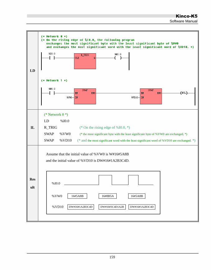
Kinco-K5
Software Manual
159
LD
IL
(* Network 0 *)
LD %I0.0
R_TRIG (* On the rising edge of %I0.0, *)
SWAP %VW0 (* the most significant byte with the least significant byte of %VW0 are exchanged, *)
SWAP %VD10 (* and the most significant word with the least significant word of %VD10 are exchanged. *)
Res
ult
Assume that the initial value of %VW0 is W#16#5A8B
and the initial value of %VD10 is DW#16#1A2B3C4D.
%I0.0
%VW0 16#5A8B 16#8B5A 16#5A8B
DW#16#1A2B3C4D DW#16#3C4D1A2B DW#16#1A2B3C4D%VD10

Kinco-K5
Software Manual
160
6.4 Compare Instructions
For all the compare instructions, BYTE comparisons are unsigned. INT, DINT and REAL comparisons are
signed.
6.4.1 GT (Greater Than)
Description
Name Usage Group
K5
K2 LD GT
IL GT GT IN1, IN2 P
Operands Input/Output Data Type Acceptable Memory Areas
IN1 Input BYTE, INT, DINT, REAL I, Q, M, V, L, SM, AI, AQ, T, C,
HC, constant, pointer
IN2 Input BYTE, INT, DINT, REAL I, Q, M, V, L, SM, AI, AQ, T, C,
HC, constant, pointer
OUT (LD) Output BOOL Power flow
Note: if the input parameter is real, check the accuracy of real data in 3.2 Data Format/3.4 constant.
The IN1 and IN2 must be of the same data type.
LD
If EN is 1, this instruction compares IN1 greater than IN2 and the Boolean result is assigned to OUT;
If EN is 0, this instruction is not executed, and OUT is set equal to 0.
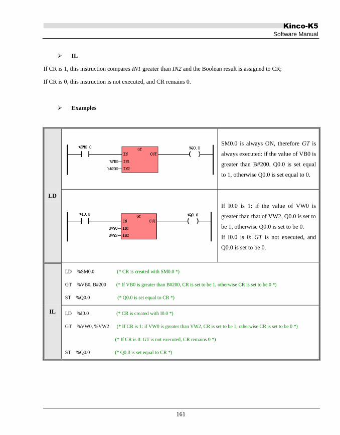
Kinco-K5
Software Manual
161
IL
If CR is 1, this instruction compares IN1 greater than IN2 and the Boolean result is assigned to CR;
If CR is 0, this instruction is not executed, and CR remains 0.
Examples
LD
SM0.0 is always ON, therefore GT is
always executed: if the value of VB0 is
greater than B#200, Q0.0 is set equal
to 1, otherwise Q0.0 is set equal to 0.
If I0.0 is 1: if the value of VW0 is
greater than that of VW2, Q0.0 is set to
be 1, otherwise Q0.0 is set to be 0.
If I0.0 is 0: GT is not executed, and
Q0.0 is set to be 0.
IL
LD %SM0.0 (* CR is created with SM0.0 *)
GT %VB0, B#200 (* If VB0 is greater than B#200, CR is set to be 1, otherwise CR is set to be 0 *)
ST %Q0.0 (* Q0.0 is set equal to CR *)
LD %I0.0 (* CR is created with I0.0 *)
GT %VW0, %VW2 (* If CR is 1: if VW0 is greater than VW2, CR is set to be 1, otherwise CR is set to be 0 *)
(* If CR is 0: GT is not executed, CR remains 0 *)
ST %Q0.0 (* Q0.0 is set equal to CR *)

Kinco-K5
Software Manual
162
6.4.2 GE (Greater than or Equal to)
Description
Name Usage Group
K5
K2 LD GE
IL GE GE IN1, IN2 P
Note: if the input parameter is real, check the accuracy of real data in 3.2 Data Format/3.4 constant.
The IN1 and IN2 must be of the same data type.
LD
If EN is 1, this instruction compares IN1 greater than or equal to IN2 and the Boolean result is assigned to OUT;
If EN is 0, this instruction is not executed, and OUT is set equal to 0.
IL
If CR is 1, this instruction compares IN1 greater than or equal to IN2 and the Boolean result is assigned to CR;
If CR is 0, this instruction is not executed, and CR remains 0.
Operands Input/Output Data Type Acceptable Memory Areas
IN1 Input BYTE, INT, DINT, REAL I, Q, M, V, L, SM, AI, AQ, T, C, HC,
constant, pointer
IN2 Input BYTE, INT, DINT, REAL I, Q, M, V, L, SM, AI, AQ, T, C, HC,
constant, pointer
OUT (LD) Output BOOL Power flow

Kinco-K5
Software Manual
163
Examples
LD
SM0.0 is always ON, therefore GE is
always executed: if VB0 is greater than
or equal to B#200, Q0.0 is set equal to
1, otherwise Q0.0 is set equal to 0.
If I0.0 is 1: if VW0 is greater than or
equal to VW2, Q0.0 is set to be 1,
otherwise Q0.0 is set to be 0.
If I0.0 is 0: GE is not executed, and
Q0.0 is set to be 0.
IL
LD %SM0.0 (* CR is created with SM0.0 *)
GE %VB0, B#200 (* If VB0 is greater than or equal to B#200, CR is set to be 1, otherwise CR is set to be 0 *)
ST %Q0.0 (* Q0.0 is set equal to CR *)
LD %I0.0 (* CR is created with I0.0 *)
GE %VW0, %VW2 (* If CR is 1: if VW0 is greater than or equal to VW2, CR is set to be 1, *)
(* otherwise CR is set to be 0; If CR is 0: GE is not executed, CR remains 0 *)
ST %Q0.0 (* Q0.0 is set equal to CR *)

Kinco-K5
Software Manual
164
6.4.3 EQ (Equal to)
Description
Name Usage Group
K5
K2 LD EQ
IL EQ EQ IN1, IN2 P
Note: if the input parameter is real, check the accuracy of real data in 3.2 Data Format/3.4 constant.
The IN1 and IN2 must be of the same data type.
LD
If EN is 1, this instruction compares IN1 equal to IN2 and the Boolean result is assigned to OUT;
If EN is 0, this instruction is not executed, and OUT is set equal to 0.
IL
If CR is 1, this instruction compares IN1 equal to IN2 and the Boolean result is assigned to CR;
If CR is 0, this instruction is not executed, and CR remains 0.
Operands Input/Output Data Type Acceptable Memory Areas
IN1 Input BYTE, INT, DINT, REAL I, Q, M, V, L, SM, AI, AQ, T, C, HC,
constant, pointer
IN2 Input BYTE, INT, DINT, REAL I, Q, M, V, L, SM, AI, AQ, T, C, HC,
constant, pointer
OUT (LD) Output BOOL Power flow

Kinco-K5
Software Manual
165
Examples
LD
SM0.0 is always ON, therefore EQ is
always executed: if the value of VB0 is
equal to B#200, Q0.0 is set equal to 1,
otherwise Q0.0 is set equal to 0.
If I0.0 is 1: if the value of VW0 is
equal to that of VW2, Q0.0 is set to be
1, otherwise Q0.0 is set to be 0.
If I0.0 is 0: EQ is not executed, and
Q0.0 is set to be 0.
IL
LD %SM0.0 (* CR is created with SM0.0 *)
EQ %VB0, B#200 (* If VB0 is equal to B#200, CR is set to be 1, otherwise CR is set to be 0 *)
ST %Q0.0 (* Q0.0 is set equal to CR *)
LD %I0.0 (* CR is created with I0.0 *)
EQ %VW0, %VW2 (* If CR is 1: if VW0 is equal to VW2, CR is set to be 1, otherwise CR is set to be 0 *)
(* If CR is 0: EQ is not executed, CR remains 0 *)
ST %Q0.0 (* Q0.0 is set equal to CR *)

Kinco-K5
Software Manual
166
6.4.4 NE (Not Equal to)
Description
Name Usage Group
K5
K2 LD NE
IL NE NE IN1, IN2 P
Note: if the input parameter is real, check the accuracy of real data in 3.2 Data Format/3.4 constant.
The IN1 and IN2 must be of the same data type.
LD
If EN is 1, this instruction compares IN1 not equal to IN2 and the Boolean result is assigned to OUT;
If EN is 0, this instruction is not executed, and OUT is set equal to 0.
IL
If CR is 1, this instruction compares IN1 not equal to IN2 and the Boolean result is assigned to CR;
If CR is 0, this instruction is not executed, and CR remains 0.
Operands Input/Output Data Type Acceptable Memory Areas
IN1 Input BYTE, INT, DINT, REAL I, Q, M, V, L, SM, AI, AQ, T, C, HC,
constant, pointer
IN2 Input BYTE, INT, DINT, REAL I, Q, M, V, L, SM, AI, AQ, T, C, HC,
constant, pointer
OUT (LD) Output BOOL Power flow

Kinco-K5
Software Manual
167
Examples
LD
SM0.0 is always ON, therefore NE is
always executed: if the value of VB0 is
not equal to B#200, Q0.0 is set equal
to 1, otherwise Q0.0 is set equal to 0.
If I0.0 is 1: if the value of VW0 is not
equal to that of VW2, Q0.0 is set to be
1, otherwise Q0.0 is set to be 0.
If I0.0 is 0: NE is not executed, and
Q0.0 is set to be 0.
IL
LD %SM0.0 (* CR is created with SM0.0 *)
NE %VB0, B#200 (* If VB0 is not equal to B#200, CR is set to be 1, otherwise CR is set to be 0 *)
ST %Q0.0 (* Q0.0 is set equal to CR *)
LD %I0.0 (* CR is created with I0.0 *)
NE %VW0, %VW2 (* If CR is 1: if VW0 is not equal to VW2, CR is set to be 1, otherwise CR is set to be 0 *)
(* If CR is 0: NE is not executed, CR remains 0 *)
ST %Q0.0 (* Q0.0 is set equal to CR *)

Kinco-K5
Software Manual
168
6.4.5 LT (Less than)
Description
Name Usage Group
K5
K2 LD LT
IL LT LT IN1, IN2 P
Note: if the input parameter is real, check the accuracy of real data in 3.2 Data Format/3.4 constant.
The IN1 and IN2 must be of the same data type.
LD
If EN is 1, this instruction compares IN1 less than IN2 and the Boolean result is assigned to OUT;
If EN is 0, this instruction is not executed, and OUT is set equal to 0.
IL
If CR is 1, this instruction compares IN1 less than IN2 and the Boolean result is assigned to CR;
If CR is 0, this instruction is not executed, and CR remains 0.
Operands Input/Output Data Type Acceptable Memory Areas
IN1 Input BYTE, INT, DINT, REAL I, Q, M, V, L, SM, AI, AQ, T, C, HC,
constant, pointer
IN2 Input BYTE, INT, DINT, REAL I, Q, M, V, L, SM, AI, AQ, T, C, HC,
constant, pointer
OUT (LD) Output BOOL Power flow

Kinco-K5
Software Manual
169
Examples
LD
SM0.0 is always ON, therefore LT is
always executed: if the value of VB0 is
less than B#200, Q0.0 is set equal to 1,
otherwise Q0.0 is set equal to 0.
If I0.0 is 1: if the value of VW0 is less
than that of VW2, Q0.0 is set to be 1,
otherwise Q0.0 is set to be 0.
If I0.0 is 0: LT is not executed, and
Q0.0 is set to be 0.
IL
LD %SM0.0 (* CR is created with SM0.0 *)
LT %VB0, B#200 (* If VB0 is less than B#200, CR is set to be 1, otherwise CR is set to be 0 *)
ST %Q0.0 (* Q0.0 is set equal to CR *)
LD %I0.0 (* CR is created with I0.0 *)
LT %VW0, %VW2 (* If CR is 1: if VW0 is less than VW2, CR is set to be 1, otherwise CR is set to be 0 *)
(* If CR is 0: LT is not executed, CR remains 0 *)
ST %Q0.0 (* Q0.0 is set equal to CR *)

Kinco-K5
Software Manual
170
6.4.6 LE (Less than or Equal to)
Description
Name Usage Group
K5
K2 LD LE
IL LE LE IN1, IN2 P
Note: if the input parameter is real, check the accuracy of real data in 3.2 Data Format/3.4 constant.
The IN1 and IN2 must be of the same data type.
LD
If EN is 1, this instruction compares IN1 less than or equal to IN2 and the Boolean result is assigned to OUT;
If EN is 0, this instruction is not executed, and OUT is set equal to 0.
IL
If CR is 1, this instruction compares IN1 less than or equal to IN2 and the Boolean result is assigned to CR; If
CR is 0, this instruction is not executed, and CR remains 0.
Operands Input/Output Data Type Acceptable Memory Areas
IN1 Input BYTE, INT, DINT, REAL I, Q, M, V, L, SM, AI, AQ, T, C, HC,
constant, pointer
IN2 Input BYTE, INT, DINT, REAL I, Q, M, V, L, SM, AI, AQ, T, C, HC,
constant, pointer
OUT (LD) Output BOOL Power flow

Kinco-K5
Software Manual
171
Examples
LD
SM0.0 is always ON, therefore LE is
always executed: if VB0 is less than or
equal to B#200, Q0.0 is set equal to 1,
otherwise Q0.0 is set equal to 0.
If I0.0 is 1: if VW0 is less than or equal
to VW2, Q0.0 is set to be 1, otherwise
Q0.0 is set to be 0.
If I0.0 is 0: LE is not executed, and
Q0.0 is set to be 0.
IL
LD %SM0.0 (* CR is created with SM0.0 *)
LE %VB0, B#200 (* If VB0 is less than or equal to B#200, CR is set to be 1, otherwise CR is set to be 0 *)
ST %Q0.0 (* Q0.0 is set equal to CR *)
LD %I0.0 (* CR is created with I0.0 *)
LE %VW0, %VW2 (* If CR is 1: if VW0 is less than or equal to VW2, CR is set to be 1, *)
(* otherwise CR is set to be 0; If CR is 0: LE is not executed, CR remains 0 *)
ST %Q0.0 (* Q0.0 is set equal to CR *)

Kinco-K5
Software Manual
172
6.5 Logical Operations
6.5.1 NOT
Description
Name Usage Group
K5
K2 LD NOT
IL NOT NOT OUT U
LD
The IN and OUT must be of the same data type.
If EN is 1, this instruction inverts each bit of IN and assigns the result to OUT.
If EN is 0, this instruction is not executed.
IL
If CR is 1, this instruction inverts each bit of OUT and still stores the result in OUT. It does not influence CR;
If CR is 0, this instruction is not executed.
Operands Input/Output Data Type Acceptable Memory Areas
IN Input BYTE, WORD, DWORD I, Q, M, V, L, SM, constant,
pointer
OUT Output BYTE, WORD, DWORD Q, M, V, L, SM, pointer

Kinco-K5
Software Manual
173
Examples
LD
If I0.0 is 0: NOT is not executed.
If I0.0 is 1: NOT inverts each bit
of VW2 and assigns the result to
VW20.
IL
LD %I0.0 (* CR is created with I0.0 *)
NOT %VW20 (* If CR is 1: NOT inverts each bit of VW20 and still stores the result in VW20 *)
(* If CR is 0: NOT instruction is not executed *)
Resu
lt
For the LD example, if NOT instruction is executed, the result will be as the following:
W#16#5555
Address
Value
VW2
W#16#AAAA
Address
Value
VW20

Kinco-K5
Software Manual
174
6.5.2 AND
Description
Name Usage Group
K5
K2 LD AND
IL AND AND IN1, OUT U
LD
The IN1, IN2 and OUT must be of the same data type.
If EN is 1, this instruction ANDs the corresponding bits of IN1 and IN2 and assigns the result to OUT.
If EN is 0, this instruction is not executed.
IL
The IN and OUT must be of the same data type.
If CR is 1, this instruction ANDs the corresponding bits of IN and OUT and assigns the result to OUT, and it
does not influence CR.
If CR is 0, this instruction is not executed.
Parameter Input/Output Data Type Acceptable Memory Areas
IN1 Input BYTE, WORD, DWORD I, Q, M, V, L, SM, constant, pointer
IN2 Input BYTE, WORD, DWORD I, Q, M, V, L, SM, constant, pointer
OUT Output BYTE, WORD, DWORD Q, M, V, L, SM, pointer

Kinco-K5
Software Manual
175
Examples
LD
If I0.0 is 0: AND is not executed.
If I0.0 is 1: The AND instruction
ANDs the corresponding bits of
VW0 and VW2, and assigns the
result to VW4.
IL
LD %I0.0 (* CR is created with I0.0 *)
AND %VW0, %VW2 (* If CR is 1: The AND instruction ANDs the corresponding bits of VW0 and VW2, *)
(* and still stores the result in VW2 *)
(* If CR is 0: The AND instruction is not executed *)
Resu
lt
For the LD example, if AND instruction is executed, the result will be as the following:
W#16#129B
Address
Value
VW0
W#16#120B
Address
Value
VW4
W#16#960F
VW2

Kinco-K5
Software Manual
176
6.5.3 ANDN
Description
Name Usage Group
K5
K2
LD ANDN
IL ANDN ANDN IN1, OUT U
LD
The IN1, IN2 and OUT must be of the same data type.
If EN is 1, this instruction ANDs the corresponding bits of IN1 and IN2, then inverts each bit of the result, and
assigns the final result to OUT. If EN is 0, this instruction is not executed.
IL
The IN and OUT must be of the same data type.
If CR is 1, this instruction ANDs the corresponding bits of IN and OUT, then inverts each bit of the result, and
assigns the final result to OUT. It does not influence CR.
If CR is 0, this instruction is not executed.
Parameter Input/Output Data Type Acceptable Memory Areas
IN1 Input BYTE, WORD, DWORD I, Q, M, V, L, SM, constant, pointer
IN2 Input BYTE, WORD, DWORD I, Q, M, V, L, SM, constant, pointer
OUT Output BYTE, WORD, DWORD Q, M, V, L, SM, pointer

Kinco-K5
Software Manual
177
Examples
LD
If I0.0 is 0: ANDN is not executed.
If I0.0 is 1: The ANDN instruction
ANDs the corresponding bits of
VW0 and VW2, then inverts each
bit of the result, and assigns the final
result to VW4.
IL
LD %I0.0 (* CR is created with I0.0 *)
ANDN %VW0, %VW2 (* If CR is 1: The ANDN instruction ANDs the corresponding bits of VW0 and VW2, *)
(* then inverts each bit of the result, and still stores the final result in VW2 *)
(* If CR is 0: The ANDN instruction is not executed *)
Resu
lt
For the LD example, if ANDN instruction is executed, the result will be as the following:
W#16#129B
Address
Value
VW0
W#16#EDF4
Address
Value
VW4
W#16#960F
VW2

Kinco-K5
Software Manual
178
6.5.4 OR
Description
Name Usage Group
K5
K2 LD OR
IL OR OR IN1, OUT U
LD
The IN1, IN2 and OUT must be of the same data type.
If EN is 1, this instruction ORs the corresponding bits of IN1 and IN2 and assigns the result to OUT.
If EN is 0, this instruction is not executed.
IL
The IN and OUT must be of the same data type.
If CR is 1, this instruction ORs the corresponding bits of IN and OUT and assigns the result to OUT, and it does
not influence CR.
If CR is 0, this instruction is not executed.
Parameter Input/Output Data Type Acceptable Memory Areas
IN1 Input BYTE, WORD, DWORD I, Q, M, V, L, SM, constant, pointer
IN2 Input BYTE, WORD, DWORD I, Q, M, V, L, SM, constant, pointer
OUT Output BYTE, WORD, DWORD Q, M, V, L, SM, pointer

Kinco-K5
Software Manual
179
Examples
LD
If I0.0 is 0: OR is not executed.
If I0.0 is 1: The OR instruction ORs
the corresponding bits of VW0 and
VW2, and assigns the result to VW4.
IL
LD %I0.0 (* CR is created with I0.0 *)
OR %VW0, %VW2 (* If CR is 1: The OR instruction ORs the corresponding bits of VW0 and VW2, *)
(* and still stores the result in VW2 *)
(* If CR is 0: The OR instruction is not executed *)
Resu
lt
For the LD example, if OR instruction is executed, the result will be as the following:
W#16#5555
Address
Value
VW0
W#16#FFFF
Address
Value
VW4
W#16#AAAA
VW2

Kinco-K5
Software Manual
180
6.5.5 ORN
Description
Name Usage Group
K5
K2 LD ORN
IL ORN ORN IN1, OUT U
Parameter Input/Output Data Type Acceptable Memory Areas
IN1 Input BYTE, WORD, DWORD I, Q, M, V, L, SM, constant, pointer
IN2 Input BYTE, WORD, DWORD I, Q, M, V, L, SM, constant, pointer
OUT Output BYTE, WORD, DWORD Q, M, V, L, SM, pointer
LD
The IN1, IN2 and OUT must be of the same data type.
If EN is 1, this instruction ORs the corresponding bits of IN1 and IN2, then inverts each bit of the result, and
assigns the final result to OUT. If EN is 0, this instruction is not executed.
IL
The IN and OUT must be of the same data type.
If CR is 1, this instruction ORs the corresponding bits of IN and OUT, then inverts each bit of the result, and
assigns the final result to OUT. It does not influence CR.
If CR is 0, this instruction is not executed.

Kinco-K5
Software Manual
181
Examples
LD
If I0.0 is 0: ORN is not executed.
If I0.0 is 1: The ORN instruction ORs the
corresponding bits of VW0 and VW2,
then inverts each bit of the result, and
assigns the final result to VW4.
IL
LD %I0.0 (* CR is created with I0.0 *)
ORN %VW0, %VW2 (* If CR is 1: The ORN instruction ORs the corresponding bits of VW0 and VW2, *)
(* then inverts each bit of the result, and still stores the final result in VW2 *)
(* If CR is 0: The ORN instruction is not executed *)
Resu
lt
For the LD example, if ORN instruction is executed, the result will be as the following:
W#16#129B
Address
Value
VW0
W#16#6960
Address
Value
VW4
W#16#960F
VW2

Kinco-K5
Software Manual
182
6.5.6 XOR (Exclusive OR)
Description
Name Usage Group
K5
K2
LD XOR
IL XOR XOR IN1, OUT U
Parameter Input/Output Data Type Acceptable Memory Areas
IN1 Input BYTE, WORD, DWORD I, Q, M, V, L, SM, constant, pointer
IN2 Input BYTE, WORD, DWORD I, Q, M, V, L, SM, constant, pointer
OUT Output BYTE, WORD, DWORD Q, M, V, L, SM, pointer
LD
The IN1, IN2 and OUT must be of the same data type.
If EN is 1, this instruction XORs the corresponding bits of IN1 and IN2 and assigns the result to OUT.
If EN is 0, this instruction is not executed.
IL
The IN and OUT must be of the same data type.
If CR is 1, this instruction XORs the corresponding bits of IN and OUT and assigns the result to OUT, and it
does not influence CR.
If CR is 0, this instruction is not executed.

Kinco-K5
Software Manual
183
Examples
LD
If I0.0 is 0: XOR is not executed.
If I0.0 is 1: The XOR instruction XORs
the corresponding bits of VW0 and
VW2, and assigns the result to VW4.
IL
LD %I0.0 (* CR is created with I0.0 *)
XOR %VW0, %VW2 (* If CR is 1: The XOR instruction XORs the corresponding bits of VW0 and VW2, *)
(* and still stores the result in VW2 *)
(* If CR is 0: The XOR instruction is not executed *)
Resu
lt
For the LD example, if XOR instruction is executed, the result will be as the following:
W#16#9514
Address
Value
VW0
W#16#2CB5
Address
Value
VW4
W#16#B9A1
VW2

Kinco-K5
Software Manual
184
6.6 Shift/Rotate Instructions
6.6.1 SHL (Shift left)
Description
Name Usage Group
K5
K2 LD SHL
IL SHL SHL OUT, N U
LD
The IN and OUT must be of the same data type.
If EN is 1, this instruction shifts the value of IN to the left by N bits, and each bit is filled with a zero while it is
shifted left. The result is assigned to OUT. If EN is 0, this instruction is not executed.
IL
If CR is 1, this instruction shifts the value of OUT to the left by N bits, and each bit is filled with a zero while it
is shifted left. The result is still stored in OUT. It does not influence CR.
If CR is 0, this instruction is not executed.
Operands Input/Output Data Type Acceptable Memory Areas
IN Input BYTE, WORD, DWORD I, Q, M, V, L, SM, constant, pointer
N Input BYTE I, Q, M, V, L, SM, constant, pointer
OUT Output BYTE, WORD, DWORD Q, M, V, L, SM, pointer

Kinco-K5
Software Manual
185
Examples
LD
If M0.0 is 0: SHL isn‟t executed.
If M0.0 is 1: SHL shifts QB0 to the left
by 1 bit, and the result is still assigned
to QB0.
IL
LD %M0.0 (* CR is created with M0.0 *)
SHL %QB0, B#1 (* If CR is 1: SHL shifts QB0 to the left by 1 bit, and the result is still stored in QB0 *)
(* If CR is 0: SHL instruction is not executed *)
Resu
lt
For the LD example, if SHL instruction is executed, the result will be as the following:
B#2#10000001QB0
After 1st shift
B#2#00000010 B#2#00000100QB0
After 2nd shift
B#2#00001000
After 3rd shift
B#2#00010000
After 4th shift

Kinco-K5
Software Manual
186
6.6.2 ROL (Rotate left)
Description
Name Usage Group
K5
K2 LD ROL
IL ROL ROL OUT, N U
Operands Input/Output Data Type Acceptable Memory Areas
IN Input BYTE, WORD, DWORD I, Q, M, V, L, SM, constant, pointer
N Input BYTE I, Q, M, V, L, SM, constant, pointer
OUT Output BYTE, WORD, DWORD Q, M, V, L, SM, pointer
LD
The IN and OUT must be of the same data type.
If EN is 1, this instruction rotates the value of IN to the left by N bits, and the MSB is rotated to the LSB. The
result is assigned to OUT. If EN is 0, this instruction is not executed.
IL
If CR is 1, this instruction rotates the value of OUT to the left by N bits, and the MSB is rotated to the LSB. The
result is still stored in OUT. It does not influence CR.
If CR is 0, this instruction is not executed.
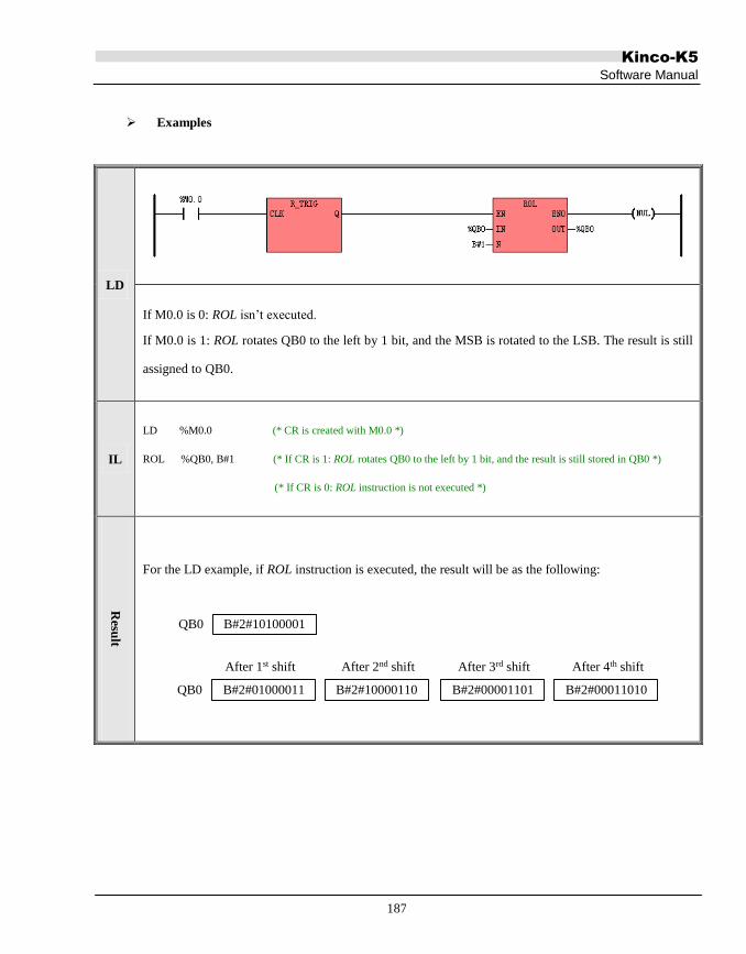
Kinco-K5
Software Manual
187
Examples
LD
If M0.0 is 0: ROL isn‟t executed.
If M0.0 is 1: ROL rotates QB0 to the left by 1 bit, and the MSB is rotated to the LSB. The result is still
assigned to QB0.
IL
LD %M0.0 (* CR is created with M0.0 *)
ROL %QB0, B#1 (* If CR is 1: ROL rotates QB0 to the left by 1 bit, and the result is still stored in QB0 *)
(* If CR is 0: ROL instruction is not executed *)
Resu
lt
For the LD example, if ROL instruction is executed, the result will be as the following:
B#2#10100001QB0
B#2#01000011 B#2#10000110QB0 B#2#00001101 B#2#00011010
After 1st shift After 2nd shift After 3rd shift After 4th shift

Kinco-K5
Software Manual
188
6.6.3 SHR (Shift right)
Description
Name Usage Group
K5
K2 LD SHR
IL SHR SHR OUT, N U
LD
The IN and OUT must be of the same data type.
If EN is 1, this instruction shifts the value of IN to the right by N bits, and each bit is filled with a zero while it is
shifted right. The result is assigned to OUT. If EN is 0, this instruction is not executed.
IL
If CR is 1, this instruction shifts the value of OUT to the right by N bits, and each bit is filled with a zero while
it is shifted right. The result is still stored in OUT. It does not influence CR.
If CR is 0, this instruction is not executed.
Operands Input/Output Data Type Acceptable Memory Areas
IN Input BYTE, WORD, DWORD I, Q, M, V, L, SM, constant, pointer
N Input BYTE I, Q, M, V, L, SM, constant, pointer
OUT Output BYTE, WORD, DWORD Q, M, V, L, SM, pointer

Kinco-K5
Software Manual
189
Examples
LD
If M0.0 is 0: SHR isn‟t executed.
If M0.0 is 1: SHR shifts QB0 to the
right by 1 bit, and the result is still
assigned to QB0.
IL
LD %M0.0 (* CR is created with M0.0 *)
SHR %QB0, B#1 (* If CR is 1: SHR shifts QB0 to the right by 1 bit, and the result is still stored in QB0 *)
(* If CR is 0: SHR instruction is not executed *)
Resu
lt
For the LD example, if SHR instruction is executed, the result will be as the following:
B#2#10000001QB0
B#2#01000000 B#2#00100000QB0 B#2#00010000 B#2#00001000
After 1st shift After 2nd shift After 3rd shift After 4th shift

Kinco-K5
Software Manual
190
6.6.4 ROR (Rotate right)
Description
Name Usage Group
K5
K2 LD ROR
IL ROR ROR OUT, N U
LD
The IN and OUT must be of the same data type.
If EN is 1, this instruction rotates the value of IN to the right by N bits, and the LSB is rotated to the MSB. The
result is assigned to OUT. If EN is 0, this instruction is not executed.
IL
If CR is 1, this instruction rotates the value of OUT to the right by N bits, and the LSB is rotated to the MSB.
The result is still stored in OUT. It does not influence CR.
If CR is 0, this instruction is not executed.
Operands Input/Output Data Type Acceptable Memory Areas
IN Input BYTE, WORD, DWORD I, Q, M, V, L, SM, constant, pointer
N Input BYTE I, Q, M, V, L, SM, constant, pointer
OUT Output BYTE, WORD, DWORD Q, M, V, L, SM, pointer

Kinco-K5
Software Manual
191
Examples
LD
If M0.0 is 0: ROR isn‟t executed.
If M0.0 is 1: ROR rotates QB0 to the right by 1 bit, and the LSB is rotated to the MSB. The result is still
assigned to QB0.
IL
LD %M0.0 (* CR is created with M0.0 *)
ROL %QB0, B#1 (* If CR is 1: ROR rotates QB0 to the right by 1 bit, and the result is still stored in QB0 *)
(* If CR is 0: ROR instruction is not executed *)
Resu
lt
For the LD example, if ROR instruction is executed, the result will be as the following:
B#2#10100001QB0
B#2#11010000 B#2#01101000QB0 B#2#00110100 B#2#00011010
After 1st shift After 2nd shift After 3rd shift After 4th shift

Kinco-K5
Software Manual
192
6.6.5 SHL_BLK (Bit String Shift Left)
Description
Name Usage Group
K5
K2
LD SHL_BLK
IL SHL_BLK SHL_BLK S_DATA, S_N, D_DATA, D_N U
Operands Input/Output Data Type Acceptable Memory Areas
S_DATA Input BOOL I, Q, M, V, L
S_N Input INT I, Q, V, M, L, SM, T, C, AI, AQ, Constant, Pointer
D_DATA Input/Output BOOL Q, M, V, L
D_N Input INT I, Q, V, M, L, SM, T, C, AI, AQ, Constant, Pointer
Note: the maximum of S_N, D_N is 1024, if the input value is larger than 1024, the
software considers it as 1024. If the S_N is larger than D_N , the software considers S_N
equals D_N. The S_N and D_N must be larger than 0.
Note: the S_DATA, D_DATA parameter is memory block whose length is changeable. The whole
block cannot be in the illegal area, or there will be unpredictable result.
This instruction shifts the number D_N of continuous bits, beginning with D_DATA, to the left by S_N bits.
Meanwhile, the number S_N of continuous bits, beginning with S_DATA, are filled into the right most bits of
D_DATA.
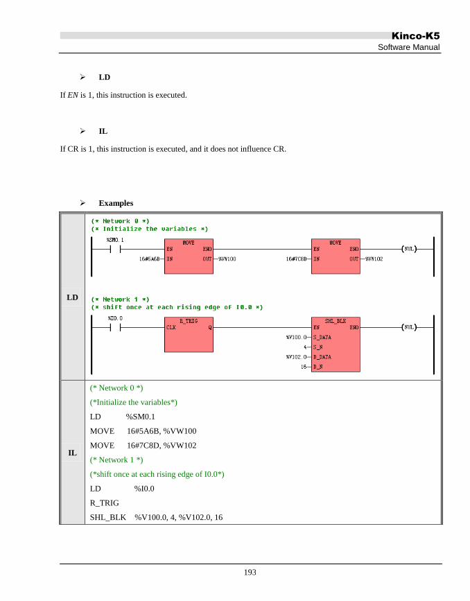
Kinco-K5
Software Manual
193
LD
If EN is 1, this instruction is executed.
IL
If CR is 1, this instruction is executed, and it does not influence CR.
Examples
LD
IL
(* Network 0 *)
(*Initialize the variables*)
LD %SM0.1
MOVE 16#5A6B, %VW100
MOVE 16#7C8D, %VW102
(* Network 1 *)
(*shift once at each rising edge of I0.0*)
LD %I0.0
R_TRIG
SHL_BLK %V100.0, 4, %V102.0, 16
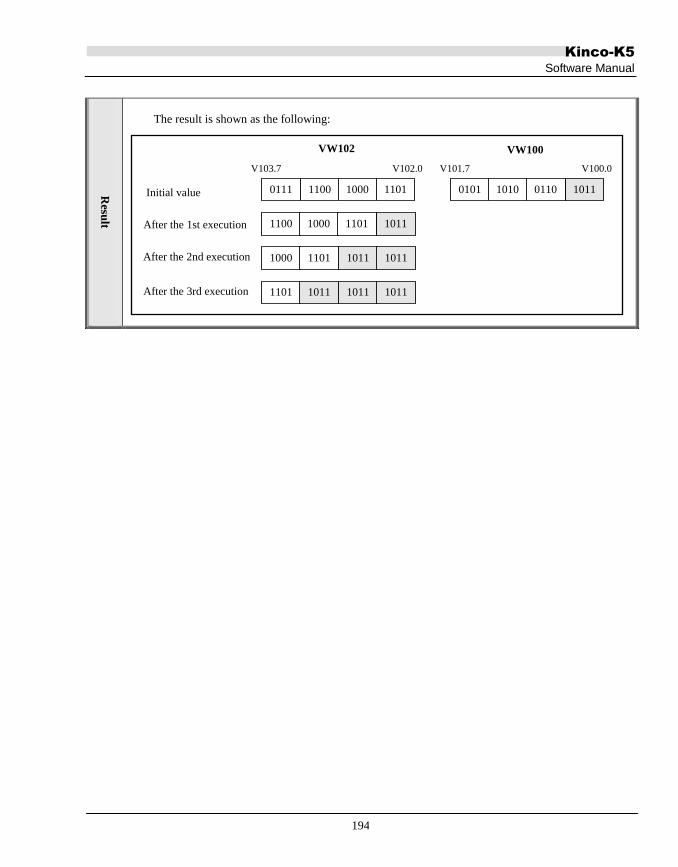
Kinco-K5
Software Manual
194
Resu
lt
The result is shown as the following:
Initial value
After the 1st execution
V102.0V103.7
0111 1100 1000 1101 10110101 1010 0110
V100.0V101.7
10111100 1000 1101
1011 10111000 1101
1011 10111101 1011
VW102 VW100
After the 2nd execution
After the 3rd execution

Kinco-K5
Software Manual
195
6.6.6 SHR_BLK (Bit String Shift Right)
Description
Name Usage Group
K5
K2 LD SHR_BLK
IL SHR_BLK SHR_BLK S_DATA, S_N, D_DATA, D_N U
Operands Input/Output Data Type Acceptable Memory Areas
S_DATA Input BOOL I, Q, M, V, L
S_N Input INT I, Q, V, M, L, SM, T, C, AI, AQ, Constant, Pointer
D_DATA Input/Output BOOL Q, M, V, L
D_N Input INT I, Q, V, M, L, SM, T, C, AI, AQ, Constant, Pointer
Note: the maximum of S_N, D_N is 1024, if the input value is larger than 1024, the
software considers it as 1024. If the S_N is larger than D_N , the software considers S_N
equals D_N. The S_N and D_N must be larger than 0.
Note: the S_DATA, D_DATA parameter is memory block whose length is changeable. The whole
block cannot be in the illegal area, or there will be unpredictable result.
This instruction shifts the number D_N of continuous bits, beginning with D_DATA, to the right by S_N bits.
Meanwhile, the number S_N of continuous bits, beginning with S_DATA, are filled into the left most bits of
D_DATA.

Kinco-K5
Software Manual
196
LD
If EN is 1, this instruction is executed.
IL
If CR is 1, this instruction is executed, and it does not influence CR.
Examples
LD
IL
(* Network 0 *)
(*Initialize the variables*)
LD %SM0.1
MOVE 16#5A6B, %VW100
MOVE 16#7C8D, %VW102
(* Network 1 *)
(*Shift once at each rising edge of I0.0*)
LD %I0.0
R_TRIG
SHR_BLK %V100.0, 4, %V102.0, 16

Kinco-K5
Software Manual
197
Resu
lt
The result is shown as the following:
V102.0V103.7
0111 1100 1000 1101 10110101 1010 0110
V100.0V101.7
10001011 0111 1100
0111 11001011 1011
1011 01111011 1011
VW102 VW100
Initial value
After the 1st execution
After the 2nd execution
After the 3rd execution

Kinco-K5
Software Manual
198
6.7 Convert Instructions
6.7.1 DI_TO_R (DINT To REAL)
Description
Name Usage Group
K5
K2 LD DI_TO_R
IL DI_TO_R DI_TO_R IN, OUT U
Operands Input/Output Data Type Acceptable Memory Areas
IN Input DINT I, Q, M, V, L, SM, HC, Constant
OUT Output REAL V, L
This instruction converts a DINT value (IN) to a REAL value and assigns the result to OUT.
LD
If EN is 1, this instruction is executed.
IL
If CR is 1, this instruction is not executed, and it does not influence CR.

Kinco-K5
Software Manual
199
Examples
LD
SM0.0 is always ON, therefore
DI_TO_R is always executed: The
value of MD0 is converted to a REAL
value that is assigned to VR100.
IL
LD %SM0.0 (* CR is created SM0.0 *)
DI_TO_R %MD0, %VR100 (* The value of MD0 is converted to a REAL value that is assigned to VR100 *)
Resu
lt
The result is shown as the following:
DI#123
MD0
123.0
VR100
DI#-9876 -9876.0

Kinco-K5
Software Manual
200
6.7.2 R_TO_DI (REAL To DINT)
Description
Name Usage Group
K5
K2 LD R_TO_DI
IL R_TO_DI R_TO_DI IN, OUT U
Operands Input/Output Data Type Acceptable Memory Areas
IN Input REAL V, L, constant
OUT Output DINT M, V, L, SM
This instruction converts a REAL value (IN) to a DINT value and assigns the result to OUT. During the
conversion, the decimal fraction is cut off.
LD
If EN is 1, this instruction is executed.
IL
If CR is 1, this instruction is executed, and it does not influence CR.

Kinco-K5
Software Manual
201
Examples
LD
SM0.0 is always ON, therefore
R_TO_DI is always executed: The
value of VD4000 is converted to a
DINT value that is assigned to VD0.
IL
LD %SM0.0 (* CR is created SM0.0 *)
R_TO_DI %VD4000, %VD0 (* The value of VD4000 is converted to a DINT value that is assigned to VD0 *)
Resu
lt
The result is shown as the following:
123.4
VD0
DI#123
VR100
5213.6 DI#5214

Kinco-K5
Software Manual
202
6.7.3 B_TO_I ( BYTE To INT )
Description
Name Usage Group
K5
K2 LD B_TO_I
IL B_TO_I B_TO_I IN, OUT U
Operands Input/Output Data Type Acceptable Memory Areas
IN Input BYTE I, Q, M, V, L, SM, Constant
OUT Output INT Q, M, V, L, SM, AQ
This instruction converts the input byte IN to an integer value and assigns the result to OUT.
LD
If EN is 1, this instruction is executed.
IL
If CR is 1, this instruction is executed, and it does not influence CR.

Kinco-K5
Software Manual
203
6.7.4 I_TO_B ( INT To BYTE )
Description
Name Usage Group
K5
K2 LD I_TO_B
IL I_TO_B I_TO_B IN, OUT U
Operands Input/Output Data Type Acceptable Memory Areas
IN Input INT I, Q, M, V, L, SM, AI, AQ, T, C, Constant
OUT Output BYTE Q, M, V, L, SM
Note: If the input parameter exceeds the range of output data format, there will be an error. The
output value will be calculated by force format transformation with C language rule.
This instruction assigns the least byte of the input IN to the OUT.
The range of byte is from B#0 to B#255, if the value of IN exceeds this range, the result will be lower byte
value of IN parameter; K5 CPU will also recode the overflow error.
LD
If EN is 1, this instruction is executed.
IL
If CR is 1, this instruction is executed, and it does not influence CR.

Kinco-K5
Software Manual
204
Examples
LD
SM0.0 is always 1, so I_TO_B is
always be executed: assigns VB0 (the
least byte of VW0) to VB10.
IL LD %SM0.0
I_TO_B %VW0, %VB10
Resu
lt
The result is shown as the following:
24
VW0
B#24
VB10
255 B#255
I#16#FFFD B#16#FD

Kinco-K5
Software Manual
205
6.7.5 DI_TO_I ( DINT To INT )
Description
Name Usage Group
K5
K2 LD DI_TO_I
IL DI_TO_I DI_TO_I IN, OUT U
Operands Input/Output Data Type Acceptable Memory Areas
IN Input DINT I, Q, M, V, L, SM, HC, Constant
OUT Output INT Q, M, V, L, SM, AQ
Note: If the input parameter exceeds the range of output data format, there will be an error. The
output value will be calculated by force format transformation with C language rule
This instruction assigns the least word of the input IN to the OUT.
The range of integer value is from -32768 to 32767, if the value of IN exceeds this range, the result will be
lower word value of IN parameter; K5 CPU will also recode the overflow error.
LD
If EN is 1, this instruction is executed.
IL
If CR is 1, this instruction is executed, and it does not influence CR.

Kinco-K5
Software Manual
206
Examples
LD
SM0.0 is always 1, so DI_TO_I is
always executed: assigns VW0 (the
least word of VD0) to VW10.
IL LD %SM0.0
DI_TO_I %VD0, %VW10
Resu
lt
The result is shown as the following:
DI#12345
VD0
12345
VW10
DI#-234 -234
DI#16#7A8B9C1D I#16#9C1D

Kinco-K5
Software Manual
207
6.7.6 I_TO_DI ( INT To DINT )
Description
Name Usage Group
K5
K2 LD I_TO_DI
IL I_TO_DI I_TO_DI IN, OUT U
Operands Input/Output Data Type Acceptable Memory Areas
IN Input INT I, Q, M, V, L, SM, AI, AQ, T, C, Constant
OUT Output DINT Q, M, V, L, SM
This instruction converts the input integer IN to a DINT value and assigns the result to OUT.
LD
If EN is 1, this instruction is executed.
IL
If CR is 1, this instruction is executed, and it does not influence CR.

Kinco-K5
Software Manual
208
6.7.7 BCD_TO_I ( BCD To INT )
Description
Name Usage Group
K5
K2 LD BCD_TO_I
IL BCD _TO_I BCD _TO_I IN, OUT U
Operands Input/Output Data Type Acceptable Memory Areas
IN Input WORD I, Q, M, V, L, SM, Constant
OUT Output INT Q, M, V, L, SM, AQ
This instruction converts the input Binary-Coded Decimal value (IN) to an integer value and assigns the result
to the OUT.
Note: The 8421 codes are adopted for the BCD code. The valid range of IN is 0 to 9999 BCD.
LD
If EN is 1, this instruction is executed.
IL
If CR is 1, this instruction is executed, and it does not influence CR.

Kinco-K5
Software Manual
209
Examples
LD
SM0.0 is always 1, so BCD_TO_I is
always be executed: converts VW0
from BCD to an integer and assigns it
to VW10.
IL LD %SM0.0
BCD_TO_I %VW0, %VW10
Resu
lt
The result is shown as the following:
VW0 VW10
99
4567
9999
16#99
16#4567
16#9999

Kinco-K5
Software Manual
210
6.7.8 I_TO_BCD (INT To BCD )
Description
Name Usage Group
K5
K2 LD I_TO_BCD
IL I_TO_BCD I _TO_BCD IN, OUT U
Operands Input/Output Data Type Acceptable Memory Areas
IN Input INT I, Q, M, V, L, SM, AI, AQ, T, C, Constant
OUT Output WORD Q, M, V, L, SM
Note: If the Input parameter of I_TO_BCD exceeds the range, there will be an error. If the input is
smaller than minimum value, plc considers it as minimum value, if the input is larger than maximum
value; plc considers it as maximum value.
Note: BCD use 8421 code, the available range of input is from 0 to 9999.If the IN is smaller than 0,
the result is 0, if IN is larger than 9999, the transform result is 9999 BCD. K5 CPU will also recode the
overflow error
This instruction converts the input integer value (IN) to a Binary-Coded Decimal value and assigns the result to
the OUT.
Note: The 8421 codes are adopted for the BCD code. The valid range of IN is 0 to 9999.
LD
If EN is 1, this instruction is executed.

Kinco-K5
Software Manual
211
IL
If CR is 1, this instruction is executed, and it does not influence CR.
Examples
LD
SM0.0 is always 1, so I_TO_ BCD is
always be executed: converts VW0 to
a BCD value and assigns it to VW10.
IL LD %SM0.0
I_TO_ BCD %VW0, %VW10
Resu
lt
The result is shown as the following:
VW0 VW10
99
4567
9999
16 # 99
16 # 4567
16 # 9999

Kinco-K5
Software Manual
212
6.7.9 I_TO_A ( INT To ASCII )
Description
Name Usage Group
K5
K2
LD I_TO_A
IL I_TO_A I_TO_A IN, OUT, FMT U
Operands Input/Output Data Type Acceptable Memory Areas
IN Input INT I, Q, M, V, L, SM, AI, AQ, T, C, Constant
FMT Input BYTE I, Q, M, V, L, SM
OUT Output BYTE Q, M, V, L, SM
Note: the OUT parameter is memory block whose length is changeable. The whole block cannot be
in the illegal area, or there will be unpredictable result.
This instruction converts an integer value (IN) to an ASCII string, then formats the string according to FMT and
put the result into the Output Buffer beginning with OUT. The conversion result of a positive value does not
include any sign, and the conversion result of a negative value begins with a leading minus sign (-).
The OUT defines the starting address of the Output Buffer, which occupies a memory range of 8 successive
bytes. In the buffer, the strings are right alignment, and the free bytes are filled with spaces (whose ASCII is 32).
The FMT is used to format the string, and the rules are shown in the figure below:

Kinco-K5
Software Manual
213
(1) nnn --- This field specifies the number of digits of the decimal part.
Its available rang is 0 to 5. 0 stands for no decimal part.
(2) c --- This field specifies the separator between the whole number and the fraction:
0 for a decimal point (whose ASCII is 46), and 1 for a comma(whose ASCII is 44).
(3) The upper 4 bits must be zero.
MSB LSB
0
7
0
6
0
5
0
4
c
3
n
2
n
1
n
0
LD
If EN is 1, this instruction is executed.
IL
If CR is 1, this instruction is executed, and it does not influence CR.
Examples
LD
SM0.0 is always 1, so the instruction
I_TO_A is always executed: converts
the value of VW0 to a string, and
format the string and put the result to a
buffer beginning with VB10.
IL LD %SM0.0
I_TO_A %VW0, %VB10, %VB100

Kinco-K5
Software Manual
214
Resu
lt
The result is as the following:
B#3
VB100 VW0 Result
VB10
12
-23456
32 32 32 48
‘ ’‘ ’‘ ’‘0’
46 48 49 50
‘.’‘0’‘1’‘2’
32 45 50 51
‘ ’‘-’‘2’‘3’
46 52 53 54
‘.’‘4’‘5’‘6’
VB17

Kinco-K5
Software Manual
215
6.7.10 DI_TO_A ( DINT To ASCII )
Description
Name Usage Group
K5
K2 LD DI_TO_A
IL DI_TO_A DI_TO_A IN, OUT, FMT U
Operands Input/Output Data Type Acceptable Memory Areas
IN Input DINT I, Q, M, V, L, SM, HC, Constants
FMT Input BYTE I, Q, M, V, L, SM
OUT Output BYTE Q, M, V, L, SM
Note: the OUT parameter is memory block whose length is changeable. The whole block cannot be
in the illegal area, or there will be unpredictable result.
This instruction converts a DINT value (IN) to an ASCII string, then formats the string according to FMT and put
the result into the Output Buffer beginning with OUT. The conversion result of a positive value does not include
any sign, and the conversion result of a negative value begins with a leading minus sign (-).
The OUT defines the starting address of the Output Buffer, which occupies a memory range of 12 successive
bytes. In the buffer, the strings are right alignment, and the free bytes are filled with spaces (whose ASCII is 32).
The FMT is used to format the string, and the rules are shown in the figure below:

Kinco-K5
Software Manual
216
(1) nnn --- This field specifies the number of digits of the decimal part.
Its available rang is 0 to 5. 0 stands for no decimal part.
(2) c --- This field specifies the separator between the whole number and the fraction:
0 for a decimal point (whose ASCII is 46), and 1 for a comma(whose ASCII is 44).
(3) The upper 4 bits must be zero.
MSB LSB
0
7
0
6
0
5
0
4
c
3
n
2
n
1
n
0
LD
If EN is 1, this instruction is executed.
IL
If CR is 1, this instruction is executed, and it does not influence CR.
Examples
LD
SM0.0 is always 1, so the instruction
DI_TO_A is always executed: Convert
the value of VD0 to a string, and
format the string and put it to a buffer
beginning with VB10.
IL LD %SM0.0
DI_TO_A %VD0, %VB10, %VB100

Kinco-K5
Software Manual
217
Resu
lt
The result is as the following:
B # 3
VB 100 VD0 Result
DI#12
DI#123456
VB10 VB21
32 32 32 32 48
‘ ’ ‘ ’‘ ’‘0’
46 48 49 50
‘.’‘0’‘1’‘2’
32 32 32
‘ ’ ‘ ’‘ ’‘ ’
32 45 49 50 51
‘-’‘1’‘2’‘3’
46 52 53 54
‘.’‘4’‘5’‘6’
32 32 32
‘ ’ ‘ ’‘ ’‘ ’

Kinco-K5
Software Manual
218
6.7.11 R_TO_A ( REAL To ASCII )
Description
Name Usage Group
K5
K2
LD R_TO_A
IL R_TO_A R_TO_A IN, OUT, FMT U
Operands Input/Output Data Type Acceptable Memory Areas
IN Input REAL V, L, Constants
FMT Input BYTE I, Q, M, V, L, SM
OUT Output BYTE Q, M, V, L, SM
Note: the OUT parameter is memory block whose length is changeable. The whole block cannot be
in the illegal area, or there will be unpredictable result.
Note: this instruction takes a little long to run, if there are many R_TO_A in operation at the same
time, it may trigger the watch dog, user can use WDR instruction to delay the watch dog time.
Note: If the input or output of this instruction exceeds the range, there will be an error. The whole
output area will be filled by blank space. The range of input is from -2147480000 to 4294960000.
This instruction converts a REAL value (IN) to an ASCII string, then formats the string according to FMT and
put the result into the Output Buffer beginning with OUT. The conversion result of a positive value does not
include any sign, and the conversion result of a negative value begins with a leading minus sign (-). If the digits
of the decimal part of IN is larger than the nnn in FMT, which specifies the digits of the decimal part in the
string, then IN is round off before being converted. Otherwise, if it is less than nnn, the missing digits of the
decimal part are filled with 0 in the string.

Kinco-K5
Software Manual
219
The OUT defines the starting address of the Output Buffer, whose size is specified in FMT. In the buffer, the
strings are right alignment, and the free bytes are filled with spaces (whose ASCII is 32).
The FMT is used to format the string, and the rules are shown in the figure below:
(1) nnn --- This field specifies the number of digits of the decimal part.
Its available rang is 0 to 5. 0 stands for no decimal part.
(2) c --- This field specifies the separator between the whole number and the fraction:
0 for a decimal point (whose ASCII is 46), and 1 for a comma(whose ASCII is 44).
(3) ssss --- This field specifies the size of the buffer.
Its available rang is 3 to 15, and it must be greater than nnn.
MSB LSB
s
7
s
6
s
5
s
4
c
3
n
2
n
1
n
0
Note: If the length of the resulting string exceeds the length of the Output Buffer, then the whole buffer will be
filled with spaces (whose ASCII is 32).
LD
If EN is 1, this instruction is executed.
IL
If CR is 1, this instruction is executed, and it does not influence CR.

Kinco-K5
Software Manual
220
Examples
LD
SM0.0 is always 1, so the instruction
DI_TO_A is always executed: Convert
the value of VR0 to a string, and
format the string and put it to a buffer
beginning with VB10.
IL LD %SM0.0
R_TO_A %VR0, %VB10, %VB100
Res
ult
The result is as the following:
B#16#83
VB100 VR0 Result
VB10 VB17
123.4
-123.4567
32 49 50 51
‘ ’‘1’‘2’‘3’
46 52 48 48
‘.’‘4’‘0’‘0’
45 49 50 51
‘-’‘1’‘2’‘3’
46 52 53 55
‘.’‘4’‘5’‘7’

Kinco-K5
Software Manual
221
6.7.12 H_TO_A ( Hexadecimal To ASCII )
Description
Name Usage Group
K5
K2
LD H_TO_A
IL H_TO_A H_TO_A IN, OUT, LEN U
Operands Input/Output Data Type Acceptable Memory Areas
IN Input BYTE I, Q, M, V, L, SM
LEN Input BYTE I, Q, M, V, L, SM, Constants
OUT Output BYTE Q, M, V, L, SM
Note: the IN,OUT parameter is memory block whose length is changeable. The whole block cannot
be in the illegal area, or there will be unpredictable result.
This instruction converts the number LEN of hexadecimal digits, beginning with IN, to an ASCII string, and put
the string into the Output Buffer beginning with OUT.
Note: Every 4 binary digits makes 1 hexadecimal digit, so every input byte includes 2 hexadecimal digits, and
so the size of the Output Buffer occupies is LEN*2 bytes.
LD
If EN is 1, this instruction is executed.
IL
If CR is 1, this instruction is executed, and it does not influence CR.

Kinco-K5
Software Manual
222
Examples
LD
SM0.0 is always 1, so H_TO_A is
always executed: converts 2-bytes
hexadecimal digits, beginning with
VB0, to a string and put the result into
the buffer which occupies 4 continuous
bytes beginning with VB10.
IL LD %SM0.0
H_TO_A %VB0, %VB10, B#2
Res
ult
The result is as the following:
B#16#1A
VB0 VB1 Result
VB10 VB13
B#16#2B 49 65 50 66
B#16#8DB#16#7C
‘1’‘A’‘2’‘B’
55 67 56 68
‘7’‘C’‘8’‘D’

Kinco-K5
Software Manual
223
6.7.13 A_TO_H ( ASCII to Hexadecimal )
Description
Name Usage Group
K5
K2
LD A_TO_H
IL A_TO_H A_TO_H IN, OUT, LEN U
Operands Input/Output Data Type Acceptable Memory Areas
IN Input BYTE I, Q, M, V, L, SM
LEN Input BYTE I, Q, M, V, L, SM, Constants
OUT Output BYTE Q, M, V, L, SM
Note: the IN,OUT parameter is memory block whose length is changeable. The whole block cannot
be in the illegal area, or there will be unpredictable result.
This instruction converts the number LEN of ASCII characters, beginning with IN, to hexadecimal digits, and
put the digits into the Output Buffer beginning with OUT. Note:Every 4 binary digits makes 1 hexadecimal digit,
so every input byte, which stands for an ASCII character, occupies 4 binary digits of memory space (i.e., a half
byte) in the Output Buffer.
The valid ASCII input range is: B#16#30 to B#16#39 (stands for the characters 0 to 9), B#16#41 to B#16#46
(stands for the characters A to F), B#16#61 to B#16#66 (stands for the characters a to f).
LD
If EN is 1, this instruction is executed.

Kinco-K5
Software Manual
224
IL
If CR is 1, this instruction is executed, and it does not influence CR.
Examples
LD
SM0.0 is always 1, so A_TO_H is
always executed: converts the 3-bytes
ASCII string, beginning with VB0, to
hexadecimal digits, and put the result
into the Output Buffer beginning with
VB100.
IL LD %SM0.0
A_TO_H %VB0, %VB10, B#3
Res
ult
The result is as the following:
Note: x stands for this half byte (4 bits) keeps the original value.
VB0 VB1 VB2 VB10 VB11
51 56 54 B#16#38 B#16#6x
55 65 49 B#16#7A B#16#1x
‘3’ ‘8’ ‘6’
‘7’ ‘A’ ‘1’

Kinco-K5
Software Manual
225
6.7.14 ENCO (Encoding)
Description
Name Usage Group
K5
K2
LD ENCO
IL ENCO ENCO IN, OUT U
Operands Input/Output Data Type Acceptable Memory Areas
IN Input WORD I, Q, M, V, L, SM, Constant
OUT Output BYTE Q, M, V, L, SM
This instruction checks the input Word IN from the least significant bit, and writes the bit number of the first bit
equal to 1 into the output byte OUT. Note: If the value of IN is 0, the result is meaningless.
LD
If EN is 1, this instruction is executed.
IL
If CR is 1, this instruction is executed, and it does not influence CR.

Kinco-K5
Software Manual
226
Examples
LD
SM0.0 is always 1, so ENCO is always
executed: writes the bit number of the
first bit equal to 1 into VB10.
IL LD %SM0.0
ENCO %VW0, %VB10
Res
ult
The result is as the following:
B#9
VB10VW0
0(LSB)(MSB)15 9
0 0 0 0 0 0 1 0 0 0 0 0 0 0 0 0
0 0 0 1 0 0 0 0 0 0 0 1 0 0 0 0
412
B#4

Kinco-K5
Software Manual
227
6.7.15 DECO (Decoding)
Description
Name Usage Group
K5
K2
LD DECO
IL DECO DECO IN, OUT U
Operands Input/Output Data Type Acceptable Memory Areas
IN Input BYTE I, Q, M, V, L, SM, Constant
OUT Output WORD Q, M, V, L, SM
This instruction sets the bit in the output word OUT that corresponds to the bit number represented by the least
significant “nibble” (4 bits) of the input byte IN. All other bits in the OUT are reset.
LD
If EN is 1, this instruction is executed.
IL
If CR is 1, this instruction is executed, and it does not influence CR.

Kinco-K5
Software Manual
228
Examples
LD
SM0.0 is always 1, so DECO is always
executed: sets the bit in VW10 which
corresponds to the bit number
represented by the least significant
“nibble” of VB0.
IL LD %SM0.0
DECO %VB0, %VW10
Res
ult
The result is as the following:
0(LSB)
VW10
(MSB)15 9
0 0 0 0 0 0 1 0 0 0 0 0 0 0 0 0
0 0 0 0 0 0 0 0 0 0 0 1 0 0 0 0
4
B#9
VB0
B#16#D4

Kinco-K5
Software Manual
229
6.7.16 SEG ( 7-segment Display)
Description
Name Usage Group
K5
K2 LD SEG
IL SEG SEG IN, OUT U
Operands Input/Output Data Type Acceptable Memory Areas
IN Input BYTE I, Q, M, V, L, SM, Constant
OUT Output BYTE Q, M, V, L, SM
This instruction generates a bit pattern of a 7-segment display according to the value represented by the least
significant “nibble” (4 bits) of the input byte IN, and then put the result into the OUT.
a
b
c
d
e
f g
IN(LSD) Display
OUT
(- g f e d c b a)
0
1
2
3
4
5
6
7
0
0
0
0
0
0
0
0
0
0
1
1
1
1
1
0
1
0
0
0
1
1
1
0
1
0
1
0
0
0
1
0
1
0
1
1
0
1
1
0
1
1
0
1
1
1
1
1
1
1
1
1
1
0
0
1
1
0
1
1
0
1
1
1
0
1
2
3
4
5
6
7
IN(LSD) Display
OUT
(- g f e d c b a)
8
9
A
B
C
D
E
F
0
0
0
0
0
0
0
0
1
1
1
1
0
1
1
1
1
1
1
1
1
0
1
1
1
0
1
1
1
1
1
1
1
0
0
1
1
1
1
0
1
1
1
1
0
1
0
0
1
1
1
0
0
1
0
0
1
1
1
0
1
0
1
1
8
9
A
B
C
D
E
F
LD
If EN is 1, this instruction is executed.
IL
If CR is 1, this instruction is executed, and it does not influence CR.

Kinco-K5
Software Manual
230
6.7.17 TRUNC (Truncate)
Description
Name Usage Group
K5
K2 LD TRUNC
IL TRUNC TRUNC IN, OUT U
Operands Input/Output Data Type Acceptable Memory Areas
IN Input REAL V, L, Constant
OUT Output DINT M, V, L, SM
This instruction converts the REAL value IN to a DINT value and assigns the result to the OUT. The decimal
part of IN is truncated off.
LD
If EN is 1, this instruction is executed.
IL
If CR is 1, this instruction is executed, and it does not influence CR.
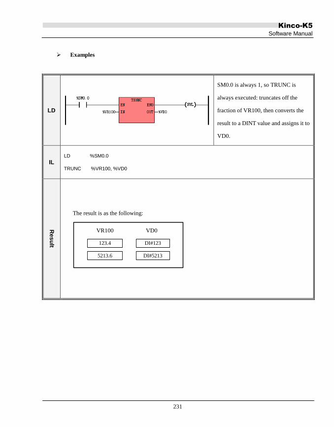
Kinco-K5
Software Manual
231
Examples
LD
SM0.0 is always 1, so TRUNC is
always executed: truncates off the
fraction of VR100, then converts the
result to a DINT value and assigns it to
VD0.
IL LD %SM0.0
TRUNC %VR100, %VD0
Res
ult
The result is as the following:
123.4
VD0
DI#123
VR100
5213.6 DI#5213

Kinco-K5
Software Manual
232
6.8 Numeric Instructions
6.8.1 ADD and SUB
Description
Name Usage Group
K5
K2
LD
ADD
SUB
IL
ADD ADD IN1, OUT
U
SUB SUB IN1, OUT
LD
The IN1, IN2 and OUT must be of the same data type.
If EN is 1, the role that the ADD instruction plays is: OUT=IN1+IN2, and the role that the SUB instruction
plays is: OUT=IN1-IN2.
IL
Operands Input/Output Data Type Acceptable Memory Areas
IN1 Input INT, DINT, REAL I, Q, AI, AQ, M, V, L, SM, T, C, HC, constant,
Pointer
IN2 Input INT, DINT, REAL I, Q, AI, AQ, M, V, L, SM, T, C, HC, constant,
Pointer
OUT Output INT, DINT, REAL Q, AQ, M, V, L, SM, Pointer

Kinco-K5
Software Manual
233
The IN1 and OUT must be of the same data type.
If CR is 1, the role that the ADD instruction plays is: OUT=OUT+IN1, and the role that the SUB instruction
plays is: OUT=OUT - IN1. The ADD and SUB instructions won‟t influence CR.
Examples
LD
If I0.0 is 0: ADD isn‟t executed.
If I0.0 is 1: The instruction adds VR0
and 345.67, and assigns the result to
VR4.
If I0.0 is 0: SUB isn‟t executed.
If I0.0 is 1: The instruction subtracts
45 from VW0, and assigns the result to
VW2.
IL
LD %I0.0
ADD 345.67, %VR4
(* CR is created with I0.0 *)
(* If CR is 1: VR4 = VR0 +345.67 *)
(* If CR is 0: the instruction isn‟t executed *)
LD %I0.0
SUB 45, %VW2
(* CR is created with I0.0 *)
(* If CR is 1: VW2 = VW0 - 45 *)
(* If CR is 0: the instruction isn‟t executed *)

Kinco-K5
Software Manual
234
6.8.2 MUL and DIV
Description
Name Usage Group
K5
K2
LD
MUL
DIV
IL
MUL MUL IN1, OUT
U
DIV DIV IN1, OUT
Note: If the DIV is 0 , there will be an error, the output keeps the last calculated value. Check the
definition of real data 0 in 3.2 Data Format 3.4 Constant.
LD
The IN1, IN2 and OUT must be of the same data type.
If EN is 1, the role that the MUL instruction plays is: OUT=IN1×IN2, and the role that the DIV instruction plays
is: OUT=IN1÷IN2.
Operands Input/Output Data Type Acceptable Memory Areas
IN1 Input INT, DINT, REAL I, Q, AI, AQ, M, V, L, SM, T, C, HC, constant,
Pointer
IN2 Input INT, DINT, REAL I, Q, AI, AQ, M, V, L, SM, T, C, HC, constant,
Pointer
OUT Output INT, DINT, REAL Q, AQ, M, V, L, SM, Pointer

Kinco-K5
Software Manual
235
IL
The IN1 and OUT must be of the same data type.
If CR is 1, the role that the MUL instruction plays is: OUT=OUT×IN1, and the role that the DIV instruction
plays is: OUT=OUT ÷ IN1. The MUL and DIV instructions won‟t influence CR.
Note: If the DIV is 0, there will be an error, the output keeps the last calculated value, K5 CPU will also recode
the “divisor is 0” error
Examples
LD
If I0.0 is 0: MUL isn‟t executed.
If I0.0 is 1: The instruction multiplies
AIW0 and VW0, and assigns the result
to AQW0.
If I0.0 is 0: DIV isn‟t executed.
If I0.0 is 1: The instruction divides
AIW2 by VW0, and assigns the result
to VW2.
IL
LD %I0.0
MUL %AIW0, %VW0
(* CR is created with I0.0 *)
(* If CR is 1: VW0 = VW0 × AIW0 *)
(* If CR is 0: the instruction isn‟t executed *)
LD %I0.0
DIV %AIW2, %VW0
(* CR is created with I0.0 *)
(* If CR is 1: VW0 = VW0 ÷ AIW2 *)
(* If CR is 0: the instruction isn‟t executed *)

Kinco-K5
Software Manual
236
6.8.3 MOD (Modulo-Division)
Description
Name Usage Group
K5
K2 LD MOD
IL MOD MOD IN1, OUT U
If the MOD is 0, there will be an error, the output keeps the last calculated value.
LD
The IN1, IN2 and OUT must be of the same data type.
If EN is 1, this instruction divides IN1 by IN2, and assigns the remainder to OUT.
IL
The IN1 and OUT must be of the same data type.
If CR is 1, this instruction divides OUT by IN1, and assigns the remainder to OUT. It does not influence CR.
Operands Input/Output Data Type Acceptable Memory Areas
IN1 Input BYTE, INT, DINT I, Q, AI, AQ, M, V, L, SM, T, C, HC, constant,
Pointer
IN2 Input BYTE, INT, DINT I, Q, AI, AQ, M, V, L, SM, T, C, HC, constant,
Pointer
OUT Output BYTE, INT, DINT Q, AQ, M, V, L, SM, Pointer

Kinco-K5
Software Manual
237
Note: If the DIV is 0, there will be an error, the output keeps the last calculated value, K5 CPU will also
recode the “divisor is 0” error.
Examples
LD
If I0.0 is 0: MOD is not executed.
If I0.0 is 1: VW0 is divided by VW2, and
the remainder is assigned to VW4.
IL
LD %I0.0 (* CR is created with I0.0 *)
MOD %VW0, %VW4 (* If CR is 1: VW4 is divided by VW0, and the remainder is still stored in VW4 *)
(* If CR is 0: this instruction is not executed *)
Resu
lt
For the LD example, if MOD instruction is executed, the result is shown as the following:
8
Address
Value
VW0
2
Address
Value
VW4
3
VW2

Kinco-K5
Software Manual
238
6.8.4 INC and DEC
Description
Name Usage Group
K5
K2
LD
INC
DEC
IL
INC INC OUT
U
DEC DEC OUT
LD
The IN and OUT must be of the same data type.
If EN is 1, the role that the INC instruction plays is: OUT = IN + 1, and the role that the DEC instruction plays:
OUT = IN - 1.
IL
If CR is 1, the role that the INC instruction plays is: OUT=OUT+1, and the role that the DEC instruction plays:
OUT = OUT - 1. They do not influence CR.
Operands Input/Output Data Type Acceptable Memory Areas
IN Input BYTE, INT, DINT I, Q, AI, AQ, M, V, L, SM, T, C, HC,
constant, Pointer
OUT Output BYTE, INT, DINT Q, AQ, M, V, L, SM, Pointer

Kinco-K5
Software Manual
239
Examples
LD
If I0.0 is 0: INC isn‟t executed.
If I0.0 is 1: VD4 = VD0 + DI#1.
If I0.0 is 0: DEC isn‟t executed.
If I0.0 is 1: VB2 = VB0 – B#1.
IL
LD %I0.0
INC %VD4
(* CR is created with I0.0 *)
(* If CR is 1: VD4 =VD4 + DI#1 *)
(* If CR is 0: this instruction isn‟t executed *)
LD %I0.0
DEC %VB2
(* CR is created with I0.0 *)
(* If CR is 1: VB2 = VB2 - B#1 *)
(* If CR is 0: this instruction isn‟t executed *)

Kinco-K5
Software Manual
240
6.8.5 ABS (Absolute Value)
Description
Name Usage Group
K5
K2 LD ABS
IL ABS ABS IN, OUT U
Operands Input/Output Data Type Acceptable Memory Areas
IN Input INT, DINT, REAL I, Q, V, M, L, SM, T, C, AI, AQ, HC,
Constant, Pointer
OUT Output INT, DINT, REAL Q, V, M, L, SM, AQ, Pointer
The IN and OUT must be of the same data type.
This instruction calculates the absolute value of the input IN, and assigns the result to OUT, as shown in the
following formula: OUT = |IN|.
LD
If EN is 1, this instruction is executed.
IL
If CR is 1, this instruction is executed, and it does not influence CR.

Kinco-K5
Software Manual
241
6.8.6 SQRT (Square Root)
Description
Name Usage Group
K5
K2 LD SQRT
IL SQRT SQRT IN, OUT U
Operands Input/Output Data Type Acceptable Memory Areas
IN Input REAL V, L, Constant, Pointer
OUT Output REAL V, L, Pointer
Note: If the SQRT is minus value, there will be an error; the output keeps the last calculated value.
Check the definition of real data 0 in 3.2 Data Format 3.4 Constant.
This instruction calculates the square root of the input IN, and assigns the result to OUT, as shown in the
following formula: OUT = IN .
Note: If the IN parameter is 0, there will be an error, the output keeps the last calculated value, K5 CPU will
also recode the error.
LD
If EN is 1, this instruction is executed.
IL
If CR is 1, this instruction is executed, and it does not influence CR.

Kinco-K5
Software Manual
242
6.8.7 LN (Natural Logarithm), LOG (Common Logarithm)
Description
Name Usage Group
K5
K2
LD
LN
LOG
IL
LN LN IN, OUT
U
LOG LOG IN, OUT
Operands Input/Output Data Type Acceptable Memory Areas
IN Input REAL V, L, Constant, Pointer
OUT Output REAL V, L, Pointer
Note: If the LN or LOG is 0 or minus value, there will be an error, the output keeps the last
calculated value. Check the definition of real data 0 in 3.2 Data Format 3.4 Constant.
The LN instruction calculates the natural logarithm of the input IN, and assigns the result to OUT, as shown in
the following formula: OUT = loge(IN).
The LOG instruction calculates the common logarithm of the input IN, and assigns the result to OUT, as shown
in the following formula: OUT = log10(IN).
Note: If the IN parameter is 0 or negative, there will be an error, the output keeps the last calculated value, K5
CPU will also recode the error.
Kinco-K5
Software Manual
243
LD
If EN is 1, this instruction is executed.
IL
If CR is 1, this instruction is executed, and it does not influence CR.

Kinco-K5
Software Manual
244
6.8.8 EXP (Exponent with the base e)
Description
Name Usage Group
K5
K2 LD EXP
IL EXP EXP IN, OUT U
Operands Input/Output Data Type Acceptable Memory Areas
IN Input REAL V, L, Constant, Pointer
OUT Output REAL V, L, Pointer
This instruction calculates the exponent with the base e of the input IN, and assigns the result to OUT, as shown
in the following formula: OUT =INe .
LD
If EN is 1, this instruction is executed.
IL
If CR is 1, this instruction is executed, and it does not influence CR.

Kinco-K5
Software Manual
245
6.8.9 SIN (sine), COS (cosine), TAN (tangent)
Description
Name Usage Group
K5
K2
LD
SIN
COS
TAN
IL
SIN SIN IN, OUT
U COS COS IN, OUT
TAN TAN IN, OUT
Operands Input/Output Data Type Acceptable Memory Areas
IN Input REAL V, L, Constant, Pointer
OUT Output REAL V, L, Pointer
IN indicates radian value.
The SIN instruction calculates the sine value of the input IN, and assigns the result to OUT, as shown in the
following formula: OUT = SIN (IN).
The COS instruction calculates the cosine value of the input IN, and assigns the result to OUT, as shown in the
following formula: OUT = COS (IN).
Kinco-K5
Software Manual
246
The TAN instruction calculates the tangent value of the input IN, and assigns the result to OUT, as shown in the
following formula: OUT = TAN (IN).
LD
If EN is 1, this instruction is executed.
IL
If CR is 1, this instruction is executed, and it does not influence CR.

Kinco-K5
Software Manual
247
6.8.10 ASIN (arc-sine), ACOS (arc-cosine), ATAN (arc-tangent)
Description
Name Usage Group
K5
K2
LD
ASIN
ACOS
ATAN
IL
ASIN ASIN IN, OUT
U ACOS ACOS IN, OUT
ATAN ATAN IN, OUT
Operands Input/Output Data Type Acceptable Memory Areas
IN Input REAL V, L, Constant, Pointer
OUT Output REAL V, L, Pointer
The ASIN instruction calculates the arc-sine value of the input IN, and assigns the result to OUT, as shown in
the following formula: OUT = ARCSIN (IN).
The ACOS instruction calculates the arc-cosine value of the input IN, and assigns the result to OUT, as shown
in the following formula: OUT = ARCCOS (IN).
The ATAN instruction calculates the arc-tangent value of the input IN, and assigns the result to OUT, as shown
in the following formula: OUT = ARCTAN (IN).

Kinco-K5
Software Manual
248
IN indicates radian value.
LD
If EN is 1, this instruction is executed.
IL
If CR is 1, this instruction is executed, and it does not influence CR.
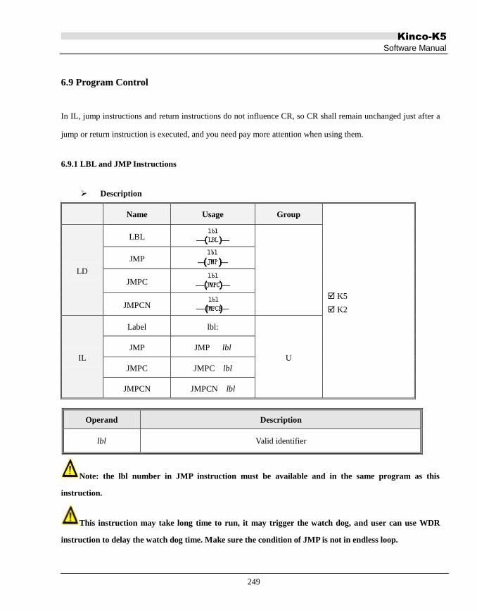
Kinco-K5
Software Manual
249
6.9 Program Control
In IL, jump instructions and return instructions do not influence CR, so CR shall remain unchanged just after a
jump or return instruction is executed, and you need pay more attention when using them.
6.9.1 LBL and JMP Instructions
Description
Name Usage Group
K5
K2
LD
LBL
JMP
JMPC
JMPCN
IL
Label lbl:
U
JMP JMP lbl
JMPC JMPC lbl
JMPCN JMPCN lbl
Note: the lbl number in JMP instruction must be available and in the same program as this
instruction.
This instruction may take long time to run, it may trigger the watch dog, and user can use WDR
instruction to delay the watch dog time. Make sure the condition of JMP is not in endless loop.
Operand Description
lbl Valid identifier

Kinco-K5
Software Manual
250
Note: the execution of return instruction does not affect the CR value. If it is necessary, user should
build new CR value before the return point to avoid the program execution error.
LD
The LBL instruction is used to define a label at the current position, and the label will function as the destination
for the jump instructions. Redefinition of a label identifier is forbidden. This instruction is executed
unconditionally, so you need not add any elements on its left. Actually, KincoBuilder will ignore all the
elements on its left.
The JMP instruction is used to unconditionally transfer program execution to the network label specified by lbl.
The JMPC instruction is used to transfer program execution to the network label specified by lbl when the
horizontal link state on its left is true.
The JMPCN instruction is used to transfer program execution to the network label specified by lbl when the
horizontal link state on its left is false.
The jump instruction and its destination label must always exist within the same POU.
IL
The definition format of a label is a legal identifier: The definition occupies an independent line. Redefinition
of a label identifier is forbidden.
The JMP instruction is used to unconditionally transfer program execution to the label specified by lbl.
The JMPC instruction is used to transfer program execution to the label specified by lbl when CR is 1.
The JMPCN instruction is used to transfer program execution to the label specified by lbl when CR is 0.
The jump instruction and its destination label must always exist within the same POU.

Kinco-K5
Software Manual
251
Examples
LD IL
.
.
.
(* NETWORK 0 *)
test:
...
(* NETWORK 4 *)
LD %I0.0
R_TRIG
JMPC test

Kinco-K5
Software Manual
252
6.9.2 Return Instructions
Notice: Return instructions can only be used in subroutines and interrupt routines.
Description
Name Usage Group
K5
K2
LD
RETC
RETCN
IL
RETC RETC
U
RETCN RETCN
LD
The RETC instruction is used to terminate a subroutine or an interrupt routine and transfer program execution
back to the calling entry when the horizontal link state on its left is true.
The RETCN instruction is used to terminate a subroutine or an interrupt routine and transfer program execution
back to the calling entry when the horizontal link state on its left is false.
IL
The RETC instruction is used to terminate a subroutine or an interrupt routine and transfer program execution
back to the calling entry when CR is 1.
The RETCN instruction is used to terminate a subroutine or an interrupt routine and transfer program execution
back to the calling entry when CR is 0.
Note: the execution of return instruction does not affect the CR value. If it is necessary, user should
build new CR value before the return point to avoid the program execution error.
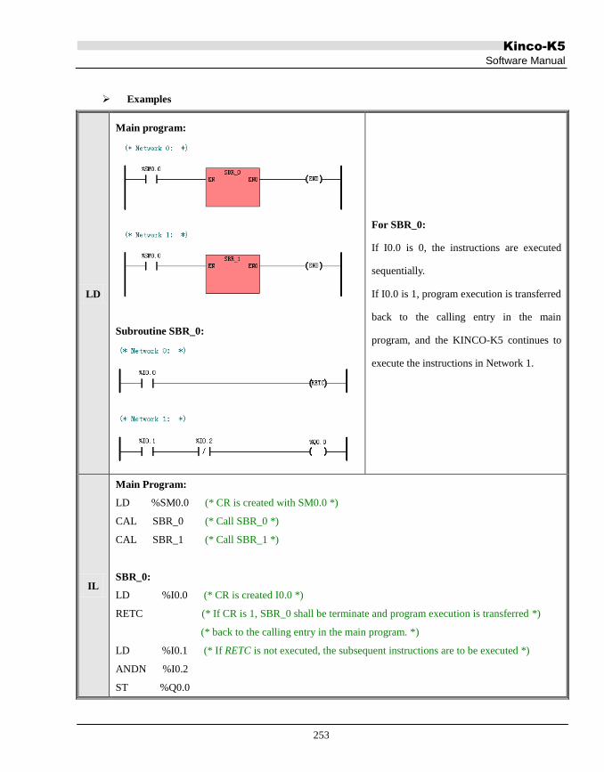
Kinco-K5
Software Manual
253
Examples
LD
Main program:
Subroutine SBR_0:
For SBR_0:
If I0.0 is 0, the instructions are executed
sequentially.
If I0.0 is 1, program execution is transferred
back to the calling entry in the main
program, and the KINCO-K5 continues to
execute the instructions in Network 1.
IL
Main Program:
LD %SM0.0 (* CR is created with SM0.0 *)
CAL SBR_0 (* Call SBR_0 *)
CAL SBR_1 (* Call SBR_1 *)
SBR_0:
LD %I0.0 (* CR is created I0.0 *)
RETC (* If CR is 1, SBR_0 shall be terminate and program execution is transferred *)
(* back to the calling entry in the main program. *)
LD %I0.1 (* If RETC is not executed, the subsequent instructions are to be executed *)
ANDN %I0.2
ST %Q0.0

Kinco-K5
Software Manual
254
6.9.3 CAL (Call a subroutine)
Description
Name Usage Group
K5
K2
LD CAL
IL CAL CAL subroutine, subroutine 1,
subroutine 2, … U
This instruction is used for calling and executing a subroutine with the specified NAME. The subroutine to be
called must exist in the user program already.
You can use a CAL instruction with or without parameters.If a CAL instruction is used with parameters, the data
type and the variable type of the actual parameters, must match those of the formal parameters which are defined
in the Local Variable Table of the called subroutine. Also, the order of the actual parameters must be the same as
that of the the formal parameters.
LD
All the names of the subroutines appear in the group [SBR] of the [LD instructions] tree. Double click on a
name, then the corresponding subroutine is added into you program. If EN is 1, this subroutine is executed.
IL
If CR is 1, the subroutine will be called and executed.
The CAL instruction does not influence CR, but CR may be changed in the subroutine.

Kinco-K5
Software Manual
255
Examples
LD
Main program:
The Local Variable Table of the subroutine 'Initialize':
In main program:
If I0.0= 0,it jumps
the subroutine, and
continues to execute
following
instructions
sequentially.
If I0.0=1,it will call
and execute
subroutine
“Initialize”.
IL
Main Program:
(* Network 0 *)
(*call the subroutine 'Initialize'*)
LD %I0.0 (*CR is created with SM0.0 *)
CAL Initialize, %M0.0, %VB0, %VW2, %VR10 (*If CR is 1, Call and execute the Intialize *)
The Local Variable Table of the subroutine 'Initialize':

Kinco-K5
Software Manual
256
6.9.4 FOR/NEXT ( FOR/NEXT Loop)
Description
Name Usage Group
K5
K2
LD
FOR
NEXT
IL
FOR FOR INDX, INIT, FINAL
U
NEXT NEXT
Operands Input/Output Data Type Acceptable Memory Areas
INDX Input INT M, V, L, SM
INIT Input INT M, V, L, SM, T, C, Constant
FINAL Output INT M, V, L, SM, T, C, Constant
This instruction may take long time to run, it may trigger the watch dog, and user can use WDR
instruction to delay the watch dog time.
Note: the FINAL parameter cannot equal to 32767 and INIT must smaller than or equal
to FINAL, for example:
INIT = 0, FINAL = 0, execute 1 time;
INIT = -1, FINAL = 0, execute 2 times;
INIT = 32766, FINAL = 32766, execute 1 time;
INIT = -32768, FINAL = -32767, execute 2 times;
INIT = 0, FINAL = 32766, execute 32767 times;
INIT = -32768, FINAL = 32766, execute 65535 times;

Kinco-K5
Software Manual
257
INIT = 3, FINAL = 2, Do not execute; (Error, INIT is larger than FINAL).
INIT = -2, FINAL = -3, Do not execute; (Error, INIT is larger than FINAL)
INIT = 1, FINAL = 32767, Do not execute; (Error, the FINAL parameter cannot equal to 32767)
INIT = -32768, FINAL = 32767, Do not execute; (Error, the FINAL parameter cannot equal to
32767)
The FOR/NEXT instructions express a loop that is repeated for the specified count. You specify the loop count
(INDX), the starting value (INIT), and the ending value (FINAL).
The NEXT instruction marks the end of the loop, and the FOR instruction executes the instructions between the
FOR and the NEXT. They must be used in pairs, each FOR instruction requires a NEXT instruction.
If a FOR/NEXT loop exists within another FOR/NEXT loop, it is called a nested loop. You can nest
FOR/NEXT loops to a depth of eight.
The execution process of the FOR/NEXT loop is shown in the following figure:

Kinco-K5
Software Manual
258
INDX = INIT
Execute the instructions between
the FOR and the NEXT
INDX > FINAL ?
INDX = INDX + 1
Continue to execute the instructions after the loop
Y
N
When using the FOR/NEXT instructions, you need to notice the following details:
The FOR instruction must be the 2nd instruction within a Network.
The NEXT instruction must monopolize a Network.
You can change the final value from within the loop itself to change the end condition of the loop.
A loop, which needs to execute for a long time that exceed the CPU‟s watchdog time, can leads to the
CPU restarting.
LD
If EN is 1, this instruction is executed.
IL
If CR is 1, this instruction is executed, and it does not influence CR.

Kinco-K5
Software Manual
259
Example
LD
IL
(* Network 0 *)
(*On the rising edge of I0.0, the loop is executed for 100 times*)
LD %I0.0
R_TRIG
ST %M0.0
(* Network 1 *)
LD %M0.0
FOR %VW0, 1, 100
(* Network 2 *)
LD %SM0.0
INC %VW100
(* Network 3 *)
LD TRUE
NEXT

Kinco-K5
Software Manual
260
6.9.5 END (Terminate the scan cycle)
Description
Name Usage Group
K5
K2
LD END
IL END END U
This instruction can only be used in the main program, for terminating the current scan cycle.
At the end of the main program, KincoBuilder automatically calls the END instruction implicitly.
LD
If the horizontal link state on its left is 1, this instruction is executed. Otherwise, this instruction does not take
effect.
IL
If CR is 1, this instruction will be executed. Otherwise, this instruction does not take effect.
This instruction does not influence CR.

Kinco-K5
Software Manual
261
6.9.6 STOP (Stop the CPU)
Description
Name Usage Group
K5
K2
LD STOP
IL STOP STOP U
This instruction terminates the execution of your program and turns the CPU from RUN into STOP mode
immediately.
LD
If the horizontal link state on its left is 1, this instruction is executed. Otherwise, this instruction does not take
effect.
IL
If CR is 1, this instruction is executed. Otherwise, this instruction does not take effect.
This instruction does not influence CR.

Kinco-K5
Software Manual
262
6.9.7 WDR (Watchdog Reset)
Description
Name Usage Group
K5
K2
LD WDR
IL WDR WDR U
This instruction re-triggers the system watchdog timer of the CPU.
Using the WDR instructin can increase the time that the scan cycle is allowed to take without leading to a
watchdog error, so the program that needs longer time can be executed successfully. But you should use this
instruction carefully, because the following processes are inhibited until the scan cycle is completed:
CPU self-diagnosis
Read the inputs (sample all the physical input channels and writes these values to the input image areas)
Communication
Write to the outputs (write the values stored in the output image areas to the physical output channels)
Timing for the 10-ms and 100-ms timers
LD
If the horizontal link state on its left is 1, this instruction is executed. Otherwise, this instruction does not take
effect.
IL
If CR is 1, this instruction is executed. Otherwise, this instruction does not take effect.
This instruction does not influence CR.

Kinco-K5
Software Manual
263
6.10 Interrupt Instructions
The purpose of using interrupt technique is to increase the execution efficiency of the Kinco-K5 to quickly
respond to special internal or external predefined events. The Kinco-K5 supports tens of events each of which is
assigned with a unique event number.
6.10.1 How K5 handles Interrupt Routines
An interrupt routine is executed once only on each occurrence of the interrupt event associated with it. Once the
last instruction of the interrupt routine has been executed, program execution is transferred back to the main
program. You can exit the routine by executing a RETC or RETCN instruction.
Interrupt technique makes the Kinco-K5 respond to special events quickly, so you should optimize interrupt
routines to be short and efficient.
6.10.2 Interrupt Priority and Queue
Different events are on different priority levels. When interrupt events occur, they will queue up according to
their priority levels and time sequence: the interrupt events in the same priority group are handled following the
principle of “first come, first served”; the events in the higher priority group are handled preferentially. Only
one interrupt routine can be executed at one point in time. Once an interrupt routine begins to be executed, it
cannot be interrupted by another interrupt routine. Interrupt events that occur while another interrupt routine is
being executed are queued up for later handling.
6.10.3 Types of Interrupt Events Supported by the Kinco-K5
The Kinco-K5 supports the following types of interrupt events:
Communication Port Interrupts
This type of interrupts has the highest priority.

Kinco-K5
Software Manual
264
They are used for free-protocol communication mode. The Receive and Transmit interrupts facilitate you to
fully control the communication. Please refer to the Transmit and Receive instructions for detailed information.
I/O Interrupts
This type of interrupts has a medium priority.
These interrupt include rising/falling edge interrupts, HSC interrupts and PTO interrupts.
The rising/falling edge interrupts can only be trapped by the first four DI channels (%I0.0~%I0.3) on the CPU
body. Each of them can be used to notify that the signal state has changed and the PLC must respond
immediately.
The HSC interrupts occur when the counting value reaches the preset value, the counting direction changes or
the counter is reset externally. Each of them allows the PLC respond in real time to high-speed events that
cannot be responded immediately at scan speed.
The PTO interrupts occur immediately when outputting the specified number of pulses is completed. A typical
application is to control the stepper motor.
Time Interrupts
This type of interrupts has the lowest priority.
These interrupt include timed interrupts and the timer T2 and T3 interrupts.
The timed interrupts occur periodically (unit: 0.1ms), and they can be used for periodical tasks. (the period of
these interrupts period will not be affected by plc scanning time.)
The timer interrupt occurs immediately when the current value of T2 or T3 reaches the preset value. It can be
used to timely respond to the end of a specified time interval. ( the period of these interrupts period will be
affected by plc scanning time.)
6.10.4 Interrupt Events List
Event No. Description Type
34 PORT 2: XMT complete Communication

Kinco-K5
Software Manual
265
33 PORT 2: RCV complete Port Interrupts
32 PORT 1: XMT complete
31 PORT 1: RCV complete
30 PORT 0: XMT complete
29 PORT 0: RCV complete
28~27 Reserved
I/O Interrupts
26 I0.0, Falling edge
25 I0.0, Rising edge
24 I0.1, Falling edge
23 I0.1, Rising edge
22 I0.2, Falling edge
21 I0.2, Rising edge
20 I0.3, Falling edge
19 I0.3, Rising edge
18 HSC0 CV=PV
17 HSC0 direction changed
16 HSC0 external reset
15 HSC1 CV=PV
14 HSC1 direction changed
13 HSC1 external reset
12~5 Reserved
4 Timed interrupt 1. Its period is specified in SMD16, unit:
0.1ms.( Doesn't be affected by scan cycle)
Time Interrupts 3 Timed interrupt 0. Its period is specified in SMD12, unit: 0.1ms.
( Doesn't be affected by scan cycle)
2 Timer T3 ET=PT( Doesn't be affected by scan cycle)
1 Timer T2 ET=PT( Doesn't be affected by scan cycle)
Table 6-1 Interrupt Events
Event 3(Timed interrupt 0)/Event 4(Timed interrupt 1) regardless of PLC scanning clcyle, but is
influenced by higher priority hardware interrupts. When testing revolving speed and flow, long
duration timing is required, users could make compensation according to application.

Kinco-K5
Software Manual
266
Event 1/2 are influenced by PLC scanning cycle. Event 3/4 are recommended for accurate timing.
6.10.5 ENI (Enable Interrupt), DISI (Disable Interrupt)
Description
Name Usage Group
K5
K2
LD
ENI
DISI
IL
ENI ENI
U
DISI DISI
The ENI instruction globally enables processing all attached interrupt events.
The DISI instruction globally inhibits processing all interrupt events.
ENI and DISI just execute once.
All interrupts are enabled being processed by default.
LD
If the horizontal link state on its left is 1, the instruction is executed. Otherwise, the instruction does not take
effect.
IL
If CR is 1, the instruction is executed. Otherwise, the instruction does not take effect.
The instruction does not influence CR.

Kinco-K5
Software Manual
267
6.10.6 ATCH and DTCH Instructions
Description
Name Usage Group
K5
K2
LD
ATCH
DTCH
IL
ATCH ATCH INT, EVENT
U
DTCH DTCH EVENT
LD
If EN is 1, the ATCH instruction attaches an interrupt event (specified by the event number EVENT) to the
interrupt routine (specified by the routine name INT) and enables the interrupt event. After this instruction is
executed, the interrupt routine shall be invoked automatically on the occurrence of the interrupt event. You can
attach several events to one interrupt routine, but one event can only be attached to one interrupt routine.
If EN is 1, the DTCH instruction breaks the attachment between the interrupt event (specified by the event
number EVENT) and its interrupt routine, and makes the interrupt event return to be disabled.
IL
If CR is 1, the ATCH instruction attaches an interrupt event (specified by the event number EVENT) to the
Operands Input/Output Data Type Description
INT Input Identifier The name of an existing interrupt routine
EVENT Input INT Constant, an interrupt event No.

Kinco-K5
Software Manual
268
interrupt routine (specified by the routine name INT) and enables the interrupt event. This instruction does not
influence CR.
If CR is 1, the DTCH instruction breaks the attachment between the interrupt event (specified by the event
number EVENT) and its interrupt routine, and makes the interrupt event return to be disabled. This instruction
does not influence CR.
Examples
LD
IL
(* NETWORK 0 *)
LD %SM0.1
ATCH INT_0, 25
LD %M5.0
DTCH 25
(*On the first scan, No.25 event is enabled and attached to INT_0 routine *)
(* CR is created with M5.0 *)
(*If CR is 1, disable No.25 event *)
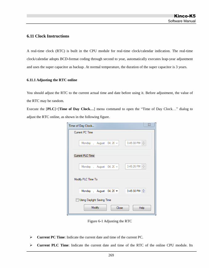
Kinco-K5
Software Manual
269
6.11 Clock Instructions
A real-time clock (RTC) is built in the CPU module for real-time clock/calendar indication. The real-time
clock/calendar adopts BCD-format coding through second to year, automatically executes leap-year adjustment
and uses the super capacitor as backup. At normal temperature, the duration of the super capacitor is 3 years.
6.11.1 Adjusting the RTC online
You should adjust the RTC to the current actual time and date before using it. Before adjustment, the value of
the RTC may be random.
Execute the [PLC]>[Time of Day Clock…] menu command to open the “Time of Day Clock…” dialog to
adjust the RTC online, as shown in the following figure.
Figure 6-1 Adjusting the RTC
Current PC Time: Indicate the current date and time of the current PC.
Current PLC Time: Indicate the current date and time of the RTC of the online CPU module. Its

Kinco-K5
Software Manual
270
background being green indicates that the CPU module communicates with the PC successfully, and its
background being yellow indicates the CPU module fails to communicate with the PC.
Modify PLC Time To: You can enter the desired date and time for the RTC here. Enter them through
keyboard, or click the arrowhead at the right end of the relevant box to select the date or adjust the time.
Daylight Saving Time: You may click this item when needed.
Modify: Click this button, the date and time you have entered shall be written into the CPU module, and
then the RTC shall be adjusted to the desired date and time.
NOTE: If Daylight Saving Time is adopted it is required to reboot Kincobuilder to take
effect.
In the time zone which adopts Daylight Saving Time, windows let users select whether
windows handle Daylight Saving Time automatically. If choose "automatically adjust clock
for Daylight Saving Time, users have tochoose "Daylight Saving Time" in Kincobuilder. Or
users do not choosed both in windows and in Kincobuilder.
Do not choose "Daylight Saving Time" in Kincobuilder if users' time zone do not apply
daylight saving time.

Kinco-K5
Software Manual
271
6.11.2 READ_RTC and SET_RTC
Description
Name Usage Group
□ CPU504
CPU504EX
CPU506
CPU506EA
CPU508
K2
LD
READ_RTC
SET_RTC
IL
READ_RTC READ_RTC T
U
SET_RTC SET_RTC T
Note: the T parameter is memory block whose length is changeable. The whole block cannot be in
the illegal area, or there will be unpredictable result.
The READ_RTC instruction is used to read the current date and time from the RTC and write them to an 8-byte
time buffer beginning with address T.
The SET_RTC instruction is used to write the date and time specified by the 8-byte time buffer beginning with
address T to the RTC.
The storage format of the date and time in the time buffer is shown in the following table.
Note: All the values are of BCD coding.
V Byte Meaning Remark
T Week Range: 1~7, thereof 1 represents Monday, 7 represents Sunday.
Operands Input/Output Data Type Acceptable Memory Areas
T
Input (SET_RTC)
BYTE V
Output (READ_RTC)

Kinco-K5
Software Manual
272
T+1 Second Range: 0~59
T+2 Minute Range: 0~59
T+3 Hour Range: 0~23
T+4 Day Range: 1~31
T+5 Month Range: 1~12
T+6 Year Range: 0~99
T+7 Century Fixed as 20
Table 6-2 The Time Buffer
Notice:
You are recommended to adjust the RTC correctly using [PLC]>[Time of Day Clock…] menu
command before using it.
Because the CPU module won’t check the validity of the date and time you have entered and
invalid data (e.g. Feb 30) will be accepted. Therefore, you have to ensure the validity of the
date/time you have entered.
LD
If EN is 1, this instruction is executed.
IL
If CR is 1, this instruction is executed, and it does not influence CR.
Examples

Kinco-K5
Software Manual
273
LD
IL
(* Network 0 *)
(*Read the RTC every 1 second*)
LD %SM0.3
R_TRIG
READ_RTC %VB0
(* Network 1 *)
(*Turn on Q0.0 during 9:00-18:00 everyday, and turn off it at other time.*)
LD %SM0.0
GE %VB3, B#16#9
LT %VB3, B#16#18
ST %Q0.0

Kinco-K5
Software Manual
274
6.11.3 RTC_R
Description
Name Usage Group
□ CPU504
CPU504EX
CPU506
CPU506EA
CPU508
K2
LD RTC_R
IL RTC_R RTC_R FMT, WEEK, SECOND, MINUTE,
HOUR, DAY, MONTH, YEAR, CENTURY U
Operands Input/Output Data Type Acceptable Memory Areas
FMT Input BYTE L, M, V, Constants
WRRK Output BYTE L, M, V
SECOND Output BYTE L, M, V
MINUTE Output BYTE L, M, V
HOUR Output BYTE L, M, V
DAY Output BYTE L, M, V
MONTH Output BYTE L, M, V
YEAR Output BYTE L, M, V
CENTURY Output BYTE L, M, V

Kinco-K5
Software Manual
275
You may refer to the table below to see the parameters:
Operands Description
EN Enable
FMT Output Format. 0 represents decimal and 1 represents BCD code
WRRK Week. 1-7 represents Mon to Sun
SECOND Second, ranging from 0-59
MINUTE Minute, ranging from 0-59
HOUR Hour, ranging from 0-23
DAY Day, ranging from 1-31
MONTH Month, ranging from 1-12
YEAR Year, ranging from 0-99
CENTURY Century, a fixed value of 20
The RTC_R instruction is used to read the current date and time from the RTC and write them into the
corresponding output parameters.
FMT represents the format of each parameter; 0 represents decimal and 1 represents BCD code.
LD
If EN is 1, this instruction is executed.
IL
If CR is 1, this instruction is executed.
This instruction will not affect CR value.

Kinco-K5
Software Manual
276
6.11.4 RTC_W
Description
Name Usage Group
□ CPU504
CPU504EX
CPU506
CPU506EA
CPU508
K2
LD RTC_W
IL RTC_W RTC_W FMT, WEEK, SECOND, MINUTE,
HOUR, DAY, MONTH, YEAR, CENTURY U
Operands Input/Output Data Type Acceptable Memory Areas
FMT Input BYTE L, M, V, Constants
WRRK Input BYTE L, M, V , Constants
SECOND Input BYTE L, M, V, Constants
MINUTE Input BYTE L, M, V, Constants
HOUR Input BYTE L, M, V, Constants
DAY Input BYTE L, M, V, Constants
MONTH Input BYTE L, M, V, Constants
YEAR Input BYTE L, M, V, Constants
CENTURY Input BYTE L, M, V, Constants

Kinco-K5
Software Manual
277
FMT, WEEK, SECOND, MINUTE, HOUR, DAY, MONTH, YEAR and CENTURY must be constant or
memory register at the same time. You may refer to the table below to see the parameters:
Operands Description
EN Enable
FMT Output Format. 0 represents decimal and 1 represents BCD code
WRRK Week. 1-7 represents Mon to Sun
SECOND Second, ranging from 0-59
MINUTE Minute, ranging from 0-59
HOUR Hour, ranging from 0-23
DAY Day, ranging from 1-31
MONTH Month, ranging from 1-12
YEAR Year, ranging from 0-99
CENTURY Century, a fixed value of 20
The RTC_W instruction is used to write the date and time specified by the corresponding input parameters into
the RTC.
the FMT represents the format of each parameter; 0 represents decimal and 1 represents BCD code.
LD
If EN is 1, this instruction is executed.
IL
If CR is 1, this instruction is executed.
This instruction will not affect CR value.

Kinco-K5
Software Manual
278
6.12 Communication Instructions
6.12.1 Free-protocol Communication
These instructions are used for free-protocol communication. Free-protocol communication mode allows your
program to entirely control the communication ports of the CPU. You can use free-protocol communication
mode to implement user-defined communication protocols to communicate with all kinds of intelligent devices.
ASCII and binary protocols are both supported.
The CPU module is integrated with 1, 2 or 3 communication ports, each of that serves as a default Modbus RTU
slave. After the communication instructions are executed, free-protocol communication mode shall be activated,
involving no manual operation.
You can configure the communication parameters (such as Baudrate, Parity, etc) of each port in the Hardware
Window. Please refer to 4.3.4.1 Parameters of the CPU for detailed information.
The general procedure to execute the Free-protocol Communication programming:
Set the port communication parameter (including station number, baud rate, even-odd check, etc.) of the
communication port of the 【PLC Hardware Configuration】. For more detail please refer to 4.3.4.1
Parameters of the CPU.
Set the free communication control register (see definition in following clauses). NOTE: the control
register must be set ready in prior.
Call XMT and RCV command and program as status register and communication interruption of the free
communication.

Kinco-K5
Software Manual
279
6.12.2 XMT and RCV
Description
Name Usage Influence
K5
K2
LD
XMT
RCV
IL XMT XMT TBL, PORT
U RCV RCV TBL, PORT
Note: the TBL parameter is memory block whose length is changeable. The whole block cannot be in
the illegal area, or there will be unpredictable result.
Note: After call RCV instruction, if no bytes are received by serial port, it will generate a 60s
system timeout and finish RCV. Timeout set by users only be triggerred when at least one byte is
received.
The XMT instruction is used to transmit the data stored in a data buffer through the communication port
specified by PORT in free-protocol communication mode. The data buffer begins with address TBL, and the
first byte specifies the number of bytes to be transmitted, then followed with the effective data. If SM87.1=1,
when the CPU has transmitted the last character in the data buffer, there will automatically occur a
XMT-complete interrupt event (the event number is 30 for PORT 0, and 32 for PORT 1). If the number of bytes
Operands Input/Output Data Type Acceptable Memory Areas
TBL Input BYTE I, Q, M, V, L, SM
PORT Input INT Constant (0 to 2)

Kinco-K5
Software Manual
280
to be transmitted is set to be 0, the XMT instruction won‟t execute any operation, and of course, the interrupt
event won‟t occur.
The RCV instruction is used to receive data through the communication port specified by PORT in free-protocol
communication mode, and the data received shall be stored in a data buffer. The data buffer begins with address
TBL, and the first byte specifies the number of bytes received, then followed with the effective data received.
You must specify a Start and and End condition for the RCV operation. If SM87.1=1, when the CPU completes
receiving (disregarding normal or abnormal completion), there will automatically occur a RCV-complete
interrupt event (the event number is 29 for PORT 0, and 31 for PORT 1).
In LD, the EN input decides whether to execute the XMT and RCV instructions. If EN is 1 then XMT and RCV
instructions will be executed and vice versa;
In IL, CR decides whether to execute the XMT and RCV instructions. If CR is 1 then XMT and RCV
instructions will be executed and vice versa; they won‟t influence CR.
Status Registers and Control Registers in SM area for Free-protocol Communication
Besides XMT and RCV instructions, some status registers and control registers in SM area are provided for
free-protocol communication. Your program can read and write to these registers to interpret the communication
status and control the communication. The following is the brief summary of status bytes and control words.
SMB86 --- Receive Status Register
Bit (read-only) Status Description
PORT 0 PORT 1 PORT 2
SM86.0 SM186.0 SM286.0 1 A parity error is detected, but receive shall not be terminated.
SM86.1 SM186.1 SM286.1 1 Receive was terminated because of receiving the maximum
character number.
SM86.2 SM186.2 SM286.2 1 Receive was terminated because of receiving a character
Overtime.
SM86.3 SM186.3 SM286.3 1 Receive was terminated because of System Overtime.
SM86.4 SM186.4 SM286.4 - Reserved.
SM86.5 SM186.5 SM286.5 1 Receive was terminated because of receiving the user-defined

Kinco-K5
Software Manual
281
End character.
SM86.6 SM186.6 SM286.6 1 Receive was terminated because of the errors in the parameters
or missing the Start or End condition.
SM86.7 SM186.7 SM286.7 1 Receive was terminated because of the user disable command.
SMB87 --- Receive Control Register
Bit Status Description
PORT 0 PORT 1 PORT 2
SM87.0 SM187.0 SM287.0 - Reserved.
SM87.1 SM187.1 SM287.1 0 Disenable XMT-complete and RCV-complete interrupts.
1 Enable XMT-complete and RCV-complete interrupts.
SM87.2 SM187.2 SM287.2
0 Ignore SMW92/ SMW192/SMW292.
1 Terminate receive if the time in SMW92/ SMW192/SMW292
is exceeded while receiving a character.
SM87.3 SM187.3 SM287.3 - Reserved.
SM87.4 SM187.4 SM287.4
0 Ignore SMW90/ SMW190/ SMW290.
1 Turn to effective receive if the time interval in SMW90/
SMW190/SMW290 is exceeded.
SM87.5 SM187.5 SM287.5
0 Ignore SMB89/ SMB189/ SMB289.
1 Enable the user-defined End character in SMB89/ SMB189/
SMB289.
SM87.6 SM187.6 SM287.6
0 Ignore SMB88/ SMB188/ SMB288.
1 Enable the user-defined Start character in SMB88/SMB188/
SMB288
SM87.7 SM187.7 SM287.7
0 Disenable RCV function.
This condition prevails over any other conditions.
1 Enable RCV function.
Other Control Registers
PORT 0 PORT 1 PORT 2 Description
SMB88 SMB188 SMB288 To store the user-defined receive Start character.

Kinco-K5
Software Manual
282
After executing the RCV instruction, the CPU turns into effective
receive state when the Start character is received, and the previously
received data will be rejected. CPU takes the Start character as the first
effective byte received.
SM87.6/ SM187.6/ SM287.6 should be set to be 1 to enable SMB88/
SMB188/ SMB288.
SMB89 SMB189 SMB289
To store the user-defined receive End character.
The CPU will take this character as the last effective byte received.
When the character is received, the CPU will immediately terminate
receive disregarding any other End conditions.
SM87.5/ SM187.5/ SM287.5 should be set to be 1 to enable SMB89/
SMB189/ SMB289.
SMW90 SMW190 SMW290
To store the user-defined receive Ready time (Range: 1~60,000ms).
After executing the RCV instruction and passing through this time
interval, the CPU will automatically turn into effective receive state
disregarding whether the Start character is received or not. Thereafter,
the data received shall be effective.
SM87.4/SM287.4/ SM287.4 should be set to be 1 to enable SMW90/
SMW190/ SMW290.
SMW92 SMW192 SMW292
To store the user-defined receiving a character Overtime (Range:
1~60,000ms).
After executing the RCV instruction and turning into effective receive
state, if no character is received within this time interval, the CPU will
terminate receive disregarding any other End condition.
SM87.2/SM187.2/SM287.2 should be set to be 1 to enable SMW92/
SMW192/ SMW292.
SMW94 SMW194 SMW294
To store the maximum number of characters to be received (1~255).
The CPU will immediately terminate receive as soon as the maximum
effective characters are received disregarding any other End conditions.
If this value is set to be 0, the RCV instruction will return directly.
In free-protocol communication mode, there is a default System Receive Overtime (90 seconds). This overtime
value functions as the following: After executing the RCV instruction, the CPU will immediately terminate

Kinco-K5
Software Manual
283
receive if no data is received during this time interval. Besides, when the CPU turns into effective receive state,
it will use the value of the receiving a character Overtime defined in SMW92 first, and if no valid value is in
SMW92, the value of System Receive Overtime will be used as a substitute.
Communication Interruption
Kinco-K5 offers variable interruption for free communications. If you would like to know more detail
information, please refer to 6.10.1 How the Kinco K5 Handle Interruption Routines.
You may use SM87.1, SM187.1 or SM287.1 to allow or forbid CPU to interrupt communication. The
interruption control set to 1 represent an allow routine; CPU will generate an interruption of sending completion
when complete send the last word in buffer area; CPU will generate an interruption of receive completion when
quit receiving (regardless of normal or abnormal quit).
Examples
Examples are given below to illustrate the application of the free-protocol communication mode. In the example,
the CPU will receive a character string, taking RETURN character as the receive End character; if receive is
completed normally, the data received is transmitted back and receive is restarted, if receive is completed
abnormally (e.g. because of communication errors, time out, etc), the data received will be ignored and receive
will be restarted.

Kinco-K5
Software Manual
284
LD
MAIN Program:

Kinco-K5
Software Manual
285
LD
EndReceive (INT00): The RCV-complete interrupt routine
EndSend (INT01): XMT-complete interrupt routine

Kinco-K5
Software Manual
286
IL
MAIN Program:
(* Network 0 *)
(* The following program is to initialize free-protocol communication. *)
(* At first, configure the Start and End conditions of the effective Receive state. *)
LD %SM0.1
MOVE B#16#B6, %SMB87
(* Network 1 *)
(* The receive Ready time is set to be 10ms, *)
(* The receive End character is set to be RETURN character whose ASCII is 13. *)
LD %SM0.1
MOVE 10, %SMW90
MOVE B#16#D, %SMB89
(* Network 2 *)
(* The receiving a character Overtime is set to be 500ms, *)
(* The maximum number of characters to be received is set to be 100. *)
LD %SM0.1
MOVE 500, %SMW92
MOVE B#100, %SMB94
(* Network 3 *)
(* Attach the RCV-complete event to the EndReceiver routine, *)
(* Attach the XMT-complete event to the EndSendroutine *)
LD %SM0.1
ATCH EndReceive, 29
ATCH EndSend, 30
(* Network 4 *)
(* Start the Receive task once on the first scan. *)
LD %SM0.1
RCV %VB100, 0

Kinco-K5
Software Manual
287
EndReive (INT00): The RCV-complete interrupt routine
(* Network 0 *)
(* If receiving the receive End character, then transmit bach the data received and return. *)
LD %SM86.5
XMT %VB100, 0
RETC
(* Network 1 *)
(* if receive is completed abnormally, then restart receive. *)
LD %SM86.6
OR %SM86.3
OR %SM86.2
OR %SM86.1
OR %SM86.0
RCV %VB100, 0
EndSend (INT01): XMT-complete interrupt routine
(* Network 0 *)
(* Restart receive after the transmition is completed. *)
LD TRUE
RCV %VB100, 0

Kinco-K5
Software Manual
288
6.12.3 Modbus RTU Master Instructions
The Modbus RTU protocol is widely used in the industrial field. The KINCO-K5 provides the Modbus RTU
Master instructions, and you can call them directly to make the KINCO-K5 as a Modbus RTU master.
Note: these instructions are supported by PORT1 and PORT2.
The general steps of the Modbus master programming are described as followings:
Configure the communication parameters of Port1 in the Hardware Window. Please refer to 2.6 How to
modify the CPU‟s communication parameters and 4.3.4.1 Parameters of the CPU for more details.
Call the instructions MBUSR and MBUSW in the program.
Please refer to Appendix A 2、Basic Report Format of Modbus RTU Protocal for more details about
Modbus RTU.

Kinco-K5
Software Manual
289
6.12.3.1 MBUSR (Modbus RTU Master Read)
Description
Name Usage Group
□ CPU504
CPU504EX
CPU506
CPU506EA
CPU508
K2
LD MBUSR
IL MBUSR MBUSR EXEC, PORT, SLAVE, FUN, ADDR,
COUNT, READ, RES U
Operands Input/Output Data Type Acceptable Memory Areas
EXEC Input BYTE I, Q, V, M, L, SM, RS, SR
PORT Input INT Constant (0~2)
SLAVE Input BYTE I, Q, M, V, L, SM, Constant
FUN Input INT Constant (MODBUS function code)
ADDR Input INT I, Q, M, V, L, SM, AI, AQ, Constant
COUNT Input INT I, Q, M, V, L, SM, AI, AQ, Constant
READ Output BOOL, WORD, INT Q, M, V, L, SM, AQ
RES Output BYTE Q, M, V, L, SM
The "SLAVE, ADDR, COUNT" should be constants or variables at the same time. Range of COUNT is
1~32. It takes 32 automatically when COUNT is set larger value than 32.
Note: the READ parameter is memory block whose length is changeable. The whole block cannot be
in the illegal area, or there will be unpredictable result.
This instruction is used for reading data from a slave. The available function codes include 1 (read DO status), 2

Kinco-K5
Software Manual
290
(read DI status), 3 (read AO data) and 4 (Read AI data).
The parameter PORT defines the communication port used. The SLAVE defines the target slave address, whose
available range is 1~255. The FUN defines a valid function code. The ADDR defines the starting address of the
Modbus register to be read. The COUNT defines the number (Max. 32) of the registers to be read.
The rising edge of EXEC is used for starting the communication. While a MBUSR instruction is executed, it
will communicate for one time on the rising edge of EXEC: Organize a Modbus RTU message according to the
parameters SLAVE, FUN, ADDR and COUNT, then transmit it and wait for the response of the slave; When
receiving the slave‟s response message, check the CRC, slave number and function code to decide whether the
message is correct or not, if correct, the useful data will be written into the buffer beginning with READ,
otherwise, the received message will be discarded.
The READ defines the starting address of a buffer, which stores the received data. The data type of READ must
match the function code. If the function code is of 1 or 2, the READ is of BOOL type; and if the function code is
of 3 or 4, the READ is of INT or WORD type.
The RES stores the communication status and the failure information of the current execution, and it is
read-only. It is described in the following figure.
LD
If EN is 1, this instruction is executed.
IL

Kinco-K5
Software Manual
291
If CR is 1, this instruction is executed, and it does not influence CR.

Kinco-K5
Software Manual
292
6.12.3.2 MBUSW (Modbus RTU Master Write)
Description
Name Usage Group
□ CPU504
CPU504EX
CPU506
CPU506EA
CPU508
K2
LD MBUSW
IL MBUSW MBUSW EXEC, PORT, SLAVE, FUN,
ADDR, COUNT, READ, RES U
Operands Input/Output Data Type Acceptable Memory Areas
EXEC Input BYTE I, Q, V, M, L, SM, RS, SR
PORT Input INT Constant (0~2)
SLAVE Input BYTE I, Q, M, V, L, SM, Constant
FUN Input INT Constant (MODBUS function code)
ADDR Input INT I, Q, M, V, L, SM, AI, AQ, Constant
COUNT Input INT I, Q, M, V, L, SM, AI, AQ, Constant
WRITE Input BOOL, WORD, INT I, Q, RS, SR, V, M, L, SM, T, C, AI, AQ
RES Output BYTE Q, M, V, L, SM
The "SLAVE, ADDR, COUNT" should be constants or variables at the same time. Range of COUNT is
1~32. It takes 32 automatically when COUNT is set larger value than 32.
Note: the WRITE parameter is memory block whose length is changeable. The whole block cannot
be in the illegal area, or there will be unpredictable result.

Kinco-K5
Software Manual
293
This instruction is used for writing data to a slave. The available function codes include 1 (write to a DO), 2
(write to a DI), 3 (write to an AO) and 4 (write to an AI).
The parameter PORT defines the communication port used. The SLAVE defines the target slave address, whose
available range is 1~31. The FUN defines a valid function code. The ADDR defines the starting address of the
Modbus register to be written into. The COUNT defines the number (Max. 32) of the registers.
The WRITE defines the starting address of a buffer, which stores the data to be written into the slave. The data
type of WRITE must match the function code. If the function code is of 5 or 15, the WRITE is of BOOL type;
and if the function code is of 6 or 16, the WRITE is of INT or WORD type.
The rising edge of EXEC is used for starting the communication. While a MBUSW instruction is executed, it
will communicate for one time on the rising edge of EXEC: Organize a Modbus RTU message according to the
parameters SLAVE, FUN, ADDR, COUNT and WRITE, then transmit it and wait for the response of the slave;
When receiving the slave‟s response message, check the CRC, slave number and function code to decide
whether the target slave executed the command correctly or not.
The RES stores the communication status and the failure information of the current execution, and it is
read-only. It is described in the following figure.
Bit 7 --- Indicates whether the communication has been finished or not: 0 = not finished, 1 = finished.
Bit 6 --- Reserved。
Bit 5 --- Illegal SLAVE.
Bit 4 --- Illegal COUNT.
Bit 3 --- Illegal ADDR.
Bit 2 --- 1 = The specified port is busy.
Bit 1 --- 1 = Time out
Bit 0 --- 1 = The received message is wrong because of CRC error, frame error, etc.
MSB LSB
7 6 5 4 3 2 1 0
NODE, INDEX, SUBINDEX, DATALEN must all be constants or all be variables at the same time.
LD
If EN is 1, this instruction is executed.

Kinco-K5
Software Manual
294
IL
If CR is 1, this instruction is executed, and it does not influence CR.
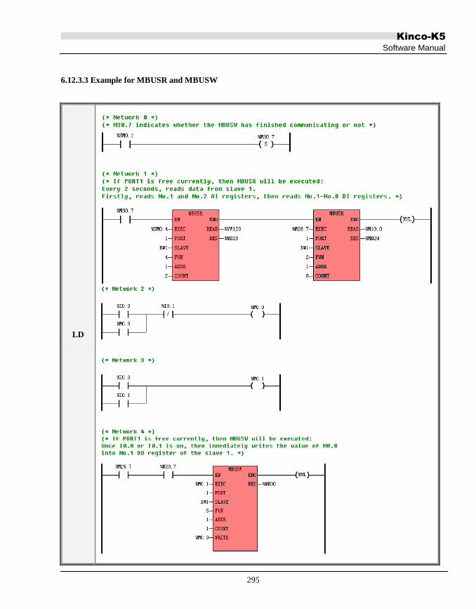
Kinco-K5
Software Manual
295
6.12.3.3 Example for MBUSR and MBUSW
LD
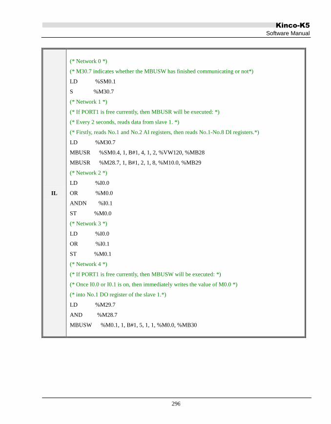
Kinco-K5
Software Manual
296
IL
(* Network 0 *)
(* M30.7 indicates whether the MBUSW has finished communicating or not*)
LD %SM0.1
S %M30.7
(* Network 1 *)
(* If PORT1 is free currently, then MBUSR will be executed: *)
(* Every 2 seconds, reads data from slave 1. *)
(* Firstly, reads No.1 and No.2 AI registers, then reads No.1-No.8 DI registers.*)
LD %M30.7
MBUSR %SM0.4, 1, B#1, 4, 1, 2, %VW120, %MB28
MBUSR %M28.7, 1, B#1, 2, 1, 8, %M10.0, %MB29
(* Network 2 *)
LD %I0.0
OR %M0.0
ANDN %I0.1
ST %M0.0
(* Network 3 *)
LD %I0.0
OR %I0.1
ST %M0.1
(* Network 4 *)
(* If PORT1 is free currently, then MBUSW will be executed: *)
(* Once I0.0 or I0.1 is on, then immediately writes the value of M0.0 *)
(* into No.1 DO register of the slave 1.*)
LD %M29.7
AND %M28.7
MBUSW %M0.1, 1, B#1, 5, 1, 1, %M0.0, %MB30

Kinco-K5
Software Manual
297
6.12.4 CANOpen and SDO
CANopen Nain Functions
Supports NMT management message
· Supports CANopen predefine connection mode, the total PDO number are 255 TxPDO
and 255 RxPDO, each salve can configure 1~8 TxPDO and 1~8 RxPDOl
· Supports 100 slaves, the slave station number are available from 10~126.
· Supports Emergency Message, Node Guide and Heartbeat Message.
· Supports configuring the boot up process of slaves
· Supports EDS file importing function
· Use SDO_WRITE and SDO_READ to operation SDO
· Supports 254 and 255 PDO transmission mode, supports sending the PDO by timed time,
it can send 8 PDO data at the same time , and the timed time can be set.
· Supports various baud rate: 10K/20K/50K/125K/250K/500K/800K/1M;
· Check the master and salve status by the PLC system register
· Supports multiple plc network communication by CAN bus
· Supports slave error handling function, when the error happens, there are three methods
optional to handle the error, they are STOP NODE, STOP NETWORD and NO OPERATION.
SDO Instruction:
SDO is used to transmit the low priority data, the typical application is used to
configure/manage the slave device. For example, it is used to change the current
loop/velocity loop/position loop parameters, PDO configuration parameters and so on. This
kind of data transmission is the same as Modbus, the slave needs to return the data to

Kinco-K5
Software Manual
298
response master. This transmission is only suitable for setting the parameters, but not
suitable for the real time data transmission. When HMI or PLC communicates with servo,
they use this method to configure the communication parameters.
SDO data format:
CAN master send the following upload instruction: 01 40 FF 60 00 00 00 00 00 60, this
instruction is to read the target speed (60FF0020) of slave
Slave Response: 01 43 FF 60 00 00 20 4E 00 EF
SDO is short for Service Data Object in CANOpen protocol. It accesses data in the dictionary of one device
through index and subindex. The visitor is called Client and the one to be visited is called Server. Client‟s
request will surely be responded by Server.
SDO is mainly used to transfer low-priority data among devices. It is suitable for configuration and
management to devices but not data transmission for data that requires high real-time performance.

Kinco-K5
Software Manual
299
6.12.4.1 SDO_WRITE
Description
Name Usage Group
□ CPU504
CPU504EX
CPU506
CPU506EA
CPU508
□ K2
LD SDO_WRITE
IL SDO_WRITE SDO_WRITE EXEC, NODE, INDEX,
SUBINDEX, DATA, DATALEN, DONE, ERROR U
Operands Input/Output Data Type Acceptable Memory Areas
EXEC Input BOOL I, Q, V, M, L, SM, RS, SR
NODE Input BYTE I, Q, V, M, L, SM, Constant
INDEX Input WORD I, Q, V, M, L, SM, Constant
SUBINDEX Input BYTE I, Q, V, M, L, SM, Constant
DATA Input BYTE I, Q, V, M, L, SM
DATALEN Input BYTE I, Q, V, M, L, SM, Constant
DONE Output BOOL Q, M, V, L, SM
ERROR Output DWORD Q, M, V, L, SM
NODE, INDEX, SUBINDEX, DATALEN should be constants or variables simultaneously.
Note: the DATA parameter is memory block whose length is changeable. The whole block cannot be
in the illegal area, or there will be unpredictable result.
Note: To use CANopen instructions, users have to also purchase CAN expension modules K541.
Third-party devices connect with K541 for CAN communication. (There is no hardware isolation for the

Kinco-K5
Software Manual
300
CAN expansion port of K5 PLC, the port is dedicated for connecting with expension modules.)
Operands Description
EN Enable. If EN is 1 then this instruction can be executed.
EXEC If EN is 1, the EXEC starts the SDO communication on the rising edge.
It is better to ensure the EN is prior to EXEC.
NODEID ID of the Node to be visited
Index Index of the object to be visited in the OD
SubIndex Subindex of the object to be visited in the OD
Data The starting address of a buffer which stores the data bytes to be sent.
DataLen Length of the data to be sent. Unit: byte.
DONE Indicates whether the instruction has finished or not.
0 = not finished; 1 = finished.
ERROR Error identification. Please see below.
Code Description
0 No errors.
1 The number of all used SDO instructions is out of limitation.
At most 72 SDO instructions (SDO_WRITE and SDO_READ) can be called in one project.
2 The Master node is not in Operational mode, so this SDO is not sent.
4 The target node does not exist or stops due to error so this SDO is not sent
6 Command parameter error.
8 The response is time-out.
The [SDO time out] value can be set in the [CANOpen]->[Global settings] tab.
9 The length of the SDO response is wrong.
10 The SDO response is wrong.
LD
If EN is 1, the rising edge of EXEC will start executing this instruction once.
IL
If CR is 1, the rising edge of EXEC will start executing this instruction once.
This instruction does not influence CR.

Kinco-K5
Software Manual
301
6.12.4.2 SDO_READ
Description
Name Usage Group
□ CPU504
CPU504EX
CPU506
CPU506EA
CPU508
□ K2
LD SDO_READ
IL SDO_READ SDO_READ EXEC, NODE, INDEX,
SUBINDEX, DATA, DATALEN, DONE, ERROR U
Operands Input/Output Data Type Acceptable Memory Areas
EXEC Input BOOL I, Q, V, M, L, SM, RS, SR
NODE Input BYTE I, Q, V, M, L, SM, Constant
INDEX Input WORD I, Q, V, M, L, SM, Constant
SUBINDEX Input BYTE I, Q, V, M, L, SM, Constant
DATA Output BYTE I, Q, V, M, L, SM
DATALEN Output BYTE I, Q, V, M, L, SM
DONE Output BOOL Q, M, V, L, SM
ERROR Output DWORD Q, M, V, L, SM
NODE, INDEX, SUBINDEX, DATALEN should be constants or variables simultaneously.
Note: the DATA parameter is memory block whose length is changeable. The whole block cannot be
in the illegal area, or there will be unpredictable result.
Note: To use CANopen instructions, users have to also purchase CAN expension modules K541.

Kinco-K5
Software Manual
302
Third-party devices connect with K541 for CAN communication. (There is no hardware isolation for the
CAN expansion port of K5 PLC, the port is dedicated for connecting with expension modules.)
Operands Description
EN Enable. If EN is 1 then this instruction can be executed.
EXEC If EN is 1, the EXEC starts the SDO communication on the rising edge.
It is better to ensure the EN is prior to EXEC.
NODEID ID of the Node to be visited
Index Index of the object to be visited in the OD
SubIndex Subindex of the object to be visited in the OD
Data The starting address of a buffer which will store the data bytes to be read.
DataLen Length of the data to be read. Unit: byte.
DONE Indicates whether the instruction has finished or not.
0 = not finished; 1 = finished.
ERROR Error identification. Please see below.
Code Description
0 No errors.
1 The number of all used SDO instructions is out of limitation.
At most 72 SDO instructions (SDO_WRITE and SDO_READ) can be called in one project.
2 The Master node is not in Operational mode, so this SDO is not sent.
4 The target node does not exist or stops due to error so this SDO is not sent
6 Command parameter error.
8 The response is time-out.
The [SDO time out] value can be set in the [CANOpen]->[Global settings] tab.
9 The length of the SDO response is wrong.
10 The SDO response is wrong.
LD
If EN is 1, the rising edge of EXEC will start executing this instruction once.

Kinco-K5
Software Manual
303
IL
If CR is 1, the rising edge of EXEC will start executing this instruction once
This instruction does not influence CR.

Kinco-K5
Software Manual
304
6.12.4.3 Example for SDO_WRITE and SDO_READ
LD
(* Network 0 *)
(*modify the value of 0x6406sub01 and 0x6406sub02 of node 10.*)
(* Network 1 *)
(*read the value of 0x6406sub01 and 0x6406sub02 of node 10 *)
IL
(* Network 0 *)
(*modify the value of 0x6406sub01 and 0x6406sub02 of node 10.*)
LD %SM0.0
SDO_WRITE %M490.4, B#10, 16#6406, B#1, %VB1002, B#4, %M491.0, %MD496
SDO_WRITE %M491.0, B#10, 16#6406, B#2, %VB1006, B#4, %M491.1, %MD500
(* Network 1 *)
(*read the value of 0x6406sub01 and 0x6406sub02 of node 10 *)
LD %SM0.0
SDO_READ %M491.1, B#10, 16#6406, B#1, %VB1100, %VB1098, %M491.2, %MD504
SDO_READ %M491.2, B#10, 16#6406, B#2, %VB1104, %VB1099, %M491.3, %MD508

Kinco-K5
Software Manual
305
6.12.5 CAN Communication Command
K5 provide the functions of CANOpen Master and CAN free-protocol communication, and they must work
along with a K541 module. The two functions can be used at the same time. Please be noted that when used at
the same time the baud rate of all nodes must be the same.
CAN free-protocol function supports CAN2.0A and CAN2.0B, and it only supports data frame but not RTR.
The format of CAN message is as follows:
ID Data Bytes
11 bits (CAN2.0A, standard frame) or 29 bits (CAN 2.0B, extended frame) 1-8 bytes
6.12.5.1 CAN_INIT
Description
Name Usage Group □ CPU504
CPU504EX
CPU506
CPU506EA
CPU508
LD CAN_INIT
IL CAN_INIT CAN_INIT CH, BAUD U
Operands Input/Output Data Type Acceptable Memory Areas
EN Input BOOL I, Q, V, M, L, SM
CH Input INT Constant(only can be 2 now)
BAUD Input INT L, M, V, Constant
ERR Output BOOL L, M, V, Constant
Operands Description
EN Enable.
CH The CAN port number. 2 represents K541 module.

Kinco-K5
Software Manual
306
BAUD
Baud rate:
8 --- 1000K
7 --- 800K
6 --- 500K
5 --- 250K
4 --- 125K
3 --- 50K
2 --- 20K
1--- 10K
ERR Error identification.. 1 represents success, and 0 represents error.
This instruction is used to initialize the specified CAN port(CH) and set its baud rate to be the value of BAUD
represents.
The rising edge of EN(or CR) will start executing this instruction once.
LD
The rising edge of EN will start executing this instruction once.
IL
The rising edge of CR will start executing this instruction once.
This instruction does not influence CR.

Kinco-K5
Software Manual
307
6.12.5.2 CAN_WRITE
Description
Name Usage Group
□ CPU504
CPU504EX
CPU506
CPU506EA
CPU508
LD CAN_WRITE
IL CAN_WRITE CAN_WRITE CH,ID,FMT,DATA,LEN,DONE,ERR U
Operands Input/Output Data Type Acceptable Memory Areas
CH Input INT Constant(only can be 2 now)
ID Input DWORD L, M, V, Constant
FMT Input BYTE L, M, V, Constant
DATA Input BYTE L, M, V
LEN Input BYTE L, M, V, Constant
DONE Output BOOL L, M, V
ERR Output BOOL L, M, V
Operands Description
EN Enable.
CH The CAN port number. 2 represents K541 module.
ID CAN ID of the message to be send.
FMT Frame type. 0 represents standard frame and 1 represents extended frame.
DATA The starting address of a buffer which stores the data bytes to be sent.
LEN Length of the data to be sent. Unit: byte.
DONE Indicates whether the instruction has finished or not.
0 = not finished; 1 = finished.

Kinco-K5
Software Manual
308
ERR Error identification. 0 represents no error, and 1 represents error.
ID, FMT and LEN should be constants or variables simultaneously.
Note: the DATA parameter is memory block whose length is changeable. The whole block cannot be
in the illegal area, or there will be unpredictable result.
This instruction is used to send a CAN message which is specified by ID, FMT (frame type, standard frame or
extended frame), DATA (the starting address of a buffer which stores the data) and LEN (the length of the data).
The rising edge of EN(or CR) will start executing this instruction once: it generates a CAN message according
to the input parameters, and writes this message into the Sending-FIFO, and then K5 will send this message via
the certain CAN port (CH) at the right time.
If this instruction successfully writes the message into the FIFO, it will return successfully and set DONE to 1
and ERR to 0. If the FIFO is full, then this instruction fails and set DONE and ERR all to 1.
LD
The rising edge of EN will start executing this instruction once.
IL
The rising edge of CR will start executing this instruction once.
This instruction does not influence CR.

Kinco-K5
Software Manual
309
6.12.5.3 CAN_READ (Receiving one message immediately)
Description
Name Usage Group
□ CPU504
CPU504EX
CPU506
CPU506EA
CPU508
LD CAN_READ
IL CAN_READ CAN_READ CH, TIME, DONE, ERR, FMT, DATA, LEN U
Operands Input/Output Data Type Acceptable Memory Areas
CH Input INT Constant(only can be 2 now)
TIME Input INT L, M, V, Constant
DONE Output BOOL L, M, V
ERR Output BOOL L, M, V
ID Output DWORD L, M, V
FMT Output BYTE L, M, V
DATA Output BYTE M, V
LEN Output BYTE L, M, V
Operands Description
EN Enable
CH The CAN port number. 2 represents K541 module.
TIME Time-out for receiving a message. Unit: ms.
DONE Indicates whether the instruction has finished or not.
0 = not finished; 1 = finished.
ERR Error identification. 0 represents success, and 1 represents error.

Kinco-K5
Software Manual
310
ID The CAN ID of the received message.
FMT Frame type of the received message.
0 represents standard frame and 1 represents extended frame.
DATA The starting address of a buffer which stores the received data bytes.
LEN Length of the received data. Unit: byte.
Note: the DATA parameter is memory block whose length is changeable. The whole block cannot be
in the illegal area, or there will be unpredictable result.
The rising edge of EN(or CR) will start executing this instruction once: it will immediately monitor the certain
CAN port (CH) and receive one message of any type. And if it receive a message within time limitation(TIME),
it will analyze this message and save the ID, FMT, DATA and LEN respectively, then quit receiving state and
set DONE to 1 and ERR to 0. If it does not receive a message within the time limitation, it will quit receiving
state and set DONE and ERR to 1.
Because CAN_READ will receive any message from the certain CAN port, please pay special attention when
using it along with other protocols (e.g. CANOpen).
LD
The rising edge of EN will start executing this instruction once.
IL
The rising edge of CR will start executing this instruction once.
This instruction does not influence CR.

Kinco-K5
Software Manual
311
6.12.5.4 CAN_RX (Receiving the specified message)
Description
Name Usage Group
□ CPU504
CPU504EX
CPU506
CPU506EA
CPU508
LD CAN_RX
IL CAN_RX CAN_RX CH, ID, FMT, MODE, TIME,
DONE, ERR, FMT, DATA, LEN U
Operands Input/Output Data Type Acceptable Memory Areas
CH Input INT Constant(only can be 2 now)
ID Input DWORD L, M, V, Constant
FMT Input INT L, M, V, Constant
MODE Input INT L, M, V, Constant
TIME Input INT L, M, V, Constant
DONE Output BOOL L, M, V
ERR Output BOOL L, M, V
DATA Output BYTE M, V
LEN Output BYTE L, M, V
Operands Description
EN Enable
CH The CAN port number. 2 represents K541 module.
ID The CAN ID of the desired message.
FMT The format of the desired message.

Kinco-K5
Software Manual
312
0 represents standard frame and 1 represents extended frame.
MODE Receiving mode. 0 represents endless receiving, and 1 represents single receiving
TIME Time-out for receiving the next message. Unit: ms.
DONE Indicates whether the instruction has finished or not.
0 = not finished; 1 = finished.
ERR Error identification. 0 represents success, and 1 represents error.
DATA The starting address of a buffer which stores the latest received data bytes.
LEN Length of the latest received data. Unit: byte.
ID, FMT, MODE and LEN should be constants or variables simultaneously.
Note: the DATA parameter is memory block whose length is changeable. The whole block cannot be
in the illegal area, or there will be unpredictable result.
The rising edge of EN(or CR) will start executing this instruction: it will immediately monitor the certain CAN
port (CH) and receive the desired message specified by ID and FMT parameter.
If MODE is 1, CAN_RX is in single receiving mode: if it receive one desired message within time
limitation(TIME), it will analyze this message and save the DATA and LEN respectively, then quit receiving
state and set DONE to 1 and ERR to 0. If it does not receive a desired message within the time limitation, it will
quit receiving state and set DONE and ERR to 1.
If MODE is 0, CAN_RX is in endless receiving mode: it will always monitor the certain CAN port and receive
all desired message endlessly. After it receives a desired message, it will set ERR to 0. And after one successful
receiving, if it doesn‟t receive another desired message again within time limitation, it will set ERR to 1. DONE
is always 0 in this mode.
You can call at most 64 CAN_RX instructions in your project.
LD
The rising edge of EN will start executing this instruction.
IL

Kinco-K5
Software Manual
313
The rising edge of CR will start executing this instruction.
This instruction does not influence CR.

Kinco-K5
Software Manual
314
6.12.5.5 Examples
LD
(* Network 0 *)
(* Initialize the K541‟s CAN port and set its baud rate *)
(* Network 0 *)
(*Begin to endlessly receive the desired message specified by the ID and frame type. *)

Kinco-K5
Software Manual
315
6.13 Counters
6.13.1 CTU (Up Counter) and CTD (Down Counter)
Counter is one of the function blocks defined in the IEC61131-3 standard, totally in three types i.e. CTU, CTD
and CTUD. Please refer to 3.6.5 Function Block and Function Block Instance for more detailed information.
Description
Name Usage Group
K5
K2
LD
CTU
CTD
IL
CTU CTU Cx, R, PV
P
CTD CTD Cx, LD, PV
Operands Input/Output Data Type Acceptable Memory Areas
Cx - Counter instance C
CU Input BOOL Power flow
R Input BOOL I, Q, M, V, L, SM, T, C
CD Input BOOL Power flow
LD Input BOOL I, Q, M, V, L, SM, T, C
Q Output BOOL Power flow
CV Output INT Q, M, V, L, SM, AQ

Kinco-K5
Software Manual
316
LD
The CTU counter counts up on the rising edge of the CU input. When the current value CV is equal to or greater
than the preset value PV, both the counter output Q and the status bit of Cx are set to be 1. Cx is reset when the
reset input R is enabled. When the counter reaches PV, it continues counting until it reaches and keeps at the
maximum INT value (i.e. 32767).
The CTD counter counts down on the rising edge of the CD input. When the current value CV is equal to or
greater than the preset value PV, both the counter output Q and the status bit of Cx are set to be 1. Cx is reset
and PV is loaded into CV when the load input LD is enabled. When the counter reaches PV, it continues
counting until it reaches and keeps at 0.
IL
The CTU counter counts up on the rising edge of CR. When the current value of Cx is equal to or greater than
the preset value PV, the counter status bit are set to be 1. Cx is reset when the reset input R is enabled. When the
counter reaches PV, it continues counting until it reaches and keeps at the maximum INT value (i.e. 32767).
After each scan, CR is set to be the status bit value of Cx.
The CTD counter counts down on the rising edge of CR. When the current value of Cx is equal to or greater
than the preset value PV, the counter status bit are set to be 1.Cx is reset and PV is loaded into the current value
when the load input LD is enabled. When the counter reaches PV, it continues counting until it reaches and
keeps at 0. After each scan, CR is set to be the status bit value of Cx.

Kinco-K5
Software Manual
317
Examples
LD IL
(* NETWORK 0 *)
LD %I0.0
CTU C0, %I1.0, 5
ST %M0.0
(* NETWORK 1 *)
LD %I0.1
CTD C1, %I1.1, 5
ST %M0.1
Time Sequence Diagram
I0.0
VW0 and
The current value of C0
I1.0
0 1 2 3 4 5 6 7 1 2 3 10
5 4 3 2 1 0 0 5 4 3 2 34
0
5
M0.0 and
The status bit of C0
I0.1
VW2 and
The current value of C1
I1.1
M0.1 and
The status bit of C1
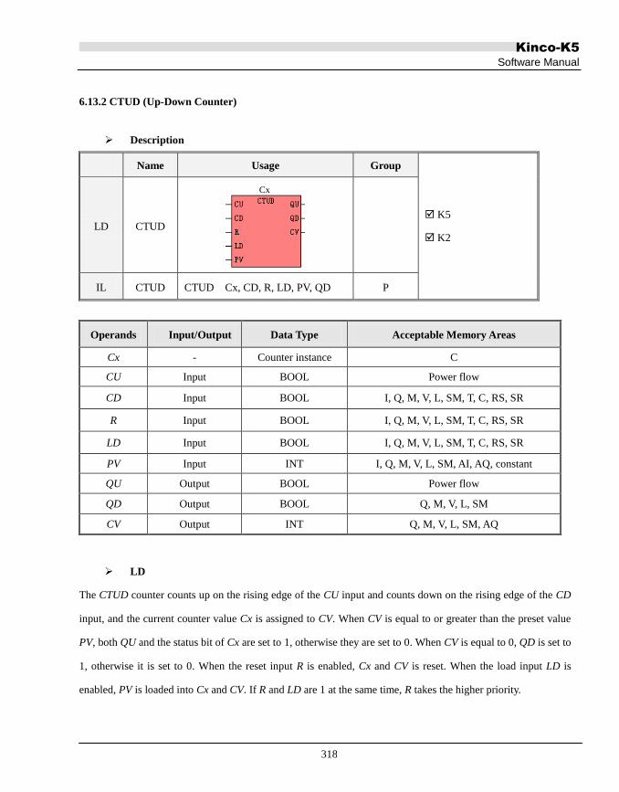
Kinco-K5
Software Manual
318
6.13.2 CTUD (Up-Down Counter)
Description
Name Usage Group
K5
K2 LD CTUD
Cx
IL CTUD CTUD Cx, CD, R, LD, PV, QD P
Operands Input/Output Data Type Acceptable Memory Areas
Cx - Counter instance C
CU Input BOOL Power flow
CD Input BOOL I, Q, M, V, L, SM, T, C, RS, SR
R Input BOOL I, Q, M, V, L, SM, T, C, RS, SR
LD Input BOOL I, Q, M, V, L, SM, T, C, RS, SR
PV Input INT I, Q, M, V, L, SM, AI, AQ, constant
QU Output BOOL Power flow
QD Output BOOL Q, M, V, L, SM
CV Output INT Q, M, V, L, SM, AQ
LD
The CTUD counter counts up on the rising edge of the CU input and counts down on the rising edge of the CD
input, and the current counter value Cx is assigned to CV. When CV is equal to or greater than the preset value
PV, both QU and the status bit of Cx are set to 1, otherwise they are set to 0. When CV is equal to 0, QD is set to
1, otherwise it is set to 0. When the reset input R is enabled, Cx and CV is reset. When the load input LD is
enabled, PV is loaded into Cx and CV. If R and LD are 1 at the same time, R takes the higher priority.

Kinco-K5
Software Manual
319
IL
The CTUD counter counts up on the rising edge of CR and counts down on the rising edge of the CD input, and
the current counter value Cx is assigned to CV. When CV is equal to or greater than the preset value PV, both
QU and the status bit of Cx are set to 1, otherwise they are set to 0. When CV is equal to 0, QD is set to 1,
otherwise it is set to 0. When the reset input R is enabled, Cx and CV is reset. When the load input LD is enabled,
PV is loaded into Cx and CV. If R and LD are 1 at the same time, R takes the higher priority.
After each scan, CR is set to be the status bit value of Cx.
Example
LD IL
LD %I0.0
CTUD C1, %I0.1, %I0.2, %I0.3, 4 ,%Q0.1
ST %Q0.0
Time Sequence Diagram
I0.0
Q0.0 and
The status bit of C0
VW0 and
The current value of C0
Q0.1
0 1 2 1 2 3 4 5 4 3 12 0 1 2
I0.1

Kinco-K5
Software Manual
320
6.13.3 High-speed Counter Instructions
High-speed counters count high-speed pulse inputs that cannot be controlled at the CPU scan rate.
Description
Name Usage Group
K5
K2
LD
HDEF
HSC
IL HDEF HDEF HSC, MODE
U HSC HSC N
The HDEF (High-speed Counter Definition) instruction is used to define the operation mode (MODE) of a
high-speed counter (HSC). This instruction is suitable for each high-speed counter. A high-speed counter can be
configured to be one of the 11 different operation modes. The mode decides the clock input, counting direction,
start, and reset properties of the high-speed counter.
The HSC (High-Speed Counter) instruction configures and operates the high-speed counter whose number is
specified by N according to the values of the corresponding SM registers.
Note: Call the HSC to start the high speed counter only once when you needs counting, if you use
Operands Input/Output Data Type Description
HSC Input INT Constant (HSC number)
MODE Input INT Constant (0~11, Operations mode)
N Input INT Constant (HSC number)

Kinco-K5
Software Manual
321
SM0.0 to call the HSC all the time , the high speed counter will be initialized all the time, so the high
speed counter cannot count the pulse probably.
In IL, CR decides whether to execute the HDEF and HSC instructions. They won‟t influence CR.
LD
If the EN value is 1 then execute HDEF and HSC and vice versa.
IL
If the CR value is 1 then execute HDEF and HSC and vice versa..
The execution of HDEF and HSC will not affect the CR value.
6.13.3.1 High-speed Counters Supported by the Kinco-K5
Feature CPU504, CPU504EX, CPU506, CPU506EA, CPU508
High-speed counters
Single phase
Two phase
2 counters (HSC0 and HSC1)
2 at 60KHz
2 at 20KHz.
Before started, the high-speed counter should be assigned an operation mode by HDEF command. All the
high-speed counters have the same function in the same operation mode.
Each input of a high-speed counter functions as follows:
6.13.3.2 Operation Modes and Inputs of the High-speed Counters
Input signals of high-speed counter include: clock (input impulse), direction, start and reset.
If the Start input is 0, then Clock input and Reset input will be ignored and current value remains
unchanged. If the Start input is 1 and Reset signal is 0, the counter is allowed to count. If the Reset input and
Start input are both 1, current value will be cleared. For single-phase high-speed counter controlled by Direction
input. If the Direction input is 1, then counter is incremented, otherwise, counter is decremented.

Kinco-K5
Software Manual
322
In different operation modes input signals is different. Please see below:
HSC 0
Mode Description I0.1 I0.0 I0.5
0 Single-phase up/down counter
with internal direction control: SM37.3 Clock
1 Reset
2 Reset Start
3 Single-phase up/down counter
with external direction control Clock
Direction
4 Reset Direction
6 Two-phase counter with up/down clock inputs Clock Down Clock Up
9 A/B phase quadrature counter Clock A Clock B
HSC 1
Mode Description I0.4 I0.6 I0.3 I0.2
0 Single-phase up/down counter
with internal direction control: SM47.3
Clock
1 Reset
2 Reset Start
3 Single-phase up/down counter
with external direction control
Clock
Direction
4 Reset Direction
5 Reset Start Direction
6 Two-phase counter
with up/down clock inputs
Clock Down Clock Up 7 Reset
8 Reset Start
9
A/B phase quadrature counter
Clock A Clock B 10 Reset
11 Reset Start

Kinco-K5
Software Manual
323
6.13.3.3 Time Sequence of High-speed Counter
In order to help you well understand the high-speed counter, the following diagrams shows various time
sequences.
Reset and Start
The operations in the following figures are suitable for all modes that use the reset and start inputs.
Reset Interrupt occurs
Current value is some value in this range
1
0
0
Reset
(Active High)
-2,147,483,648
2,147,483,647
Current Value
Figure 6-2 Time Sequence with Reset and without Start

Kinco-K5
Software Manual
324
Figure 6-3 Time Sequence with Reset and Start
1
0
1
0
0Current Value
Internal
Direction Control
(1=Up)
Clock
PV=CV interrupt occursDirection changed in the interrupt routine
Current value is 0, preset value is 4, counting direction is up.Enable bit is set to enabled.
1
2
1
2
3 3
4
-1
Figure 6-4 Time Sequence of Mode 0, 1 or 2

Kinco-K5
Software Manual
325
1
0
1
0
0
Current Value
External
Direction Control
(1=Up)
Clock
PV=CV interrupt occurs
Current value is 0, preset value is 4, counting direction is up.Enable bit is set to enabled.
1
2
1
2
3 3
4
5
PV=CV interrupt occursDirection changed interrupt occurs
Figure 6-5 Time Sequence of Mode 3, 4 or 5
1
0
1
0
0
Current Value
Clock Down
Clock Up
PV=CV interrupt occurs
Current value is 0, preset value is 4, initial counting direction is up.Enable bit is set to enabled.
1
2
1
2
3 3
4
5
PV=CV interrupt occursDirection changed interrupt occurs
4
Figure 6-6 Time Sequence of Mode 6, 7 or 8

Kinco-K5
Software Manual
326
1
0
1
0
0
Current Value
Clock B
Clock A
PV=CV interrupt occurs
Current value is 0, preset value is 3, initial counting direction is up.Enable bit is set to enabled.
1
2 2
3 3
4
PV=CV interrupt occursDirection changed interrupt occurs
Figure 6-7 Time Sequence of Mode 9, 10 or 11 (Quadrature, 1x rate)
6.13.3.4 Control Byte and Status Byte
Control Byte
In SM area each high-speed counter is assigned control byte to save its configuration data: one control word (8
bit), current value and pre-set (double-integer with 32 bit). Initial value of current assigned. If the current value is
written in the high-speed counter, it will start counting from that value. Please see below:
HSC0 HSC1 Description
SM37.0 SM47.0 Effective electrical level of reset signal:0=high;1=low
SM37.1 SM47.1 Effective electrical level to start signal:0=high;1=low
SM37.2 SM47.2 Orthogonal counter rate:0=1x rate;1=4x rate*
SM37.3 SM47.3 Counting direction 0=minus;1=plus
SM37.4 SM47.4 Write counting direction in HSC? 0= NO; 1= Yes
SM37.5 SM47.5 Write new pre-set value in HSC? 0= NO; 1= Yes
SM37.6 SM47.6 Write new current value in HSC? 0= NO; 1= Yes
SM37.7 SM47.7 Allow this high-speed counter? 0=NO; 1= YES
HSC0 HSC1 Description
SMD38 SMD48 Current value

Kinco-K5
Software Manual
327
SMD42 SMD52 Pre-set value
Please note that not all the control bits are suitable for all the operation modes. For example: “Counting
direction” and “Write the counting direction to the HSC” are only suitable for operation mode
0/1/2(Single-phase up/down counter with internal direction control). If operation modes of counter with
external direction control are chosen, then the two bits will be ignored.
The default values of control word, current value and preset value are 0.
Only after the high-speed counter and its mode are defined, can the dynamic parameters of the counter be
programed. A control byte is provided for each high-speed counter, and you can operate as follows:
Enable or disable the HSC
The counting direction control (limited to mode 0, 1 and 2), or the initial direction of all other modes
Load the current value
Load the preset value
The control byte, relevant current value and preset value shall be loaded before executing the HSC instruction.
The following table describes each of these control bits.
Status Byte
In SM area, each high-speed counter has a status byte, in which some bits indicate the current counting direction
and whether the current value is equal to or greater than the preset value. Definition of the status bits for each
high-speed counter is shown in the following table.
HSC0 HSC1 Description
SM36.0 SM46.0 Reserved
SM36.1 SM46.1 Reserved
SM36.2 SM46.2 Reserved
SM36.3 SM46.3 Reserved
SM36.4 SM46.4 Reserved
SM36.5 SM46.5 Current counting direction:
0 = Down; 1= Up

Kinco-K5
Software Manual
328
SM36.6 SM46.6 Current value equal to preset value:
0 = Not equal; 1 = Equal
SM36.7 SM46.7 Current value greater than preset value:
0 = Not greater than; 1 = Greater than
Accessing the Current Value of a High-Speed Counter
The current counting value of a high-speed counter is read-only and can be represented only as a double integer
(32-bit). The current counting value of a high-speed counter is accessed using the memory type (HC) and the
counter number; for example, HC0 represents the current value of HSC0, as shown in the following diagram.
LSB
0
MSB
31
byte 0 byte 1 byte 2 byte 3
Least significant Most significant
HC
Memory identifier (high-speed counter)
2
High-speed counter number
Figue 6-8 Accessing the Current Value of a High-Speed Counter
6.13.3.5 Assigning Interrupts
Each mode supports a PV=CV (the current value equal to the preset value) interrupt. The mode that use an
external reset input supports an External Reset interrupt. The mode that use an external direction control input
supports a Direction Changed interrupt. Each of these interrupt conditions can be enabled or disabled separately.
Please refer to 6.10 Types of Interrupt Events Supported by the Kinco-K5 for details.

Kinco-K5
Software Manual
329
6.13.3.6 Programming the High-speed Counter
You can program a high-speed count as follows:
Assign the control byte.
Assign the current value (i.e. starting value) and the preset value.
(Optional) Assign the interrupt routines using the ATCH instruction.
Define the counter and its mode using the HDEF instruction.
Note: The HDEF instruction can only be executed once for each high-speed counter after the CPU enters
RUN mode.
Start the high-speed counter using the HSC instruction.
The following is the detailed introduction for the initialization and operation steps taking HSC0 as an example.
You are recommended to make a subroutine that contains the HDEF instruction and other initialization
instructions and call this subroutine in the main program using SM0.1 to reduce the CPU cycle time.
Using HSC
The following example uses Mode 9. And the other modes take the similar steps.
In the initialization subroutine, load the desired control status into SMB37.
For example (1x counting rate), SMB37 = b#16#F0 indicates:
Enable HSC0
Write a new current value to HSC0
Write a new preset value to HSC0
Set the start input and the reset input to be active high
Load the desired current value (32-bit) into SMD38. If 0 is loaded, SMD38 is cleared.
Load the desired preset value (32-bit) into SMD42.
(Optional) Attach the CV = PV event (event 18) to an interrupt routine to respond in real time to a
current-value-equal-to-preset-value event.

Kinco-K5
Software Manual
330
(Optional) Attach the direction-changed event (event 17) to an interrupt routine to respond in real time to a
direction-changed event.
(Optional) Attach the external reset event (event 16) to an interrupt routine to respond in real time to an
external reset event
Execute the HDEF instruction with the HSC input set to be 0 and the MODE input set to 9.
Execute the HSC instruction to cause the CPU to configure HSC0 and start it.
Change the Counting Direction in Mode 0, 1 and 2:
The following introduces how to change the direction of HSC0 (Mode 0, 1 and 2).
Load the desired control status into SMB37:
SMB37 = b#16#90: Enable the counter,
Set the new direction to be down-counter
Execute the HSC instruction to cause the CPU to configure HSC0 and start it.
Load the new current value (in all the modes)
The following introduces how to change the current value (i.e. starting value) of HSC0.
Load the desired control status into SMB37:
SMB37 = b#16#C0 Enable the counter
Allow writing the new current value to HSC0.
Load the desired current value into SMD38. If 0 is loaded, SMD38 is cleared.
Execute the HSC instruction to cause the CPU to configure HSC0 and start it.
Load the new preset value (in all the modes)
The following introduces how to change the preset value of HSC0.
Load the desired control status into SMB37:
SMB37 = b#16#A0 Enable the counter

Kinco-K5
Software Manual
331
Allow writing the new preset value to HSC0.
Load the desired preset value into SMD42.
Execute the HSC instruction to cause the CPU to configure HSC0 and start it.
Disable the High-speed Counter (in all modes)
The following introduces how to disable HSC0.
Load the desired control status into SMB37:
SMB37 = b#16#00 Disable the counter;
Execute the HSC instruction to cause the CPU to disable the counter.
6.13.3.7 Examples
The following example also uses HSC0.

Kinco-K5
Software Manual
332
LD
The initialization subroutine: Initialize

Kinco-K5
Software Manual
333
LD
The interrupt routine: ReachPV
Main program:

Kinco-K5
Software Manual
334
IL
The initialization subroutine: Initialize
(* Network 0 *)
(* 1x counting rate; Enable HSC0; Allow updating current value AND preset value; *)
(* Set the start input and the reset input to be active high *)
LD %SM0.0
MOVE B#16#E0, %SMB37
(* Network 1 *)
(*Set the new current value and new preset value*)
LD %SM0.0
MOVE DI#0, %SMD38
MOVE DI#100, %SMD42
(* Network 2 *)
(*Attach the CV = PV event (event 18) to ReachPV interrupt routine*)
LD %SM0.0
ATCH ReachPV, 18
(* Network 3 *)
(*Define HSC0 to be in mode 9*)
LD %SM0.0
HDEF 0, 9
(* Network 4 *)
(*Configure and start HSC0*)
LD %SM0.0
HSC 0

Kinco-K5
Software Manual
335
IL
The interrupt routine: ReachPV
(* Network 0 *)
(*Allow updating current value*)
LD %SM0.0
MOVE B#16#C0, %SMB37
(* Network 1 *)
(*Set the new current value to be 0 to re-count*)
LD %SM0.0
MOVE DI#0, %SMD38
(* Network 2 *)
(*Configure and restart HSC0*)
LD %SM0.0
HSC 0
Main program:
(* Network 0 *)
(*Call Initialize subroutine*)
LD %SM0.1
CAL Intialize

Kinco-K5
Software Manual
336
6.13.4 Pulse-Width Modulation (PWM)
Here the high-speed pulse output means the Pulse-Width Modulation (PWM).
K5 provides two PWM impulse generator to output PWM, using tunnel of Q0.0 and Q0.1, called PWM0 and
PWM1. The generator and DO image register share the same address Q0.0 and Q0.1. If PWM is started in Q0.0
or Q0.1, the generator will control the output tunnel and forbid the output of general function.When PWM
function is forbidden, Q0.0 and Q0.1 will be controlled by DO image register.
The highest output rate of CPU modules is 200kHz.
Description
Name Usage Group
K5
K2 LD PLS
IL PLS PLS Q U
Operands Input/Output Data Type Description
Q Input INT Constant (0 or 1)
The PLS instruction is used to load the corresponding configurations of the PTO/PWM specified by Q from the
specified SM registers and then operate the PTO/PWM generator accordingly.
In LD, the EN input decides whether to execute the PLS instruction.
In IL, CR value decides whether to execute the PLS instructions. It won‟t influence CR.
Note: If Q0.0/Q0.1 is relay type, please do not use high speed pulse output function.

Kinco-K5
Software Manual
337
6.13.4.1 Configuring and Controlling the PWM Operation
Each PWM generator is provided with some registers in SM area to store its configurations or indicate its status.
The characteristics of a PWM waveform can be changed by modifying the corresponding SM registers and then
executing the PLS instruction. The following table decribes control registers detaildly.
Q0.0 Q0.1 Description
SM67.0 SM77.0 Whether to update the cycle time:
0 = not update; 1 = update
SM67.1 SM77.1 Whether to update pulse width time:
0 = not update; 1 = update
SM67.2 SM77.2 Reserve
SM67.3 SM77.3 Time base:0 = 1μs; 1 = 1ms
SM67.4 SM77.4 Reserve
SM67.5 SM77.5 Reserve
SM67.6 SM77.6 1 = PWM
SM67.7 SM77.7 Enable: 0 = disable; 1 = enable
SMW68 SMW78 Cycle time value, Range: 2 to 65535
SMW70 SMW80 Pulse width value, Range: 0 to 65535
6.13.4.2 PWM Operations
The fallowing takes PWM0 as an example to introduce how to configure and operate the PWM generator in the
user program.
Initializing the PWM Output
Use SM0.1 (the first scan memory bit) to call a subroutine that contains the initialization instructions. Since
SM0.1 is used, the subroutine shall be invoked only once, and this reduces scan time and provides a better
program structure.

Kinco-K5
Software Manual
338
The following steps describes how to configure PWM0 in the initialization subroutine:
Load the desired control status into SMB67:
For example, SMB67 = B#16#D3 indicates
Enable the PWM function
Select PWM operation
Select 1μs as the time base
Allow updating the pulse width value and cycle time value
Setlect synchronousv update method
Load the cycle time value into SMW68.
Load the pulse width value into SMW70.
Execute the PLS struction to cause the CPU to configure PWM0 and start it.
Changing the Pulse Width for the PWM Output
The following steps describes how to change PWM output pulse width (assume that SMB67 has been preloaded
with B#16#D2 or B#16#DA.):
Load the desired control status into SMB67
For example, SMB67 = B#16#D2 indicates
Enable the PWM function
Select PWM operation
Select 1μs as the time base
Allow updating the pulse width value
Setlect synchronousv update method
Load the pulse width value (16-bit) into SMW70.
Execute the PLS struction to cause the CPU to configure PWM and start it.

Kinco-K5
Software Manual
339
6.13.4.3 Example
PWM
PWM1 (output through Q0.1) is used in the example.
If I0.0 is false, change the pulth width to 40% duty cycle; if I0.0 is true, change the pulth width to 40%
duty cycle. The time sequence diagram is shown as follows:
I0.0
Q0.0
LD
MAIN Program:

Kinco-K5
Software Manual
340
LD
Subroutine InitPWM1:

Kinco-K5
Software Manual
341
LD
Subroutine PWM1:

Kinco-K5
Software Manual
342
IL
MAIN Program:
(* Network 0 *)
(* Use SM0.1 to call subroutine InitPWM1 to initialize PWM1 *)
LD %SM0.1
CAL InitPWM1
(* Network 1 *)
(* If the status of I0.0 changes, subroutine PWM1 shall be called to change the pulse width. *)
LD %I0.0
ANDN %M0.0
OR(
LDN %I0.0
AND %M0.0
)
CAL PWM1
(* Network 2 *)
LD %I0.0
ST %M0.0

Kinco-K5
Software Manual
343
IL
Subroutin InitPWM1:
(* Network 0 *)
(*Select PWM1; Select 1ms as the time base; Allow updating the cycle time value and the pulth width*)
LD %SM0.0
MOVE B#16#CF, %SMB77
(* Network 1 *)
(*Set the cycle time of PWM1 to be 10ms*)
LD %SM0.0
MOVE 10, %SMW78
(* Network 2 *)
(*Set the pulse width of PWM1 to be 4ms*)
LD %SM0.0
MOVE 4, %SMW80
(* Network 3 *)
(*Execute PWM1*)
LD %SM0.0
PLS 1
Subroutin PWM1:
(* Network 0 *)
(*If I0.0 is false, the pulse width of PWM1 is set to be 4ms*)
LDN %I0.0
MOVE 4, %SMW80
(* Network 1 *)
(*If I0.0 is true, the pulse width of PWM1 is set to be 8ms*)
LD %I0.0
MOVE 8, %SMW80
(* Network 2 *)
(*Execute PWM1*)
LD %SM0.0
PLS 1

Kinco-K5
Software Manual
344
6.14 Timers
Timer is one of the function blocks defined in the IEC61131-3 standard, totally in three types i.e. TON, TOF
and TP. Please refer to 2.6.5 Function Block and Function Block Instance for more detailed information.
6.14.1 The resolution of the timer
There are three resolutions for timers in K5. The timer number determines the resolution.
The resolution of the time numbers T0-T3 is 1ms; the resolution of the time numbers T4-T19 is 10ms; the
resolution of the time numbers T20-T255 is 100ms
The maxim value of the timer is 32767× Resolution. The preset value and the current value of a timer are all
multiples of this timer‟s resolution, for example, a value of 100 on a 10ms timer represents 1000ms.
PLC will update the timing value of the timer only when execute the timer command. It will be
influenced by the scan cycle.
6.14.2 TON (On-delay Timer)
Description
Name Usage Group
K5
K2 LD TON
IL TON TON Tx, PT P
Operands Input/Output Data Type Acceptable Memory Areas
Tx - Timer instance T

Kinco-K5
Software Manual
345
IN Input BOOL Power flow
PT Input INT I, AI, AQ, M, V, L, SM, constant
Q Output BOOL Power flow
ET Output INT Q, M, V, L, SM, AQ
This timer is affected by the plc scanning time, if user needs more accuracy timing. Please user the
timed interrupt 1 and 2, which event number are 3 and 4.
Tx is an instance of TON fuction block.
LD
Tx starts to time on the rising edge of the IN input. When the elapsed time (i.e. the current value) ET is greater
than or equal to the preset time PT, both the Q output and the status bit of Tx are set to be TRUE. If the IN input
turns to FALSE, Tx is reset, and both the Q output and its status bit value are set to be FALSE, meanwhile its
current value is cleared to 0.
IL
Tx starts to time on the rising edge of CR. When the current value is greater than or equal to the preset value PT,
the status bit of Tx is set to be TRUE. If CR turns to FALSE, Tx is reset, and its status bit is set to be FALSE,
meanwhile its current value is cleared to 0. After each scan, CR is set to be the status bit value of Tx.

Kinco-K5
Software Manual
346
Examples
LD IL
(* NETWORK 0 *)
LD %I0.0
TON T5, 100
ST %M0.0
Time Sequence Diagram
I0.0
VW10
T5 (current)
M0.0
T5 (bit)
PTETPT

Kinco-K5
Software Manual
347
6.14.3 TOF (Off-delay Timer)
Description
Name Usage Group
K5
K2 LD TOF
IL TOF TOF Tx, PT P
Operands Input/Output Data Type Acceptable Memory Areas
Tx - Timer instance T
IN Input BOOL Power flow
PT Input INT I, AI, AQ, M, V, L, SM, constant
Q Output BOOL Power flow
ET Output INT Q, M, V, L, SM, AQ
This timer is affected by the plc scanning time, if user needs more accuracy timing. Please user the
timed interrupt 1 and 2, which event number are 3 and 4.
Tx is an instance of TOF fuction block.
LD
Tx starts to time on the falling edge of the IN input. When the elapsed time (i.e. the current value) ET is greater
than or equal to the preset time PT, both the Q output and the status bit of Tx are set to be FALSE. If the IN
input turns to TRUE, Tx is reset, and both the Q output and it status bit are set to be TRUE, meanwhile its

Kinco-K5
Software Manual
348
current value is cleared to 0.
IL
Tx starts to time on the falling edge of CR. When the current value is greater than or equal to the preset value
PT, the status bit of Tx is set to be FALSE. If CR turns to TRUE, Tx is reset, and its status bit is set to be TRUE,
meanwhile its current value is cleared to 0. After each scan, CR is set to be the status bit value of Tx.
Examples
LD IL
(* NETWORK 0 *)
LD %I0.0
TOF T5, 100
ST %M0.0
Time Sequence Diagram

Kinco-K5
Software Manual
349
I0.0
VW0
T5 (current)
M0.0
T5 (bit)
PT ETPT

Kinco-K5
Software Manual
350
6.14.4 TP (Pulse Timer)
Description
Name Usage Group
K5
K2 LD TP
IL TP TP Tx, PT P
Operands Input/Output Data Type Acceptable Memory Areas
Tx - Timer instance T
IN Input BOOL Power flow
PT Input INT I, AI, AQ, M, V, L, SM, constant
Q Output BOOL Power flow
ET Output INT Q, M, V, L, SM, AQ
This timer is affected by the plc scanning time, if user needs more accuracy timing. Please user the
timed interrupt 1 and 2, which event number are 3 and 4.
Tx is an instance of TP fuction block. The TP instruction is used to generate a pulse for the preset time.
LD
On the rising edge of the IN input, Tx starts to time, and both the Q output and the status bit of Tx are set to be
TRUE. The Q output and the status bit remain TRUE within the preset time PT. As soon as the elapsed time (i.e.
the current value) ET reaches the PT, both the Q output and the status bit become FALSE.
IL
On the rising edge of CR, Tx starts to time, and the status bit of Tx is set to be TRUE. The status bit remains

Kinco-K5
Software Manual
351
TRUE within the preset time PT. As soon as the current value reaches the PT, the status bit becomes FALSE.
After each scan, CR is set to be the status bit value of Tx.
Examples
LD IL
(* NETWORK 0 *)
LD %I0.0
TP T5, 100
ST %M0.0
Time Sequence Diagram
I0.0
VW0
T5 (current)
M0.0
T5 (bit)
ETPT PT PT

Kinco-K5
Software Manual
352
6.15 PID
A PID controller is used to correct the error between the measured process variable and the desired set-point by
calculating and then outputting a corrective action that can adjust the process accordingly.
Kinco-K5 provides PID instruction to serve as a digital PID loop controller. You can use it for PID fixed
set-point control with continuous input and output, and you can use up to 8 PID loops in one CPU.
6.15.1 PID
Description
Name Usage Group
K5
K2
LD PID
IL PID
PID AUTO, PV, SP, XO, KP, TR, TD,
PV_H, PV_L, XOUTP_H, XOUTP_L,
CYCLE, XOUT, XOUTP
U

Kinco-K5
Software Manual
353
This instruction adopts position algorithm, and its input and output are continuous.
LD
If EN is 1, this instruction is executed. PLC samples value of PV, calculates and outputs result at intervals of
sampling period (CYCLE).
IL
If EN is 1, this instruction is executed, and it does not influence CR. PLC samples value of PV, calculates
and outputs result at intervals of sampling period (CYCLE).
Detailed descriptions for PID instruction
Operands IN/OUT Data Type Memory Areas Comment
AUTO INPUT BOOL I, Q, V, M, SM,
L, T, C
Manual/Auto.
0=Manual, 1=Auto.
PV INPUT INT AI, V, M, L Process Variable
SP INPUT INT V Set-point
XO INPUT REAL V Manual value, range [0.0, 1.0]
KP INPUT REAL V Proportionality constant
TR INPUT REAL V Reset time, which determines the time
response of the integrator. (Unit: s)
TD INPUT REAL V Derivative time, which determines the time
response of the derivative unit. (Unit: s)
PV_H INPUT INT V The upper limit value of PV
PV_L INPUT INT V The lower limit value of PV
XOUTP_H INPUT INT V The upper limit value of XOUTP
XOUTP_L INPUT INT V The lower limit value of XOUTP
CYCLE INPUT DINT V Sampling period. (Unit: ms)
XOUT OUTPUT REAL: V Manipulated Value, range [0.0, 1.0].
XOUTP OUTPUT INT AQ, V Manipulated Value Peripheral.
This value is the normalizing result of XOUT.

Kinco-K5
Software Manual
354
Manual/Auto
It is possible to switch between a manual and an automatic mode with the help of Auto input.
If Auto is 0, then the PID is in the manual mode, and now the value of XO input shall be directly set as the
manipulated value (XOUT).
If Auto is 1, then the PID is in the automatic mode, and now it shall execute the PID calculations according to
the inputs and set the final result as the manipulated value (XOUT).
A PID controller should be in the automatic mode while it is performing a process control.
Normalizing the PV and SP
The PV and SP can be input in the peripheral format (an integer). But PID algorithm needs a floating-point
value of 0.0 to 1.0, so normalization is needed.
The Kinco-K5 automatically finishes the normalization according to the PV, SP, PV_H and PV_L input. You
may assign any linear correlation values of them, but the inputs must be the same dimension.
For example, you want to control the pressure to the expected value 25MPa. A pressure transmitter is used to
measure the pressure, and the transformer‟s measuring range is 0-40MPa and its output range is 4-20mA. The
transformer‟s output is connected to a channel of an AI module, and this channel is configured as the following:
the address is AIW0, and the measured type is „4-20mA‟ whose the measured value is „4000-20000‟. Now, you
can assign the following values to the PID inputs:
Actual Parameter Comment
PV AIW0 AIW0 can be set as PV because of their linear relation.
SP 14000 14mA. Because 14mA means the real pressure value 25MPa.
PV_L 4000 The lower limit value of the transformer‟s output
PV_H 20000 The upper limit value of the transformer‟s output
Manipulated Values
This PID has two manipulated values: XOUT and XOUTP.
XOUT is a value between 0.0 and 1.0 (that is between 0.0 and 100.0%).
XOUTP is an integer value with the user-defined peripheral format, and it is the result of normalizing XOUT

Kinco-K5
Software Manual
355
according to the XOUTP_H and XOUTP_L input:
XOUTP = (XOUTP_H - XOUTP_L )* XOUT + XOUTP_L
It is convenient for the user to transfer XOUT_P to an AO channel. For example, PID results should be sent
to a regulating valve via AQW0 of AO module, then the related parameter settings are as follows:
Actual Parameter Comment
XOUTP AQW0 AQW0 could be directly taken as PID output for the linear
relationship between value of AQW0 and opening of valve.
XOUTP_L 4000 The lower limit value of the AQW0.
XOUTP_H 20000 The upper limit value of the AQW0.
PID Diagram
PV
PV_H,PV_L
Normalization
PV_H,PV_L
SP
×+-
KP
TR
Integrator
TD
Differential
XO ..
AUTO
0
1
XOUT
XOUTP_H,XOUTP_L
Normalization
XOUTP
Normalization
Example
In this example, we build a control system, and the system will maintain a constant temperature
inside a box.

Kinco-K5
Software Manual
356
IL
(* Network 0 *)
(* At first, enter the actual parameters *)
LD %SM0.0
MOVE 7200, %VW0 (* SP *)
MOVE 4000, %VW2 (* PV_L *)
MOVE 20000, %VW4 (* PV_H *)
MOVE 4000, %VW6 (* XOUTP_L *)
MOVE 20000, %VW8 (* XOUTP_H *)
(* Network 1 *)
(* Execute PID *)
LD %SM0.0
PID %M0.0, %AIW0, %VW0, %VR100, %VR104, %VR108, %VR112, %VW4, %VW2, %VW8,
%VW6, %VD10, %VR116, %AQW0

Kinco-K5
Software Manual
357
6.16 Position Control
The Kinco-K5 provides 2 high-speed pulse output channels: Q0.0 and Q0.1, and can be used for position
control for 2 axes. In 6.13.4 Pulse Width Modulation (PWM), the usage of PWM and the PLS instruction is
described detailedly.
The Position Control instructions described in this chapter is another usage of the high-speed pulse output
function. Comparing with the PLS instruction, the Position Control instructions are more convenient for the
position control applications. Similarly, the frequency of the pulse output is between 20kHz-200kHz.
6.16.1 Model
The following diagram is focused on a single axis, and it normatively defines the behavior of the axis at a high
level when the position control instructions are activated. The basic rule is that position commands are always
taken sequentially.
The axis is always in one of the defined state (see diagram below). Any position command is a transition that
changes the state of the axis and, as a consequence, modifies the way the current position is computed.
Discrete Motion
Stopped
Homing
Standstill
PSTOP
Finished/ErrorPHOME
Finished/Erro
r
PABS
PREL
PJOG
PSTOP
Reset th
e
Em
ergen
cy-sto
p
flag(1
)
PS
TO
P
The Emergency-Stop flag is SM201.7/ SM231.7. It will be set to 1 automatically while executing the
PSTOP instruction. Please refer to the detailed description in the following section.

Kinco-K5
Software Manual
358
6.16.2 The correlative variables
6.16.2.1 The direction output channel
For the Position Control instructions, the Kinco-K5 specifies a direction output channel for each high-speed
pulse output channel, and a control bit in the SM area to enable the direction output. Please see the following
table.
High-speed Pulse Output Channel Q0.0 Q0.1
Direction output channel Q0.2 Q0.3
Direction control bit SM201.3 SM231.3
The direction output channel is used for providing a direction signal which controls the direction of the electric
motors: 0 means rotating forwards, and 1 means rotating backwards.
The direction control bit is used to disable or enable the corresponding direction output channel. The direction
control bit has the highest priority. If disabled, no direction signal will be provided while executing a position
control instruction and the corresponding direction output channel can be used as a normal DO point.
6.16.2.2 The Status and Control Registers
For the Position Control instructions, the Kinco-K5 specifies a control byte for each high-speed output channel
to store its configurations.
A status register is also specified for storing the current value (the number of pulses output, DINT). The current
value increases when rotating forwards, and decreases when rotating backwards. The following table describes
these registers detailedly. Note: After a position control instruction has finished, the current value will not be
cleared automatically, and you can clear it in your program.
The following table describes the control byte and the current value.
Q0.0 Q0.1 Description
SM201.7 SM231.7 Emergency-Stop flag.

Kinco-K5
Software Manual
359
If this bit is 1, no position control instructions can be executed.
When executing the PSTOP instruction, this bit is set to 1
automatically, and it must be reset by your program.
SM201.6 SM231.6
Reset the current value or not
1 --- Clear the current value.
0 --- Maintain the current value.
SM201.5~SM201.4 SM231.4~SM231.5 Reserved
SM201.3 SM231.3
Direction control bit.
1 --- Disable the direction output channel.
0 --- Enable the direction output channel.
SM201.0~SM201.2 SM231.0~SM231.2 Reserved
Q0.0 Q0.1 Description
SMD212 SMD242 The current value
6.16.2.3 The error identification
During the execution of the position control instructions, non-fatal errors may occur, then the CPU will generate
error identification, and write it to the ERRID parameter of the instruction. The following table describes these
error codes and their descriptions.
Error Code Description
0 No error
1 Acceleration/deceleration time is too short or the initial speed is too low, leading to
initial pulse period exceed preset TIME for each segment.
2 The value of MINF is larger than the value of MAXF(200KHz).
3 The value of MINF is less than the allowed lowest frequency (125Hz).
4 Pulses numbers required for acceleration and deceleration exceed total pulse numbers
5 The value of MINF is larger than that of MAXF

Kinco-K5
Software Manual
360
6.16.3 PHOME (Homing)
Description
Name Usage Group
K5
K2
LD PHOME
IL PHOME
PHOME AXIS, EXEC, HOME, NHOME, MODE,
DIRC, MINF, MAXF, TIME, DONE, ERR,
ERRID
U
Operands Input/Output Data Type Acceptable Memory Areas
AXIS Input INT Constant (0 or 1)
EXEC Input BOOL I, Q, V, M, L, SM, RS, SR
HOME Input BOOL I, Q, V, M, L, SM, RS, SR
NHOME Input BOOL I, Q, V, M, L, SM, RS, SR
MODE Input INT I, Q, V, M, L, SM, T, C, AI, AQ, Constant
DIRC Input INT I, Q, V, M, L, SM, T, C, AI, AQ, Constant
MINF Input WORD I, Q, M, V, L, SM, Constant
MAXF Input DWORD I, Q, M, V, L, SM, Constant
TIME Input WORD I, Q, M, V, L, SM, Constant
DONE Output BOOL Q, M, V, L, SM
ERR Output BOOL Q, M, V, L, SM
ERRID Output BYTE Q, M, V, L, SM
Note: MODE, DIRC, MINF, MAXF, TIME should be constants or variables simultaneously.

Kinco-K5
Software Manual
361
The SMD212 and SMD242 can only be reset (cleared) by SM201.6 and SM231.6. When
you use K5 to replace K3, please be aware of this, because the SMD212 and MD242 can be
reset (cleared) directly in K3 PLC.
The following table describes all the operands detailedly.
Operands Description
AXIS The high-speed output channel, 0 means Q0.0, 1 means Q0.1.
EXEC If EN is 1, the EXEC starts the „search home‟ motion on the rising edge.
HOME The home signal from the home sensor
NHOME The near home signal from the near home sensor
MODE
Specifies the homing mode:
0 means that the home signal and the near home signal are all used;
1 means that only the home signal is used.
DIRC
Specifies the rotating direction of the electric motor:
0 means rotating forwards; 1 means rotating backwards.
Please refer to 6.16.2.1 The direction output channel for more information.
MINF Specifies the initial speed (i.e., the initial frequency) of the pulse train output. Unit: Hz.
Note: the value of MINF must be equal to or less than 125Hz.
MAXF
Specifies the highest speed (i.e., the highest frequency) of the pulse train output. Unit: Hz.
The available range of MAXF is 125Hz ~ 200KHz.
MAXF must be larger than or equal to MINF.
TIME
Specifies the acceleration/deceleration time. Unit: ms.
In the position control instructions, the acceleration time is the same as the deceleration time.
The acceleration time is the time for the speed accelerating from MINF to MAXF.
The deceleration time is the time for the speed decelerating from MAXF to MINF.
DONE Indicates that the instruction has finished successfully.
0 = not finished; 1 = finished.
ERR Indicates that error has occurred during the execution.
0 = no error; 1 = an error has occurred.
ERRID Error identification.

Kinco-K5
Software Manual
362
This instruction controls the AXIS to execute the „search home‟ sequence using the HOME and NHOME signals.
The MODE specifies the homing mode. While executing the „search home‟ motion, if the DIRC is set to be 0
(rotating forwards), the current value (SMD212/SMD242) increases; if the DIRC is set to be 1 (rotating
backwards), the current value (SMD212/SMD242) decreases.
If the MODE is 0 (using both the HOME and the NHOME signals), the PHOME instruction will control
the AXIS to decelerate as soon as the NHOME becomes 1, and to stop as soon as the HOME becomes 1.
The timing diagram is as followings:
MAXF
MINF
NHOME
HOME
Start the
motionTIME TIME
Frequency(Hz)
Time(ms)
If the MODE is 1 (using the HOME signal only), the PHOME instruction will control the AXIS to stop as
soon as the HOME becomes 1. The timing diagram is as followings:
MAXF
MINF
HOME
Start the
motionTIME
Frequency(Hz)
Time(ms)
Notice: when the HOME signal becomes 1, the registers (SMD212/SM242) do not clear the current values; they
need change the current values in condition.

Kinco-K5
Software Manual
363
The SMD212 and SMD242 can only be reset (cleared) by SM201.6 and SM231.6. When
you use K5 to replace K3, please be aware of this, because the SMD212 and MD242 can be
reset (cleared) directly in K3 PLC.
LD
If EN is 1, this instruction is executed.
IL
If CR is 1, this instruction is executed, and it does not influence CR.

Kinco-K5
Software Manual
364
6.16.4 PABS (Moving Absolutely)
Description
Name Usage Group
K5
K2
LD PABS
IL PABS PABS AXIS, EXEC, MINF, MAXF, TIME, POS,
DONE, ERR, ERRID U
Operands Input/Output Data Type Acceptable Memory Areas
AXIS Input INT Constant (0 or 1)
EXEC Input BOOL I, Q, V, M, L, SM, RS, SR
MINF Input WORD I, Q, M, V, L, SM, Constant
MAXF Input DWORD I, Q, M, V, L, SM, Constant
TIME Input WORD I, Q, M, V, L, SM, Constant
POS Input DINT I, Q, M, V, L, SM, HC, Constant
DONE Output BOOL Q, M, V, L, SM
ERR Output BOOL Q, M, V, L, SM
ERRID Output BYTE Q, M, V, L, SM
Note: MINF, MAXF, TIME, POS should be constants or variables simultaneously.
The following table describes all the operands detailedly.
Operands Description
AXIS The high-speed output channel, 0 means Q0.0, 1 means Q0.1.
EXEC If EN is 1, the EXEC starts the absolute motion on the rising edge.

Kinco-K5
Software Manual
365
MINF Specifies the initial speed (i.e., the initial frequency) of the pulse train output. Unit: Hz.
Note: the value of MINF must be equal to or less than 125Hz.
MAXF
Specifies the highest speed (i.e., the highest frequency) of the pulse train output. Unit: Hz.
The available range of MAXF is 125Hz ~ 200KHz.
MAXF must be larger than or equal to MINF.
TIME
Specifies the acceleration/deceleration time. Unit: ms.
In the position control instructions, the acceleration time is the same as the deceleration time.
The acceleration time is the time for the speed accelerating from MINF to MAXF.
The deceleration time is the time for the speed decelerating from MAXF to MINF.
POS
Specifies the target value. It is represented with the number of pulses between the home
positon, where the current value is 0, and the target position.
As shown in the following figure, if the object is moved from A to B, the POS should be set as
'100'; If it is moved from B to C, the POS should be set as '300'; If it is moved from C to B, the
POS should be set as '100'.
? ? ?
A B C
Home (where the current value is 0 ) 100 300
DONE Indicates that the instruction has finished successfully.
0 = not finished; 1 = finished.
ERR Indicates that error has occurred during the execution.
0 = no error; 1 = an error has occurred.
ERRID Error identification.
If the Direction Control Bit (SM201.3/SM231.3) is set to 0, the PABS instruction will generate the direction
output signal at the corresponding direction output channel (Q0.2/Q0.3): If the target value is greater than the
current value, it generates a direction output of rotating forwards, then the current value (SMD212/SMD242)
increases; If the target value is less than the current value, it generates a direction output of rotating backwards,
and then the current value (SMD212/SMD242) decreases.

Kinco-K5
Software Manual
366
The timing diagram is as following:
MAXF
MINF
Start the
motionTIME TIME
Frequency(Hz)
Time(ms)
The number of the pulses
( the difference between the current value and POS )
LD
If EN is 1, this instruction is executed.
IL
If CR is 1, this instruction is executed, and it does not influence CR.

Kinco-K5
Software Manual
367
6.16.5 PREL (Moving Relatively)
Description
Name Usage Group
K5
K2
LD PREL
IL PREL PREL AXIS, EXEC, MINF, MAXF, TIME, DIST,
DONE, ERR, ERRID U
Operands Input/Output Data Type Acceptable Memory Areas
AXIS Input INT Constant (0 or 1)
EXEC Input BOOL I, Q, V, M, L, SM, RS, SR
MINF Input WORD I, Q, M, V, L, SM, Constant
MAXF Input DWORD I, Q, M, V, L, SM, Constant
TIME Input WORD I, Q, M, V, L, SM, Constant
DIST Input DINT I, Q, M, V, L, SM, HC, Constant
DONE Output BOOL Q, M, V, L, SM
ERR Output BOOL Q, M, V, L, SM
ERRID Output BYTE Q, M, V, L, SM
Note: MINF, MAXF, TIME, DIST should be constants or variables simultaneously.
The following table describes all the operands detailedly.
Operands Description
AXIS The high-speed output channel, 0 means Q0.0, 1 means Q0.1.
EXEC If EN is 1, the EXEC starts the relative motion on the rising edge.
MINF Specifies the initial speed (i.e., the initial frequency) of the pulse train output. Unit: Hz.

Kinco-K5
Software Manual
368
Note: the value of MINF must be equal to or less than 125Hz.
MAXF
Specifies the highest speed (i.e., the highest frequency) of the pulse train output. Unit: Hz.
The available range of MAXF is 125Hz ~ 200KHz.
MAXF must be larger than or equal to MINF.
TIME
Specifies the acceleration/deceleration time. Unit: ms.
In the position control instructions, the acceleration time is the same as the deceleration time.
The acceleration time is the time for the speed accelerating from MINF to MAXF.
The deceleration time is the time for the speed decelerating from MAXF to MINF.
DIST
Specifies the target distance. It is represented with the number of pulses between the current
position and the target position.
As shown in the following figure, if the object is moved from A to B, the DIST should be set as
'100'; If it is moved from B to C, the DIST should be set as '200'; If it is moved from C to B, the
DIST should be set as '-200'.
? ? ?
A B C
Home (where the current value is 0 ) 100 300
DONE Indicates that the instruction has finished successfully.
0 = not finished; 1 = finished.
ERR Indicates that error has occurred during the execution.
0 = no error; 1 = an error has occurred.
ERRID Error identification.
This instruction controls the AXIS to execute a motion of a specified distance (DIST) relative to the current value
at the time of the execution.
If the Direction Control Bit (SM201.3/SM231.3) is set to 0, the PREL instruction will generate the direction
output signal at the corresponding direction output channel (Q0.2/Q0.3): If the DIST is positive, it generates a
direction output of rotating forwards, then the current value (SMD212/SMD242) increases; If the DIST is
negative, it generates a direction output of rotating backwards, and then the current value (SMD212/SMD242)

Kinco-K5
Software Manual
369
decreases.
The timing diagram is as following:
MAXF
MINF
Start the
motionTIME TIME
Frequency(Hz)
Time(ms)
The number of the pulses:DIST
LD
If EN is 1, this instruction is executed.
IL
If CR is 1, this instruction is executed, and it does not influence CR.

Kinco-K5
Software Manual
370
6.16.6 PJOG (Jog)
Description
Name Usage Group
K5
K2
LD PJOG
IL PJOG PJOG AXIS, EXEC, MINF, DIRC,
DONE, ERR, ERRID U
Operands Input/Output Data Type Acceptable Memory Areas
AXIS Input INT Constant (0 or 1)
EXEC Input BOOL I, Q, V, M, L, SM, RS, SR
MAXF Input DWORD I, Q, M, V, L, SM, Constant
DIRC Input INT I, Q, M, V, L, SM, AI, AQ, T, C, Constant
DONE Output BOOL Q, M, V, L, SM
ERR Output BOOL Q, M, V, L, SM
ERRID Output BYTE Q, M, V, L, SM
Note: MAXF, DIRC should be constants or variables simultaneously.
The following table describes all the operands detailedly.
Operands Description
AXIS The high-speed output channel, 0 means Q0.0, 1 means Q0.1.
EXEC If EN is 1, the EXEC starts the jog motion on the rising edge.
MAXF Specifies the speed of the pulse train output. Unit: Hz.
DIRC Specifies the direction of the electric motors: 0 means rotating forwards, and 1 means rotating
backwards.
DONE Indicates that the instruction has finished successfully.

Kinco-K5
Software Manual
371
0 = not finished; 1 = finished.
ERR Indicates that error has occurred during the execution.
0 = no error; 1 = an error has occurred.
ERRID Error identification.
This instruction controls the AXIS to execute a jog motion: generating a durative pulse train output, whose
frequency is MAXF.
If the Direction Control Bit (SM201.3/SM231.3) is set to 0, the PJOG instruction will generate the direction
output signal at the corresponding direction output channel (Q0.2/Q0.3): if the DIRC is 0 (rotating forwards),
the current value (SMD212/SMD242) increases; if the DIRC is 1 (rotating backwards), the current value
(SMD212/SMD242) decreases.
LD
If EN is 1, this instruction is executed.
IL
If CR is 1, this instruction is executed, and it does not influence CR.

Kinco-K5
Software Manual
372
6.16.7 PSTOP (Stop)
Description
Name Usage Group
K5
K2 LD PSTOP
IL PSTOP PSTOP AXIS, EXEC, ERR, ERRID U
Operands Input/Output Data Type Acceptable Memory Areas
AXIS Input INT Constant (0 or 1)
EXEC Input BOOL I, Q, V, M, L, SM, RS, SR
ERR Output BOOL Q, M, V, L, SM
ERRID Output BYTE Q, M, V, L, SM
The following table describes all the operands detailedly.
Operands Description
AXIS The high-speed output channel, 0 means Q0.0, 1 means Q0.1.
EXEC If EN is 1, the EXEC stops the current motion on the rising edge.
ERR Indicates that error has occurred during the execution.
0 = no error; 1 = an error has occured.
ERRID Error identification.
This instruction stops the current motion of the AXIS. At the same time, the Emergency-Stop flag (SM201.7/
SM231.7) is set to 1, and no position control instruction can be executed until this flag is reset by your program.
LD
If EN is 1, this instruction is executed.

Kinco-K5
Software Manual
373
IL
If CR is 1, this instruction is executed, and it does not influence CR.

Kinco-K5
Software Manual
374
6.16.8 PFLO_F
Description
Name Usage Group
K5
K2 LD PFLO_F
IL PFLO_F PFLO_F AXIS, F, NUME, DENOM,COUNT, DONE U
Operands Input/Output Data Type Acceptable Memory Areas
AXIS Input INT Constant (0 or 1)
F Input DINT L, M, V, Constant
NUME Input INT L, M, V, Constant
DENOM Input INT L, M, V, Constant
COUNT Input DWORD L, M, V, Constant
DONE Output BOOL Q, M, V, L
The following table describes all the operands detailedly.
Operands Description
EN Enable. If En is 1, this instruction will execute, otherwise PTO will stop.
AXIS The pulse train output channel, 0 means Q0.0, 1 means Q0.1.
F Frequency. Its sign means motion direction. Unit: Hz
NUME Electronic gear numerator for PTO
DENOM Electronic gear denominator for PTO
COUNT Specifies the number of pulses to be output.
DONE Indicates that the instruction has finished successfully.
0 = not finished; 1 = finished.

Kinco-K5
Software Manual
375
Note: F, NUME, DENOM and COUNT must be all constants or all variables.
This instruction controls the AXIS to generate a pulse-train output (PTO), and it generates COUNT pulses in
total. The PTO‟s frequency is equal to F×(NUMEDENOM), and its absolute value must be greater than or
equal to 30Hz, otherwise K5 will stop the PTO until its frequency exceeds 30Hz again.
DONE indicates the completion of the pulse train output, it is set to be 0 as soon as PFLO_F begins, and it is set
to be 1 as soon as the pulse train is completed.
If the Direction Control Bit (SM201.3/SM231.3) is set to 0, PFLO_F will generate a direction output signal at
the corresponding direction output channel (Q0.2/Q0.3) according to the sign of F: If F is positive, PFLO_F
generates a direction output of rotating forwards, then the current value (SMD212/SMD242) increases; If F is
negative, it generates a direction output of rotating backwards, and then the current value (SMD212/SMD242)
decreases.
If EN( or CR) is 1, this instruction executes and PTO starts, and now if EN( or CR) changes to 0, then PTO
stops, and now if EN( or CR) changes to 1 again, PTO continues to run and generate the remaining pulses.
LD
If EN is 1, this instruction executes, otherwise it stops.
IL
If CR is 1, this instruction executes, otherwise it stops.
This instruction does not influence CR.

Kinco-K5
Software Manual
376
6.16.9 Examples
Wiring
The following system is taken as the example to describe how to use the instructions PREL, PABS, PHOME,
PJOG and PSTOP.
I0.0
I0.1
I0.2
I0.3
I0.4
I0.5
I0.6
I0.7
1M
Moving absolutely start
Moving relatively start(backwars)
Homing start
Forward Jog start
Backward Jog start
Home sensor
Near home sensor
Emergency-stop sensor
1L+
1L-
Q0.0
Q0.2
Pulse train output
Direction output
VO+
VO-
●
●
● ● ●
●
VO+
Overrun Contact
●
●
DI
DO
DC24V source
PLC
Stepping Motor Driver
Moving
Table
backwards forwards
●
●
Overrun Contact
Contact Contact
Terminals
COM
Pulse input
Direction input

Kinco-K5
Software Manual
377
Moving relatively
I0.1 is used for starting to move relatively (backwards).
Tim
e Seq
uen
ce Dia
gra
m
On the rising edge of I0.1, when Q0.0 is input, the output Q0.2 is 1 which means rotating
backwards.
5000Hz
400Hz
200ms 200ms
10000 pulses
Q0.0
I0.1
10000 pulses
Q0.2

Kinco-K5
Software Manual
378
LD
(* Network 0 *)
(*Set the initial frequency and the maximum frequency*)
(* Network 1 *)
(*Set the acceleration/deceleration time and the distance*)
(* Network 2 *)
(*Reset the emergency-stop flag*)
(* Network 3 *)
(*Call the PREL instruction*)

Kinco-K5
Software Manual
379
IL
(* Network 0 *)
(*Set the initial frequency and the maximum frequency*)
LD %SM0.1
MOVE W#400, %VW200
MOVE W#5000, %VW202
(* Network 1 *)
(*Set the acceleration/deceleration time and the distance*)
LD %SM0.1
MOVE W#200, %VW204
MOVE DI#-10000, %VD206
(* Network 2 *)
(*Reset the emergency-stop flag*)
LD %I0.1
R %SM201.7
(* Network 3 *)
(*Call the PREL instruction*)
LD %SM0.0
PREL 0, %I0.1, %VW200, %VW202, %VW204, %VD206, %M1.0, %M1.1, %VB1

Kinco-K5
Software Manual
380
Moving absolutely
I0.0 is used for starting to move absolutely.
Tim
e Seq
uen
ce Dia
gra
m
5000Hz
400Hz
200ms 200ms
Q0.0
I0.0
160008000 26000
The table is required to move to the position ‘16000’.

Kinco-K5
Software Manual
381
LD
IL
(* Network 0 *)
(*Set the initial frequency and the maximum frequency*)
LD %SM0.1
MOVE W#400, %VW300
MOVE W#5000, %VW302
(* Network 1 *)
(*Set the acceleration/deceleration time and the target value*)
LD %SM0.1
MOVE W#200, %VW304
MOVE DI#16000, %VD306
(* Network 2 *)
(*Reset the emergency-stop flag*)
LD %I0.0
R %SM201.7
(* Network 3 *)
(*Call the PABS instruction*)
LD %SM0.0
PABS 0, %I0.0, %VW300, %VW302, %VW304, %VD306, %M2.0, %M2.1, %VB2

Kinco-K5
Software Manual
382
Home
I0.2 is used for starting to return to the home position,
Tim
e Seq
uen
ce Dia
gra
m
Supposing that the moving is in the following initial status:
Stepping Motor
I0.6Near home
sensor
I0.5Home sensor
Moving Table
During the motion, Q0.2 is 1 because of moving backwards.
5000Hz
400Hz
200ms 200ms
Q0.0
I0.2
I0.6
I0.5
Q0.2

Kinco-K5
Software Manual
383
IL
(* Network 0 *)
(*use both the home and the near home input; move backwards*)
LD %SM0.1
MOVE 0, %VW396
MOVE 1, %VW398
(* Network 1 *)
(*set the initial frequency, maximum frequency and acceleration/deceleration time*)
LD %SM0.1
MOVE W#400, %VW400
MOVE W#5000, %VW402
MOVE W#200, %VW404
(* Network 2 *)
(*Reset the emergency-stop flag*)
LD %I0.2
R %SM201.7
(* Network 3 *)
LD %SM0.0
PHOME 0, %I0.2, %I0.5, %I0.6, %VW396, %VW398, %VW400, %VW402, %VW404, %M3.0, %M3.1, %VB3

Kinco-K5
Software Manual
384
LD

Kinco-K5
Software Manual
385
Jog
I0.3 is used for starting forward jog. I0.4 is used for starting backward jog.
If I0.3 and I0.4 are all 1, then the most recent direction is followed.
LD

Kinco-K5
Software Manual
386
IL
(* Network 0 *)
(*Set the frequency of PTO*)
LD %SM0.1
MOVE W#1000, %VW500
(* Network 1 *)
(*Set the direction*)
LD %I0.3
ANDN %I0.4
MOVE 0, %VW502
(* Network 2 *)
LD %I0.4
ANDN %I0.3
MOVE 1, %VW502
(* Network 3 *)
(*Jog*)
LD %I0.3
OR %I0.4
ST %M10.0
R %SM201.7
(* Network 4 *)
LD %SM0.0
PJOG 0, %M10.0, %VW500, %VW502, %M4.0, %M4.1, %VB4

Kinco-K5
Software Manual
387
Stop
There are 2 overrun contacts at the 2 ends of the feed screw, and they are connected in parallel to I0.7 as the
emergency-stop signal
LD
IL
(* Network 0 *)
LD %SM0.0
PSTOP 0, %I0.7, %M5.0, %VB5

Kinco-K5
Software Manual
388
6.17 Additional Instructions
6.17.1 LINCO ( Linear Calculation )
Description
Name Usage Group
K5
K2
LD LINCO
IL LINCO LINCO IN_L, IN_H, OUT_L,
OUT_H, RATIO, IN, DOUT, ROUT U
Operands Input/Output Data Type Acceptable Memory Areas
IN_L Input INT I, Q, V, M, L, SM, T, C, AI, AQ, Constants
IN_H Input INT I, Q, V, M, L, SM, T, C, AI, AQ, Constants
OUT_L Input REAL V, L, Constants
OUT_H Input REAL V, L, Constants
RATIO Input REAL Constants
IN Input INT I, Q, V, M, L, SM, T, C, AI, AQ
DOUT Output DINT Q, M, V, L, SM
ROUT Input REAL V, L
Note: IN_L, IN_H, OUT_L and OUT_H should be constants or variables simultaneously.
This instruction calculates the input IN according to the specified linear relation, and multiplies the result with
the coefficient RATIO, and then assigns the new result to ROUT. Also, the truncated DINT value of ROUT (by

Kinco-K5
Software Manual
389
discarding the decimal part) to DOUT. The linear relation is specified according to the method '2 points decide a
line', and the 2 points are (IN_L, OUT_L) and (IN_H, OUT_H).
The function of LINCO instruction can be described with the following formula:
ROUT = RATIO * (k*IN + b)
DOUT = TRUNC( ROUT )
Therein, _ _
k_ _
OUT H OUT L
IN H IN L
, b = _ k _OUT L IN L .
LD
If EN is 1, this instruction is executed.
IL
If CR is 1, this instruction is executed, and it does not influence CR.
Examples
Assume that the measurement range of a temperature transducer is 0~600°C, and its output range is 4~20mA.
The output signal of the transducer is connected to the channel AIW0 of the KINCO-K5. Now the KINCO-K5
needs to calculate the actual temperature value.
LD

Kinco-K5
Software Manual
390
IL LD %SM0.0
LINCO 4000, 20000, 0.0, 600.0, 1.0, %AIW0, %VD0, %VR10
6.17.2 CRC16 ( 16-Bit CRC )
Description
Name Usage Group
K5
K2 LD CRC16
IL CRC16 CRC16 IN, OUT, LEN U
Operands Input/Output Data Type Acceptable Memory Areas
IN Input BYTE I, Q, M, V, L, SM
LEN Input BYTE I, Q, M, V, L, SM, Constant
OUT Output BYTE Q, M, V, L, SM
This instruction calculates the 16-bit CRC (Cyclical Redundancy Check) for the number LEN of successive
variables beginning with IN, and puts the result into 2 continuous byte variables beginning with OUT. Therein,
OUT is the high byte of the CRC, and the succeeding byte variable after OUT is the low byte of the CRC.
LD
If EN is 1, this instruction is executed.
IL
If CR is 1, this instruction is executed, and it does not influence CR.

Kinco-K5
Software Manual
391
Examples
LD
SM0.0 is always 1, so CRC16 is
always executed: calculates the CRC
for the 4 continuous bytes beginning
with VB0, then puts the high byte of
the result into VB100, and the low byte
into VB101.
IL LD %SM0.0
CRC16 %VB0, %VB100, B#4
Res
ult
The result is as the following:
16-bit CRCThe data to be checked
B#16#1A B#16#2B B#16#3C B#16#4D B#16#A6 B#16#1
VB0 VB1 VB2 VB3 VB101VB100

Kinco-K5
Software Manual
392
6.17.3 SPD (Speed detection)
Description
Name Usage Group
K5
K2
LD SPD
IL SPD SPD HSC, TIME, PNUM U
Operands Input/Output Data Type Acceptable Memory Areas
HSC Input INT Constant(the number of a HSC)
TIME Input WORD I, Q, M, V, L, SM, Constant
PNUM Output DINT Q, M, V, L, SM
This instruction counts the number of the pulses received at the specified HSC in the specified TIME (Unit: ms),
and writes the result to the PNUM.
LD
If EN is 1, this instruction is executed.
IL
If CR is 1, this instruction is executed, and it does not influence CR.

Kinco-K5
Software Manual
393
Examples
LD
SM0.0 is always 1, so SPD is always
executed: count the number of the
pulses received at HSC1 every 100ms,
and write the result to VD0.
IL LD %SM0.0
SPD 1, W#100, %VD0
Res
ult
The result is as the following:
The input pulse
train at HSC1
VD0 DI#0 DI#2 DI#4 DI#6
Time •0 100 200 300 400 ms

Kinco-K5
Software Manual
394
6.17.4 ENAES(AES-128 Encryption) DEAES(AES-128 Decryption)
Description
Name Usage Group
K5
K2
LD
ENAES
DEAES
ENAES ENAES IN1,IN2,IN3,IN4,KEY1,KEY2,KEY3,
KEY4,OUT1,OUT2,OUT3,OUT4
U
DEAES DEAES IN1,IN2,IN3,IN4,KEY1,KEY2,KEY3,
KEY4,OUT1,OUT2,OUT3,OUT4
Operands Input/Output Data Type Acceptable memory area
IN1 Input DWORD I, Q, L, M, V, SM, constant
IN2 Input DWORD I, Q, L, M, V, SM, constant
IN3 Input DWORD I, Q, L, M, V, SM, constant
IN4 Input DWORD I, Q, L, M, V, SM, constant

Kinco-K5
Software Manual
395
KEY1 Input DWORD I, Q, L, M, V, SM, constant
KEY2 Input DWORD I, Q, L, M, V, SM, constant
KEY3 Input DWORD I, Q, L, M, V, SM, constant
KEY4 Input DWORD I, Q, L, M, V, SM, constant
OUT1 Output DWORD Q、SM、L、M、V
OUT2 Output DWORD Q、SM、L、M、V
OUT3 Output DWORD Q、SM、L、M、V
OUT4 Output DWORD Q、SM、L、M、V
IN1, IN2, IN3, IN4, KEY1, KEY2, KEY3, KEY4 should be constant or memory variables at the
same time.
ENAES and DEAES are encryption instruction and decryption instruction for AES-128 respectively.
IN1/IN2/IN3/IN4 are source data for encryption/decryption; KEY1/KEY2/KEY3/KEY4 are secret keys
specified by user; OUT1/OUT2/OUT3/OUT4 are data after encrypted/decrypted data.
LD
If EN is 1, this instruction will be executed. The rise change of EN will trigger this command once and
vice versa.
IL
If CR is 1, this instruction will be executed.
This instruction does not influent CR.

Kinco-K5
Software Manual
396
6.17.5 Read/Write unique memory area
The permanent memory area of K5 provides a 128-byte unique memory area, which is divided into 32
separate blocks with 4 bytes as a group. Users could read/write unique memory area freely.
The unique memory area is cleared before PLCs leave factory. User only can write nonzero data into each
block for once. PLC will lock the nonzero data, and do not allow write again. But the data can be read freely.
Please note that, the 4 bytes to be written should not be all zero. Otherwise PLC will ignore the write operation.
In Kinco Builder, executing [PLC]->[Clear] menu command could clear all the data in PLC, including user
project, unique memories. Data of unique memory area cannot be cleared dependently.
Manufacturers can use the unique memory area to write S/N number.
Description
Name Usage Group
K5
K2
LD
UNID_
W
UNID_R
UNID_
W UNID_W ADDR, IN
U
UNID_R UNID_W ADDR, OUT
Operands Input/Output Data Type Acceptable memory area
ADDR Input INT I, Q, V, L, M, T, C, SM, AI, AQ, constant
OUT Output DWORD Q, L, M, V, SM
IN Input DWORD I, Q, L, M, V, SM, constant

Kinco-K5
Software Manual
397
UNID_W is for write specified data of IN into a specified block. ADDR specifies the block number,
range0~31.
UNID_R is for read data of a certain block and put the read data in OUT. ADDR specifies the block number,
range0~31.
Note: IN should be a nonzero data, otherwise, PLC will ignore the write operation.
Data of the unique memory area only can be cleared by [Clear] command, cannot be cleared
dependently.
LD
If EN is 1, this instruction will be executed.
IL
If CR is 1, this instruction will be executed.
This instruction does not influent CR.

Kinco-K5
Software Manual
398
Appendix A Communicate Using Modbus RTU Protocol
Default, the Kinco-K5 serves as a slave using Modbus RTU Protocol, and can communicate with a Modbus
RTU master directly.
1. PLC Memory Area
1.1 Accessible Memory Areas
The memory areas that can be accessed by a Modbus RTU master are classified as follows:
Type Available Function Code Corresponding Memoery Area of PLC
DO (Digital Output, 0XXXX) 01, 05, 15 Q, M
DI (Digital Input, 1XXXX) 02 I, M
AO (Analog Output, 4XXXX) 03, 06, 16 AQ, V
AI (Analog Input, 3XXXX) 04 AI, V
Error record (16-bit whole
number without sign)
03, 04 PLC error recording area
The maximum resistor number which one instruction can visit:
1. Read Bit: read 1600 bits(200 bytes) once at most.(function code 01,02)
2. Write Bit: write 800 bits once at most.(function code 15)
3. Read Word: read 100 words once at most.(function code 03,04)
4. Write Word: write 100 words once at most.(function code 16)
5. If the memory range is smaller than the above maximum value, user can not only read or write the whole
memory, but cannot read or write the maximum register number, for example, user cannot read 90 words in
AI (analog input) area, because there are only 32 words in this area.
1.2 Modbus Register Number
In some equipment, Modbus RTU registers begin with 1, so 1 should be added to each data in this column.

Kinco-K5
Software Manual
399
For CPU504
Area Range Type Corresponding Modbus Registers*
I I0.0 --- I0.7 DI 0 --- 7
Q Q0.0 --- Q0.5 DO 0 --- 5
M M0.0 --- M1023.7 DI/DO 320 -- 8511
AI --- AI ---
AQ --- AO ---
V VW0 ---VW4094 AI/AO 100 -- 2147
For CPU504EX( whose firmware version is below V3.0)
Area Range Type Corresponding Modbus Registers*
I I0.0 --- I4.7 DI 0 --- 39
Q Q0.0 --- Q4.7 DO 0 --- 39
M M0.0 --- M1023.7 DI/DO 320 -- 8511
AI AIW0 --- AIW14 AI 0 --- 7
AQ AQW0 --- AQW14 AO 0 --- 7
V VW0 ---VW4094 AI/AO 100 -- 2147
For CPU506, CPU506EA and CPU508, and for CPU504EX( whose firmware version is V3.0 or
above.)
Area Range Type Corresponding Modbus Registers*
I I0.0 --- I31.7 DI 0 --- 255
Q Q0.0 --- Q31.7 DO 0 --- 255
M M0.0 --- M1023.7 DI/DO 320 -- 8511
AI AIW0 --- AIW62 AI 0 --- 31
AQ AQW0 --- AQW62 AO 0 --- 31
V VW0 ---VW4094 AI/AO 100 -- 2147
Error Records
Modbus Register No. Description

Kinco-K5
Software Manual
400
9000-9127 Latest 128 common error codes after PLC power on this time.
Among which 9000 is the latest error and 9001 is the second latest.
9128-9255 Latest 128 serious error codes after PLC power on this time
Among which 9128 is the latest error and 9129 is the second latest.
9256-9383 Latest 128 common error codes during PLC power on previous time.
Among which 9256 is the latest error and 9257 is the second latest.
9384-9511 Latest 128 serious error codes after during power on previous time.
Among which 9384 is the latest error and 9385 is the second latest.
2. Basic Report Format of Modbus RTU
In CRC identification codes, usually high bytes is in prior to low bytes
Interval that is not less than 3.5
characters
Target Slave Function Code Data CRC
1 byte 1 byte N bytes 2 bytes
2.1 Modbus RTU
The following “response forma” indicates correct response from slave station. If response is abnormal,then
the “function code” part of the response format will be different: the highest bit of function code is set to 1 to
get new value. Take function code 0x01 for example, if slave station response abnormal, then the returned
function code in response format is 0x81.
2.1.1 Function Code 01: Read Coil (DO)
Request format:
Target Slave Number Function Code Starting Address Amount CRC
1 byte 01 High byte Low byte High byte Low byte 2 bytes
Correct response format

Kinco-K5
Software Manual
401
Slave Number Function Code Bytes of Returned data Byte 1 Byte 2 … CRC
1 byte 01 1 byte 1 byte 1 byte … 2 bytes
2.1.2 Function Code 02: Read input status (DI)
Request Format: Request Format
Target Slave Number Function Code Starting Address Amount CRC
1byte 02 High byte Low byte High byte Low byte 2byte
Correct Response Format:
Slave Number Function Code Bytes of Returned data Byte 1 Byte 2 … CRC
1byte 02 1byte 1byte 1byte … 2byte
2.1.3 Function Code 03:Read Hold Register (AO)
Request Format:
Target Slave Number Function Code Starting Address Amount CRC
1byte 03 High byte Low byte High byte Low byte 2 bytes
Correct Response Format:
Slave
Number
Function
Code
Bytes of Returned
data High byte of Register 1 Low byte of Register 1
… CRC
1byte 03 1byte 1byte 1byte … 2bytes
2.1.4 Function Code 04:Read Input Register (AI)
Request Format:
Target Slave Number Function Code Starting Address Amount CRC
1byte 04 High byte Low byte High byte Low byte 2 bytes
Correct Response Format:

Kinco-K5
Software Manual
402
Slave
Number
Function
Code
Bytes of Returned
data High byte of Register 1 Low byte of Register 1
… CRC
1byte 04 1byte 1byte 1byte … 2 byte
2.1.5 Function Code 05:Force Single Coil (DO)
Request Format:
Target Slave Number Function Code Coil Address Force Value CRC
1byte 05 High byte Low byte High byte Low byte 2 bytes
NOTE: Force Value = 0xFF00 then the Coil is ON; Force Value=0x0000 then the Coil is OFF
Response Format: If the target slave finish forcing successfully then response the original report
2.1.6 Function Code 06: Force Single Hold Register (AO)
Request Format:
Target Slave Number Function Code Register Address Force Value CRC
1byte 06 High byte Low byte High byte Low byte 2 bytes
Response Format: If the target slave finish forcing successfully then response the original report
2.1.7 Function Code 15:Force Multiple Coils (DO)
Request Format:
Target
Slave
Number
Function
Code Starting Address Coil Amount
Bytes of
Force Value
Force Value
Byte 1 … CRC
1byte 15 High
byte
Low
byte
High
byte
Low
byte 1byte 1byte … 2bytes
Correct Response Format:
Slave Number Function Code Starting Address Coil Amount CRC
1byte 15 High byte Low byte High byte Low byte 2bytes

Kinco-K5
Software Manual
403
2.1.8 Function Code 16: Force Multiple Hold Registers (AO)
Request Format:
Target
Slave Number
Function
Code Starting Address Register Amount
Bytes of
Force
Value
Force Value
1, High byte
Force Value 1,
Low byte … CRC
1byte 16 High
byte Low byte
High
byte
Low
byte 1byte 1byte 1byte … 2byte
Correct Response Format:
Slave Number Function Code Starting Address Register Amount CRC
1byte 16 High byte Low byte High byte Low byte 2byte
2.2 CRC Algorithm for Modbus RTU Protocol
In Modbus RTU Protocol, a message is checked by CRC. The CRC algorithms are as follows:
2.2.1 Direct CRC Calculation
/* Parameter: chData ―― const BYTE*, a pointer to the buffer which stores the data to be verified
uNO ―― the number of the data to be verified, Unit: byte.
Return Value: WORD, the CRC value */
WORD CalcCrc(const BYTE* chData, WORD uNo)
{
WORD crc=0xFFFF;
WORD wCrc;
UCHAR i,j;
for (i=0; i<uNo; i++)
{
crc ^= chData[i];
for (j=0; j<8; j++)
{
if (crc & 1)

Kinco-K5
Software Manual
404
{
crc >>= 1;
crc ^= 0xA001;
}
else
{
crc >>= 1;
}
}
}
wCrc=( (WORD)LOBYTE(crc) )<<8;
wCrc=wCrc|( (WORD)HIBYTE(crc) );
return (wCrc);
}
2.2.2 Fast CRC Calculation
/* High Byte CRC Table */
const UCHAR auchCRCHi[] =
{
0x00, 0xC1, 0x81, 0x40, 0x01, 0xC0, 0x80, 0x41, 0x01, 0xC0,
0x80, 0x41, 0x00, 0xC1, 0x81, 0x40, 0x01, 0xC0, 0x80, 0x41,
0x00, 0xC1, 0x81, 0x40, 0x00, 0xC1, 0x81, 0x40, 0x01, 0xC0,
0x80, 0x41, 0x01, 0xC0, 0x80, 0x41, 0x00, 0xC1, 0x81, 0x40,
0x00, 0xC1, 0x81, 0x40, 0x01, 0xC0, 0x80, 0x41, 0x00, 0xC1,
0x81, 0x40, 0x01, 0xC0, 0x80, 0x41, 0x01, 0xC0, 0x80, 0x41,
0x00, 0xC1, 0x81, 0x40, 0x01, 0xC0, 0x80, 0x41, 0x00, 0xC1,
0x81, 0x40, 0x00, 0xC1, 0x81, 0x40, 0x01, 0xC0, 0x80, 0x41,
0x00, 0xC1, 0x81, 0x40, 0x01, 0xC0, 0x80, 0x41, 0x01, 0xC0,
0x80, 0x41, 0x00, 0xC1, 0x81, 0x40, 0x00, 0xC1, 0x81, 0x40,
0x01, 0xC0, 0x80, 0x41, 0x01, 0xC0, 0x80, 0x41, 0x00, 0xC1,
0x81, 0x40, 0x01, 0xC0, 0x80, 0x41, 0x00, 0xC1, 0x81, 0x40,
0x00, 0xC1, 0x81, 0x40, 0x01, 0xC0, 0x80, 0x41, 0x01, 0xC0,

Kinco-K5
Software Manual
405
0x80, 0x41, 0x00, 0xC1, 0x81, 0x40, 0x00, 0xC1, 0x81, 0x40,
0x01, 0xC0, 0x80, 0x41, 0x00, 0xC1, 0x81, 0x40, 0x01, 0xC0,
0x80, 0x41, 0x01, 0xC0, 0x80, 0x41, 0x00, 0xC1, 0x81, 0x40,
0x00, 0xC1, 0x81, 0x40, 0x01, 0xC0, 0x80, 0x41, 0x01, 0xC0,
0x80, 0x41, 0x00, 0xC1, 0x81, 0x40, 0x01, 0xC0, 0x80, 0x41,
0x00, 0xC1, 0x81, 0x40, 0x00, 0xC1, 0x81, 0x40, 0x01, 0xC0,
0x80, 0x41, 0x00, 0xC1, 0x81, 0x40, 0x01, 0xC0, 0x80, 0x41,
0x01, 0xC0, 0x80, 0x41, 0x00, 0xC1, 0x81, 0x40, 0x01, 0xC0,
0x80, 0x41, 0x00, 0xC1, 0x81, 0x40, 0x00, 0xC1, 0x81, 0x40,
0x01, 0xC0, 0x80, 0x41, 0x01, 0xC0, 0x80, 0x41, 0x00, 0xC1,
0x81, 0x40, 0x00, 0xC1, 0x81, 0x40, 0x01, 0xC0, 0x80, 0x41,
0x00, 0xC1, 0x81, 0x40, 0x01, 0xC0, 0x80, 0x41, 0x01, 0xC0,
0x80, 0x41, 0x00, 0xC1, 0x81, 0x40
} ;
/* Low Byte CRC Table */
const UCHAR auchCRCLo[] =
{
0x00, 0xC0, 0xC1, 0x01, 0xC3, 0x03, 0x02, 0xC2, 0xC6, 0x06,
0x07, 0xC7, 0x05, 0xC5, 0xC4, 0x04, 0xCC, 0x0C, 0x0D, 0xCD,
0x0F, 0xCF, 0xCE, 0x0E, 0x0A, 0xCA, 0xCB, 0x0B, 0xC9, 0x09,
0x08, 0xC8, 0xD8, 0x18, 0x19, 0xD9, 0x1B, 0xDB, 0xDA, 0x1A,
0x1E, 0xDE, 0xDF, 0x1F, 0xDD, 0x1D, 0x1C, 0xDC, 0x14, 0xD4,
0xD5, 0x15, 0xD7, 0x17, 0x16, 0xD6, 0xD2, 0x12, 0x13, 0xD3,
0x11, 0xD1, 0xD0, 0x10, 0xF0, 0x30, 0x31, 0xF1, 0x33, 0xF3,
0xF2, 0x32, 0x36, 0xF6, 0xF7, 0x37, 0xF5, 0x35, 0x34, 0xF4,
0x3C, 0xFC, 0xFD, 0x3D, 0xFF, 0x3F, 0x3E, 0xFE, 0xFA, 0x3A,
0x3B, 0xFB, 0x39, 0xF9, 0xF8, 0x38, 0x28, 0xE8, 0xE9, 0x29,
0xEB, 0x2B, 0x2A, 0xEA, 0xEE, 0x2E, 0x2F, 0xEF, 0x2D, 0xED,
0xEC, 0x2C, 0xE4, 0x24, 0x25, 0xE5, 0x27, 0xE7, 0xE6, 0x26,
0x22, 0xE2, 0xE3, 0x23, 0xE1, 0x21, 0x20, 0xE0, 0xA0, 0x60,
0x61, 0xA1, 0x63, 0xA3, 0xA2, 0x62, 0x66, 0xA6, 0xA7, 0x67,
0xA5, 0x65, 0x64, 0xA4, 0x6C, 0xAC, 0xAD, 0x6D, 0xAF, 0x6F,
0x6E, 0xAE, 0xAA, 0x6A, 0x6B, 0xAB, 0x69, 0xA9, 0xA8, 0x68,

Kinco-K5
Software Manual
406
0x78, 0xB8, 0xB9, 0x79, 0xBB, 0x7B, 0x7A, 0xBA, 0xBE, 0x7E,
0x7F, 0xBF, 0x7D, 0xBD, 0xBC, 0x7C, 0xB4, 0x74, 0x75, 0xB5,
0x77, 0xB7, 0xB6, 0x76, 0x72, 0xB2, 0xB3, 0x73, 0xB1, 0x71,
0x70, 0xB0, 0x50, 0x90, 0x91, 0x51, 0x93, 0x53, 0x52, 0x92,
0x96, 0x56, 0x57, 0x97, 0x55, 0x95, 0x94, 0x54, 0x9C, 0x5C,
0x5D, 0x9D, 0x5F, 0x9F, 0x9E, 0x5E, 0x5A, 0x9A, 0x9B, 0x5B,
0x99, 0x59, 0x58, 0x98, 0x88, 0x48, 0x49, 0x89, 0x4B, 0x8B,
0x8A, 0x4A, 0x4E, 0x8E, 0x8F, 0x4F, 0x8D, 0x4D, 0x4C, 0x8C,
0x44, 0x84, 0x85, 0x45, 0x87, 0x47, 0x46, 0x86, 0x82, 0x42,
0x43, 0x83, 0x41, 0x81, 0x80, 0x40
} ;
/* Parameter: chData ―― const BYTE*, a pointer to the buffer which stores the data to be verified
uNO ―― the number of the data to be verified, Unit: byte.
Return Value: WORD, the CRC value */
WORD CKINCOSerialCom::CalCrcFast(const BYTE* puchMsg , WORD usDataLen)
{
BYTE uchCRCHi = 0xFF ; /* CRC High Byte Initialization */
BYTE uchCRCLo = 0xFF ; /* CRC Low Byte Initialization */
WORD uIndex ; /* CRC Table Index*/
while (usDataLen--)
{
uIndex = uchCRCHi ^ *puchMsg++ ; /* Calculate CRC */
uchCRCHi = uchCRCLo ^ auchCRCHi[uIndex];
uchCRCLo = auchCRCLo[uIndex] ;
}
return (uchCRCHi << 8 | uchCRCLo) ;
}

Kinco-K5
Software Manual
407
Appendix B Dynamically Operating The Parameters of
RS485 Port
It is default that the parameters of each communication port can only take effect after they are configured in the
[Hardware Configuration] and downloaded into PLC.
In the meantime, K5 provides the function for user to use certain SM registers to modify the parameters of the
RS485 port (PORT1 and PORT2). PORT 0 is the programming port that may be frequently used, therefore it
is not allowed to be modified.
1. General Description
Allow to dynamically modify the PLC 【Address】, 【Baud Rate】and 【Parity】.
Dynamically modified parameter values are stored in the permanent memory and always effective.
The priority of the communication parameters dynamically modified is higher than those in the
【Hardware Configuration】. If you re-download a new project, K5 will give priority to using the
dynamically modified parameters.
You can use 【PLC】 → 【Clear...】 menu command to clear all parameters.
After the communication parameters are modified, the PLC 【Address】will take effect immediately but
【Baud Rate】 and 【Parity】 is not for certain: If the communication port is free then the two
parameters will take effect immediately; otherwise not.
All modified parameters will take effect immediately when PLC reboot next time.

Kinco-K5
Software Manual
408
2. Register Instruction
K5 uses SMB20--SMB25 for modifying the communication parameters of RS485 port.
Please find below:
Values: SMB23, SMB24 and SMB25
SMB Description
SMB23
PLC Address. Valid range: 1-31
If execute Write operation, SMB23 is the new PLC address; if execute Read operation,
SMB23 is current PLC address; if execute Clear operation, SMB23 will be ignored.
SMB24
Baudrate. Valid rage 0-5: 0 represents 2400, 1 represents 4800, 2 represents 9600, 3
represents 19200, 4 represents 38400 and 5 represents 1200.
If execute Write operation, SMB24 is the new Baudrate value; if execute Read
operation, SMB24 is current Baudrate value; if execute Clear operation, SMB24 will
be ignored.
SMB25
Parity. Valid range: 0-2. 0 represent None, 1 represents Odd and 2 represents Even.
If execute Write operation, SMB25 is the new Parity value; if execute Read operation,
SMB25 is the current Parity value; if execute Clear operation, SMB25 will be ignored.
Control byte: SMB20 and SMB21
Bit Description
SMB20: Assign the port and operation.
SM20.7 Value = 1 represents starting Write operation immediately.
PLC will reset this bit to 0 after finishing writing.
SM20.6 Value = 1 represents starting Read operation immediately.
PLC will reset this bit to 0 after new finishing reading.
SM20.5 Value = 1 represents starting Clear operation immediately.
PLC will reset this bit to 0 after finishing clearing.
SM20.4 Reserved, must be valued to 0.
SM20.3 ∽
SM20.0
These four bits are combined as the numbers of the port to be operated.
1 represents PORT1 and 2 represents PORT2. If the bits are set to other values, error
will occur and PLC will stop operating.

Kinco-K5
Software Manual
409
SMB21: Assign the communication parameters to be operated (modifying or clearing).
SM21.7 ∽
SM21.3 Reserved. Must be valued to 0.
SM21.2 1 represents operating the Parity value of the designated port.
SM21.1 1 represents operating the Baudrate of the designated port.
SM21.0 1 represents operating the PLC Address of the designated port.
At the same moment, only one bit of SM20.5, SM20.6 and SM20.7 is allowed to be 1, otherwise error will
occur and PLC will stop operating.
If execute Read operation, SMB21 will be ignored and PLC will read all communication parameters in one-time
If one parameter is cleared, PLC will use the corresponding parameter in the hardware configuration.
Status bit: SMB22
In SMB22 the operation result of this dynamic modification of communication parameters is saved
Bit
(read-only) Description
SM22.7
1 represents completion of operation.
If the operation is completed, regardless of success or failure, SM22.7 will be set to 1
automatically. Only when SM22.7 is set to 1, other bits will be valid in SMB22.
SM22.6 When SM22.7 is set to 1, if SM22.6 set to 1 represents success operation and if set to
0 represents failure.
SM20.5 ∽
SM20.0 If operation fails these bits will show error codes, please see below.
Error Code Error Description
1 Wrong command, e.g. SM20.7 and SM20.6 is 1 at the same time.
2 Wrong port number.
3 Wrong SMB21 value.
4 Wrong SMB23 value.
5 Wrong SMB24 value.
6 Wrong SMB25 value.
10 Fail to read the PORT1‟s PLC Address saved in the permanent memory.
11 The PORT1‟s PLC Address is not be modified dynamically yet.

Kinco-K5
Software Manual
410
12 Fail to read the PORT1‟s Baudrate saved in the permanent memory.
13 The PORT1‟s Baudrate is not be modified dynamically yet.
14 Fail to read the PORT1‟s Parity saved in the permanent memory.
15 The PORT1‟s Parity is not be modified dynamically yet.
20 Fail to read the PORT2‟s PLC Address saved in the permanent memory.
21 The PORT2‟s PLC Address is not be modified dynamically yet.
22 Fail to read the PORT2‟s Baudrate saved in the permanent memory.
23 The PORT2‟s Baudrate is not be modified dynamically yet.
24 Fail to read the PORT2‟s Parity saved in the permanent memory.
25 The PORT2‟s Parity is not be modified dynamically yet.
61 Fail to write dynamic communication parameters into the permanent momory.
3. Instructions
Modify the communication parameters
Set low four bits of SMB20 to the number of the port to be operated
e.g. SMB20=B#1 represents PORT1 to be operated
Give corresponding value to SMB21 in accordance with the type of parameter
e.g. SMB21=B#16#03 represents PLC Address and baud rate to be modified.
Give new parameters to corresponding register: SMB23 is the new PLC Address, SMB24 is the new
baud rate and SMB25 is the new Parity.
E.g. SMB23=B#03 represents modifying PLC Address to 3, SMB24=B#3 represents modifying baud rate
to 19200.
(Optional) If a parameter operation just started (read, write or clear), SM22.7 should be checked in
prior. Only when SM22.7 be set to 1 can the operation starts.
Set SM20.7 to 1 to start write operation. PLC will clear SM20.7 after the operation is completed.
(Optional) Check SM22.7 and SM22.6. Both are 1 represents successful operation.

Kinco-K5
Software Manual
411
Read the communication parameters
Set low four bits of SMB20 to the number of the port to be operated.
e.g. SMB20=B#1 represents PORT1‟s parameter to be read.
(Optional) If a parameter operation just started (read, write or clear), SM22.7 should be checked in
prior. Only when SM22.7 be set to 1 can the operation starts.
Set SM20.6 to 1 to start read operation. PLC will clear SM20.6 after the operation is completed.
Check SM22.7 and SM22.6. Both are 1 represents successful operation, and now SMB23 is current
PLC Address, SMB24 is current baud rate and SMB25 is current Parity.
Clear the communication parameters
Set low four bits of SMB20 to the number of the port to be operated.
e.g. SMB20=B#1 represents PORT1 parameter to be read.
Give the corresponding value to SMB21 in accordance with the parameter types to be cleared.
e.g. SMB21=B#16#03 represents dynamic PLC Address and baud rate in permanent memory to be cleared.
(Optional) If a parameter operation just started (read, write or clear), SM22.7 should be checked in
prior. Only when SM22.7 be set to 1 can the operation starts..
Set SM20.5 to 1 to start clear operation. PLC will clear SM20.5 after the operation is completed.
(Optional) Check SM22.7 and SM22.6. Both are 1 represents successful operation.
4. Example
The following example demonstrates how to modify the Address of PORT1 and PORT2 through HMI.
The example is in IL, you may copy them into the KincoBuilder‟s IL editor and execute [Project]→[LD] menu
command to translate it to LD.
VW48 is the new Address which can be edited through HMI, and VW48 also be saved in VW3690 permanently.
PLC will check the real-time value of VW48 and compare it whit that saved in VW3690. If the value of VW48
changes and it is a valid value, then it will be regarded as the new Address of PORT1 and PORT2, and the write
operation starts.

Kinco-K5
Software Manual
412
(* Network 0 *)
(*At power on, use values that saved permanently to initialize VW48*)
LD %SM0.1
MOVE %VW3690, %VW48
(* Network 1 *)
(*Check if VB48 changes and if it is valid.*)
LD %SM0.0
GE %VB48, B#1
LE %VB48, B#31
NE %VW48, %VW3690
MOVE %VW48, %VW3690
ST %M999.7
(* Network 2 *)
(*Start modifying PORT1‟s Address*)
LD %M999.7
R_TRIG
MOVE B#1, %SMB20
MOVE B#1, %SMB21
MOVE %VB48, %SMB23
S %SM20.7
S %M999.6
(* Network 3 *)
(*Start modifying PORT2‟s Address after previous operation successfully completed *)
LD %M999.6
AND %SM22.7
R_TRIG
AND %SM22.6
MOVE B#2, %SMB20
S %SM20.7
R %M999.6

Kinco-K5
Software Manual
413
Appendix C Permanent Data Backup
Permanent Data backup means save data into permanent memory to allow PLC retain the data even when power
off.
K5 use FARM permanent memory, which allows 10 billion times of write operation. You should be noted that:
you may only backup data if necessary. If FRAM loses its efficacy it will cause CPU errors.
K5 provides a Data Backup area in V area, in which data will be automatically saved into the permanent
memory. You just need write the data to be stored permanently into this area.
The following table is Data Backup area:
Length 448 bytes
Range VB3648 - VB4095
To be compatible with Kinco-K3, K5 will enable VB3648-VB3902 as the Data Backup area when creating a
new project, which means the area after VB3902 cannot be backed up automatically. If you need to enable the
Data Backup area after VB3903, you may set in the PLC 【Hardware Configuration】→【Others】.
Please see the following figure:
[Permanent backupVB3648-4095]
If this item is checked, VB3648-4095 will become the Data Backup area.
[Backup the whole project files]
It is default in K5 to only save the information of hardware configuration and program. If this item is
clicked, all the project information will be saved in PLC, including comments and symbols, and you can upload
them.

Kinco-K5
Software Manual
414
Appendix D Error Diagnose
K5 has three levels of errors: fatal error, serious error and common error. When an error occurs PLC will take
measures according to the level and record the error code by time sequence for future analysis. PLC will record
a same error maximum 4 times.
Regardless of the level, we strongly suggest you to analyze and check after error occur at your own
risk.
1. Error Level
Fatal Error
A fatal error occurs when PLC detects the chips are encountering unexpected stoppage. A fatal error may
cause breaking down of PLC and further errors. The solution to fatal errors is to make PLC into safety status.
When a fatal error occurs PLC will automatically quit normal scanning and reset or enter into independent
safe sub-OS according to SM2.0. SM2.0 decides the actions when fatal error occurs: if the value is 0, the PLC
will enter into safe sub-OS; if 1 PLC will reset and reboot.
Below are descriptions of safety status:
All outputs (DO and AO) will output the value defined in 【PLC Hardware Configuration】.
STOP indicator stays on, ERR indicators stays flashing, indicating a fatal error occurs. (NOTE: If
SM2.0==1, PLC will restart when a fatal error occurs. Users may be unable to see the STOP
indicator stays on and ERR indicator stays flashing.)
Record error point and code and allow you to record the information with certain software. NOTE: Fatal
errors will cause PLC unable to run normally, which can be recorded.
Besides the fatal error which caused by unknown reasons, the following reasons may also cause
the fatal error, like too many nesting of For instruction, endless loop of JMP instruction and so on.

Kinco-K5
Software Manual
415
Because the PLC executes the program by scanning periodically, it cannot allow the program be stuck
too long in scanning (Check the details in the FOR, JMP and WDR instructions).
Serious Error
A serious error will cause PLC unable to execute some important functions but the results are within
expectation. If serious errors occur PLC will take measures automatically:
Set PLC to STOP status, all outputs (DO and AO) output the “Stop and Output” value accordingly.
ERR and STOP indicators stay on.
Record the error code and allow you to read the records through KincoBuilder and Modbus RTU
protocol.
Common Error
A common error occurs when PLC executes some functions but PLC is able to run other program. The results
are within expectation. . for example, if the divisor is 0 in the division operation error happens, plc will consider
it as a common error, but the calculation result is not right as user expect, user needs to check the program.PLC
will take measures as follows:
PLC continues running.
ERR indicator stays on.
Record the error code and allow you to read the records through KincoBuilder and Modbus RTU
protocol.

Kinco-K5
Software Manual
416
2. Error codes
Code Description
Serious Error
20 CPU type in the Hardware Configuration is not the same with that actual type connects
21 Wrong expansion module in the Hardware Configuration
25 At power on, CPU fails to read out the protection type.
26 At power on, CPU fail to read out the object file( plain text).
27 At power on, CPU fail to read out the object file( cipher text).
28 At power on, CPU fail to check CRC of target file.
29 At power on, CPU detects unknown instructions.
30 At power on, number of parameters out of limitation.
35 At power on, fail to read data from permanent.
40 Fail to execute JMP command.
41 Fail to call sub-program.
42 Fail to call interruption sub-program.
60 At power on, no response from the 1st extension module due to out of limitation.
61 At power on, the 1st extension responds error.
62 The 1st extension module is not the same with that of hardware configuration.
65 At power on, no response from the 2nd extension module due to out of limitation.
66 At power on, the 2nd extension responds error.
67 The 2nd extension module is not the same with that of hardware configuration.
70 At power on, no response from the 3rd extension module due to out of limitation.
71 At power on, the 3rd extension responds error.
72 The 3rd extension module is not the same with that of hardware configuration.
75 At power on, no response from the 4th extension module due to out of limitation.
76 At power on, the 4th extension responds error.
77 The 4th extension module is not the same with that of hardware configuration.
80 At power on, no response from the 5th extension module due to out of limitation.
81 At power on, the 5th extension responds error.
82 The 5th extension module is not the same with that of hardware configuration.

Kinco-K5
Software Manual
417
85 At power on, no response from the 6th extension module due to out of limitation.
86 At power on, the 6th extension responds error.
87 The 6th extension module is not the same with that of hardware configuration.
90 At power on, no response from the 7th extension module due to out of limitation.
91 At power on, the 7th extension responds error.
92 The 7th extension module is not the same with that of hardware configuration.
100 At power on, no response from the 8th extension module due to out of limitation.
101 At power on, the 8th extension responds error.
102 The 8th extension module is not the same with that of hardware configuration.
105 At power on, no response from the 9th extension module due to out of limitation.
106 At power on, the 9th extension responds error.
107 The 9th extension module is not the same with that of hardware configuration.
110 At power on, no response from the 10th extension module due to out of limitation.
111 At power on, the 10th extension responds error.
112 The 10th extension module is not the same with that of hardware configuration.
115 At power on, no response from the 11th extension module due to out of limitation.
116 At power on, the 11th extension responds error.
117 The 11th extension module is not the same with that of hardware configuration.
120 At power on, no response from the 12th extension module due to out of limitation.
121 At power on, the 12th extension responds error.
122 The 12th extension module is not the same with that of hardware configuration.
95 At power on, CPU fails to send extension report.
96 At power on, CPU extension bus enters error passive status.
97 At power on, CPU extension bus enters bus closure status.
Common Error
136 At power on, fail to be read out the calibration values of AI channels.
137 At power on, fail to be read out the calibration values of AI channels.
138 The calibration values of AI channels fail to save.
139 The calibration values of AO channels fail to save.
150 When running, heartbeat of the first extend module is timeout, the extension bus maybe
break off.
151 When running, received the 1st extension error report.

Kinco-K5
Software Manual
418
154 When running, heartbeat of the second extend module is timeout, the extension bus maybe
break off.
155 When running, received the 2ndextension error report.
158 When running, heartbeat of the third extend module is timeout, the extension bus maybe
break off.
159 When running, received the 3rd extension error report.
162 When running, heartbeat of the fourth extend module is timeout, the extension bus maybe
break off.
163 When running, received the 4th extension error report.
166 When running, heartbeat of the fifth extend module is timeout, the extension bus maybe
break off.
167 When running, received the 5th extension error report.
170 When running, heartbeat of the sixth extend module is timeout, the extension bus maybe
break off.
171 When running, received the 6th extension error report.
174 When running, heartbeat of the seventh extend module is timeout, the extension bus maybe
break off.
175 When running, received the 7th extension error report.
178 When running, heartbeat of the eighth extend module is timeout, the extension bus maybe
break off.
179 When running, received the 8th extension error report.
182 When running, heartbeat of the ninth extend module is timeout, the extension bus maybe
break off.
183 When running, received the 9th extension error report.
186 When running, heartbeat of the tenth extend module is timeout, the extension bus maybe
break off.
187 When running, received the 10th extension error report.
190 When running, heartbeat of the eleventh extend module is timeout, the extension bus
maybe break off.
191 When running, received the 11th extension error report.
194 When running, heartbeat of the twelfth extend module is timeout, the extension bus maybe
break off.
195 When running, received the 12th extension error report.

Kinco-K5
Software Manual
419
300 When running, body AI tunnel has DMA error.
301 When running, body AI tunnel stopped when conducting sample conversion.
320 When running, expansion bus communication has frame format error.
321 When running, expansion bus communication has entered into error active status.
322 When running, expansion bus communication has entered into error passive status.
323 When running, expansion bus has been closed.
324 When running, expansion communication error: receiving buffer area full.
325 When running, expansion communication error: sending buffer area full.
326 When running, expansion communication error: sending report fail.
327 When running, detect CANOpen salve error (heartbeat or node guard time-out, SDO no
response, etc.)
329 When running, error occurs: divided by zero
330 When running, error occurs: type conversion commands (I_TO_B, DI_TO_I) overflow
331 When running, error occurs: LN command set to 0 or negative numbers.
332 When running, error occurs: LOG command set to 0 or negative numbers.
333 When running, error occurs: SQRT command set to 0 or negative numbers.
334 When running, error occurs: I_TO_BCD command has invalid input value.
335 When running, error occurs: A_TO_H command has invalid input value.
336 When running, error occurs: R_TO_A command has invalid input value.
341 When running, error occurs: FOR command has invalid input value.
350 When running, error occurs: fail to save permanent data.
351 At power on, power-failure in RAM data missing
360 Low backup battery.

Kinco-K5
Software Manual
420
3. How to Read Errors Occur Before
PLC will automatically record the error code. You may read the error with ways as follows:
Through KincoBuilder
You may execute【PLC】→ 【Serious Error】 or 【Common Error】 in Kincobuilder to open the error
dialog.
You may click 【Refresh】 button to refresh the information.
Through Modbus RTU
You may use Modbus RTU command (function code 03 or 04) to read error records through PORT0,
PORT1 and PORT2. The modubs register No. is as follow:
Modbus Register No. Description
9000-9127 Latest 128 common error codes after PLC power on this time.
Among which 9000 is the latest error and 9001 is the second latest.

Kinco-K5
Software Manual
421
9128-9255 Latest 128 serious error codes after PLC power on this time
Among which 9128 is the latest error and 9129 is the second latest.
9256-9383 Latest 128 common error codes during PLC power on previous time.
Among which 9256 is the latest error and 9257 is the second latest.
9384-9511 Latest 128 serious error codes after during power on previous time.
Among which 9384 is the latest error and 9385 is the second latest.
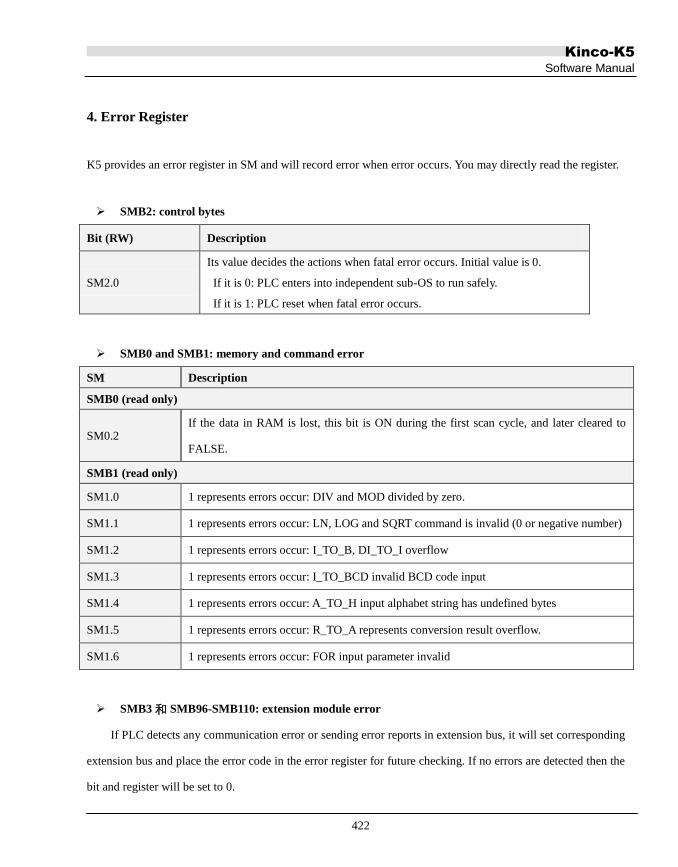
Kinco-K5
Software Manual
422
4. Error Register
K5 provides an error register in SM and will record error when error occurs. You may directly read the register.
SMB2: control bytes
Bit (RW) Description
SM2.0
Its value decides the actions when fatal error occurs. Initial value is 0.
If it is 0: PLC enters into independent sub-OS to run safely.
If it is 1: PLC reset when fatal error occurs.
SMB0 and SMB1: memory and command error
SM Description
SMB0 (read only)
SM0.2 If the data in RAM is lost, this bit is ON during the first scan cycle, and later cleared to
FALSE.
SMB1 (read only)
SM1.0 1 represents errors occur: DIV and MOD divided by zero.
SM1.1 1 represents errors occur: LN, LOG and SQRT command is invalid (0 or negative number)
SM1.2 1 represents errors occur: I_TO_B, DI_TO_I overflow
SM1.3 1 represents errors occur: I_TO_BCD invalid BCD code input
SM1.4 1 represents errors occur: A_TO_H input alphabet string has undefined bytes
SM1.5 1 represents errors occur: R_TO_A represents conversion result overflow.
SM1.6 1 represents errors occur: FOR input parameter invalid
SMB3 和 SMB96-SMB110: extension module error
If PLC detects any communication error or sending error reports in extension bus, it will set corresponding
extension bus and place the error code in the error register for future checking. If no errors are detected then the
bit and register will be set to 0.

Kinco-K5
Software Manual
423
NOTE: If PLC detects error in extension bus or extension module, it will enter STOP status and lit up ERR
indicator. It will not set corresponding register due to no executions by CPU.
SM Description
SMB3, SMB5 (read only): extension bus error signal
SMB3.0 If the 1st extension module has errors it will be set to 1.
SMB3.1 If the 2nd extension module has errors it will be set to 1.
SMB3.2 If the 3rd extension module has errors it will be set to 1.
SMB3.3 If the 4th extension module has errors it will be set to 1.
SMB3.4 If the 5th extension module has errors it will be set to 1.
SMB3.5 If the 6th extension module has errors it will be set to 1.
SMB3.6 If the 7th extension module has errors it will be set to 1.
SMB3.7 If the 8th extension module has errors it will be set to 1.
SMB5.0 If the 9th extension module has errors it will be set to 1.
SMB5.1 If the 10th extension module has errors it will be set to 1.
SMB5.2 If the 11th extension module has errors it will be set to 1.
SMB5.3 If the 12th extension module has errors it will be set to 1.
SMB5.7 If CPU detects error in extension bus communication it will be set to 1.
SMB96 - SMB110 (read only): extension bus error code
SMB96 If the 1st extension module has error then the code will be saved here.
SMB97 If the 2nd extension module has error then the code will be saved here.
SMB98 If the 3rd extension module has error then the code will be saved here.
SMB99 If the 4th extension module has error then the code will be saved here.
SMB100 If the 5th extension module has error then the code will be saved here.
SMB101 If the 6st extension module has error then the code will be saved here.
SMB102 If the 7th extension module has error then the code will be saved here.
SMB103 If the 8th extension module has error then the code will be saved here.
SMB104 If the 9th extension module has error then the code will be saved here.
SMB105 If the 10th extension module has error then the code will be saved here.
SMB106 If the 11th extension module has error then the code will be saved here.
SMB107 If the 12th extension module has error then the code will be saved here.
SMB110 Error code of CPU extension bus error is saved here.

Kinco-K5
Software Manual
424
Error Code Description
0 No error.
6 Hearbeat message of expansion modules is timeout during running. Expansion
modules send heartbeat messages to CPU periodically. If CPU does not receive
heartbeat messages of the expansion module during the set time, then it indicates
communication of the expansion module is abnormal.
10 ADC of AI tunnel conversion error
11 Adjustment value saving error
12 Adjustment value reading error
14 1st tunnel input signal of stimulation module out of measurement
15 2nd tunnel input signal of stimulation module out of measurement
16 3rd tunnel input signal of stimulation module out of measurement
17 4th tunnel input signal of stimulation module out of measurement
Figure 1 Extension Error
Code Description
0 No error
1 Communication frame format error
2 Extension bus enters into error warning status
3 Extension bus enters into error passive status
4 Extension bus enters into bus shutdown status and just recovered
5 Extension bus receiving buffer area full
6 Extension bus sending buffer full
7 CPU fails to send the report.
Figure 2 Error code of CPU extension bus communication error

Kinco-K5
Software Manual
425
5. How to restore CPU to factory setting?
The following methods are provided to restore CPU to factory setting:
The below operation will clear CPU memories, including user program, configuration data, password and
soon. CPU is reset to factory default settings.
Note: After clear, the PLC cannot realize the required function and process again. If you do not have
the program copy running in the PLC, you’d better not clear it. Otherwise you have to ask for the
equipment supplier and download again.
Steps to clear:
① Set program port of CPU to default communication parameters.
Power off CPU, and put the switch at “STOP”. Then repower on the CPU, the program port will restore to
default communication parameters: Address: 1; Baudrate: 9600; Parity: None; DataBits:8; StopBits:1.
Not: Please don‟t change the switch position before clear complete.
② Set communication parameter of PC port.
In [Communication] page, set Local parameter be the same with CPU program port.
More details please refer to 3.7 how to connect PC with Kinco-K5.
③ Execute “Clear” command
In KincoBuilder, execute [PLC]→[Clear…] menu command to clear all the data saved in CPU
memories. After execute the “Clear” command, CPU will restore to factory default setting. After
clear, the communication parameters of the program port will be set as default: Address: 1;
Baudrate: 9600; Parity: None; DataBits: 8; StopBits: 1.

Kinco-K5
Software Manual
426
6. Fault phenomenon: RUN or STOP indicators blink.
Possible reasons and countermeasures(Only suitable for K5):
Set SM2.0 to 1.
In this condition, once error occurs, PLC will automatically restart. If fatal errors keep occurring, PLC will
keep restarting. Then the RUN indictor will keep blinking. Under this condition, the STOP indicator usually
does not blinking. User could set the switch to STOP, then re-download program or clear PLC.
For some customized K5 PLC, when user update its firmware to standard K5 PLC firmware when
customized user programming is running inside.
In this condition, RUN indicators may blink. The solution is to clear PLC by KincoBuilder before update
firmware. If the STOP indicator also blinks, then users have to restore to firmware matched with user program,
then clear PLC or contact with us for technical support directly.
Hardware damage
There are kinds of hardware damages. EEPROM damage may lead to fatal error, but won‟t lead
RUN/STOP indicators blink. Memory chip damage might lead RUN/STOP indicators blink. MCU chip damage
might lead all the indicators off. If there is no lightning stoke or voltage vibration and only for normal use
hardwares seldom get damaged.

Kinco-K5
Software Manual
427
7. Fault phenomenon: Upon K5 PLC power on, RUN/STOP/ERR indicators are all ON.
The reason is that self-inspection upon power on fail:
K5 PLC EEPROM is totally damaged
Kinds of data is saved in EEPROM, including boot data. When EEPROM is damaged, PLC cannot read
the boot code.
User changed EEPROM by themselves.
Kind of data is saved in EEPROM, including boot data. If user changes new EEPROM, all the data will be
lost. Then PLC cannot read the boot code.
User changed MCU by themselves.
It is forbidden that users change MCU or EEPROM by themselves, which is for protecting intellectual
property of manufacturer.
If users changed EEPROM or MCU, then users need to change them back.
For other conditions, please return faulty models to the factory.

Kinco-K5
Software Manual
428
Appendix E Definition of SM Area
This Appendix describes the definition of system register area, SM area. This area is used to assist Kinco-K5 to
realize certain functions. You may also use it to read PLC status.
1. SMB0: system status byte
Sm0.0-SM0.7 is valued by CPU software and cannot be controlled by user. You can only call some
functions (read only):
Bit Description
SM0.0 Always be ON
SM0.1 ON during the first scan cycle only. Usually used for some initializations.
SM0.2 If the data in RAM is lost, this bit is ON during the first scan cycle, and later
cleared to FALSE.
SM0.3 Provide a pulse train (50% duty cycle) with a cycle time of 1s.
SM0.4 Provide a pulse train (50% duty cycle) with a cycle time of 2s.
SM0.5 Provide a pulse train (50% duty cycle) with a cycle time of 4s.
SM0.6 Provide a pulse train (50% duty cycle) with a cycle time of 60s.

Kinco-K5
Software Manual
429
2. SMB2: system control byte
Bit Description
SM2.0
Its value decides the actions taken when fatal errors occur. Initial value is 0.
If it is 0: PLC enters into sub-OS to run safely
If it is 1: PLC resets
SM2.1
Its value decides the status of AI/AO tunnels. Initial value is 0.
If it is 0: body AI/AO tunnel run normally
If it is 1: body AI/AO tunnel enters into adjustment

Kinco-K5
Software Manual
430
3. Communication Port Reset
K5 provides function to reset communication port (PORT0, PORT1 and PORT2). After reset K5 will clear the
buffer area of the communication ports and start initialization. After reset the parameters and functions of the
port will remain the same.
Control Register and Status Register
Bit Value Description
PORT 0 PORT 1 PORT 2
SM87.0 SM187.0 SM287.0 1 Set the two bits to certain value and use RCV command.
SM87.7 SM187.7 SM287.7 0
SM4.0 SM4.1 SM4.2 - After success reset K5 will value the bit to 1. It requires manual
reset
Reset (PORT0 as example)
1) (Optional) Set SM4.0 to 0.
2) Set SM87.7 to 0 and SM87.0 to 1.
3) Call RCV and set its PORT parameters as the communication number. Need to be valued to 0.
4) (Optional) Check SM4.0. If 1 means success reset, other operation according to the need of the
communication port.
Example
Let‟s illustrate how to reset the PORT1. The example program adopted IL language, the user can copy it to the
editor of KincoBuilder and perform 【Project】→【LD】menu commands into ladder diagram.
(* Network 0 *)
(*Use rise change of I0.0 to trigger PORT1 resetting*)
(*RCV command will not affect the resetting.*)

Kinco-K5
Software Manual
431
LD %I0.0
R_TRIG
MOVE B#0, %SMB4
AND B#16#7F, %SMB187
OR B#16#1, %SMB187
RCV %VB222, 1
(* Network 1 *)
(*After resetting you may delay until PORT1 stays stable and continue operation, in theory, don‟t delay is also
OK.*)
(*PORT1 will enter into receiving status after resetting*)
LD %SM4.1
TON T4, 3
OR B#16#80, %SMB187
RCV %VB222, 1
R %SM4.1

Kinco-K5
Software Manual
432
4. Other functional variables
SM Description
SMB6 Read-only. Save the last PLC scanning time. Unit: ms.
SMW10
Read-only. Save voltage of back-up battery. Unit: 0.01V.
If the power supply of back-up battery be lower than 2.6V constantly, PLC will warn
“Low Back-up Battery”
SMB274-SMB285 The composite value of 12 bytes represents the ID value of the CPU module. Each
CPU module is given a unique ID value.

Kinco-K5
Software Manual
433
5. SMD12 and SMD16: Timer Interrupt Events List
K5 can provide two Timer Interruptions based on 0.1ms: Timer Interrupt 0 with Event No. 3; Time Interrupt 1
with Event No. 4.
SMD12 is used to define the cycle of Timer Interruption 0, with a unit of 0.1ms. If SMD12 is set to 0 then
Timer Interrupt 0 will be forbidden. The default value of SMD12 is 0;
SMD16 is used to define the cycle of Timer Interruption 1, with a unit of 0.1ms. If SMD12 is set to 0 then
Timer Interrupt 0 will be forbidden. The default value of SMD16 is 0;
Timer Interrupt will generate periodically and you may use it to complete periodical tasks. Timer Interrupt will
not be affected by PLC scanning period and can be used for precise timing.

Kinco-K5
Software Manual
434
Appendix F CANOpen Master
CANopen is a networking system based on the CAN serial bus. It was originally designed for motion-oriented
industrial control systems, such as handling systems, but it can also be used in other application fields, e.g.
vehicles, medical equipment and building automation.
1. CANOpen Communication Objects
CANOpen Application Layer and Communication Profile (CiA DS-301) is suitable for all CANOpen devices.
In DS-301, various communication objects are defined, and they are described by the services and protocols.
Here we introduce some commonly used communication objects.
1.1 Network management (NMT)
The network management (NMT) is CANopen device oriented and follows a master-slave structure. It requires
one device in the network, which fulfills the function of the NMT Master. The other nodes are NMT Slaves. An
NMT slave is uniquely identified in the network by its node-ID, a value in the range of [1..127].
NMT objects are used for executing NMT services. Through NMT services, CANopen devices are initialized,
started, monitored, reset or stopped.
1.1.1 NMT Node Control
Through node control services, the NMT master controls the NMT state of the NMT slaves. The NMT state
attribute is one of the values {Stopped, Pre-operational, Operational, Initialisation}.
The format of the node control message is as following.
Master -> Slave
COB-ID Byte 0 Byte 1
0x000 CS(Command Specifier) Node ID
The Node-ID defines the destination of the message. If it is zero the message addresses all NMT slaves.

Kinco-K5
Software Manual
435
The Command Specifier (CS) represents the following services:
Start Remote Node (CS=1),
Stop Remote Node (CS=2),
Enter Pre-Operational (CS=128),
Reset Node (CS=129) and
Reset Communication (CS=130).
1.1.2 NMT Error Control
The error control services supervise the nodes and network communication status. There exist two possibilities
to perform error control.
The Node Guarding is achieved by transmitting guarding requests by the NMT master. If a NMT slave has not
responded within a defined span of time (node life time) or if the NMT slave‟s communication status has
changed, the NMT master informs its NMT master application about that event.
The Heartbeat mechanism for a CANopen device is established by cyclically transmitting the heartbeat message
by the heartbeat producer. If the heartbeat cycle fails for the heartbeat producer the local application on the
heartbeat consumer will be informed about that event.
It is highly recommend to implement the heartbeat protocol for new device designs.
NMT Node Guarding
The NMT master transmits a special remote frame, within which there is no data.
COB-ID
0x700 + Node ID
The corresponding slave responds:
COB-ID Byte 0
0x700 + Node ID Bit7:toggle-bit.
Bit0-6:the state of the slave.
4 STOPPED; 5 Operational; 127 Pre-Operational.

Kinco-K5
Software Manual
436
Heartbeat
A heartbeat producer transmits a heartbeat message cyclically. One or more heartbeat consumer receives the
indication. The heartbeat consumer guards the reception of the heartbeat within the heartbeat consumer time. If
the heartbeat is not received within the heartbeat consumer time a heartbeat event will be generated.
COB-ID Byte 0
0x700 + Node ID the state of the slave.
4 STOPPED; 5 Operational; 127 Pre-Operational.
1.2 Service Data Object (SDO)
A SDO is providing direct access to object entries of a CANopen device's object dictionary through index and
sub-index. By means of a SDO a peer-to-peer communication channel between two CANopen devices is
established. Always the client initiates an SDO transfer for any type of transfer. The owner of the accessed object
dictionary is the server of the SDO.
SDOs allow to transfer data of any size. The transfer of messages of less than 5 data bytes an „expedited‟
transfer may be performed. The transfer of messages of more than 4 data bytes has to be performed by means of
the „segmented‟ transfer. The „expedited transfer‟ messages are as following.
Request, Client -> Server:
COB-ID Byte 0 Byte 1-2 Byte 3 Byte 4-7
0x600 + Node ID CS index Sub-index Data
Response,Server -> Client:
COB-ID Byte 0 Byte 1-2 Byte 3 Byte 4-7
0x580 + Node ID CS index Sub-index Data
1.3 Process Data Object (PDO)
The real-time data transfer is performed by means of "Process Data Objects (PDO)". PDO communication can
be described by the producer/consumer model. Process data can be transmitted from one device (producer) to

Kinco-K5
Software Manual
437
one another device (consumer) or to many other devices (broadcasting). PDOs are transmitted in a
non-confirmed mode.
There are two kinds of use for PDO. The first is data transmission and the second data reception. It is
distinguished in Transmit-PDO (TPDO) and Receive-PDO (RPDO). CANopen devices supporting TPDO are
PDO producer and CANopen devices supporting RPDO are called PDO consumer.
PDO is performed with no protocol overhead. The contents and parameters of a PDO are defined by the user
through a network configuration tool.
PDO are described by the PDO communication parameter and the PDO mapping parameter. The PDO
communication parameter describes the communication capabilities of the PDO. The PDO mapping parameter
contains information about the contents of the PDO. Here we describe the PDO communication parameters.
COB-ID
The COB-ID of the PDO, and it is the unique identifier.
Transmission Type
It represents the triggering mode of PDO transmission. It is an 8-bit unsigned integer value.
Event- and timer-driven
Message transmission is either triggered by the occurrence of an application-specific event specified in the
device profile, application profile or manufacturer-specific, or if a specified time (event-time) has elapsed
without occurrence of an event.
Transmission type 254 means manufacturer-specific event.
Transmission type 255 means that the event is specified in the device profile, application profile.
Remotely requested
The transmission of an event-driven PDO is initiated on receipt of a RTR initiated by a PDO consumer.
The transmission type value is 252 or 253.
Synchronously triggered
Message transmission is triggered by the occurrence of the SYNC object. The trigger condition is the number of
Sync and optionally an internal event.
Cyclic (transmission types 1-240) means that the transmission of the PDO shall be related to the SYNC object.

Kinco-K5
Software Manual
438
Acyclic (transmission type 0) means that the message shall be transmitted synchronously with the SYNC object
but not periodically.
Transmission type 252 means that the transmission of the PDO shall be related to the SYNC object and RTR.
Inhibit Time
To guarantee that no starvation on the network occurs for communication objects with low priorities, PDOs can
be assigned an inhibit time. The inhibit time defines the minimum time that has to elapse between two
consecutive invocations of a PDO.
The value of 0 shall disable the inhibit time.
Event Timer
It is an 8-bit unsigned integer value. The value of 0 shall disable the event-timer.
If the specified time (event-time) has elapsed, PDO transmission shall be triggered, even without occurrence of
a specific event.
2. The CANOpen master function of Kinco-K5
Besides K504, all other CPU modules can combine with K541 to serve as a CANOpen master.
2.1 Main Features
Supporting CAN2.0A, and accords with DS301 V4.2.0.
Supporting NMT (Network Management) services and serving as a NMT master.
Supporting normal expedited SDO as a client, and providing SDO_READ and SDO_WRITE instructions.
Supporting for 72 CANOpen slaves.
At most 8 TPDOs and 8 RPDOs for a slave,and 256 TPDOs and 256 RPDOs for all.
Supporting Heartbeat protocol and Node-guarding protocol.
Network error management

Kinco-K5
Software Manual
439
2.2 How to use?
2.2.1 CANOpen network configuration tool
In Kincobuilder, enter the [Hardware] window, then click and select the CPU module in the upper table, and
then click [CANOpen] tab in the under window, and now you can configure the network and all the devices.
2.2.2 Manage EDS files
In [CANOpen]->[Network Settings] window, there are 4 buttons for operating eds files:
[Import EDS…]: Click this button, then select an eds file to import it into Kincobuilder. After importing an
eds file, the corresponding device appears in the under [Available Devices] tree list.
[Delete]: Click and select a device in the [Available Devices], then click [Delete] button, and this device
is deleted from the [Available Devices] tree list, also its eds file is deleted from Kincobuilder.
[Export All EDS]:
[Import All EDS]:
2.2.3 Configuration Steps of a CANOpen network
1) Configure the global parameters
Enter [Global Settings] tab, as the following picture:
[Baudrate]: Select the master‟s baudrate. Notice that all devices in a network must use the same baudrate.
[SDO Timeout]: Set a time for waiting for the SDO response after the master transmits a SDO request. If the
master doesn‟t receive the SDO response until this time has elapsed, the master shall report an error. Usually
this value is less than 100ms.
[Configure slaves at startup]: The master controls the NMT state of all the slaves. Besides, if this checkbox is

Kinco-K5
Software Manual
440
checked, then at startup the master also transmits messages to configure all slaves (such as PDO mapping)
according to their configurations.
2) Configure all slaves
Enter [Network Setting] tab and continue to configure the slave nodes and their parameters.
All the functional buttons correspond to a right-click menu. Users right click mouse on related location,
corresponding menu will pop up.
a) Add a slave device into the network:
Select a slave device and double click it from the left tree list, then this device is added into the network and
listed in the right table.
b) Configure the slave’s parameter (such as ID, Error control):
In the right table, the [ID] column lists the ID of each slave. The first row is the slave of ID No.10.
After a slave device is added, the default parameter configuration will display. Slave devices are added from top
to bottom to the list by default. User could single click one row to select a slave device, then single click [UP]
and [Down] to modify its station number, or single click [Delete] to delete the slave device.
[Error Control] is used to select a NMT Error Control method (NMT Node Guarding or Heartbeat). If a slave
supports these two methods, it is highly recommended to use Heartbeat.
[Control Cycle] is the cycle time of node guarding or heartbeat. It is recommended to set this time to be more
than 2000ms.
[HB consumer time] is the heartbeat consumer time. The Heartbeat Consumer guards the reception of the

Kinco-K5
Software Manual
441
Heartbeat within the Heartbeat consumer time. If the Heartbeat is not received within this time a Heartbeat
Error will be generated. It is recommended to set this time to be more than 3000ms.
[Error treatment] is used to select a treatment method (including „None‟, „Stop the node‟ and „Stop network‟)
when the master detects an error of this slave. The slave errors that can be detected include SDO Time-out,
Node Guarding time-out, Heartbeat time-out, some Emergency objects, etc.
c) Configure the startup procedures of a slave:
Click and select a slave in the table, then click [Startup] button, now you can configure the startup procedures
of this slave.
[Reset the slave]: Whether sent “Reset Note” message before master station send configuration command to
slave station.
[Check device type: Whether read and check device information before master station send configuration
command to slave station.
[Configure NMT Error Control]: Whether configure node management type and corresponding parameters
for slave station.
[Configure PDO Mapping parameters]: Configure PDO mapping parameters of slave station.
[Configure PDO Communication parameters]: Configure PDO communication parameters of slave station.
[Start the slave]: Whether send „Start Node‟ message to slave station.

Kinco-K5
Software Manual
442
[Initialize all objects in PDO]: After slave station start, whether master station should set all PDOs of salve
station to 0.
d) Configure the PDO mappings of the slaves:
Enter the [Mapping parameters] tab and configure the PDO mappings of the slaves.
On the left hand, [All Slaves] tap lists all the slaves in the network and all the objects of each slave that can be
mapped into PDO. [Objects for TPDO] can only be mapped into TPDO, and [Objects for RPDO] can only be
mapped into RPDO. The steps of configuring a PDO are as following:
i) Click a slave in the [All Slaves] tree list, then all PDOs of this slave appear in the right table.
ii) Click and select a PDO in the table, then you can modify its communication parameters, such as
Event-timer, Inhibit time, etc.
The COB-IDs of TPDO1-4 and RPDO1-4 can‟t be modified, because they use the default COB-ID in the
pre-defined connection set of DS301. You can freely assign legal COB-IDs for TPDO5-8and RPDO5-8.
Besides, double click on any object of left list, the object will be added in to the current PDO. At the same
time, KincoBuilder assigns a V area address for the object automatically, for example: VW1006. Then users
could operate the object by operate VW1006 in the program.
iii) Repeat the above until all the PDOs of current slave station are configured.
e) Copy, paste slave station

Kinco-K5
Software Manual
443
In the [Network Setting] tab, there are [Copy], [Paste] and [Paste and reallocate] buttons.
[Copy]: Select one slave station which is already configured, then single click [Copy] button to copy all the
information of the selected slave station (All PDO mapping/communication parameters). If no PDOs are
configured for the selected slave station, then it reports copy fail.
[Paste]: After copy one slave station successfully, select one blank row and single click the [Paste] button to
paste the copied configuration information, a new station is created at the same time. Note: PDOs mapping
addresses of the new slave station are the same with source slave station, users have to modify by themselves.
[Paste and reallocate]: Operation method is the same with [Paste]. But by [Paste and reallocate], PDOs
addresses will be relocated automatically, users no need to modify by themselves.
2.3 ERR LED of K541
Usually, CAN controller chip realized fully CAN2.0 protocol. According to error detect mechanism
defined by CAN2.0, CAN controller chip could automatically detect bit error, CRC error, ACK error and so on,
and set corresponding error registers for access by external MCU.
K541 reads error registers of the CAN controller chip. Once error message is detected, ERR light will be
ON. If the error value is 0, ERR light will be OFF. So when ERR light is ON, it indicates communication is
bad and many errors occur. Once ERR light is ON, users could check from the following aspects:
1) Check whether CAN bus wiring is correct or virtual connection.
2) Whether all the nodes are with same baud rate.
3) In the CAN bus network, the 1st node and last node should connect with a 120ohm terminal resistor.
4) Whether there is strong interference source near the network.
5) It is better to set prober “Inhibit time” for frequently read/written PDOs (Position, speed and so on).