jw universal joints - timken company
TRANSCRIPT
329 UJ-
JW
Table of Contents
www.lovejoy-inc.com 329www.lovejoy-inc.com
Table of ContentsU
J
In This Section: ■ D Type
■ HD Type
■ D Type Stainless
■ NB (Needle Bearing) Type
■ LOJ Type
■ DD and DDX Type
■ Universal Joint Boots
UJ-1
Universal Joints
JW
Table of Contents
330 630-852-0500
When using Lovejoy products, you must follow these instructions and take the following precautions. Failure
to do so may cause the power transmission product to break and parts to be thrown with sufficient force to
cause severe injury or death.
Refer to this Lovejoy Catalog for proper selection, sizing, horsepower, torque range, and speed range
of power transmission products, including elastomeric elements for couplings. Follow the installation
instructions included with the product, and in the individual product catalogs for proper installation of power
transmission products. Do not exceed catalog ratings.
During start up and operation of power transmission product, avoid sudden shock loads. Coupling assembly
should operate quietly and smoothly. If coupling assembly vibrates or makes beating sound, shut down
immediately, and recheck alignment. Shortly after initial operation and periodically thereafter, where
applicable, inspect coupling assembly for: alignment, wear of elastomeric element, bolt torques, and flexing
elements for signs of fatigue. Do not operate coupling assembly if alignment is improper, or where applicable,
if elastomeric element is damaged, or worn to less than 75% of its original thickness.
Do not use any of these power transmission products for elevators, man lifts, or other devices that carry
people. If the power transmission product fails, the lift device could fall resulting in severe injury or death.
For all power transmission products, you must install suitable guards in accordance with OSHA and
American Society of Mechanical Engineers Standards. Do not start power transmission product before
suitable guards are in place. Failure to properly guard these products may result in severe injury or death
from personnel contacting moving parts or from parts being thrown from assembly in the event the power
transmission product fails.
If you have any questions, contact the Lovejoy Engineering Department at 1-630-852-0500.
Safety Warning
Table of Contents
UJ-2
Universal Joints
UJ
331www.lovejoy-inc.com
Table of Contents
UJ-3
Universal Joints
Overview ......................................................................................................................................332 ..................... UJ-4
Pin & Block > Selection Process .................................................................................................333 ..................... UJ-5
Application Service Factors > Selection Data .............................................................................334 ..................... UJ-6
D, HD and NB Type Running Curves > Selection Data ..............................................................335 ..................... UJ-7
D and HD Type > Dimensional Data............................................................................................336 ..................... UJ-8
D 303 Stainless and NB Type > Dimensional Data .....................................................................337 ..................... UJ-9
DD and DDX Type > Dimensional Data.......................................................................................338 ................... UJ-10
LOJ and JR-4 Types / Boots > Dimensional Data .......................................................................339 ................... UJ-11
Running Section
Page No. Page No.
UJ
332 630-852-0500
Table of Contents
UJ-4
Universal Joints
Overview
Lovejoy Pin & Block and Needle Bearing Industrial Universal Joints
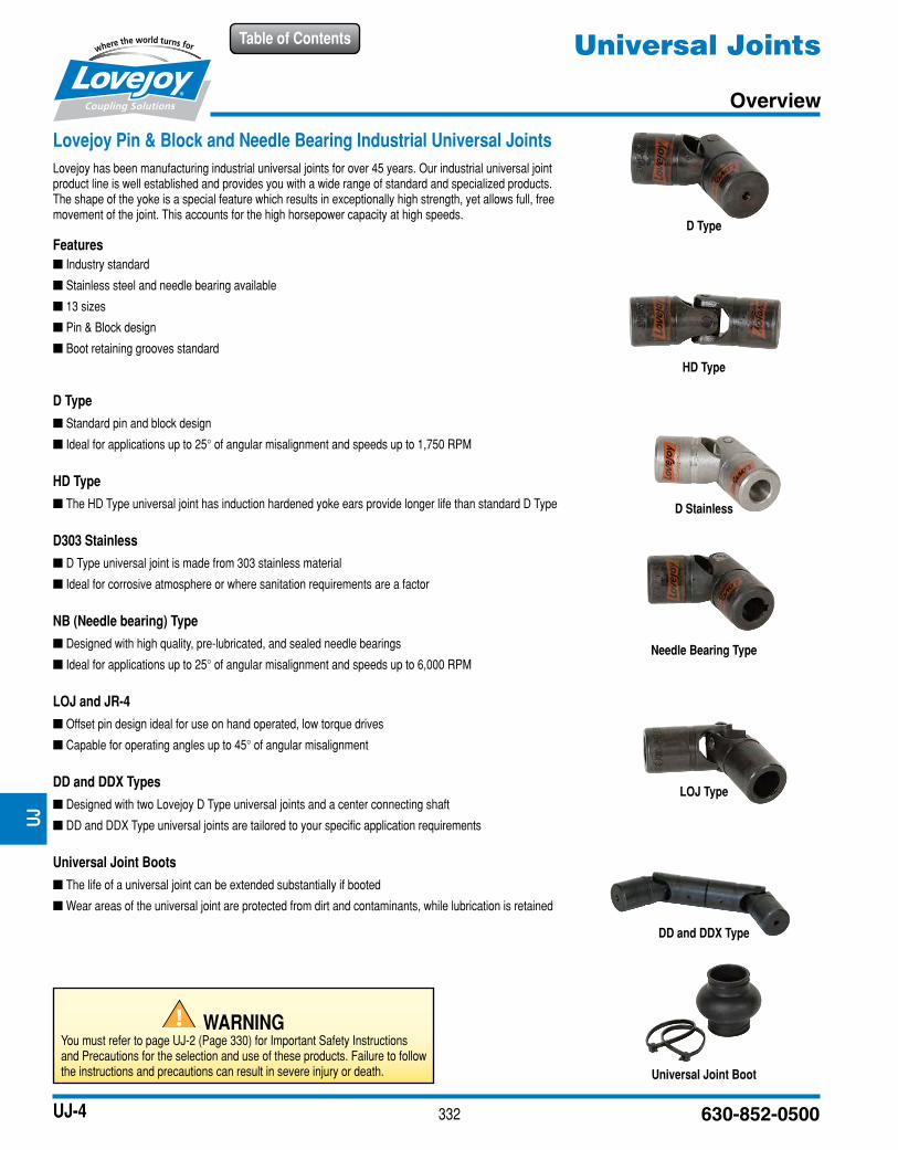
Lovejoy has been manufacturing industrial universal joints for over 45 years. Our industrial universal joint product line is well established and provides you with a wide range of standard and specialized products. The shape of the yoke is a special feature which results in exceptionally high strength, yet allows full, free movement of the joint. This accounts for the high horsepower capacity at high speeds.
Features
■ Industry standard
■ Stainless steel and needle bearing available
■ 13 sizes
■ Pin & Block design
■ Boot retaining grooves standard
D Type
■ Standard pin and block design
■ Ideal for applications up to 25° of angular misalignment and speeds up to 1,750 RPM
HD Type
■ The HD Type universal joint has induction hardened yoke ears provide longer life than standard D Type
D303 Stainless
■ D Type universal joint is made from 303 stainless material
■ Ideal for corrosive atmosphere or where sanitation requirements are a factor
NB (Needle bearing) Type
■ Designed with high quality, pre-lubricated, and sealed needle bearings
■ Ideal for applications up to 25° of angular misalignment and speeds up to 6,000 RPM
LOJ and JR-4
■ Offset pin design ideal for use on hand operated, low torque drives
■ Capable for operating angles up to 45° of angular misalignment
DD and DDX Types
■ Designed with two Lovejoy D Type universal joints and a center connecting shaft
■ DD and DDX Type universal joints are tailored to your specific application requirements
Universal Joint Boots
■ The life of a universal joint can be extended substantially if booted
■ Wear areas of the universal joint are protected from dirt and contaminants, while lubrication is retained
D Type
HD Type
D Stainless
Needle Bearing Type
LOJ Type
Universal Joint Boot
DD and DDX Type
UJ
WARNINGYou must refer to page UJ-2 (Page 330) for Important Safety Instructions and Precautions for the selection and use of these products. Failure to follow the instructions and precautions can result in severe injury or death.
333
Table of Contents
www.lovejoy-inc.com UJ-5
Universal JointsPin & Block
Selection Process
Notes: n * indicates: This is not a recommended operating torque. n 3 indicates: Square and hex bores are measured across the flats. n Operation of all universal joints is determined by the angle/speed combinations of the application. Consult Lovejoy Engineering for specific limitations
and recommendations. n Applications that fall outside the limitations of these tables should be referred Lovejoy Engineering for assistance.
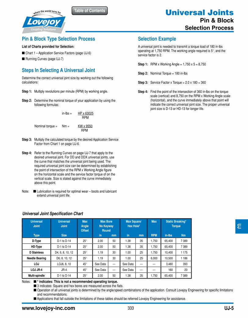
Pin & Block Type Selection Process
List of Charts provided for Selection:
■ Chart 1 – Application Service Factors (page UJ-6)
■ Running Curves (page UJ-7)
Steps In Selecting A Universal Joint
Determine the correct universal joint size by working out the following calculations:
Step 1: Multiply revolutions per minute (RPM) by working angle.
Step 2: Determine the nominal torque of your application by using the following formulas:
in-lbs = HP x 63025 RPM
Nominal torque = Nm = KW x 9550 RPM
Step 3: Multiply the calculated torque by the desired Application Service Factor from Chart 1 on page UJ-6.
Step 4: Refer to the Running Curves on page UJ-7 that apply to the desired universal joint. For DD and DDX universal joints, use the curve that matches the universal joint being used. The required universal joint size can be determined by establishing the point of intersection of the RPM x Working Angle figure on the horizontal scale and the service factor torque of on the vertical scale. Size is stated against the curve immediately above this point.
Note: n Lubrication is required for optimal wear – boots and lubricant extend universal joint life.
Selection Example
A universal joint is needed to transmit a torque load of 180 in-lbs operating at 1,750 RPM. The working angle required is 5°, and the service factor is 2.
Step 1: RPM x Working Angle = 1,750 x 5 = 8,750
Step 2: Nominal Torque = 180 in-lbs
Step 3: Service Factor x Torque = 2.0 x 180 = 360
Step 4: Find the point of the intersection of 360 in-lbs on the torque scale (vertical) and 8,750 on the RPM x Working Angle scale (horizontal), and the curve immediately above that point will indicate the correct universal joint size. The proper universal joint size is D-13 or HD-13 for longer life.
Universal Joint Specification Chart
Universal Universal Max Max Bore Max Square/ Max Static Breaking*
Joint Joint Angle No Keyway Hex Hole3 Torque
Offset Round
Type Size in mm in mm RPM in-lbs Nm
D-Type D-1 to D-14 25° 2.00 50 1.38 35 1,750 65,400 7 389
HD-Type D-1 to D-14 25° 2.00 50 1.38 35 1,750 65,400 7 389
D Stainless D4, 6, 8, 10, 12 25° 1.19 30 1.00 25 1,750 10,400 1 175
Needle Bearing D6, 8, 10, 12 25° 1.19 30 1.00 25 6,000 10,500 1 186
LOJ LOJ6, 8, 10 45° See Data — See Data — — 3,480 393
LOJ JR-4 JR-4 45° See Data — See Data — — 180 20
Multi-spindle D-1 to D-14 25° 2.00 50 1.38 35 1,750 65,400 7 389
UJ
334 630-852-0500
Table of Contents
UJ-6
Universal JointsApplication Service Factors
Selection Data
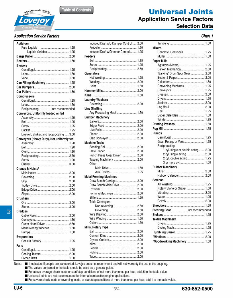
Application Service Factors Chart 1
Agitators
Pure Liquids .....................................1.25
Liquids Variable ............................1.25
Barge Puller ..............................................2.00
Beaters ......................................................1.50
Blowers
Centrifugal ............................................1.25
Lobe .....................................................1.50
Vane .....................................................1.50
Can Filling Machinery ..............................1.25
Car Dumpers .............................................2.50
Car Pullers ................................................1.50
Compressors
Centrifugal ............................................1.25
Lobe .....................................................1.50
Reciprocating .................not recommended
Conveyors, Uniformly loaded or fed
Assembly .............................................1.25
Belt ......................................................1.25
Screw ...................................................1.25
Bucket ..................................................1.25
Live roll, shaker, and reciprocating .....3.00
Conveyors (Heavy Duty), Not uniformly fed
Assembly .............................................1.20
Belt ......................................................1.20
Oven.....................................................1.20
Reciprocating .......................................2.50
Screw ...................................................1.20
Shaker ..................................................3.00
Cranes & Hoists1
Main Hoists ..........................................2.00
Reversing .............................................2.00
Skip ......................................................2.00
Trolley Drive .........................................2.00
Bridge Drive .........................................2.00
Slope ....................................................2.00
Crushers
Ore ......................................................3.00
Stone ....................................................3.00
Dredges
Cable Reels .........................................2.00
Conveyors ............................................1.50
Cutter Head Drives ..............................2.50
Maneuvering Winches .........................1.50
Pumps ..................................................1.50
Evaporators
Consult Factory ....................................1.25
Fans
Centrifugal ............................................1.25
Cooling Towers.....................................2.00
Forced Draft .........................................1.50
Induced Draft w/o Damper Control .....2.00
Propellor ...............................................1.50
Induced Draft w/Damper Control .........1.25
Feeders
Belt ......................................................1.25
Screw ...................................................1.25
Reciprocating .......................................2.50
Generators
Not Welding .........................................1.25
Welding ................................................2.00
Hoist .....................................................1.50
Hammer Mills ............................................2.00
Kilns ......................................................1.50
Laundry Washers
Reversing .............................................2.00
Line Shafting
Any Processing Mach ..........................1.50
Lumber Machinery
Barkers .................................................2.00
Edger Feed .........................................2.00
Live Rolls..............................................2.00
Planer ...................................................2.00
Slab Conveyor .....................................2.00
Machine Tools
Bending Roll .........................................2.00
Plate Planer ........................................2.00
Punch Press Gear Driven ....................2.00
Tapping Machinery ..............................2.00
Other
Main Drive.....................................1.50
Aux. Drives ...................................1.25
Metal Forming Machines
Draw Bench Carriage ...........................2.00
Draw Bench Main Drive .......................2.00
Extruder ...............................................2.00
Forming Machinery ..............................2.00
Slitters ..................................................1.50
Table Conveyors
Non-reversing ...............................2.50
Reversing .....................................2.50
Wire Drawing .......................................2.00
Wire Winding .......................................1.50
Coilers ..................................................1.50
Mills, Rotary Type
Ball ......................................................2.00
Cement Kilns .......................................2.00
Dryers, Coolers ....................................2.00
Kilns .....................................................2.00
Pebble ..................................................2.00
Rolling ..................................................2.00
Tube .....................................................2.00
Tumbling ..............................................1.50
Mixers
Concrete, Continous ............................1.75
Muller ...................................................1.50
Paper Mills
Agitators (Mixers) .................................1.25
Barker, Mechanical ..............................2.00
“Barking” Drum Spur Gear ...................2.50
Beater & Pulper ....................................2.00
Calenders .............................................1.50
Converting Machines ...........................1.25
Conveyors ............................................1.25
Dresses ................................................2.00
Dryers...................................................1.50
Jordans ................................................2.00
Log Haul ...............................................2.00
Reel ..................................................... 1.25
Super Calenders ..................................1.50
Winder ..................................................1.25
Printing Presses .......................................1.50
Pug Mill ..................................................... 1.75
Pumps
Centrifugal ...........................................1.25
Gear, Rotary, or Vane ...........................1.25
Reciprocating
1 cyl. single or double acting ....... 2.00
2 cyl. single acting ....................... 2.00
2 cyl. double acting ...................... 1.75
3 or more cyl. ............................... 1.50
Rubber Machinery
Mixer ................................................... 2.50
Rubber Calender ................................. 2.00
Screens
Air Washing ..........................................1.25
Rotary Stone or Gravel ........................1.50
Vibrating ...............................................2.50
Water ...................................................1.25
Grizzly ..................................................2.00
Shredders ..................................................1.50
Steering Gear ......................not recommended
Stokers .................................................... 1.25
Textile Machinery
Dryers...................................................1.25
Dyeing Mach. .......................................1.25
Tumbling Barrel .......................................1.75
Windlass ...................................................2.00
Woodworking Machinery ........................1.50
Notes: n 1 indicates: If people are transported, Lovejoy does not recommend and will not warranty the use of the coupling. n The values contained in the table should be used as a general guide. n For above average shock loads or start/stop conditions of not more than once per hour, add .5 to the table value. n Universal joints are not recommended for internal combustion engine applications. n For severe shock loads or reversing loads, or start/stop conditions of more than once per hour, add 1 to the table value.
UJ
335
Table of Contents
www.lovejoy-inc.com UJ-7
Universal JointsD, HD and NB Type Running Curves
Selection Data
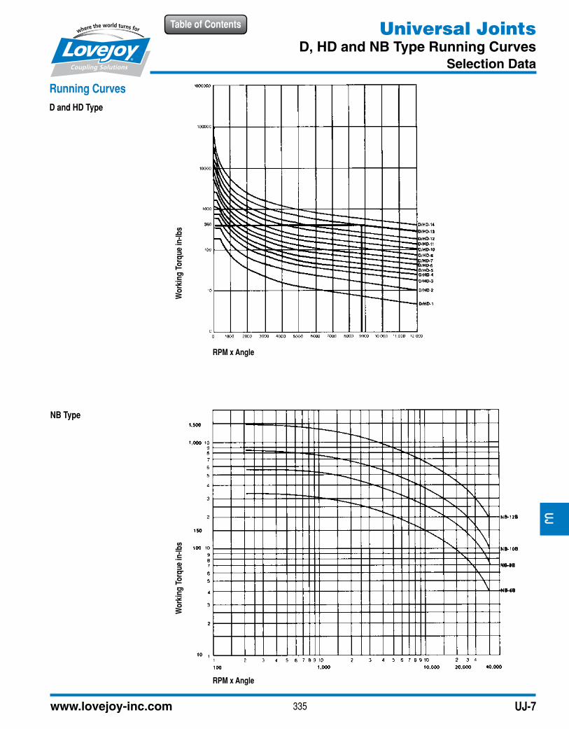
Running Curves
D and HD Type
Wo
rkin
g T
orq
ue
in-l
bs
Wo
rkin
g T
orq
ue
in-l
bs
RPM x Angle
RPM x Angle
NB Type
UJ
336 630-852-0500
Table of Contents
UJ-8
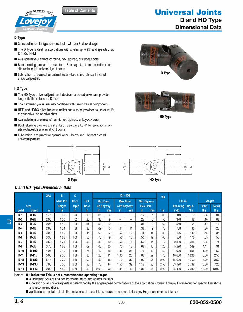
D and HD Type Dimensional Data
OAL E C ID1 - ID2OD
Main Pin Bore Std Max Bore Max Bore Max Square/ Static* Weight
Size Height Depth Bore No Keyway with Keyway Hex Hole3 Breaking Torque Solid Bored
Solid Bored in in in in in mm in mm in mm in in-lb Nm lbs lbs
D-1 D-1B 1.75 .88 .56 .19 .25 6 – – .19 4 .38 110 12 .05 .04
D-2 D-2B 2.00 1.00 .62 .25 .38 9 – – .25 6 .50 378 42 .10 .08
D-3 D-3B 2.25 1.12 .68 .31 .50 12 – – .31 8 .62 540 61 .17 .15
D-4 D-4B 2.68 1.34 .88 .38 .62 15 .44 11 .38 9 .75 768 86 .30 .25
D-5 D-5B 3.00 1.50 .88 .44 .69 17 .50 12 .44 11 .88 1,176 132 .45 .37
D-6 D-6B 3.38 1.68 1.00 .50 .75 19 .56 13 .50 12 1.00 1,560 176 .65 .55
D-7 D-7B 3.50 1.75 1.00 .56 .88 22 .62 15 .56 14 1.12 2,880 325 .85 .71
D-8 D-8B 3.75 1.88 1.06 .62 1.00 25 .75 18 .62 15 1.25 5,220 589 1.11 .94
D-10 D-10B 4.25 2.12 1.18 .75 1.12 28 .88 21 .75 19 1.50 7,920 895 1.80 1.50
D-11 D-11B 5.00 2.50 1.38 .88 1.25 31 1.00 25 .88 22 1.75 10,680 1 206 3.00 2.50
D-12 D-12B 5.44 2.72 1.50 1.00 1.50 38 1.19 30 1.00 25 2.00 15,600 1 762 4.20 3.50
D-13 D-13B 7.00 3.50 2.00 1.25 1.75 44 1.50 39 1.12 28 2.50 33,120 3 742 8.50 7.20
D-14 D-14B 9.06 4.53 2.75 1.50 2.00 50 1.81 48 1.38 35 3.00 65,400 7 389 16.00 13.00
Notes: n * indicates: This is not a recommended operating torque. n 3 indicates: Square and hex bores are measured across the flats. n Operation of all universal joints is determined by the angle/speed combinations of the application. Consult Lovejoy Engineering for specific limitations
and recommendations. n Applications that fall outside the limitations of these tables should be referred to Lovejoy Engineering for assistance.
Universal JointsD and HD Type
Dimensional Data
D Type
■ Standard industrial type universal joint with pin & block design
■ The D Type is ideal for applications with angles up to 25° and speeds of up to 1,750 RPM
■ Available in your choice of round, hex, splined, or keyway bore
■ Boot retaining grooves are standard. See page UJ-11 for selection of on-site replaceable universal joint boots
■ Lubrication is required for optimal wear – boots and lubricant extend universal joint life
HD Type
■ The HD Type universal joint has induction hardened yoke ears provide longer life than standard D Type
■ The hardened yokes are matched fitted with the universal components
■ HDD and HDDX drive line assemblies can also be provided to increase life of your drive line or drive shaft
■ Available in your choice of round, hex, splined, or keyway bore
■ Boot retaining grooves are standard. See page UJ-11 for selection of on-site replaceable universal joint boots
■ Lubrication is required for optimal wear – boots and lubricant extend universal joint life
D Type
HD Type
D Type HD Type
UJ
337
Table of Contents
www.lovejoy-inc.com UJ-9
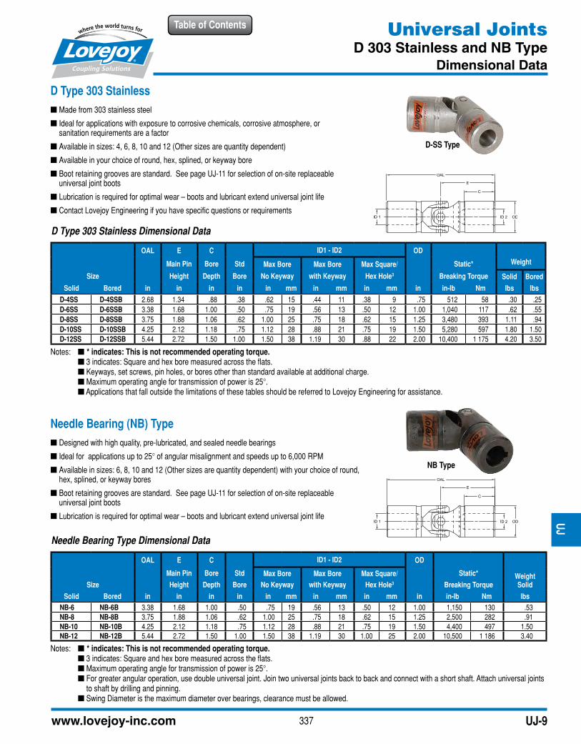
D Type 303 Stainless Dimensional Data
OAL E C ID1 - ID2 OD
WeightMain Pin Bore Std Max Bore Max Bore Max Square/ Static*
Size Height Depth Bore No Keyway with Keyway Hex Hole3 Breaking Torque Solid Bored
Solid Bored in in in in in mm in mm in mm in in-lb Nm lbs lbs
D-4SS D-4SSB 2.68 1.34 .88 .38 .62 15 .44 11 .38 9 .75 512 58 .30 .25
D-6SS D-6SSB 3.38 1.68 1.00 .50 .75 19 .56 13 .50 12 1.00 1,040 117 .62 .55
D-8SS D-8SSB 3.75 1.88 1.06 .62 1.00 25 .75 18 .62 15 1.25 3,480 393 1.11 .94
D-10SS D-10SSB 4.25 2.12 1.18 .75 1.12 28 .88 21 .75 19 1.50 5,280 597 1.80 1.50
D-12SS D-12SSB 5.44 2.72 1.50 1.00 1.50 38 1.19 30 .88 22 2.00 10,400 1 175 4.20 3.50
Needle Bearing Type Dimensional Data
OAL E C ID1 - ID2 OD
WeightMain Pin Bore Std Max Bore Max Bore Max Square/ Static*
Size Height Depth Bore No Keyway with Keyway Hex Hole3 Breaking Torque Solid
Solid Bored in in in in in mm in mm in mm in in-lb Nm lbs
NB-6 NB-6B 3.38 1.68 1.00 .50 .75 19 .56 13 .50 12 1.00 1,150 130 .53
NB-8 NB-8B 3.75 1.88 1.06 .62 1.00 25 .75 18 .62 15 1.25 2,500 282 .91
NB-10 NB-10B 4.25 2.12 1.18 .75 1.12 28 .88 21 .75 19 1.50 4,400 497 1.50
NB-12 NB-12B 5.44 2.72 1.50 1.00 1.50 38 1.19 30 1.00 25 2.00 10,500 1 186 3.40
Notes: n * indicates: This is not recommended operating torque. n 3 indicates: Square and hex bore measured across the flats. n Keyways, set screws, pin holes, or bores other than standard available at additional charge. n Maximum operating angle for transmission of power is 25°. n Applications that fall outside the limitations of these tables should be referred to Lovejoy Engineering for assistance.
Notes: n * indicates: This is not recommended operating torque. n 3 indicates: Square and hex bore measured across the flats. n Maximum operating angle for transmission of power is 25°. n For greater angular operation, use double universal joint. Join two universal joints back to back and connect with a short shaft. Attach universal joints
to shaft by drilling and pinning. n Swing Diameter is the maximum diameter over bearings, clearance must be allowed.
D Type 303 Stainless
■ Made from 303 stainless steel
■ Ideal for applications with exposure to corrosive chemicals, corrosive atmosphere, or sanitation requirements are a factor
■ Available in sizes: 4, 6, 8, 10 and 12 (Other sizes are quantity dependent)
■ Available in your choice of round, hex, splined, or keyway bore
■ Boot retaining grooves are standard. See page UJ-11 for selection of on-site replaceable universal joint boots
■ Lubrication is required for optimal wear – boots and lubricant extend universal joint life
■ Contact Lovejoy Engineering if you have specific questions or requirements
Needle Bearing (NB) Type
■ Designed with high quality, pre-lubricated, and sealed needle bearings
■ Ideal for applications up to 25° of angular misalignment and speeds up to 6,000 RPM
■ Available in sizes: 6, 8, 10 and 12 (Other sizes are quantity dependent) with your choice of round, hex, splined, or keyway bores
■ Boot retaining grooves are standard. See page UJ-11 for selection of on-site replaceable universal joint boots
■ Lubrication is required for optimal wear – boots and lubricant extend universal joint life
NB Type
Universal JointsD 303 Stainless and NB Type
Dimensional Data
D-SS Type
UJ
338 630-852-0500
Table of ContentsU
J
UJ-10
Notes: n * indicates: This is not recommended operating torque. n 3 indicates: Square and hex bore measured across the flats. n Bores other than shown are available at additional charge. n Shorter centers upon request. n For universal joint boot dimensions, see page UJ-11.
Universal JointsDD and DDX Type
Dimensional Data
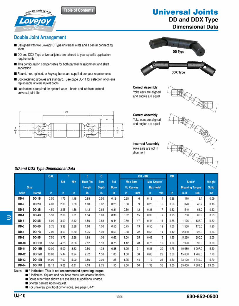
Double Joint Arrangement
■ Designed with two Lovejoy D Type universal joints and a center connecting shaft
■ DD and DDX Type universal joints are tailored to your specific application requirements
■ This configuration compensates for both parallel misalignment and shaft separation
■ Round, hex, splined, or keyway bores are supplied per your requirements
■ Boot retaining grooves are standard. See page UJ-11 for selection of on-site replaceable universal joint boots
■ Lubrication is required for optimal wear – boots and lubricant extend universal joint life
DDX Type
Correct Assembly
Yoke ears are aligned and angles are equal
Correct Assembly
Yoke ears are aligned and angles are equal
DD and DDX Type Dimensional Data
OAL F E C ID1 - ID2 OD
Std Min Main Pin Bore Std Max Bore Max Square/ Static* Weight
Size Height Depth Bore No Keyway Hex Hole3 Breaking Torque Solid
Solid Bored in in in in in in in mm in mm in in-lb Nm lbs
DD-1 DD-1B 3.50 1.75 1.18 0.88 0.56 0.19 0.25 6 0.19 4 0.38 110 12.4 0.09
DD-2 DD-2B 4.00 2.00 1.38 1.00 0.62 0.25 0.38 9 0.25 6 0.50 378 42.7 0.18
DD-3 DD-3B 4.50 2.25 1.56 1.12 0.68 0.31 0.50 12 0.31 7 0.62 540 61.0 0.32
DD-4 DD-4B 5.38 2.68 1.81 1.34 0.88 0.38 0.62 15 0.38 9 0.75 768 86.8 0.55
DD-5 DD-5B 6.00 3.00 2.12 1.50 0.88 0.44 0.69 17 0.44 11 0.88 1,176 133.0 0.82
DD-6 DD-6B 6.75 3.38 2.38 1.68 1.00 0.50 0.75 19 0.50 12 1.00 1,560 176.0 1.20
DD-7 DD-7B 7.00 3.50 2.50 1.75 1.00 0.56 0.88 22 0.56 14 1.12 2,880 325.0 1.56
DD-8 DD-8B 7.50 3.75 2.68 1.88 1.06 0.62 1.00 25 0.62 15 1.25 5,220 590.0 2.05
DD-10 DD-10B 8.50 4.25 3.06 2.12 1.18 0.75 1.12 28 0.75 19 1.50 7,920 895.0 3.30
DD-11 DD-11B 10.00 5.00 3.62 2.50 1.38 0.88 1.25 31 0.81 20 1.75 10,680 1 207.0 5.50
DD-12 DD-12B 10.88 5.44 3.94 2.72 1.50 1.00 1.50 38 0.88 22 2.00 15,600 1 762.0 7.70
DD-13 DD-13B 14.00 7.00 5.00 3.50 2.00 1.25 1.75 44 1.12 28 2.50 33,120 3 742.0 15.70
DD-14 DD-14B 18.12 9.06 6.31 4.53 2.75 1.50 2.00 50 1.38 35 3.00 65,400 7 389.0 29.00
DD Type
Incorrect Assembly
Yoke ears are not in alignment
339
Table of Contents
www.lovejoy-inc.com UJ-11
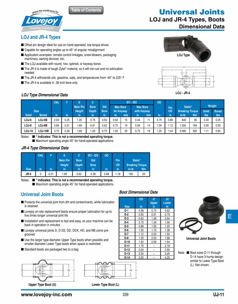
LOJ Type Dimensional Data
OAL F E C ID1 - ID2 OD
PinWeightMain Pin Bore Std Max Bore Max Bore Static*
Size Height Depth Bore No Keyway with Keyway OD Breaking Torque Solid Bored
Solid Bored in in in in in in mm in mm in in in-lb Nm lbs lbs
LOJ-6 LOJ-6B 2.94 0.25 1.35 0.75 0.50 0.62 15 0.44 11 0.75 0.88 840 95 0.30 0.25
LOJ-8 LOJ-8B 3.68 0.31 1.69 0.91 0.62 0.75 19 0.56 14 1.00 1.12 1,500 169 0.65 0.55
LOJ-10 LOJ-10B 3.75 0.38 1.69 1.00 0.75 1.00 25 0.75 19 1.25 1.44 3,480 393 1.11 0.94
Universal JointsLOJ and JR-4 Types, Boots
Dimensional Data
LOJ and JR-4 Types
■ Offset pin design ideal for use on hand operated, low torque drives
■ Capable for operating angles up to 45° of angular misalignment
■ Application examples: remote control linkages, snow blowers, packaging machinery, awning devices, etc.
■ The LOJ available with round, hex, splined, or keyway bores
■ The JR-4 is made of tough Zytel® material, so it will not rust and no lubrication needed
■ The JR-4 withstands oils, gasoline, salts, and temperatures from -40° to 225° F
■ The JR-4 is available in .38 inch bore only
Universal Joint Boots
■ Protects the universal joint from dirt and contaminants, while lubrication is retained
■ Lovejoy on-site replacement boots ensure proper lubrication for up to five times longer universal joint life
■ Installation and replacement is fast and easy, so your machine can be back in operation in minutes
■ Lovejoy universal joints D, D SS, DD, DDX, HD, and NB come pre-grooved
■ Use the larger type diameter Upper Type boots when possible and smaller diameter Lower Type boots when space is restricted
■ Standard boots are packaged two to a bag
LOJ Type
LOJ - JR-4
Notes: n * indicates: This is not a recommended operating torque. n Maximum operating angle 45° for hand-operated applications.
Notes: n * indicates: This is not a recommended operating torque. n Maximum operating angle 45° for hand-operated applications.
JR-4 Type Dimensional Data
OAL F E C ID1 - ID2 OD
Main Pin Bore Std Pin Static*
Height Depth Bore OD Breaking Torque
Size in in in in in in in in-lb Nm
JR-4 3 0.31 1.69 0.62 0.38 0.68 1.18 160 20
Boot Dimensional Data
OD J1 J2Upper Lower
Size in in in
D-1 0.38 0.72 0.62
D-2 0.50 0.91 0.75
D-3 0.62 1.09 0.94
D-4 0.75 1.34 1.06
D-5 0.88 1.50 1.25
D-6 1.00 1.75 1.38
D-7 1.12 2.03 1.50
D-8 1.25 2.03 1.68
D-10 1.50 2.56 1.94
D-11 1.75 – 2.18
D-12 2.00 – 2.59
D-13 2.50 – 3.25
D-14 3.00 – 4.25
Universal Joint Boots
Note: n Boot sizes D-11 through D-14 have 3-hump design similar to Lower Type Boot (L). Not shown.
Upper Type Boot (U) Lower Type Boot (L)
UJ
