junos-es ipsec vpn with pki certificates primer
TRANSCRIPT
Application Note
JUNOS Enhanced Services IPSec VPN with PKI Certificates Primer Version 1.2
Juniper Networks, Inc. 1194 North Mathilda Avenue Sunnyvale, CA 94089 USA 408 745 2000 or 888 JUNIPER www.juniper.net
Richard Kim Technical Support Engineer Advanced JTAC November 2007

2 Copyright © 2007, Juniper Networks, Inc.
Contents Introduction ........................................................................................................................................... 4 Included Platforms and Software Versions ....................................................................................... 4 Glossary of Terms.................................................................................................................................. 4
Overview ................................................................................................................................................ 6 Fundamentals of PKI in JUNOS-ES ................................................................................................. 7 Components ........................................................................................................................................ 7 Certificate Life Cycle Management/Administration...................................................................... 8 Generation of Keys and Cert Request........................................................................................... 8 Cert Enrollment ............................................................................................................................... 9 Usage Within IKE (Identity Usage)............................................................................................... 9 Certificate Validation and Revocation Checking ........................................................................ 9 Certificate Renewal ......................................................................................................................... 9 General Usage..................................................................................................................................... 9 SSL Usage ....................................................................................................................................... 10 IPSec/IKE Usage ............................................................................................................................ 10 What PKI Protocols Are Not Supported in JUNOS-ES ............................................................ 12 Administering PKI in JUNOS-ES ...................................................................................................... 13 Network Diagram (figure 1) ........................................................................................................... 13 Configuration Overview ................................................................................................................ 13 Setting the Device’s Basic Configuration for PKI......................................................................... 14 Configuring Interface IP Addresses............................................................................................ 14 Configuring Default Route........................................................................................................... 14 Setting System Time...................................................................................................................... 14 Setting DNS Configuration .......................................................................................................... 15 Generating the Certificate Request ................................................................................................ 15 Creating a Trusted CA Profile ..................................................................................................... 16 Generating the Cert Request........................................................................................................ 17 Submit Cert Request to the CA and Retrieve Certs ..................................................................... 19 Loading the Local Cert, CA Cert, and CRL .................................................................................. 19 Uploading the Files to Local Storage .......................................................................................... 19 Loading the Local Cert ................................................................................................................. 19 Loading the CA Cert ..................................................................................................................... 20 Loading the CRL............................................................................................................................ 20 Verify All Certs Loaded................................................................................................................ 20 Using the Cert in an IPsec VPN...................................................................................................... 23 Steps to Configure ......................................................................................................................... 23 IPSec VPN Configuration Example for JUNOS-ES ..................................................................... 24 Configuring security zones and assign interfaces to the zones............................................... 24 Configuring host-inbound services for each zone .................................................................... 24 Configuring address book entries for each zone....................................................................... 24 Configuring IKE phase 1 proposal.............................................................................................. 25 Configuring IKE policy................................................................................................................. 25 Configuring IKE gateway............................................................................................................. 26 Configuring IPSec policy.............................................................................................................. 26 Configuring IPSec VPN with IKE gateway and IPSec policy.................................................. 26 Configuring bi-directional tunnel policies for VPN traffic ...................................................... 27 Configuring security policy for Internet traffic ......................................................................... 28 Configuring tcp-mss for TCP traffic across the tunnel............................................................. 28

Copyright © 2007, Juniper Networks, Inc. 3
SSG Configuration Example ........................................................................................................... 29 Verifying Configuration in JUNOS-ES .......................................................................................... 30 Confirming IKE (phase 1) status ................................................................................................. 30 Confirming IPSec (phase 2) status............................................................................................... 31 Checking statistics and errors for an IPSec SA .......................................................................... 32 Testing traffic flow across the VPN ............................................................................................ 32 Troubleshooting Basics ....................................................................................................................... 33 Checking traceoption logs............................................................................................................... 34 Troubleshooting IKE, PKI and IPSec Issues..................................................................................... 34 Enabling IKE traceoptions for phase 1 and phase 2 negotiation issues .................................... 35 Reviewing logs for success/failure messages................................................................................ 36 Common problems related to IKE and PKI .................................................................................. 38 PKI FAQ (Frequently Asked Questions) .......................................................................................... 39 Appendix A: Show Configuration .................................................................................................... 43 Appendix B: Administering Common CAs (Certificate Authorities) .......................................... 47 Microsoft Windows 2000 CA .......................................................................................................... 47 OpenSSL CA ..................................................................................................................................... 52 Appendic C: DoD PKI Usage............................................................................................................. 58 DOD PKI Introduction..................................................................................................................... 58 DOD PKI Setup................................................................................................................................. 59 Appendix D: Simple Certificate Enrollment Protocol (SCEP) ....................................................... 60 Steps to Configure ............................................................................................................................ 60

4 Copyright © 2007, Juniper Networks, Inc.
Introduction JUNOS, the software which runs on J-Series devices, provides not only a powerful operating system, but also a rich IP services toolkit. Through unmatched IP dependability and security, JUNOS ensures an efficient and predictable IP infrastructure. JUNOS Enhanced Services (JUNOS-ES) adds to production-proven JUNOS with greatly enhanced security and VPN capabilities from Juniper Networks Firewall/IPSec VPN product family.
This application note documents many of the PKI (Public Key Infrastructure) concepts, specifications, usage scenarios/decisions, and debugging in JUNOS-ES. It is meant to be more than just a step-by-step guide to configuring and using PKI. Additional details regarding Digital Certificates can be found in the JUNOS System Basics Guide which can be found here:
http://www.juniper.net/techpubs/software/junos/.
The format of the document includes an overview of PKI in JUNOS-ES. The document includes details on defining the architecture for VPN’s based on PKI authentication. Sample configuration scenarios and details on PKI administration are included as well as a troubleshooting guide. The document also contains an FAQ (Frequently Asked Questions) on JUNOS-ES PKI appropriate for use with things like RFP responses. There are also appendices on CA server usage and DOD PKI usage strictly for reference.
This document is not a primer on the general concepts of PKI. There are many sites on the web that can provide documentation on basic PKI concepts. For a starter try this site: http://www.rsasecurity.com/rsalabs for more information on crypto, RSA, and PKI.
Included Platforms and Software Versions This document applies to JUNOS with Enhanced Services version 8.5 or later running on the following hardware platforms…
• J4350
• J6350
• J2320
• J2350
Glossary of Terms This section of the document defines a few terms that are repeatedly used throughout this application note. It in no way encompasses all PKI terminology but does address the bulk of things related to PKI usage in IKE for JUNOS-ES.
CA – Certificate Authority is the server (or set of servers) that sign certificates for VPN gateways and user systems (for client RAS VPN). CA’s also generate CRL’s which are lists of revoked certificates. A CA acts as the trusted third party between two VPN gateways that are authenticating each other using certs.
Certificates (certs) – are the binding of an entity’s identity and public key into a file. This file is digitally signed by the CA so others can validate that entities id and public key if they trust that CA. Certs have a finite life time. In the certificate a start and end time will define that life time.

Copyright © 2007, Juniper Networks, Inc. 5
Outside of that life time the cert is considered invalid. At such time that the life time is expired, a certificate renewal or a new certificate request is required.
CRL – certificate revocation list is something periodically published by the CA and is a list of certs it has signed that are now prematurely invalid.
CDP – CRL Distribution Point (CRL-DP) – is the place to retrieve a CA’s latest CRL. This is usually an LDAP server or HTTP (web) server. So the CDP is normally expressed as an “ldap://host/dir” or “http://host/path” URL.
DN – Distinguished Name is the set of fields and values that uniquely define a certificate and VPN gateway or RAS VPN client identity. This is sometimes called the “Subject” of the certificate. This DN identity can be used as the IKE id. The DN usually has the form:
CN=user name, server DNS name, or most any uniquely identifying string, OU=organizational unit (like “Sales”), O=organization (like “Juniper Networks”), L=locality (like “San Francisco”), S=state (like “CA”), C=country (like “US”).
DNS resolver – the Domain Name Server settings that should be set on the Juniper VPN device to help resolve FQDN names into IP addresses. Many CA’s and certs use host names which need to be resolved into IP addresses.
FQDN – fully qualified domain name is usually the name given to devices on the internet including the DNS-based zone they are in. Examples include www.juniper.net, ocsp.chemistry.nwu.edu, nsgw1.dklein.org, ftp1.whitehouse.gov, and ca2.nit.disa.mil.
IKE – Internet Key Exchange, the ISAKMP/Oakley based process used by two VPN gateways to identify and authenticate each other. In addition, key generation for packet-level authentication (integrity) and encryption (privacy) is handled during IKE. The IKE RFC defines two basic gateway authentication mechanisms: 1) preshared key (like a password) and 2) digital certificates (certs) based on RSA private/public key pairs. This document focuses on the second auth mechanism which is the use of certs.
IKE id – the IKE identity is how two VPN peers will identify each other. The IKE id will have a type and a value. The most common types and example values:
1) IP Address (21.62.2.252);
2) FQDN – fully qualified domain name (vpn1.juniper.net);
3) U-FQDN or email address ([email protected]); and
4) DN – distinguished name (CN=John Doe, OU=eng, O=Juniper, C=US).
IPSec – The protocol used to authenticate, encrypt, and encapsulate IP packets between two VPN/IKE peers thereby creating a tunnel.
NSR – NetScreen-Remote Client is the software for Windows-based PCs or laptops that allow clients to setup a personal VPN to a JUNOS-ES or other IPSec gateway. As opposed to a site-to-site VPN where two VPN devices setup a VPN tunnel between two sites containing many hosts each.
PKI – public key infrastructure is the set of objects that allow the use of digital certificates to be used between two entities (like VPN gateways). This usually includes a CA, RA, certs, CRL’s, CDP’s, and OCSP.

6 Copyright © 2007, Juniper Networks, Inc.
PKCS – the set of documentation defined by RSA Laboratories on various PKI standards:
• PKCS7 – Cryptographic Message Syntax Standard defines how messages are encoded and digitally signed. This includes a certificate itself. Sometimes referred to as a p7 file.
• PKCS10 – Certificate Request Syntax Standard defines how a VPN gateway can form a request for a cert that can be sent to a CA. This request usually contains the VPN gateway’s identity and public key. Sometimes referred to as a p10 file. The CA will digitally sign it with its own private key and return a p7 (cert) file.
• PKCS11 – Cryptographic Token Interface Standard defines how to store certs and private keys on a token card. This is not relevant for JUNOS-ES devices but can be relevant to NSR.
• PKCS12 – Personal Information Exchange Syntax Standard defines how to bundle up an entity’s certificate and public/private key pair into a password protected file. Sometimes referred to as a p12 file. This facilitates moving a user from one machine to another for client VPN’s. This standard is not used by JUNOS-ES devices but can be relevant to NSR.
OCSP – online certificate status protocol is the protocol used for a VPN device to contact a VA (validation authority) to check on the validity of a cert. This is a more scalable alternative to the use of CRL’s and CDP’s.
SCEP – Simple Certificate Enrollment Protocol is used to allow a device to generate a certificate request and automatically submit the request to a CA. Using this protocol requires that both the device and the CA support it. This makes certificate enrollment and re-enrollment easier than manually collecting a PKCS10 from the device and then submitting it to a CA. JUNOS-ES supports SCEP beginning with version 9.0. Refer to Appendix D (page 60) for more details.
U-FQDN – user fully qualified domain name is usually the email address given to users on the internet or corporate network. Examples include [email protected], [email protected], and [email protected].
Overview This section of the document addresses the fundamentals of PKI in JUNOS-ES such as the various components (private/public keys, certs, CA’s, and revocation checking options), certificate life cycle management, and how to use the certs in SSL (informational purposes for future support) and IPSec/IKE. Juniper uses public/private keys within four areas of JUNOS-ES:
• SSH/SCP (for secure CLI-based administration);
• SSL (for secure Web-based administration and https-based webauth for user authentication); and
• IKE (for IPSec VPN tunnels).
Currently for JUNOS-ES, only IKE uses PKI certificates for public key validation and identity binding with SSL support possible in a future release. SSH/SCP are used exclusively for system administration and rely on the use of out-of-band “fingerprints” for public key identity binding and validation. Details on SSH are out of the scope of this document. The bulk of this document will focus on the administration of PKI and its use IKE. A brief section on SSL is included as well for reference.

Copyright © 2007, Juniper Networks, Inc. 7
Fundamentals of PKI in JUNOS-ES This section describes the basic elements of PKI in JUNOS-ES including components of the PKI, certificate life cycle management, and usage within IKE.
Components There are three main components to administer PKI within JUNOS-ES:
• CA certificates and authority configuration;
• Local certificates including the devices identity (e.g., IKE id type and value) and private/public keys; and
• Certificate validation via a CRL.
JUNOS-ES also has three specific types of PKI objects:
• Private/public key pair;
• Certificate – three different kinds: 1. Local cert; 2. CA cert; 3. Pending cert;
• CRL (certificate revocation lists).
The local certificate contains the Juniper device’s public key and identity information. A certificate is considered a local cert if the Juniper device possesses the associated private key and that cert was generated based on a cert request from that Juniper device. A pending cert is when a key pair and identity information have been generated into a PKCS10 cert request and manually sent to a CA. Automatic sending of cert requests via SCEP is not supported in JUNOS-ES until version 9.0R1 (See Appendix D for more details on SCEP). While the Juniper device waits for the cert from the CA, the existing object (key pair plus cert request) is tagged as a certificate request or pending cert. Once the cert is issued by the CA and loaded into the Juniper device, the pending cert is replaced by the newly generated local cert. All other certs loaded into the device are considered CA certs.
JUNOS-ES can support multiple local certs. This is dependent on the device size. See the FAQ below for details. The use of multiple local certs is generally used where a Juniper device may have VPN’s in more than one administrative domain.
All PKI objects are stored in a separate part of persistent memory than the JUNOS-ES image and the system’s general configuration. Each PKI object has a unique name or certificate-id given to it from birth and maintains that id until deletion. The certificate-id can be seen with ʺshow security pki local-certificateʺ command.
In general, a certificate cannot be copied off of a device. The private key on a device must be generated on that device. And the private key can never be viewed or saved from that device. So PKCS12 files (which contain a cert with the public key and the associated private key) are not supported on JUNOS-ES devices. CA certs are generally used to validate certificates received by the IKE peer. If the cert is valid then it will be checked against the CRL to see if the cert has been revoked. In addition to the CA cert[s] themselves, there is a CA profile configuration for each CA cert. This configuration object stores information related to this particular CA and includes:
• CA Identity which is typically the domain name of the CA;

8 Copyright © 2007, Juniper Networks, Inc.
• Email address to allow for cert requests to be sent directly to the CA; and
• Revocation settings which include: 1. Revocation check enable/disable; 2. Disable revocation check if failed to download CRL; 3. Location of CDP (manual URL setting); and 4. CRL refresh interval.
The possible PKI objects and their average sizes are:
• Private/public key pair (1 KB)
• Local Certificate (2 KB)
• CA Certificate (2KB)
• CA authority configuration (500 Bytes)
• CRL (average size is highly variable depending on how many certs have been revoked by that particular CA: 300 bytes up to 2MB+).
Assuming an average CRL of 10KB a JUNOS-ES device with one local cert, one CA cert and auth config, and the CRL from that cert has the following flash memory requirements:
15.5 KB = 2KB (local cert) + 1 (key pair) + 2 (CA cert) + 0.5 (CA auth conf) + 10 (CRL)
For certificate chains you would need to add additional CA certs, additional CA profile configs, and additional CRL’s for each CA in the hierarchy or cross-certified chain. In general the higher-end JUNOS-ES devices, with more persistent memory, can accommodate several local certs and CA chains. However the smaller devices, with more limited storage capacity, can quickly have their portion of persistent memory allocated for PKI objects fill up. It’s typically recommended that the lower-end devices use only one local cert/key pair, one CA (or one chain of CA’s), and one CRL.
Certificate Life Cycle Management/Administration The general life cycle for certificates are as below:
1. Generation of public/private keys, identity information, and cert request;
2. Enrollment (request and retrieval);
3. Usage within IKE;
4. Certificate validation and revocation checks;
5. Renewal.
Additional details regarding the above life cycle can be found below.
Generation of Keys and Cert Request
As mentioned previously, the private key on a device must be generated on that device. And the private key can never be viewed or saved from that device. The user identity and private key forms the basis of the certificate request and will continue to be used with the local cert after enrollment. Therefore it is important to match the certificate-id of the keys generated with the proper cert request and eventually the local cert. Also as mentioned earlier, the cert request will be in the PKCS10 format and must be sent to the CA either via email or some sort of web-based front-end site.

Copyright © 2007, Juniper Networks, Inc. 9
Cert Enrollment
JUNOS-ES version 8.5 only supports the manual certificate request and retrieval process which would include generation of a PKCS10 request, submittal to the CA, retrieval of the signed cert, and manually loading the cert into the JUNOS-ES device as the local cert. SCEP, which can be administratively easier, is supported beginning with 9.0 (refer to Appendix D for SCEP details).
Usage Within IKE (Identity Usage)
During IKE phase 1 setup using certificates, a cert is used to identify the peer. The identity can be any of the below:
• IP address;
• FQDN (domain name);
• U-FQDN (email address); or
• DN (Distinguished Name).
Most VPN administrators are used to using IP address or FQDN for a VPN gateway’s identity type and an email address (U-FQDN) for an NSR client VPN laptop/user’s identity type. These IKE ids, if used, must be put into the SubjectAlternativeName (a v3 extension) field of the cert. IP addresses should generally be avoided because if the IP address of the VPN peer changes then you will have to issue a new certificate with the new IP address and revoke the old one. By using a non-IP IKE id type then you need not worry about having to change the certificate if the device’s IP address should change. If the CA doesn’t support the signing of certificates with a SubjectAlternativeName field then you will have to use the DN as the IKE id on the JUNOS-ES device or NSR configurations. Note that during the certificate request process, one of either IP address, domain name or email address must be specified as the IKE id.
Certificate Validation and Revocation Checking
Revocation checking uses CRL lookup method in JUNOS-ES. The CRL can either be manually loaded in the JUNOS-ES device or via automatic retrieval of CRL online from the CDP, on demand via LDAP or HTTP. Both DER and PEM formats for CRL are supported. OCSP is typically a much more scalable system than the use of CRL’s and CDP. However OCSP is currently not supported in JUNOS-ES and many CA’s also do not support an OCSP interface.
Certificate Renewal
The renewal of certificates is much the same as initial certificate enrollment except you are just replacing an old certificate (about to expire) on the VPN device with a new certificate. As with the initial certificate request, only manual renewal is supported. SCEP can be used to re-enroll local certificates automatically before they expire. Refer to Appendix D for more details.
General Usage Currently IPSec/IKE is the only JUNOS-ES feature that uses certificates for public key validation and identity binding. However support for SSL may be possible in a future JUNOS-ES release. Cert usage related to SSL is very straightforward. Thus SSL support will be discussed in this application note for informational purposes only.

10 Copyright © 2007, Juniper Networks, Inc.
SSL Usage
Certificates for SSL are much simplier to deal with than with IKE. IKE implementation is typically bi-directional authentication using certificates. So each VPN device sends their cert to the other. Each IPSec device then needs to validate the other device’s cert using the CA cert (or chain of CA certs if a hierarchy of CA’s are used) and checking the cert via a CRL.
In SSL, the whole negotiation is a lot more one-sided and far simplier. For SSL, the security device is acting as an SSL-server whereas the administrator’s web browser (or for webauth, the user’s web browser) is the SSL client. In these cases, the security device is only sending its cert to the web browser for identification so the Web Browser can begin a secured SSL session. The security device will not require a user-based SSL cert from the web browser. It will simply authenticate the user or administrator via a login and password secured with the SSL encryption. Thus, for SSL, a security device does not need CA CRL’s loaded.
IPSec/IKE Usage
IKE is bi-directionally authenticated using certificates. So each VPN device sends their cert to the other. Each VPN device then needs to validate the other device’s cert using the CA cert (or chain of CA certs if a hierarchy of CA’s are used) and then check the other’s cert via a CRL to see if it has been revoked.
Process to setup PKI elements
The minimum PKI elements needed to use certificate-based authentication in JUNOS-ES is a local cert, CA cert, and the CA’s CRL. These can be manually loaded. The manual process is:
1. Set basic device configuration items needed by PKI: a) Set the clock, date, time zone, and daylight savings settings to be accurate; b) Set DNS to be able to resolve host names that may be used in certs and for CDP’s; c) Set NTP to maintain accurate clock since certs have lifetimes based on specific date and time.
2. Create a ca-profile to be used for the certificate request and enrollment process.
3. Generate the cert request (p10 file) and save it to a local file system (or send via email).
4. Submit the p10 file to the CA – this is usually done via a web server that front-ends the CA. Although openSSL’s CA is all command-line driven.
5. Retrieve the CA’s own cert (via the CA’s web server front-end interface).
6. Retrieve the JUNOS-ES device’s new local cert after the CA has vetted it (usually via the CA’s web server front-end interface).
7. Retrieve the CA’s CRL (usually via a pre-specified URL to the CA’s web server).
8. Load the CA cert, local cert, and CRL onto the JUNOS-ES device.
9. Define the IKE policy and gateway to use RSA-Signature authentication method (as opposed to pre-shared keys) and the local and CA certs.
The drawback to manually loaded certs and CRL’s is that it can be staff intensive especially maintaining an up-to-date CRL on all the boxes. To ease CRL administration it’s best to define a CDP that the JUNOS-ES device can contact to automatically retrieve the latest CRL. Most CA’s have the CDP defined in the CA cert itself which the JUNOS-ES device will try to use automatically. You can also define the CDP in the ca-profile configuration.
Copyright © 2007, Juniper Networks, Inc. 11
The step-by-step detailed procedures for all these processes can be found later in this document and in the JUNOS-ES Configuration Guides downloadable here:
http://www.juniper.net/techpubs/software/junos/
Choosing the IKE identity to use in the VPN and the cert
With JUNOS-ES there are four possible IKE id types that can be used for one VPN gateway to identify the other (When doing pre-shared keys, we can only do 1, 2, or 3):
1. IP Address (e.g., 2.2.2.2);
2. FQDN or fully qualified domain name (e.g., vpn1.juniper.net);
3. U-FQDN or email address (e.g., [email protected]); or
4. DN or distinguished name (e.g., CN=John Doe, OU=sales, O=Juniper Networks, C=US).
If you use any of the first three (IP, domain name or email) then this must be defined in the SubjectAlternativeName extension field of the cert. These then have to match the JUNOS-ES peer configuration in the ʺsecurity ike gateway <gateway-name>” hierarchy. One of either 1, 2 or 3 is mandatory when generating a certificate request.
If your certificates donʹt have SubjectAlternativeName fields then you have to use DN for the IKE id. You do this by defining distinguished-name in dynamic IKE configuration. For distinguished-name you can specify container (DN must match exactly) or wildcard (only a portion of the DN needs to match). Below are more details regarding the difference between container and wildcard methods.
• If the “container” keyword is used then all the DN identity fields must exactly match the values in the cert. In addition, the ordering of the values in both the remote cert received and the gateway definition must match.
• If the “wildcard” keyword is used then the DN values specified must match the DN in the cert received. However, any unspecified fields can contain anything in the cert. The ordering of the identity fields in the remote cert received and in the gateway definition can be different. The JUNOS-ES device will only parse out and compare the DN fields defined.
Also, if the certificate uses multiple fields of the same type (e.g.,OU=sales,OU=engr, OU=central) then you have to use the “container” method and DN definition must be defined exactly as it is received by the remote peer.
Cert validation within the IKE phase 1 setup
During the IKE exchange, when the two VPN peers are establishing a tunnel, each VPN device will receive a cert from the other IKE peer. The JUNOS-ES device will:
1. Pull the IKE identity offered in IKE phase 1 from the peer and do a search through the configuration to find the matching IKE gateway definition;
2. Validate the cert it has received making sure it has not been tampered with. It will do this by validating the digital signature on the remote’s cert using the public key in the CA’s cert;
3. Validate the current time is after the cert’s “Valid from” but before its “Valid to” fields;
4. Validate that the cert contains the identity for that remote peer;

12 Copyright © 2007, Juniper Networks, Inc.
5. Do the revocation check (unless revocation check is disabled) on the cert by checking to make sure the cert’s serial number is not in the CA’s CRL. This may cause the JUNOS-ES device to automatically retrieve a new CRL from the CDP;
6. If all the cert checks pass then IKE will continue with the tunnel setup.
Unless explicitly disabled in configuration, CRL’s are checked whenever the JUNOS-ES device receives a certificate for a remote VPN gateway. If the CRL for the signing CA is not manually loaded, it will try to:
1. Load the CRL from the CDP defined in the cert. JUNOS-ES devices support HTTP and LDAP for CDP’s;
2. If the CDP is not available in the cert then the JUNOS-ES device will check for a CDP setting in the CA profile; or
3. The JUNOS-ES device will use the globally (or default) CDP setting if one has been configured.
When verifying a certificate, a certificate chain is built. It is built from the remote’s local cert, the optional certificate chain sent from the IKE peer, and CA certificates stored locally. Any CA certificates loaded from local store during boot are considered “trusted”. JUNOS-ES supports certificate path validation upward through up to 7 levels of CA authorities in the hierarchy.
JUNOS-ES currently only supports “partial” cert path validation. Unlike “full” cert path validation, “partial” does not require that the last certificate in the certificate chain be a root CA cert (a self-signed CA). Thus with ʺpartialʺ then the last cert may be a non-root CA cert. However, the last certificate in the validation chain must come from local storage.
What PKI Protocols Are Not Supported in JUNOS-ES
There are a couple of protocols used in PKI not supported by JUNOS-ES. These protocols are primarily alternative forms of management protocols for communication between CA’s and entities that use certs. These include:
1. CMC – Certificate Management of Messages over CMS defined in RFC 2797.
2. CMP – Certificate Management Protocol defined in RFC 2510.
3. XKMS – XML Key Management Specifications defined here: http://www.w3.org/TR/xkms/
CMC is endorsed by Microsoft and VeriSign but there are limited products shipping that support it.
CMP is endorsed by Entrust, Baltimore, SSH, RSA, and OpenSSL. It generally works, has limited deployment, and some interoperability has been demonstrated between vendors.
XKMS is relatively early on in its development and seem promising. However, Juniper does not support this at this time.
The battle for Certificate management seems to be between CMC and CMP. The existence of the two standards to accomplish the same thing has created a “road block” in the PKI industry. A VPN vendor would have to implement both to work with all major PKI vendors which is not feasible given the percentage of VPN’s currently using PKI. And the VPN’s currently using PKI are getting along with SCEP and CDP/OCSP.
Copyright © 2007, Juniper Networks, Inc. 13
Administering PKI in JUNOS-ES This section of the document discusses more details related to the administration and use of PKI in JUNOS-ES. Detailed procedures for administration of PKI can be found in the JUNOS-ES Configuration Guides for VPN’s.
http://www.juniper.net/techpubs/software/junos/
The reader should consult those documents when trying to setup PKI and use it with IPSec/IKE VPNs. This section will try to augment the Configuration Guide with other details using examples. More details regarding using a CA from PKI vendors like Microsoft and OpenSSL can be found in Appendix B at the end of this document. The main sub-sections in this section of the document are:
• IPSec VPN – specifics of PKI related to IKE and configuration;
• Verifying PKI configurations and operation;
• Troubleshooting PKI and IKE in JUNOS-ES.
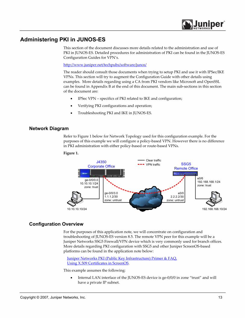
Network Diagram Refer to Figure 1 below for Network Topology used for this configuration example. For the purposes of this example we will configure a policy-based VPN. However there is no difference in PKI administration with either policy-based or route-based VPNs.
Figure 1.
Configuration Overview For the purposes of this application note, we will concentrate on configuration and troubleshooting of JUNOS-ES version 8.5. The remote VPN peer for this example will be a Juniper Networks SSG5 Firewall/VPN device which is very commonly used for branch offices. More details regarding PKI configuration with SSG5 and other Juniper ScreenOS-based platforms can be found in the application note below:
Juniper Networks PKI (Public Key Infrastructure) Primer & FAQ, Using X.509 Certificates in ScreenOS.
This example assumes the following:
• Internal LAN interface of the JUNOS-ES device is ge-0/0/0 in zone “trust” and will have a private IP subnet.
J6350TX /R X 0 /0 LI NK TX/R X 0/1 LINK TX/R X 0/ 2 LINK TX/ RX 0/3 LINK
1 0/ 100/1 00 0 CONSOLE A UX
0
1
USB
SLOT NUMBER
123
456
ST ATUSPOWER
ALARM HA POWER RESETCONFIG
SSG 5
AUX CONSOLE 0/0
TX/R X LI NK
0/1
TX/ RX LIN K
0/2
TX /R X LI NK
0/3
TX/RX LIN K
0/4
TX/RX LINK
0/5
TX/RX LI NK
0/6
TX/RX LINK
10/1 00
POWER
STATUS
802.11a
WLAN
b /g
J4350Corporate Office SSG5
Remote Office
ge-0/0/3.01.1.1.2/30zone: untrust
e0/02.2.2.2/30
zone: untrust
e0/6192.168.168.1/24zone: trust
192.168.168.10/24
ge-0/0/0.010.10.10.1/24
zone: trust
10.10.10.10/24
Clear trafficVPN traffic
14 Copyright © 2007, Juniper Networks, Inc.
• Internet interface of the JUNOS-ES device is ge-0/0/3 in zone “untrust” and will have a public IP.
• All traffic between the local and remote LANs are to be permitted, and traffic may be initiated from either side.
• The SSG5 has already been preconfigured with the correct information from this example and local-cert, CA-cert and CRL are already loaded and ready to use.
• The SSG5 is configured to use FQDN as ssg5.juniper.net as the IKE id.
• PKI certificates with 1024 bit keys will be used for the IKE negotiations on both sides.
• The CA is a standalone CA at domain labdomain.com for both VPN peers.
Setting the Device’s Basic Configuration for PKI
Configuring Interface IP Addresses
Referring to the above network diagram (figure 1), configure the IP addresses for ge-0/0/0.0 and ge-0/0/3.0. In this example unit 0 and family inet (IPv4) are used.
Syntax (configure mode): set interfaces <interface-name> unit <unit-value> family inet address <ip-prefix>
Example: root@CORPORATE> configure
Entering configuration mode
[edit]
root@CORPORATE# set interfaces ge-0/0/0 unit 0 family inet address 10.10.10.1/24
[edit]
root@CORPORATE# set interfaces ge-0/0/3 unit 0 family inet address 1.1.1.2/30
Configuring Default Route
Configure the default route to the Internet next-hop. Optionally you can use a dynamic routing protocol such as OSPF instead but that is beyond the scope of this application note. When processing the first packet of a new session, the JUNOS-ES device will first perform a route lookup. The below static route which happens to be the default route will dictate which zone the VPN traffic needs to egress. In this example the VPN traffic will ingress on interface ge-0/0/0.0 with the next-hop of 1.1.1.1. Thus the traffic will egress out interface ge-0/0/3.0 interface. Any tunnel policy will need to take into account ingress and egress interfaces.
Syntax (configure mode): set routing-options static route <ip-prefix> next-hop <next-hop-ip>
Example: [edit]
root@CORPORATE# set routing-options static route 0.0.0.0/0 next-hop 1.1.1.1
Setting System Time
An accurate clock is very important for all devices using certs. The best method is to use NTP for keeping clocks accurate. The following example will enable NTP, set the NTP server at 130.126.24.24, and will set the timezone to US Pacific Daylight Time-zone (e.g., Los Angeles).

Copyright © 2007, Juniper Networks, Inc. 15
Syntax (configure mode): set system time-zone (GMThour-offset | time-zone)
Syntax (operational mode): set date ntp (ntp-server-ip | ntp-server-domainname) source-address <ip-prefix>
Example: [edit]
root@CORPORATE# set system time-zone PST8PDT
[edit]
root@CORPORATE# commit and-quit
commit complete
Exiting configuration mode
root@CORPORATE> set date ntp 130.126.24.24
1 Nov 17:52:52 ntpdate[5204]: step time server 130.126.24.24 offset -0.220645 sec
Once the configuration is commited, verify clock settings with the command below (system current time highlighted in red):
root@CORPORATE> show system uptime
Current time: 2007-11-01 17:57:09 PDT
System booted: 2007-11-01 14:36:38 PDT (03:20:31 ago)
Protocols started: 2007-11-01 14:37:30 PDT (03:19:39 ago)
Last configured: 2007-11-01 17:52:32 PDT (00:04:37 ago) by root
5:57PM up 3:21, 4 users, load averages: 0.00, 0.00, 0.00
Setting DNS Configuration
Many CA’s use host names (i.e., FQDN) to specify various elements of the PKI. For example, the CDP usually is specified using a URL containing a FQDN. For this reason, DNS resolver on the JUNOS-ES device should be configured. Below is an example of DNS resolver configuration.
Syntax (configure mode): set system name-server <dns-server-ip>
Example: root@CORPORATE> configure
Entering configuration mode
[edit]
root@CORPORATE# set system name-server 4.2.2.1
[edit]
root@CORPORATE# set system name-server 4.2.2.2
[edit]
root@CORPORATE# commit and-quit
commit complete
Exiting configuration mode
Generating the Certificate Request There are two basic steps for the certificate request process. The first step is to create a CA profile to specify the CA settings. The second step is to generate the PKCS10 cert request. The PKCS10 cert request process involves first generating a public/private key pair and then generating the cert request itself using the key pair.
16 Copyright © 2007, Juniper Networks, Inc.
Creating a Trusted CA Profile
The CA profile configuration specifies the information specific to a certificate authority. There can be multiple such profiles present in the system. For example, we may have one such profile for Verisign and one for Entrust. Each profile is associated with a CA certificate. If a new or renewed CA certificate needs to be loaded without removing the older CA certificate, a new profile would be needed. This profile can also be used for online fetching of the CRL.
Syntax (configure mode): set security pki ca-profile <ca-profile-name> ca-identity <ca-identity>
set security pki ca-profile <ca-profile-name> revocation-check crl
refresh <number-hours> url <url-string>;
Example: root@CORPORATE> configure
Entering configuration mode
[edit]
root@CORPORATE# set security pki ca-profile ms-ca ca-identity labdomain.com
[edit]
root@CORPORATE# set security pki ca-profile ms-ca revocation-check crl refresh-
interval 48
[edit]
root@CORPORATE# set security pki ca-profile ms-ca revocation-check crl url
http://labsrv1.labdomain.com/CertEnroll/LABDOMAIN.crl
[edit]
root@CORPORATE# set security pki ca-profile ms-ca administrator email-address
[edit]
root@CORPORATE# commit and-quit
commit complete
Exiting configuration mode
The mandatory configuration includes the CA profile name (ms-ca for this example) and CA identity (labdomain.com). The CA profile name can be any value, while the CA identity is typically the CA domain name. All other CA profile settings are not mandatory.
Revocation-check specifies how certificate revocation will be checked. If disable flag is configured, then revocation check would be disabled. Within the revocation-check hierarchy, the crl section defines how CRL is handled:
• Refresh interval – allows the user to specify frequency to update CRL, Default: next-update time in CRL or 1 week if no next-update;
• Url – location to retrieve CRL, could be HTTP or LDAP, Default: empty (use CDP information embedded in CA cert).
The refresh interval is configured with units of 1 hour. Thus refresh-interval 48 means the CRL will be refreshed every 48 hours or 2 days. The URL configuration would override the CDP information embedded within the CA cert. The URL could also contain just the server-name/port information, (e.g., ʺldap://<ip-or-fqdn>:<port>ʺ). If port number is missing, HTTP will use port 80 or LDAP will use port 443. Currently only one URL is supported, there is no provision to configure a backup URL.
The certificate request can be sent to the CA through an out-of-band method. Or it can be sent to a CA administrator directly via an email address. This is the administrator email address configuration in the ca-profile-name hierarchy. In this latter case, the JUNOS-ES device will:
Copyright © 2007, Juniper Networks, Inc. 17
• compose the email from the certificate request file;
• forward the email to the address configured; and
• report email status to the device admin.
Thus a PKCS10 cert request would be generated and stored on the JUNOS-ES device as a pending cert or certificate request. But also an email would be generated and sent to the administrator of the CA (in the above example that would be [email protected]).
A special default (fallback) profile can also be created for intermediate CA’s not pre-installed in device. The values in this default profile will be used when there is no specific CA profile. In case of CDP, the first CDP found will be used in following order:
1. per CA profile;
2. CDP embedded in CA certificate;
3. default CA profile.
However, specific CA profiles are recommended. A default profile is not required.
Generating the Cert Request
Generating public/private key pair
Once the CA profile is configured, the next step is to generate a key-pair on the JUNOS-ES device. The following command is used to generate the private and public key-pair.
Syntax (operational mode): request security pki generate-key-pair certificate-id <id-name> size <key-size>
Currently JUNOS-ES supports only the RSA algorithm. DSA is not supported. A unique ID called certificate-id is used to name the generated key-pair. This ID is then used in certificate enrollment and request commands to get the right key-pair. The generated key-pair is saved in the certificate-store in a file with same name as the certificate-id. The size can be 512, 1024 or 2048 bits.
Example: root@CORPORATE> request security pki generate-key-pair certificate-id ms-cert
size 1024
Generated key pair ms-cert, key size 1024 bits
Generating cert request from the key pair
The next step is to generate the PKCS10 cert request to be sent to the CA. The following command is used to generate the certificate request and save it in a file location as specified. Also, it keeps a local copy of the certificate request in the local certificate store. If the administrator re-issues this command, the certificate request is generated all over again.
Syntax (operational mode): request security pki generate-certificate-request certificate-id <id-name>
subject “<subject-name>” (domain-name <domain-name> | ip-address <device-ip> |
email <email-id>) filename <filename>
The certificate-id should match the same id-name used during the generation of the key pair. This will ensure that the proper key pair is used for the cert request and ultimately the local cert. The subject name is specified in the distinguished name format thus an administrator

18 Copyright © 2007, Juniper Networks, Inc.
should enter the components which include common name, department, company name, locality (usually city), state, country name, phone and domain component in the format:
• common name, CN=
• department, OU=
• company name, O=
• locality, L=
• state, ST=
• country, C=
• phone, CN=
• domain component, DC=
Not all subject-name components are required and multiples of each type are allowed. One of either domain-name, ip-address or email is mandatory. This defines the IKE id type and will need to be configured to match in the IKE gateway profile described later in this document.
The filename defines the name of the file which will contain the PKCS10 cert request which can then be offloaded from the JUNOS-ES device and sent to the CA for enrollment. However the PKCS10 cert request will also print to the CLI window and can be copied and pasted to a web front-end for the CA server or to an email. Thus the filename is not mandatory as the certificate request could still be displayed with command: “show security pki certificate-request certificate-id <id-name>”.
Below is an example of a certificate request and the command output.
Example: root@CORPORATE> request security pki generate-certificate-request certificate-id
ms-cert subject "CN=john doe,CN=1.1.1.2,OU=sales,O=Juniper Networks, L=Sunnyvale,ST=CA,C=US" email [email protected] filename ms-cert-req
Generated certificate request
-----BEGIN CERTIFICATE REQUEST-----
MIIB3DCCAUUCAQAwbDERMA8GA1UEAxMIam9obiBkb2UxDjAMBgNVBAsTBXNhbGVz
MRkwFwYDVQQKExBKdW5pcGVyIE5ldHdvcmtzMRIwEAYDVQQHEwlTdW5ueXZhbGUx
CzAJBgNVBAgTAkNBMQswCQYDVQQGEwJVUzCBnzANBgkqhkiG9w0BAQEFAAOBjQAw
gYkCgYEA5EG6sgG/CTFzX6KC/hz6Czal0BxakUxfGxF7UWYWHaWFFYLqo6vXNO8r
OS5Yak7rWANAsMob3E2X/1adlQIRi4QFTjkBqGI+MTEDGnqFsJBqrB6oyqGtdcSU
u0qUivMvgKQVCx8hpx99J3EBTurfWL1pCNlBmZggNogb6MbwES0CAwEAAaAwMC4G
CSqGSIb3DQEJDjEhMB8wHQYDVR0RBBYwFIESInVzZXJAanVuaXBlci5uZXQiMA0G
CSqGSIb3DQEBBQUAA4GBAI6GhBaCsXk6/1lE2e5AakFFDhY7oqzHhgd1yMjiSUMV
djmf9JbDz2gM2UKpI+yKgtUjyCK/lV2ui57hpZMvnhAW4AmgwkOJg6mpR5rsxdLr
4/HHSHuEGOF17RHO6x0YwJ+KE1rYDRWj3Dtz447ynaLxcDF7buwd4IrMcRJJI9ws
-----END CERTIFICATE REQUEST-----
Fingerprint:
47:b0:e1:4c:be:52:f7:90:c1:56:13:4e:35:52:d8:8a:50:06:e6:c8 (sha1)
a9:a1:cd:f3:0d:06:21:f5:31:b0:6b:a8:65:1b:a9:87 (md5)
The PKCS10 certificate request (highlighted in RED) starts with and includes the “BEGIN CERTIFICATE REQUEST” line and ends with and includes the “END CERTIFICATE REQUEST” line. This portion can be copied and pasted to your CA for enrollment. Optionally, you can also offload the “ms-cert-req” file and send that to your CA.
Copyright © 2007, Juniper Networks, Inc. 19
Submit Cert Request to the CA and Retrieve Certs At this point, the JUNOS-ES device Administrator needs to submit the cert request to their CA. Once the CA administrator has vetted the cert request, thereby generating a new cert for the JUNOS-ES device, the JUNOS-ES device admin will need to retrieve it along with the CA cert and CRL.
The process of retrieving the CA cert, the JUNOS-ES device’s new local cert, and CRL from the Certificate Authority are dependent on the CA configuration and software vendor in use. Later in this application note are two sections showing how to do this with a Microsoft CA available on Win2000 Advanced Server and with OpenSSL.
JUNOS-ES supports these CA vendors:
• Entrust
• Verisign
• Microsoft
Other CA software and/or services (like OpenSSL) should work, but have not been verified by Juniper. However, JUNOS-ES likely will support other vendors as long as they conform to X.509 certificate standards.Generating the Cert Request
Loading the Local Cert, CA Cert, and CRL Once the local cert, CA cert and CRL are retrieved from the CA they can be loaded into the JUNOS-ES device via the CLI. You can upload the individual files onto the JUNOS-ES local storage via FTP.
Uploading the Files to Local Storage
Assuming the new local cert is named certnew.cer, the CA cert is named CA-certnew.cer, and the CRL is named certcrl.crl, be sure to place the individual files on a reachable FTP server. Upload the individual files onto the JUNOS-ES device local storage using the command below.
Syntax (operational mode): file copy <source-file-path/filename> <local-file-name>
Example: root@CORPORATE> file copy ftp://10.10.10.10/certnew.cer certnew.cer
/var/tmp//...transferring.file.........crYdEC/100% of 1459 B 5864 kBps
root@CORPORATE> file copy ftp:// 10.10.10.10/CA-certnew.cer CA-certnew.cer /var/tmp//...transferring.file.........UKXUWu/100% of 1049 B 3607 kBps
root@CORPORATE> file copy ftp:// 10.10.10.10/certcrl.crl certcrl.crl /var/tmp//...transferring.file.........wpqnpA/100% of 401 B 1611 kBps
You can verify that all files have been uploaded with command: “file list”.
Loading the Local Cert
This command is used to load the certificate into local store from the specified external file. It needs to specify the certificate-id in order to keep the proper linkage with the private/public key-pair. This will also load the certificate into RAM cache storage of the PKI module. The
20 Copyright © 2007, Juniper Networks, Inc.
associated private key will also be checked and signing operation verified.
Syntax (operational mode): request security pki local-certificate load certificate-id <certificate-id>
filename <path/filename>
Example: root@CORPORATE> request security pki local-certificate load certificate-id ms-cert
filename certnew.cer
Local certificate loaded successfully
Loading the CA Cert
Load the CA certificate from the specified external file with the command below. The CA profile will need to be specified to link the CA cert to the profile configured.
Syntax (operational mode): request security pki ca-certificate load ca-profile <ca-profile-name>
filename <path/filename>
Example: root@CORPORATE> request security pki ca-certificate load ca-profile ms-ca filename
CA-certnew.cer
Fingerprint:
1b:02:cc:cb:0f:d3:14:39:51:aa:0f:ff:52:d3:38:94:b7:11:86:30 (sha1)
90:60:53:c0:74:99:f5:da:53:d0:a0:f3:b0:23:ca:a3 (md5)
Do you want to load this CA certificate ? [yes,no] (no) yes
CA certificate for profile ms-ca loaded successfully
Loading the CRL
This command will load the CRL into the local store. Maximum size is 5MB. As with the CA cert, the CA profile must be specified.
Syntax (operational mode): request security pki crl load ca-profile <ca-profile-name> filename
<path/filename>
Example: root@CORPORATE> request security pki crl load ca-profile ms-ca filename
certcrl.crl
CRL for CA profile ms-ca loaded successfully
Verify All Certs Loaded
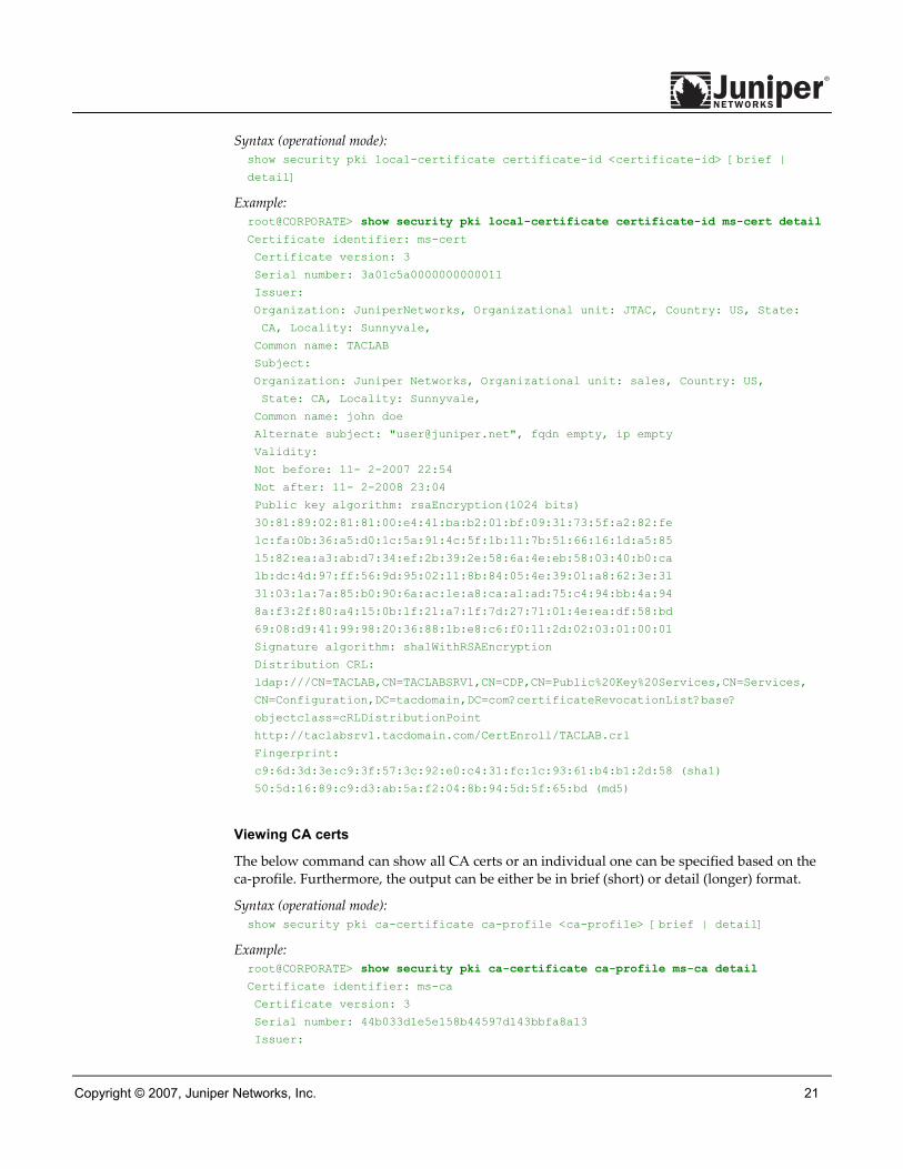
The commands to show the certs are as below. These commands will show the certificates present in the local store. There is also an option to show the certificate request generated in the PKCS-10 format.
Viewing local certs
The below command can show all local certs or an individual one can be specified based on the certificate-id. Furthermore, the output can be either be in brief (short) or detail (longer) format.
Copyright © 2007, Juniper Networks, Inc. 21
Syntax (operational mode): show security pki local-certificate certificate-id <certificate-id> [brief |
detail]
Example: root@CORPORATE> show security pki local-certificate certificate-id ms-cert detail
Certificate identifier: ms-cert
Certificate version: 3
Serial number: 3a01c5a0000000000011
Issuer:
Organization: JuniperNetworks, Organizational unit: JTAC, Country: US, State:
CA, Locality: Sunnyvale,
Common name: TACLAB
Subject:
Organization: Juniper Networks, Organizational unit: sales, Country: US,
State: CA, Locality: Sunnyvale,
Common name: john doe
Alternate subject: "[email protected]", fqdn empty, ip empty
Validity:
Not before: 11- 2-2007 22:54
Not after: 11- 2-2008 23:04
Public key algorithm: rsaEncryption(1024 bits)
30:81:89:02:81:81:00:e4:41:ba:b2:01:bf:09:31:73:5f:a2:82:fe
1c:fa:0b:36:a5:d0:1c:5a:91:4c:5f:1b:11:7b:51:66:16:1d:a5:85
15:82:ea:a3:ab:d7:34:ef:2b:39:2e:58:6a:4e:eb:58:03:40:b0:ca
1b:dc:4d:97:ff:56:9d:95:02:11:8b:84:05:4e:39:01:a8:62:3e:31
31:03:1a:7a:85:b0:90:6a:ac:1e:a8:ca:a1:ad:75:c4:94:bb:4a:94
8a:f3:2f:80:a4:15:0b:1f:21:a7:1f:7d:27:71:01:4e:ea:df:58:bd
69:08:d9:41:99:98:20:36:88:1b:e8:c6:f0:11:2d:02:03:01:00:01
Signature algorithm: sha1WithRSAEncryption
Distribution CRL:
ldap:///CN=TACLAB,CN=TACLABSRV1,CN=CDP,CN=Public%20Key%20Services,CN=Services,
CN=Configuration,DC=tacdomain,DC=com?certificateRevocationList?base?
objectclass=cRLDistributionPoint
http://taclabsrv1.tacdomain.com/CertEnroll/TACLAB.crl
Fingerprint:
c9:6d:3d:3e:c9:3f:57:3c:92:e0:c4:31:fc:1c:93:61:b4:b1:2d:58 (sha1)
50:5d:16:89:c9:d3:ab:5a:f2:04:8b:94:5d:5f:65:bd (md5)
Viewing CA certs
The below command can show all CA certs or an individual one can be specified based on the ca-profile. Furthermore, the output can be either be in brief (short) or detail (longer) format.
Syntax (operational mode): show security pki ca-certificate ca-profile <ca-profile> [brief | detail]
Example: root@CORPORATE> show security pki ca-certificate ca-profile ms-ca detail
Certificate identifier: ms-ca
Certificate version: 3
Serial number: 44b033d1e5e158b44597d143bbfa8a13
Issuer:

22 Copyright © 2007, Juniper Networks, Inc.
Organization: JuniperNetworks, Organizational unit: JTAC, Country: US, State:
CA, Locality: Sunnyvale,
Common name: TACLAB
Subject:
Organization: JuniperNetworks, Organizational unit: JTAC, Country: US, State:
CA, Locality: Sunnyvale,
Common name: TACLAB
Validity:
Not before: 09-25-2007 20:32
Not after: 09-25-2012 20:41
Public key algorithm: rsaEncryption(1024 bits)
30:81:89:02:81:81:00:d1:9e:6f:f4:49:c8:13:74:c3:0b:49:a0:56
11:90:df:3c:af:56:29:58:94:40:74:2b:f8:3c:61:09:4e:1a:33:d0
8d:53:34:a4:ec:5b:e6:81:f5:a5:1d:69:cd:ea:32:1e:b3:f7:41:8e
7b:ab:9c:ee:19:9f:d2:46:42:b4:87:27:49:85:45:d9:72:f4:ae:72
27:b7:b3:be:f2:a7:4c:af:7a:8d:3e:f7:5b:35:cf:72:a5:e7:96:8e
30:e1:ba:03:4e:a2:1a:f2:1f:8c:ec:e0:14:77:4e:6a:e1:3b:d9:03
ad:de:db:55:6f:b8:6a:0e:36:81:e3:e9:3b:e5:c9:02:03:01:00:01
Signature algorithm: sha1WithRSAEncryption
Distribution CRL:
ldap:///CN=TACLAB,CN=TACLABSRV1,CN=CDP,CN=Public%20Key%20Services,CN=Services,
CN=Configuration,DC=tacdomain,DC=com?certificateRevocationList?base?
objectclass=cRLDistributionPoint
http://taclabsrv1.tacdomain.com/CertEnroll/TACLAB.crl
Use for key: CRL signing, Certificate signing, Non repudiation
Fingerprint:
1b:02:cc:cb:0f:d3:14:39:51:aa:0f:ff:52:d3:38:94:b7:11:86:30 (sha1)
90:60:53:c0:74:99:f5:da:53:d0:a0:f3:b0:23:ca:a3 (md5)
Viewing the CRL
The below command can show all CRLs loaded or an individual one can be specified based on ca-profile. For CRL viewing, either brief (short) or detail (longer) format can be specified but currently show the same output.
Syntax (operational mode): show security pki crl ca-profile <ca-profile> [brief | detail]
Example: root@CORPORATE> show security pki crl ca-profile ms-ca detail CA profile: ms-ca
CRL version: V00000001
CRL issuer: emailAddress = [email protected], C = US, ST = CA,
L = Sunnyvale, O = JuniperNetworks, OU = JTAC, CN = TACLAB
Effective date: 10-30-2007 20:32
Next update: 11- 7-2007 08:52
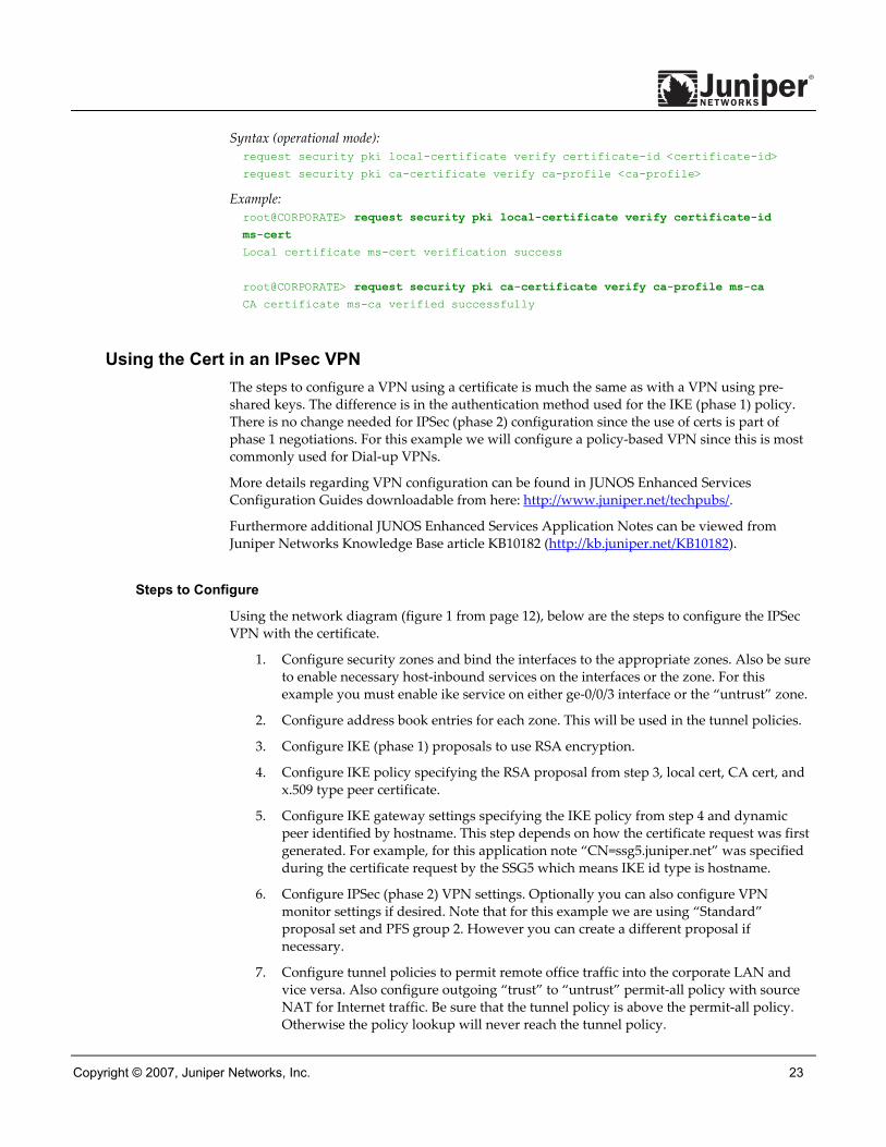
Verifying cert path
Finally, the certificate path for the local cert and any CA cert can be verified with the below command.
Copyright © 2007, Juniper Networks, Inc. 23
Syntax (operational mode): request security pki local-certificate verify certificate-id <certificate-id>
request security pki ca-certificate verify ca-profile <ca-profile>
Example: root@CORPORATE> request security pki local-certificate verify certificate-id
ms-cert
Local certificate ms-cert verification success
root@CORPORATE> request security pki ca-certificate verify ca-profile ms-ca
CA certificate ms-ca verified successfully
Using the Cert in an IPsec VPN The steps to configure a VPN using a certificate is much the same as with a VPN using pre-shared keys. The difference is in the authentication method used for the IKE (phase 1) policy. There is no change needed for IPSec (phase 2) configuration since the use of certs is part of phase 1 negotiations. For this example we will configure a policy-based VPN since this is most commonly used for Dial-up VPNs.
More details regarding VPN configuration can be found in JUNOS Enhanced Services Configuration Guides downloadable from here: http://www.juniper.net/techpubs/.
Furthermore additional JUNOS Enhanced Services Application Notes can be viewed from Juniper Networks Knowledge Base article KB10182 (http://kb.juniper.net/KB10182).
Steps to Configure
Using the network diagram (figure 1 from page 12), below are the steps to configure the IPSec VPN with the certificate.
1. Configure security zones and bind the interfaces to the appropriate zones. Also be sure to enable necessary host-inbound services on the interfaces or the zone. For this example you must enable ike service on either ge-0/0/3 interface or the “untrust” zone.
2. Configure address book entries for each zone. This will be used in the tunnel policies.
3. Configure IKE (phase 1) proposals to use RSA encryption.
4. Configure IKE policy specifying the RSA proposal from step 3, local cert, CA cert, and x.509 type peer certificate.
5. Configure IKE gateway settings specifying the IKE policy from step 4 and dynamic peer identified by hostname. This step depends on how the certificate request was first generated. For example, for this application note “CN=ssg5.juniper.net” was specified during the certificate request by the SSG5 which means IKE id type is hostname.
6. Configure IPSec (phase 2) VPN settings. Optionally you can also configure VPN monitor settings if desired. Note that for this example we are using “Standard” proposal set and PFS group 2. However you can create a different proposal if necessary.
7. Configure tunnel policies to permit remote office traffic into the corporate LAN and vice versa. Also configure outgoing “trust” to “untrust” permit-all policy with source NAT for Internet traffic. Be sure that the tunnel policy is above the permit-all policy. Otherwise the policy lookup will never reach the tunnel policy.

24 Copyright © 2007, Juniper Networks, Inc.
8. Configure tcp-mss for IPsec traffic to eliminate the possibility of fragmented TCP traffic. This will lessen the resource utilization on the device.
IPSec VPN Configuration Example for JUNOS-ES
Configuring security zones and assign interfaces to the zones
The ingress and egress zones are determined by the ingress and egress interfaces involved in the route lookup. Thus from above we can see that packets ingressing on ge-0/0/0 also means that the ingress zone is “trust” zone. Following the route lookup we can see the egress interface is ge-0/0/3 thus the egress zone is “untrust” zone. So the tunnel policy will need to be “from-zone trust to-zone untrust” and vice versa.
Syntax (configure mode): set security zones security-zone <zone-name> interfaces <interface-name>
Example: root@CORPORATE> configure
Entering configuration mode
[edit]
root@CORPORATE# set security zones security-zone trust interfaces ge-0/0/0.0
[edit]
root@CORPORATE# set security zones security-zone untrust interfaces ge-0/0/3.0
Configuring host-inbound services for each zone
Host-inbound services are for traffic destined for the JUNOS-ES device itself. This includes but is not limited to ftp, http, https, ike, ping, rlogin, rsh, snmp, ssh, telnet, tftp and traceroute. For this example we are assuming that we want to allow all such services from zone “trust”. For security reasons we are only allowing ike on the Internet facing zone “untrust” which is required for IKE negotiations to occur. However other services such as for management and/or troubleshooting can also be individually enabled if required.
Syntax (configure mode): set security zones security-zone <zone-name> host-inbound-traffic system-services
(ike | all | ping | ...)
Example: [edit]
root@CORPORATE# set security zones security-zone trust host-inbound-traffic
system-services all
[edit]
root@CORPORATE# set security zones security-zone untrust host-inbound-traffic
system-services ike
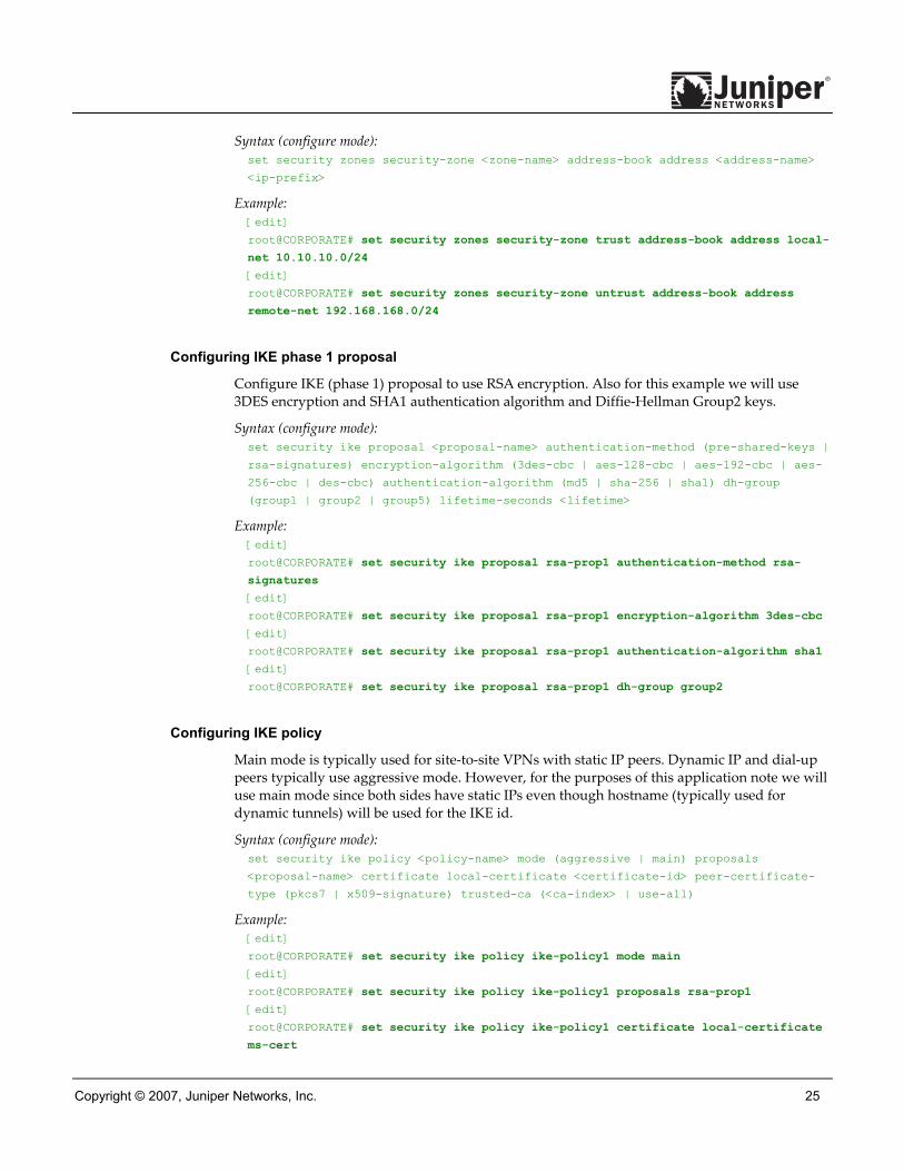
Configuring address book entries for each zone
For this example we are using address-book object names “local-net” and “remote-net”. There are some limitations with regards to which characters are supported for address-book names. Please refer to complete JUNOS-ES documentation for more details.
Copyright © 2007, Juniper Networks, Inc. 25
Syntax (configure mode): set security zones security-zone <zone-name> address-book address <address-name>
<ip-prefix>
Example: [edit]
root@CORPORATE# set security zones security-zone trust address-book address local-
net 10.10.10.0/24
[edit]
root@CORPORATE# set security zones security-zone untrust address-book address
remote-net 192.168.168.0/24
Configuring IKE phase 1 proposal
Configure IKE (phase 1) proposal to use RSA encryption. Also for this example we will use 3DES encryption and SHA1 authentication algorithm and Diffie-Hellman Group2 keys.
Syntax (configure mode): set security ike proposal <proposal-name> authentication-method (pre-shared-keys |
rsa-signatures) encryption-algorithm (3des-cbc | aes-128-cbc | aes-192-cbc | aes-
256-cbc | des-cbc) authentication-algorithm (md5 | sha-256 | sha1) dh-group
(group1 | group2 | group5) lifetime-seconds <lifetime>
Example: [edit]
root@CORPORATE# set security ike proposal rsa-prop1 authentication-method rsa-
signatures
[edit]
root@CORPORATE# set security ike proposal rsa-prop1 encryption-algorithm 3des-cbc
[edit]
root@CORPORATE# set security ike proposal rsa-prop1 authentication-algorithm sha1
[edit]
root@CORPORATE# set security ike proposal rsa-prop1 dh-group group2
Configuring IKE policy
Main mode is typically used for site-to-site VPNs with static IP peers. Dynamic IP and dial-up peers typically use aggressive mode. However, for the purposes of this application note we will use main mode since both sides have static IPs even though hostname (typically used for dynamic tunnels) will be used for the IKE id.
Syntax (configure mode): set security ike policy <policy-name> mode (aggressive | main) proposals
<proposal-name> certificate local-certificate <certificate-id> peer-certificate-
type (pkcs7 | x509-signature) trusted-ca (<ca-index> | use-all)
Example: [edit]
root@CORPORATE# set security ike policy ike-policy1 mode main
[edit]
root@CORPORATE# set security ike policy ike-policy1 proposals rsa-prop1
[edit]
root@CORPORATE# set security ike policy ike-policy1 certificate local-certificate
ms-cert

26 Copyright © 2007, Juniper Networks, Inc.
[edit]
root@CORPORATE# set security ike policy ike-policy1 certificate peer-certificate-
type x509-signature
[edit]
root@CORPORATE# set security ike policy ike-policy1 certificate trusted-ca use-all
Configuring IKE gateway
A remote IKE peer can be identified by either IP address, FQDN/u-FQDN or ASN1-DN (PKI certificates). For this example we are identifying the peer by FQDN (hostname). Therefore the gateway IKE id should be the remote peer’s domain name. It is important also to specify the correct external interface. If either the peer ID or external interface specified is incorrect then the IKE gateway will not be properly identified during phase 1 setup.
Syntax (configure mode): set security ike gateway <gateway-name> external-interface <interface-name> ike-
policy <policy-name> dynamic (hostname | inet | user-at-hostname) <ike-user-id>
Example: [edit]
root@CORPORATE# set security ike gateway ike-gate external-interface ge-0/0/3.0
[edit]
root@CORPORATE# set security ike gateway ike-gate ike-policy ike-policy1
[edit]
root@CORPORATE# set security ike gateway ike-gate dynamic hostname
ssg5.juniper.net
Configuring IPSec policy
For the purposes of this application note we are using ”Standard” proposal set which includes esp-group2-3des-sha1 and esp-group2-aes128-sha1 proposals. However a unique proposal may be created and then specified in the IPSec policy if needed.
Syntax (configure mode): set security ipsec policy <policy-name> proposal-set (basic | compatible |
standard)perfect-forward-secrecy keys (group1 | group2 | group5)
Example: [edit]
root@CORPORATE# set security ipsec policy vpn-policy1 proposal-set standard
[edit]
root@CORPORATE# set security ipsec policy vpn-policy1 perfect-forward-secrecy keys
group2
Configuring IPSec VPN with IKE gateway and IPSec policy
For this example the VPN name “ike-vpn” will need to referenced in the tunnel policy in order to be able to create a security association. Additionally if needed, idle time can be specified as well as a proxy id if different from the tunnel policy addresses.
Syntax (configure mode): set security ipsec vpn <vpn-name> ike gateway <gateway-name> ipsec-policy <policy-
name> [idle-time <value> proxy-identity local <local-prefix> remote <remote-
prefix> service <application-name>]

Copyright © 2007, Juniper Networks, Inc. 27
Example: [edit]
root@CORPORATE# set security ipsec vpn ike-vpn ike gateway ike-gate
[edit]
root@CORPORATE# set security ipsec vpn ike-vpn ike ipsec-policy vpn-policy1
Configuring bi-directional tunnel policies for VPN traffic
For this example, traffic from the corporate LAN to the remote office LAN requires a “from-zone trust to-zone untrust” tunnel policy. However if a session needs to originate from the remote LAN to the corporate LAN then a tunnel policy in the opposite direction “from-zone untrust to-zone trust” is also needed. By specifying the policy in the opposite direction as the pair-policy, the VPN becomes bi-directional. Note also that in addition to action permit we also need to specify the IPSec profile to be used. Furthermore source NAT can be enabled on the policy if desired but that is beyond the scope of this application note. Note that for tunnel policies the action is always permit. In fact if configuring a policy with action of deny, you will not see an option for specifying the tunnel.
Syntax (configure mode): edit security policies from-zone <source-zone> to-zone <dest-zone>
set policy <policy-name> match source-address <source-address> destination-address
<dest-address> application <application-name>
set policy <policy-name> then permit tunnel ipsec-vpn <vpn-name> pair-policy
<pair-policy-name>
Example: [edit]
root@CORPORATE# edit security policies from-zone trust to-zone untrust
[edit security policies from-zone trust to-zone untrust]
root@CORPORATE# set policy tunnel-policy-out match source-address local-net
[edit security policies from-zone trust to-zone untrust]
root@CORPORATE# set policy tunnel-policy-out match destination-address remote-net
[edit security policies from-zone trust to-zone untrust]
root@CORPORATE# set policy tunnel-policy-out match application any
[edit security policies from-zone trust to-zone untrust]
root@CORPORATE# set policy tunnel-policy-out then permit tunnel ipsec-vpn ike-vpn
pair-policy tunnel-policy-in
[edit security policies from-zone trust to-zone untrust]
root@CORPORATE# top edit security policies from-zone untrust to-zone trust
[edit security policies from-zone untrust to-zone trust]
root@CORPORATE# set policy tunnel-policy-in match source-address remote-net
[edit security policies from-zone untrust to-zone trust]
root@CORPORATE# set policy tunnel-policy-in match destination-address local-net
[edit security policies from-zone untrust to-zone trust]
root@CORPORATE# set policy tunnel-policy-in match application any
[edit security policies from-zone untrust to-zone trust]
root@CORPORATE# set policy tunnel-policy-in then permit tunnel ipsec-vpn ike-vpn
pair-policy tunnel-policy-out
[edit security policies from-zone untrust to-zone trust]
root@CORPORATE# exit

28 Copyright © 2007, Juniper Networks, Inc.
Configuring security policy for Internet traffic
This policy will permit all traffic from zone “trust” to zone “untrust”. By specifying “source-nat interface” the device will translate the source IP and port for outgoing traffic using the IP address of the egress interface as the source IP and random higher port for the source port. If required more granular policies can be created to permit/deny certain.
Syntax (configure mode): edit security policies from-zone <source-zone> to-zone <dest-zone>
set policy <policy-name> match source-address <source-address> destination-address
<dest-address> application <application-name>
set policy <policy-name> then permit source-nat (interface | pool <pool-name> |
pool-set <pool-set-name>)
Example: [edit]
root@CORPORATE# edit security policies from-zone trust to-zone untrust
[edit security policies from-zone trust to-zone untrust]
root@CORPORATE# set policy any-permit match source-address any
[edit security policies from-zone trust to-zone untrust]
root@CORPORATE# set policy any-permit match destination-address any
[edit security policies from-zone trust to-zone untrust]
root@CORPORATE# set policy any-permit match application any
[edit security policies from-zone trust to-zone untrust]
root@CORPORATE# set policy any-permit then permit source-nat interface
[edit security policies from-zone trust to-zone untrust]
root@CORPORATE# exit
Note that this policy MUST be below the tunnel policy since the policy list is read from top to bottom. If this policy were above the tunnel policy then the traffic would always match this policy and would not continue to the next policy. Thus no user traffic would be encrypted. To move the tunnel policy above the any-permit policy, use the insert command as below.
[edit]
root@CORPORATE# edit security policies from-zone trust to-zone untrust
[edit security policies from-zone trust to-zone untrust]
root@CORPORATE# insert policy tunnel-policy-out before policy any-permit
[edit security policies from-zone trust to-zone untrust]
root@CORPORATE# exit
Configuring tcp-mss for TCP traffic across the tunnel
Tcp-mss is negotiated as part of the TCP 3-way handshake. It limits the maximum size of a TCP segment to better fit the MTU limits on a network. This is especially important for VPN traffic as the IPSec encapsulation overhead along with the IP and frame overhead can cause the resulting ESP packet to exceed the MTU of the physical interface causing fragmentation. Fragmentation increases bandwidth and device resources and is always best avoided. Note the value of 1350 is a recommended starting point for most ethernet-based networks with MTU of 1500 or greater. This value may need to be altered if any device in the path has lower MTU and/or if there is any added overhead such as PPP, frame relay, etc. As a general rule you may need to experiment with different tcp-mss values to obtain optimal performance.
Syntax (configure mode): set security flow tcp-mss ipsec-vpn mss <mss-value>

Copyright © 2007, Juniper Networks, Inc. 29
Example: [edit]
root@CORPORATE# set security flow tcp-mss ipsec-vpn mss 1350
[edit]
root@CORPORATE# commit and-quit
commit complete
Exiting configuration mode
SSG Configuration Example The focus of this application note is on JUNOS-ES configuration and troubleshooting. For the purpose of completing the diagram above, a sample of relevant configurations is provided from an SSG5 device strictly for reference. However the concepts with regard to configuration of policy-based VPNs for Juniper Networks Firewall/VPN products are well documented in the Concepts and Examples (C&E) guides. Thus we will not focus on the SSG configuration in this application note. For reference the SSG C&E guides can be found here: http://www.juniper.net/techpubs/software/screenos/.
Configuration example for SSG5
set interface ethernet0/6 ip 192.168.168.1/24
set interface ethernet0/6 route
set interface ethernet0/0 ip 2.2.2.2/30
set interface ethernet0/0 route
set flow tcp-mss 1350
set domain juniper.net
set hostname ssg5
set pki x509 default cert-path partial
set pki x509 dn country-name "US"
set pki x509 dn state-name "CA"
set pki x509 dn local-name "Sunnyvale"
set pki x509 dn org-name "Juniper Networks"
set pki x509 dn org-unit-name "Sales"
set pki x509 dn ip 2.2.2.2
set dns host dns1 4.2.2.1
set dns host dns2 4.2.2.2
set address "Trust" "local-net" 192.168.168.0 255.255.255.0
set address "Untrust" "corp-net" 10.10.10.0 255.255.255.0
set ike gateway "corp-ike" address 1.1.1.2 Main outgoing-interface ethernet0/0
proposal "rsa-g2-3des-sha"
set vpn "corp-vpn" gateway "corp-ike" replay tunnel idletime 0 sec-level standard
set policy id 11 from "Trust" to "Untrust" "local-net" "corp-net" "ANY" tunnel vpn
"corp-vpn" pair-policy 10
set policy id 10 from "Untrust" to "Trust" "corp-net" "local-net" "ANY" tunnel vpn
"corp-vpn" pair-policy 11
set policy id 1 from "Trust" to "Untrust" "ANY" "ANY" "ANY" nat src permit
set ntp server "130.126.24.24"
set route 0.0.0.0/0 interface ethernet0/0 gateway 2.2.2.1
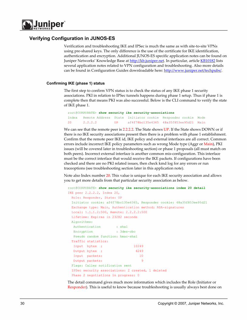
30 Copyright © 2007, Juniper Networks, Inc.
Verifying Configuration in JUNOS-ES Verification and troubleshooting IKE and IPSec is much the same as with site-to-site VPNs using pre-shared keys. The only difference is the use of the certificate for IKE identification, authentication and encryption. Additional JUNOS-ES specific application notes can be found on Juniper Networks’ Knowledge Base at http://kb.juniper.net. In particular, article KB10182 lists several application notes related to VPN configuration and troubleshooting. Also more details can be found in Configuration Guides downloadable here: http://www.juniper.net/techpubs/.
Confirming IKE (phase 1) status
The first step to confirm VPN status is to check the status of any IKE phase 1 security associations. PKI in relation to IPSec tunnels happens during phase 1 setup. Thus if phase 1 is complete then that means PKI was also successful. Below is the CLI command to verify the state of IKE phase 1.
root@CORPORATE> show security ike security-associations
Index Remote Address State Initiator cookie Responder cookie Mode
20 2.2.2.2 UP af4f78bc135e4365 48a35f853ee95d21 Main
We can see that the remote peer is 2.2.2.2. The State shows UP. If the State shows DOWN or if there is no IKE security associations present then there is a problem with phase 1 establishment. Confirm that the remote peer IKE id, IKE policy and external interfaces are all correct. Common errors include incorrect IKE policy parameters such as wrong Mode type (Aggr or Main), PKI issues (will be covered later in troubleshooting section) or phase 1 proposals (all must match on both peers). Incorrect external interface is another common mis-configuration. This interface must be the correct interface that would receive the IKE packets. If configurations have been checked and there are no PKI related issues, then check kmd log for any errors or run traceoptions (see troubleshooting section later in this application note).
Note also Index number 20. This value is unique for each IKE security association and allows you to get more details from that particular security association as below.
root@CORPORATE> show security ike security-associations index 20 detail
IKE peer 2.2.2.2, Index 20,
Role: Responder, State: UP
Initiator cookie: af4f78bc135e4365, Responder cookie: 48a35f853ee95d21
Exchange type: Main, Authentication method: RSA-signatures
Local: 1.1.1.2:500, Remote: 2.2.2.2:500
Lifetime: Expires in 23282 seconds
Algorithms:
Authentication : sha1
Encryption : 3des-cbc
Pseudo random function: hmac-sha1
Traffic statistics:
Input bytes : 10249
Output bytes : 4249
Input packets: 10
Output packets: 9
Flags: Caller notification sent
IPSec security associations: 2 created, 1 deleted
Phase 2 negotiations in progress: 0
The detail command gives much more information which includes the Role (Initiator or Responder). This is useful to know because troubleshooting is usually always best done on
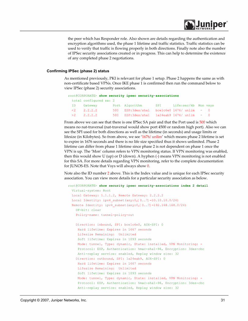
Copyright © 2007, Juniper Networks, Inc. 31
the peer which has Responder role. Also shown are details regarding the authentication and encryption algorithms used, the phase 1 lifetime and traffic statistics. Traffic statistics can be used to verify that traffic is flowing properly in both directions. Finally note also the number of IPSec security associations created or in progress. This can help to determine the existence of any completed phase 2 negotiations.
Confirming IPSec (phase 2) status
As mentioned previously, PKI is relevant for phase 1 setup. Phase 2 happens the same as with non-certificate based VPNs. Once IKE phase 1 is confirmed then run the command below to view IPSec (phase 2) security associations.
root@CORPORATE> show security ipsec security-associations
total configured sa: 2
ID Gateway Port Algorithm SPI Life:sec/kb Mon vsys
<2 2.2.2.2 500 ESP:3des/sha1 bce1c6e0 1676/ unlim - 0
>2 2.2.2.2 500 ESP:3des/sha1 1a24eab9 1676/ unlim - 0
From above we can see that there is one IPSec SA pair and that the Port used is 500 which means no nat-traversal (nat-traversal would show port 4500 or random high port). Also we can see the SPI used for both directions as well as the lifetime (in seconds) and usage limits or lifesize (in Kilobytes). So from above, we see ‘1676/ unlim’ which means phase 2 lifetime is set to expire in 1676 seconds and there is no life size specified thus it shows unlimited. Phase 2 lifetime can differ from phase 1 lifetime since phase 2 is not dependent on phase 1 once the VPN is up. The ‘Mon’ column refers to VPN monitoring status. If VPN monitoring was enabled, then this would show U (up) or D (down). A hyphen (-) means VPN monitoring is not enabled for this SA. For more details regarding VPN monitoring, refer to the complete documentation for JUNOS-ES. Note that Vsys will always show 0.
Note also the ID number 2 above. This is the Index value and is unique for each IPSec security association. You can view more details for a particular security association as below.
root@CORPORATE> show security ipsec security-associations index 2 detail
Virtual-system: Root
Local Gateway: 1.1.1.2, Remote Gateway: 2.2.2.2
Local Identity: ipv4_subnet(any:0,[0..7]=10.10.10.0/24)
Remote Identity: ipv4_subnet(any:0,[0..7]=192.168.168.0/24)
DF-bit: clear
Policy-name: tunnel-policy-out
Direction: inbound, SPI: bce1c6e0, AUX-SPI: 0
Hard lifetime: Expires in 1667 seconds
Lifesize Remaining: Unlimited
Soft lifetime: Expires in 1093 seconds
Mode: tunnel, Type: dynamic, State: installed, VPN Monitoring: -
Protocol: ESP, Authentication: hmac-sha1-96, Encryption: 3des-cbc
Anti-replay service: enabled, Replay window size: 32
Direction: outbound, SPI: 1a24eab9, AUX-SPI: 0
Hard lifetime: Expires in 1667 seconds
Lifesize Remaining: Unlimited
Soft lifetime: Expires in 1093 seconds
Mode: tunnel, Type: dynamic, State: installed, VPN Monitoring: -
Protocol: ESP, Authentication: hmac-sha1-96, Encryption: 3des-cbc
Anti-replay service: enabled, Replay window size: 32

32 Copyright © 2007, Juniper Networks, Inc.
From above we can see Local Identity and Remote Identity. These elements comprise the proxy ID for this SA. Proxy ID mismatch is a very common reason for phase 2 failing to complete. For policy-based VPNs the proxy ID is derived from the tunnel policy. From the tunnel policy the local address and remote address are derived from the address book entries, and the service is derived from the application configured for the policy. If phase 2 fails due to a proxy ID mismatch then confirm from the policy which address book entries are configured and double-check the addresses to confirm they match what is being sent. Also double-check the service to ensure that the ports match what is being sent.
Note that if multiple objects are configured in a tunnel policy for either source address, destination address or application then the resulting proxy ID for that parameter would be changed to zeroes. For example assume the tunnel policy has multiple local addresses of 10.10.10.0/24 and 10.10.20.0/24, remote address 192.168.168.0/24, and application junos-http. The resulting proxy-ID would be local 0.0.0.0/0, remote 192.168.168.0/24, service 80.
This can affect interoperability if the remote peer is not also configured for the second subnet. Also for some third-party vendors you may need to manually enter the proxy ID to match. If IPSec cannot complete, then check the kmd log or set traceoptions as detailed in the troubleshooting section of this application note.
Checking statistics and errors for an IPSec SA
The command below is used to check ESP and AH counters and for any errors with a particular IPSec security associations.
root@CORPORATE> show security ipsec statistics index 2
ESP Statistics:
Encrypted bytes: 674784
Decrypted bytes: 309276
Encrypted packets: 7029
Decrypted packets: 7029
AH Statistics:
Input bytes: 0
Output bytes: 0
Input packets: 0
Output packets: 0
Errors:
AH authentication failures: 0, Replay errors: 0
ESP authentication failures: 0, ESP decryption failures: 0
Bad headers: 0, Bad trailers: 0
You normally do not want to see error values other than zero. However if you are experiencing packet loss issues across a VPN, then one approach is to run the above command multiple times and confirm that the Encrypted and Decrypted packet counters are incrementing. Also see if any of the error counters increment while you are experiencing the issue. It may also be necessary to enable security flow traceoptions (see troubleshooting section) to see which ESP packets are experiencing errors and why.
Testing traffic flow across the VPN
Once you have confirmed status of phase 1 and phase 2, then the next step is to test traffic flow across the VPN. One way to test traffic flow is through pings. We can ping from local host PC to remote host PC. We can also initiate pings from the JUNOS-ES device itself. Below is an example of ping testing from the JUNOS-ES device to the remote PC host.

Copyright © 2007, Juniper Networks, Inc. 33
root@CORPORATE> ping 192.168.168.10 interface ge-0/0/0 count 5
PING 192.168.168.10 (192.168.168.10): 56 data bytes
64 bytes from 192.168.168.10: icmp_seq=0 ttl=127 time=8.287 ms
64 bytes from 192.168.168.10: icmp_seq=1 ttl=127 time=4.119 ms
64 bytes from 192.168.168.10: icmp_seq=2 ttl=127 time=5.399 ms
64 bytes from 192.168.168.10: icmp_seq=3 ttl=127 time=4.361 ms
64 bytes from 192.168.168.10: icmp_seq=4 ttl=127 time=5.137 ms
--- 192.168.168.10 ping statistics ---
5 packets transmitted, 5 packets received, 0% packet loss
round-trip min/avg/max/stddev = 4.119/5.461/8.287/1.490 ms
Note that when initiating pings from the JUNOS-ES device the source interface needs to be specified in order to be sure that route lookup will be correct and the appropriate zones can be referenced in policy lookup. In this case since ge-0/0/0.0 resides in the same security zone as the local host PC then ge-0/0/0 will need to be specified in pings so that the policy lookup can be from zone “trust” to zone “untrust”. Likewise we can initiate a ping from the remote host to the local host. Also we can initiate a ping from the SSG5 itself as below.
ssg5-> ping 10.10.10.10 from ethernet0/6
Type escape sequence to abort
Sending 5, 100-byte ICMP Echos to 10.10.10.10, timeout is 1 seconds from
ethernet0/6
!!!!!
Success Rate is 100 percent (5/5), round-trip time min/avg/max=4/4/5 ms
If pings fail from either direction then this could indicate an issue with routing, policy, end host or perhaps an issue with the encryption/decryption of the ESP packets. One way to check is to view IPSec statistics as mentioned above to see if any errors are reported. Also you can confirm end host connectivity by pinging from a host on the same subnet as the end host. Assuming that the end host is reachable by other hosts then likely the issue is not with the end host. For routing and policy issues, enable security flow traceoptions which is beyond the scope of this application note but is documented in other VPN related application notes for JUNOS-ES.
Troubleshooting Basics Basic troubleshooting begins by first isolating the issue and then focusing the debugging efforts on the area where the problem is occurring. One common approach is to start with the lowest layer of the OSI model and work your way up the OSI stack to confirm at which layer the failure occurs.
Following this methodology the first step to troubleshooting is to confirm the physical connectivity of the Internet link at the physical and data link levels. Next, using ping, confirm that the JUNOS-ES device has connectivity to the Internet next-hop followed by confirming connectivity to the remote IKE peer. Assuming that has all been confirmed then confirm that IKE phase 1 can complete by running the verification commands as shown above. Once phase 1 is confirmed then confirm phase 2. Finally confirm traffic is flowing across the VPN. If the VPN is not in UP state then there is very little reason to test any transit traffic across the VPN. Likewise if phase 1 was not successful, then checking for phase 2 issues is pointless.
To troubleshoot issues further at the different levels, configure traceoptions. Traceoptions are enabled in configuration mode and are a part of a JUNOS-ES operating configuration. This

34 Copyright © 2007, Juniper Networks, Inc.
means that a configuration commit is necessary before a traceoption will take affect. Likewise, removing traceoptions require deleting or deactivating the configuration followed by a commit. By enabling a traceoption flag, the data from the traceoption will be written to a log file which may be predetermined or manually configured and stored in flash memory. This means that any trace logs will be retained even after a system reboot. Keep in mind the available storage on flash before implementing traceoptions. You can check your available storage as below.
root@CORPORATE> show system storage
Filesystem Size Used Avail Capacity Mounted on
/dev/ad0s1a 213M 74M 137M 35% /
devfs 1.0K 1.0K 0B 100% /dev
devfs 1.0K 1.0K 0B 100% /dev/
/dev/md0 180M 180M 0B 100% /junos
/cf 213M 74M 137M 35% /junos/cf
devfs 1.0K 1.0K 0B 100% /junos/dev/
procfs 4.0K 4.0K 0B 100% /proc
/dev/bo0s1e 24M 13K 24M 0% /config
/dev/md1 168M 7.6M 147M 5% /mfs
/cf/var/jail 213M 74M 137M 35% /jail/var
As shown above, /dev/ad0s1a represents the onboard flash memory and is currently at 35% capacity. You can also view available storage on the J-Web homepage under System Storage. The output of all traceoptions write to logs stored in directory /var/log. To view a list of all logs in /var/log directory, run operational mode command: “show log”.
Checking traceoption logs
As noted earlier, enabling traceoptions begins the logging of the output to the filenames specified or to the default log file for the traceoption. View the appropriate log to view the trace output. Below are the commands to view the appropriate logs.
root@CORPORATE> show log kmd
root@CORPORATE> show log pkid
root@CORPORATE> show log security-trace
root@CORPORATE> show log messages
Logs can also be uploaded to an FTP server with the “file copy” command.
Syntax (operational mode): file copy <path/filename> <dest-path/filename>
Example: root@CORPORATE> file copy /var/log/kmd ftp://10.10.10.10/kmd.log
ftp://10.10.10.10/kmd.log 100% of 35 kB 12 MBps
Troubleshooting IKE, PKI and IPSec Issues To view success or failure messages in IKE or IPSec, view the kmd log with command: “show log kmd”. Although the kmd log can show some general messages, it may be necessary to obtain additional details. For details, enable IKE and PKI traceoptions. Note as a general rule, it is always best to troubleshoot on the peer which is the Responder. Obtaining trace output from the Initiator may also be useful in conjunction. However, obtaining trace output from only the Initiator alone may not reveal the cause of a failure.

Copyright © 2007, Juniper Networks, Inc. 35
Enabling IKE traceoptions for phase 1 and phase 2 negotiation issues
Below is an example of all IKE traceoptions.
root@CORPORATE> configure
Entering configuration mode
[edit]
root@CORPORATE# edit security ike traceoptions
[edit security ike traceoptions]
root@CORPORATE# set file ?
Possible completions:
<filename> Name of file in which to write trace information
files Maximum number of trace files (2..1000)
match Regular expression for lines to be logged
no-world-readable Don't allow any user to read the log file
size Maximum trace file size (10240..1073741824)
world-readable Allow any user to read the log file
[edit security ike traceoptions]
root@CORPORATE# set flag ?
Possible completions:
all Trace everything
certificates Trace certificate events
database Trace security associations database events
general Trace general events
ike Trace IKE module processing
parse Trace configuration processing
policy-manager Trace policy manager processing
routing-socket Trace routing socket messages
timer Trace internal timer events
By default if no file name is specified then all IKE traceoptions write to the kmd log. However you can specify a different filename if desired. To write trace data to the log you must specify at least one flag option. Option `file size’ determines the maximum size of a log file in bytes. For example 1m or 1000000 will generate a maximum file size of 1 MB. Option `file files’ determines the maximum number of log files that will be generated and stored in flash. Remember to commit the changes to start the trace.
In addition to IKE traceoptions, enabling PKI traceoptions is also a good idea to isolate whether an IKE failure is related to the certificate or due to a non-PKI issue. Below is an example of all PKI traceoptions.
root@CORPORATE> configure
Entering configuration mode
[edit]
root@CORPORATE# edit security pki traceoptions
[edit security pki traceoptions]
root@CORPORATE# set file ?
Possible completions:
<filename> Name of file in which to write trace information
files Maximum number of trace files (2..1000)
match Regular expression for lines to be logged
no-world-readable Don't allow any user to read the log file
size Maximum trace file size (10240..1073741824)
world-readable Allow any user to read the log file
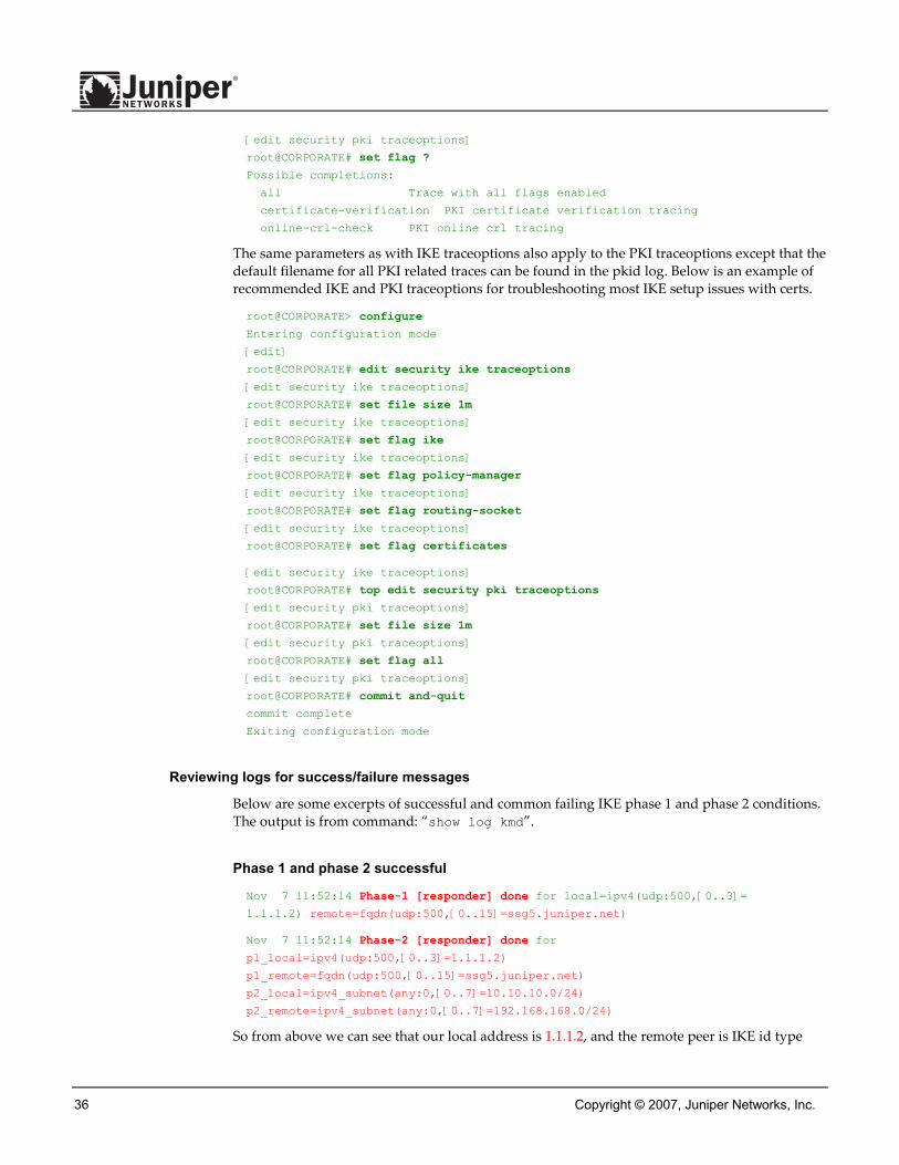
36 Copyright © 2007, Juniper Networks, Inc.
[edit security pki traceoptions]
root@CORPORATE# set flag ?
Possible completions:
all Trace with all flags enabled
certificate-verification PKI certificate verification tracing
online-crl-check PKI online crl tracing
The same parameters as with IKE traceoptions also apply to the PKI traceoptions except that the default filename for all PKI related traces can be found in the pkid log. Below is an example of recommended IKE and PKI traceoptions for troubleshooting most IKE setup issues with certs.
root@CORPORATE> configure
Entering configuration mode
[edit]
root@CORPORATE# edit security ike traceoptions
[edit security ike traceoptions]
root@CORPORATE# set file size 1m
[edit security ike traceoptions]
root@CORPORATE# set flag ike
[edit security ike traceoptions]
root@CORPORATE# set flag policy-manager
[edit security ike traceoptions]
root@CORPORATE# set flag routing-socket
[edit security ike traceoptions]
root@CORPORATE# set flag certificates
[edit security ike traceoptions]
root@CORPORATE# top edit security pki traceoptions
[edit security pki traceoptions]
root@CORPORATE# set file size 1m
[edit security pki traceoptions]
root@CORPORATE# set flag all
[edit security pki traceoptions]
root@CORPORATE# commit and-quit
commit complete
Exiting configuration mode
Reviewing logs for success/failure messages
Below are some excerpts of successful and common failing IKE phase 1 and phase 2 conditions. The output is from command: “show log kmd”.
Phase 1 and phase 2 successful
Nov 7 11:52:14 Phase-1 [responder] done for local=ipv4(udp:500,[0..3]=
1.1.1.2) remote=fqdn(udp:500,[0..15]=ssg5.juniper.net)
Nov 7 11:52:14 Phase-2 [responder] done for
p1_local=ipv4(udp:500,[0..3]=1.1.1.2)
p1_remote=fqdn(udp:500,[0..15]=ssg5.juniper.net)
p2_local=ipv4_subnet(any:0,[0..7]=10.10.10.0/24)
p2_remote=ipv4_subnet(any:0,[0..7]=192.168.168.0/24)
So from above we can see that our local address is 1.1.1.2, and the remote peer is IKE id type

Copyright © 2007, Juniper Networks, Inc. 37
hostname with FQDN of ssg5.juniper.net. Also udp: 500 indicates that no nat-traversal was negotiated. You should see a phase 1 done message along with the role (initiator or responder). Next you should also see a phase 2 done message with proxy ID information. At this point you can confirm that the IPSec SA is up using the verification commands mentioned in previous section.
Phase 1 failing to complete, example 1
Nov 7 11:52:14 Phase-1 [responder] failed with error(No proposal chosen) for
local=unknown(any:0,[0..0]=) remote=fqdn(udp:500,[0..15]=ssg5.juniper.net)
Nov 7 11:52:14 1.1.1.2:500 (Responder) <-> 2.2.2.2:500 { 011359c9 ddef501d -
2216ed2a bfc50f5f [-1] / 0x00000000 } IP; Error = No proposal chosen (14)
So from above we can see that our local address is 1.1.1.2, and the remote peer is IKE id type hostname with FQDN of ssg5.juniper.net. The role is responder. The reason for failing is due to No proposal chosen. This is likely mismatched phase 1 proposals. To resolve this issue, confirm that phase 1 proposals match on both peers. Also confirm that a tunnel policy exists for the VPN.
Phase 1 failing to complete, example 2
Nov 7 12:06:36 Unable to find phase-1 policy as remote peer:2.2.2.2 is not
recognized.
Nov 7 12:06:36 Phase-1 [responder] failed with error(Authentication failed) for
local=ipv4(udp:500,[0..3]=1.1.1.2) remote=ipv4(any:0,[0..3]=2.2.2.2)
Nov 7 12:06:36 1.1.1.2:500 (Responder) <-> 2.2.2.2:500 { f725ca38 dad47583 -
dab1ba4c ae26674b [-1] / 0x00000000 } IP; Error = Authentication failed (24)
So from above again we can see that our local address is 1.1.1.2, and the remote peer is 2.2.2.2. The role is responder. The reason for failing indicates that the peer is not recognized, thus Authentication failed. In the case of IKE with PKI certs, peer not recognized typically indicates incorrect IKE id type was specified or IKE id itself was not entered correctly. This needs to be checked first before the phase 1 proposal is checked. To resolve this issue, confirm that the local peer has the correct peer IKE id type specified based on how the remote peer cert was generated. Also confirm that the local peer is configured with the correct id information based on the SubjectAlternativeName or DN information in the received remote peer certificate.
Phase 1 failing to complete, example 3
Nov 7 13:52:39 Phase-1 [responder] failed with error(Timeout) for
local=unknown(any:0,[0..0]=) remote=ipv4(any:0,[0..3]=2.2.2.2)
So from above again we can see that the remote peer is 2.2.2.2. The role is responder. This error means that IKE phase 1 was waiting for a response, but did not receive one in time. This could indicate that either the IKE packet may have been lost enroute to the remote peer or perhaps the remote peer response was not received. This message may also indicate an issue with PKI failing. The timeout could be a result of waiting on a response from the PKI daemon. If that is the case then review PKI traceoption output to see if there is a problem with PKI.
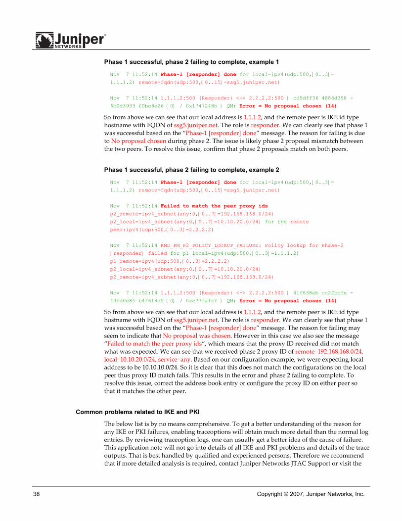
38 Copyright © 2007, Juniper Networks, Inc.
Phase 1 successful, phase 2 failing to complete, example 1
Nov 7 11:52:14 Phase-1 [responder] done for local=ipv4(udp:500,[0..3]=
1.1.1.2) remote=fqdn(udp:500,[0..15]=ssg5.juniper.net)
Nov 7 11:52:14 1.1.1.2:500 (Responder) <-> 2.2.2.2:500 { cd9dff36 4888d398 -
6b0d3933 f0bc8e26 [0] / 0x1747248b } QM; Error = No proposal chosen (14)
So from above we can see that our local address is 1.1.1.2, and the remote peer is IKE id type hostname with FQDN of ssg5.juniper.net. The role is responder. We can clearly see that phase 1 was successful based on the “Phase-1 [responder] done” message. The reason for failing is due to No proposal chosen during phase 2. The issue is likely phase 2 proposal mismatch between the two peers. To resolve this issue, confirm that phase 2 proposals match on both peers.
Phase 1 successful, phase 2 failing to complete, example 2
Nov 7 11:52:14 Phase-1 [responder] done for local=ipv4(udp:500,[0..3]=
1.1.1.2) remote=fqdn(udp:500,[0..15]=ssg5.juniper.net)
Nov 7 11:52:14 Failed to match the peer proxy ids
p2_remote=ipv4_subnet(any:0,[0..7]=192.168.168.0/24)
p2_local=ipv4_subnet(any:0,[0..7]=10.10.20.0/24) for the remote
peer:ipv4(udp:500,[0..3]=2.2.2.2)
Nov 7 11:52:14 KMD_PM_P2_POLICY_LOOKUP_FAILURE: Policy lookup for Phase-2
[responder] failed for p1_local=ipv4(udp:500,[0..3]=1.1.1.2)
p1_remote=ipv4(udp:500,[0..3]=2.2.2.2)
p2_local=ipv4_subnet(any:0,[0..7]=10.10.20.0/24)
p2_remote=ipv4_subnet(any:0,[0..7]=192.168.168.0/24)
Nov 7 11:52:14 1.1.1.2:500 (Responder) <-> 2.2.2.2:500 { 41f638eb cc22bbfe -
43fd0e85 b4f619d5 [0] / 0xc77fafcf } QM; Error = No proposal chosen (14)
So from above we can see that our local address is 1.1.1.2, and the remote peer is IKE id type hostname with FQDN of ssg5.juniper.net. The role is responder. We can clearly see that phase 1 was successful based on the “Phase-1 [responder] done” message. The reason for failing may seem to indicate that No proposal was chosen. However in this case we also see the message “Failed to match the peer proxy ids“, which means that the proxy ID received did not match what was expected. We can see that we received phase 2 proxy ID of remote=192.168.168.0/24, local=10.10.20.0/24, service=any. Based on our configuration example, we were expecting local address to be 10.10.10.0/24. So it is clear that this does not match the configurations on the local peer thus proxy ID match fails. This results in the error and phase 2 failing to complete. To resolve this issue, correct the address book entry or configure the proxy ID on either peer so that it matches the other peer.
Common problems related to IKE and PKI
The below list is by no means comprehensive. To get a better understanding of the reason for any IKE or PKI failures, enabling traceoptions will obtain much more detail than the normal log entries. By reviewing traceoption logs, one can usually get a better idea of the cause of failure. This application note will not go into details of all IKE and PKI problems and details of the trace outputs. That is best handled by qualified and experienced persons. Therefore we recommend that if more detailed analysis is required, contact Juniper Networks JTAC Support or visit the

Copyright © 2007, Juniper Networks, Inc. 39
Juniper Networks Support Website at http://www.juniper.net/support for further assistance. Below are some of the common problems related to IKE and PKI.
• Clock, date, time zone, or daylight savings settings are incorrect. It’s best to use NTP to keep the clock accurate.
• Make sure to use a two-letter country code in the ʺC=ʺ (country) field of the DN. For example, use “US” and not “USA” nor “United States”. Some CA’s require that the Country field of the DN be populated and only with a two-letter code.
• If the peer cert uses multiple ʺOU=ʺ or ʺCN=ʺ fields, use distinguished name with container method (the sequence must be maintained and is case sensitive).
• If certificate is not valid yet, check the system clock otherwise adjust the system time zone or just add a day in clock for quick tests.
• Make sure the configured IKE id type and value match.
• PKI may fail due to Revocation Check failure. One way to see if that is the case would be to temporarily disable revocation check and see if IKE phase 1 is then able to complete. To disable revocation checking, use the following command in configure mode: ʺset security pki ca-profile <ca-profile> revocation-check disableʺ followed by ʺcommitʺ.
PKI FAQ (Frequently Asked Questions) Q. Does Juniper provide a CA with its products?
A. No, a customer wishing to use a PKI needs to obtain 3rd party CA software to implement the PKI or use a service like Verisign.
Q. What version of X.509 certs are supported (V1 or V3)?
A. Juniper will support either. However, you need to use V3 if you want to use the SubjectAlternativeName extension field for a non-DN IKE id type (e.g., IP address, email address, or FQDN).
Q. Does the JUNOS-ES device support multiple certificates?
A. Yes, the JUNOS-ES device can generate multiple key pairs, multiple cert requests, and have multiple local certificates loaded. The specific quantity depends on upon the particular platform.
Q. Can the JUNOS-ES device use the same DN for different local certs?
A. In a particular Juniper device, we do not support multiple certs with the same Subject (or DN) name. Therefore, it is recommended to use a separate subject name for every key pair to avoid confusion. Some CA’s also have limitations on supporting multiple key pairs for the same subject name.
Q. Can the JUNOS-ES device auto-generate CN values such as FQDN and serial number in the DN?
A. JUNOS-ES does not auto-generate these CN values. The FQDN or any other CN values would need to be specified during the certificate request procedure.
Q. Does the JUNOS-ES device support a hierarchical CA chain?
A. Yes, the JUNOS-ES device can validate certs up through a chain of CA certs.

40 Copyright © 2007, Juniper Networks, Inc.
Q. How many levels of a CA chain can the JUNOS-ES device validate?
A. Seven.
Q. I’ve got many levels in my chain and my CDP servers are slow; how do I keep IKE from timing out?
A. Try adjusting the refresh interval for the CRL such that the CRL will not be checked as frequently. This is at the expense of potentially allowing a cert which may have been revoked by the CA.
Q. Does Juniper support PKCS10 for certificate requests?
A. Yes, P10 cert requests can be generated by the JUNOS-ES device and then copied from the CLI, sent via email, or uploaded onto an FTP server.
Q. Does Juniper support PKCS12 cert packages?
A. No, a JUNOS-ES device will not accept a PKCS12 file; The JUNOS-ES device must generate its own private key. Also, a Juniper device will not generate a PKCS12 file for exporting its private/public keys and certificate. This philosophy helps minimize the possibility to steal a device’s keys and thereby impersonate that device.
Q. Does the private key ever leave the JUNOS-ES device?
A. No, but in future JUNOS-ES releases, the private key may be copied from the active to the backup unit of a HA (high availability) or JSRP pair as an RTO (run-time object).
Q. What special characters should I be leery of?
A. We support printable Strings, minus reserved characters we use as deliminators like the comma. Names with ʹ_ʹ or underscore can also potentially cause problems.
Q. What RFC does Juniper support for PKI?
A. We follow RFC3280. We also have all the needed security features of RFC2459 (predecessor of RFC3280).
Q. What are the possible PKI objects stored in flash and run-time memory?
A. CA cert, CA CRL, CA-profile config, local key-pair, and local cert or pending-cert.
Q. How do these relate?
A. Each CA cert will typically use 3 objects (CA cert, CRL, & CA-profile config). Each local cert will use 2 objects (cert & key-pair). A pending cert is just a PKCS10 file that has been generated and sent to a CA. Once the signed cert from the CA is installed the “pending cert” object is replaced with the “local cert”.
Q. So what are average sizes for these various items?
A. Average size of items: - CRL, varies depending on how many certs a particular CA has revoked: min 300 bytes to max 5MB, - Cert, average 2K bytes each, - Key pair, average 1K bytes each, - CA-profile configuration, average 500 bytes each.
Q. What is the maximum size of a CRL?
A. The maximum size supported in JUNOS-ES version 8.5 is 5MB.
Copyright © 2007, Juniper Networks, Inc. 41
Q. How do you disable CRL checking?
A. CRL checking is configurable per CA-profile.The command syntax to disable CRL checking is: ʺset security pki ca-profile <ca-profile> revocation-check disable" followed by "commitʺ.
Q. Why doesn’t the JUNOS-ES device use or support two sets of keys for VPN?
A. Most people set up a PKI for email and file encryption and signing. When doing so you learn that you should use two sets of keys. While you certainly want two sets of keys when encrypting emails and files (one set for signing and one set for encryption) you donʹt need that for VPN. RSA keys are only used for authentication in IPSec and so you donʹt need the second set of keys for things like long-term storage of encrypted material.
Q. Does Juniper support CA Cross-certification? In other words, if one Juniper device uses a cert from one root CA and another Juniper device uses a cert from a different root CA and the two root CAʹs are cross-certified will the two Juniperʹs properly validate each otherʹs certs and form the VPN tunnel?
A. Yes, it can be done by using PKCS7 cert type as well. Via the cross-certificate, we can form a full certificate path to the root certificate stored locally.
Q. Which certificate formats are supported by JUNOS-ES?
A. Juniper follows the PKI profile described in RFC 3280. We support installation of end-entity (EE) or certificate authority (CA) certificate. We support encodings include X509 or PKCS7, DER or PEM. We are compatible with X509 v3 and can handle extensions defined in RFC3280.
Q. Does JUNOS-ES support high availability (HA) for PKI certificates?
A. JUNOS-ES 8.5 does not currently support HA or JSRP with PKI. Future releases may support the transferring of a device key-pair and local certs between two HA peers. Check release notes for upcoming releases to see if this is supported in releases later than 8.5.
Q. How does the public key of a key pair get bound to a cert request?
A. When generating a new key pair, a certificate-id must be specified. This certificate-id is also used for the cert request and again when the local cert is loaded. To completely delete a certificate request and key pair, use the ʺclear security pkiʺ operational mode command. Two clear operations are needed. One to clear the cert request and then another to clear the key pair.
Q. Why not delete both the cert and the key pair at the same time?
A. Some administrators prefer the ability to keep the same key pair but use a new certificate with them. This allows for the deletion of the old certificate without destroying the old key pair.
Q. Does JUNOS-ES support DSA keys?
A. No, currently only RSA keys are supported. DSA keys may be supported in future releases.
Q. Is JUNOS-ES ICSA certified?
A. Not yet, although many of the security features in JUNOS-ES was sourced from Juniper Networks ScreenOS products which are certified for version 1.2. For more information regarding ICSA certification refer to ICSA Labs website: http://www.icsalabs.com/
Q. Is OCSP supported for revocation checking?
A. Not currently, but may be supported in a future release.
42 Copyright © 2007, Juniper Networks, Inc.
Q. Are there special characters to consider when doing PKI?
A. Yes, the comma “,” is a special character in ASN.1 DN and requires an escape character to use which is the backslash “\”. The UTF-8 encoded string should not have any of the following characters: - a space or ʺ#ʺ character occurring at the beginning of the string; - a space character occurring at the end of the string; - one of the characters ʺ,ʺ comma, ʺ+ʺ plus, ʺʺʺ double quote, ʺ\ʺ backslash, ʺ<ʺ less than or left triangle bracket, ʺ>ʺ greater than or right triangle bracket, or ʺ;ʺ semi-colon. If the comma “,” character needs to be escaped then it should be prefixed by a backslash (ʹ\ʹ ASCII 92).
Q. I want my CDP function to communicate through a VPN tunnel. How do I set that up so the JUNOS-ES device will source the IP from an internal interface that matches a tunnel definition and not source the packet from the egress interface which doesn’t match a tunnel policy (even though that interface is the tunnel endpoint/gateway IP itself)?
A. This is currently not supported in JUNOS-ES.

Copyright © 2007, Juniper Networks, Inc. 43
Appendix A: Show Configuration Below is the output of show configuration. For reference, highlighted are traceoption configurations for troubleshooting purposes. Always remember to delete or deactivate the traceoptions once troubleshooting is complete.
root@CORPORATE> show configuration | no-more
system {
host-name CORPORATE;
time-zone PST8PDT;
root-authentication {
encrypted-password "$1$wUchK29B$IACQWVtsyF2PBlKtl1Air."; ## SECRET-DATA
}
name-server {
4.2.2.1;
4.2.2.2;
}
services {
ssh;
telnet;
web-management {
http {
interface ge-0/0/0.0;
}
}
}
syslog {
user * {
any emergency;
}
file messages {
any any;
authorization info;
}
file interactive-commands {
interactive-commands any;
}
}
}
interfaces {
ge-0/0/0 {
unit 0 {
family inet {
address 10.10.10.1/24;
}
}
}
ge-0/0/3 {
unit 0 {
family inet {

44 Copyright © 2007, Juniper Networks, Inc.
address 1.1.1.2/30;
}
}
}
}
routing-options {
static {
route 0.0.0.0/0 next-hop 1.1.1.1;
}
}
security {
ike {
traceoptions {
flag ike;
flag policy-manager;
flag routing-socket;
flag certificates;
}
proposal rsa-prop1 {
authentication-method rsa-signatures;
dh-group group2;
authentication-algorithm sha1;
encryption-algorithm 3des-cbc;
}
policy ike-policy1 {
mode main;
proposals rsa-prop1;
certificate {
local-certificate ms-cert;
trusted-ca use-all;
peer-certificate-type x509-signature;
}
}
gateway ike-gate {
ike-policy ike-policy1;
dynamic hostname ssg5.juniper.net;
external-interface ge-0/0/3;
}
}
ipsec {
policy vpn-policy1 {
perfect-forward-secrecy {
keys group2;
}
proposal-set standard;
}
vpn ike-vpn {
ike {
gateway ike-gate;
ipsec-policy vpn-policy1;
}
}
Copyright © 2007, Juniper Networks, Inc. 45
}
zones {
security-zone untrust {
address-book {
address remote-net 192.168.168.0/24;
}
host-inbound-traffic {
system-services {
ike;
}
}
interfaces {
ge-0/0/3.0;
}
}
security-zone trust {
address-book {
address local-net 10.10.10.0/24;
}
host-inbound-traffic {
system-services {
all;
}
}
interfaces {
ge-0/0/0.0;
}
}
}
policies {
from-zone trust to-zone untrust {
policy tunnel-policy-out {
match {
source-address local-net;
destination-address remote-net;
application any;
}
then {
permit {
tunnel {
ipsec-vpn ike-vpn;
pair-policy tunnel-policy-in;
}
}
}
}
policy any-permit {
match {
source-address any;
destination-address any;
application any;
}

46 Copyright © 2007, Juniper Networks, Inc.
then {
permit {
source-nat {
interface;
}
}
}
}
}
from-zone untrust to-zone trust {
policy tunnel-policy-in {
match {
source-address remote-net;
destination-address local-net;
application any;
}
then {
permit {
tunnel {
ipsec-vpn ike-vpn;
pair-policy tunnel-policy-out;
}
}
}
}
}
}
flow {
tcp-mss {
ipsec-vpn {
mss 1350;
}
}
}
pki {
ca-profile ms-ca {
ca-identity labdomain.com;
revocation-check {
crl {
url http://labsrv1.labdomain.com/CertEnroll/LABDOMAIN.crl;
}
}
}
traceoptions {
file size 1m;
flag all;
}
}
}

Copyright © 2007, Juniper Networks, Inc. 47
Appendix B: Administering Common CAs (Certificate Authorities) There are several vendors of Certificate Authorities available. JUNOS-ES devices will work with the following:
• Verisign
• Entrust
• Microsoft Win2000 Advanced Server
Open source code from OpenSSL,though not officially supported by Juniper, will work with JUNOS-ES if set up properly. The choice of CA may be dependent on whether you want a standalone CA solution or will be relying on a third party such as Verisign. The information in this appendix assumes that you want a standalone server for which you will be the CA administrator.
It is beyond the scope of this document to address detailed procedures for interoperating with all of these CA’s. However, given the basic concepts detailed in the previous section a JUNOS-ES device administrator should be able to work with the respective CA administrator to enroll and use certs on the JUNOS-ES device device.
The following two sections are example administrative procedures using a Microsoft CA and an open source CA from openSSL.
Microsoft Windows 2000 CA The Microsoft CA, provided on Windows 2000 Advance Server, provides CA services through a web interface including the support of a CDP. Microsoft also has a patch available which will activate SCEP. Microsoft does not support OCSP.
The Microsoft CA is usually located at the URL http://host.domain/certsrv. Assuming that the Microsoft CA server has been setup and enabled, browsing to the server URL should bring you to the following screen:
Here is where you can retrieve the CA cert and CRL. Select “Retrieve the CA certificate or certificate revocation list” and click “Next>”.

48 Copyright © 2007, Juniper Networks, Inc.
Select the CA you want to use and then click “Download CA certificate”. You should get a pop-up window asking where you want to save this cert. Choose a location on your local file system and save the cert as some file with a .cer extension (e.g., certnew.cer).
Now retrieve the CRL.
Select the “Download latest certificate revocation list” option. You should get a pop-up window asking where to save the CRL. Pick a location on your local file system and save the CRL as some file with a .crl extension (e.g., certcrl.crl).
If you go back to the home page you can then select the option to request a certificate.

Copyright © 2007, Juniper Networks, Inc. 49
Select “Request a certificate” and click “Next>”. Then select “Advanced request”.
Next select the PKCS #10 option.
At this point you can paste a copy of the cert request into the window as shown. Then click “Submit>”.
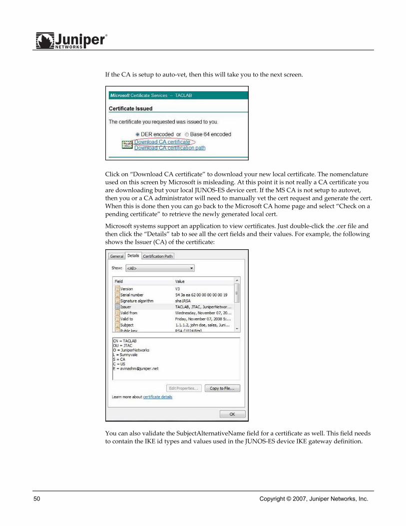
50 Copyright © 2007, Juniper Networks, Inc.
If the CA is setup to auto-vet, then this will take you to the next screen.
Click on “Download CA certificate” to download your new local certificate. The nomenclature used on this screen by Microsoft is misleading. At this point it is not really a CA certificate you are downloading but your local JUNOS-ES device cert. If the MS CA is not setup to autovet, then you or a CA administrator will need to manually vet the cert request and generate the cert. When this is done then you can go back to the Microsoft CA home page and select “Check on a pending certificate” to retrieve the newly generated local cert.
Microsoft systems support an application to view certificates. Just double-click the .cer file and then click the “Details” tab to see all the cert fields and their values. For example, the following shows the Issuer (CA) of the certificate:
You can also validate the SubjectAlternativeName field for a certificate as well. This field needs to contain the IKE id types and values used in the JUNOS-ES device IKE gateway definition.

Copyright © 2007, Juniper Networks, Inc. 51
Another thing to check for is the existence of a CDP. The following shows the CDP field and value. Make sure the hostname can be resolved by the JUNOS-ES device and that it is reachable by the JUNOS-ES device.
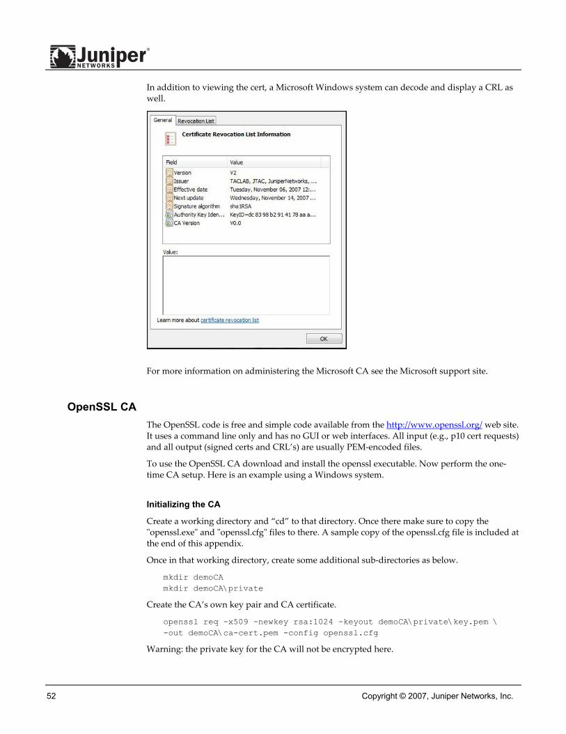
52 Copyright © 2007, Juniper Networks, Inc.
In addition to viewing the cert, a Microsoft Windows system can decode and display a CRL as well.
For more information on administering the Microsoft CA see the Microsoft support site.
OpenSSL CA The OpenSSL code is free and simple code available from the http://www.openssl.org/ web site. It uses a command line only and has no GUI or web interfaces. All input (e.g., p10 cert requests) and all output (signed certs and CRL’s) are usually PEM-encoded files.
To use the OpenSSL CA download and install the openssl executable. Now perform the one-time CA setup. Here is an example using a Windows system.
Initializing the CA
Create a working directory and “cd” to that directory. Once there make sure to copy the ʺopenssl.exeʺ and ʺopenssl.cfgʺ files to there. A sample copy of the openssl.cfg file is included at the end of this appendix.
Once in that working directory, create some additional sub-directories as below.
mkdir demoCA mkdir demoCA\private
Create the CA’s own key pair and CA certificate.
openssl req -x509 -newkey rsa:1024 -keyout demoCA\private\key.pem \ -out demoCA\ca-cert.pem -config openssl.cfg
Warning: the private key for the CA will not be encrypted here.
Copyright © 2007, Juniper Networks, Inc. 53
The ʺca-cert.pemʺ file can be loaded into the JUNOS-ES device as the CA cert.
Now youʹll need to do the following to setup a ʺdatabaseʺ for the certs that will be generated by this CA.
mkdir demoCA\certstore echo 01 > demoCA\ca-cert.srl
Create a new but empty file called index.txt in the demoCA directory.
edit demoCA\index.txt
Now “save” and “exit” leaving it empty. The CA is now initialized.
Generating a Local Cert
For each JUNOS-ES device that needs a cert, set the basic configuration items and certificate request settings as described in this application note.
Once you’ve generated a PKCS10 file, then save that cert request into a file called ”jsNAME.pkcs10”. Then to sign the cert request (PKCS10 file) generated by the JUNOS-ES device, go to the OpenSSL CAʹs working directory (the parent directory of the ʺdemoCAʺ subdir created earlier).
Although the SubjectAlternativeName field information is in the JUNOS-ES deviceʹs PKCS10 cert request, the OpenSSL CA cannot sign it as is. The OpenSSL server will attempt to strip that part out of the cert request. To have the cert populated with a SubjectAlternativeName field you must edit a setting in the openssl.cfg file itself. However, that file must be modified for every cert you sign. Below are steps to edit the openssl.cfg file.
edit openssl.cfg
Search for the SubjectAltName field. Reset the SubjectAltName field to the correct value for this particular JUNOS-ES device cert we are about to sign. For example:
subjectAltName=DNS:ssg5.juniper.net
To create and sign the cert, assuming the cert request from the JUNOS-ES device is in a file called ʺjsNAME.pkcs10ʺ and the cert will get created in a file call ʺjsNAME.cerʺ, issue the command below.
openssl ca -config openssl.cfg -in jsNAME.pkcs10 -out jsNAME.cer
The JUNOS-ES deviceʹs local cert is now the ʺjsNAME.cerʺ file and can be loaded into the JUNOS-ES device. A copy of this certificate is also created in the demoCA\certstore subdirectory with a name of NN.pem where NN is the serial number of this cert.
This cert is in PEM format. To view the cert with the Microsoft cert viewer, the cert will need to be converted to the DER encoding format. To do this edit the jsNAME.cer file. Delete everything except the ----BEGIN/END certificate--- lines and all the data between those lines. This allows Microsoft Windows to decode the file properly to display its contents. The OpenSSL CLI also has the ability to convert the PEM encoded cert to DER encoding. See the OpenSSL documentation for details.
Revoking a Cert and Generating a new CRL
To revoke a particular cert, find the serial number of the cert. For example, to revoke certificate with serial number ʺ01ʺ use the commands below.
54 Copyright © 2007, Juniper Networks, Inc.
openssl ca -config openssl.cfg -revoke demoCA\certstore\01.pem
You may see an error here. If so then manually move the file as below.
mv demoCA\index.txt.new demoCA\index.txt
Next generate the new CRL as below.
openssl ca -config openssl.cfg -gencrl -out crl.crl
The crl.crl file can now be loaded onto the JUNOS-ES device. Load the CA cert, CRL, and local certificate following the same steps as decribed in this application note.
OpenSSL.cfg File Sample ============ # # OpenSSL example configuration file. # This is mostly being used for generation of certificate requests. # # This definition stops the following lines choking if HOME isn't # defined. HOME = . RANDFILE = $ENV::HOME\\.rnd # Extra OBJECT IDENTIFIER info: #oid_file = $ENV::HOME\\.oid oid_section = new_oids # To use this configuration file with the "-extfile" option of the # "openssl x509" utility, name here the section containing the # X.509v3 extensions to use: # extensions = # (Alternatively, use a configuration file that has only # X.509v3 extensions in its main [= default] section.) [ new_oids ] # We can add new OIDs in here for use by 'ca' and 'req'. # Add a simple OID like this: # testoid1=1.2.3.4 # Or use config file substitution like this: # testoid2=${testoid1}.5.6 ################################################################### [ ca ] default_ca = CA_default # The default ca section ################################################################### [ CA_default ] dir = .\\demoCA # Where everything is kept certs = $dir\\certs # Where the issued certs are kept crl_dir = $dir\\crl # Where the issued crl are kept database = $dir\\index.txt # database index file. new_certs_dir = $dir\\certstore # default place for new certs. certificate = $dir\\ca-cert.pem # The CA certificate serial = $dir\\ca-cert.srl # The current serial number crl = $dir\\crl.pem # The current CRL private_key = $dir\\private\\key.pem # The private key RANDFILE = $dir\\private\\.rand # private random number file
Copyright © 2007, Juniper Networks, Inc. 55
x509_extensions = usr_cert # The extentions to add to the cert # Extensions to add to a CRL. Note: Netscape communicator chokes # on V2 CRLs so this is commented out by default to leave a V1 CRL. # crl_extensions = crl_ext default_days = 365 # how long to certify for default_crl_days= 30 # how long before next CRL default_md = md5 # which md to use. preserve = no # keep passed DN ordering # A few difference way of specifying how similar the request should # look. For type CA, the listed attributes must be the same, and # the optional and supplied fields are just that :-) policy = policy_match # For the CA policy [ policy_match ] countryName = optional stateOrProvinceName = optional organizationName = optional organizationalUnitName = optional commonName = supplied emailAddress = optional # For the 'anything' policy # At this point in time, you must list all acceptable 'object' # types. [ policy_anything ] countryName = optional stateOrProvinceName = optional localityName = optional organizationName = optional organizationalUnitName = optional commonName = supplied emailAddress = optional ################################################################### [ req ] default_bits = 1024 default_keyfile = privkey.pem distinguished_name = req_distinguished_name attributes = req_attributes x509_extensions = v3_ca # extensions to add to the self signed cert # Passwords for private keys if not present they will be prompted # for input_password = secret # output_password = secret # This sets a mask for permitted string types of which there are # several options. # # default: PrintableString, T61String, BMPString. # pkix : PrintableString, BMPString. # utf8only: only UTF8Strings. # nombstr : PrintableString, T61String (no BMPStrings or # UTF8Strings). # MASK:XXXX a literal mask value. # WARNING: current versions of Netscape crash on BMPStrings or

56 Copyright © 2007, Juniper Networks, Inc.
UTF8Strings # so use this option with caution! string_mask = nombstr # req_extensions = v3_req # extensions to add to a cert request [ req_distinguished_name ] countryName = Country Name (2 letter code) countryName_default = US countryName_min = 2 countryName_max = 2 stateOrProvinceName = State or Province Name (full name) stateOrProvinceName_default = Illinois localityName = City or local name localityName_default = Chicago 0.organizationName = demo-company.com 0.organizationName_default = netscreen.com # we can do this but it is not needed normally :-) #1.organizationName = Second Organization Name (eg, company) #1.organizationName_default = Sales organizationalUnitName = Org Unit organizationalUnitName_default = CSE commonName = Common Name commonName_default = test-CA commonName_max = 64 emailAddress = Email Address emailAddress_default = [email protected] emailAddress_max = 40 # SET-ex3 = SET extension number 3 [ req_attributes ] challengePassword = secretkey challengePassword_min = 4 challengePassword_max = 20 unstructuredName = juniper.net [ usr_cert ] # These extensions are added when 'ca' signs a request. # This goes against PKIX guidelines. Some CAs do this and some # software requires this to avoid interpreting an end user # certificate as a CA. basicConstraints=CA:FALSE # Here are some examples of the usage of nsCertType. If it is # omitted the certificate can be used for anything *except* object # signing. This is OK for an SSL server. # # nsCertType = server # For an object signing certificate this would be used. # nsCertType = objsign # For normal client use this is typical # # nsCertType = client, email # # and for everything including object signing: # nsCertType = client, email, objsign # # This is typical in keyUsage for a client certificate.

Copyright © 2007, Juniper Networks, Inc. 57
# keyUsage = nonRepudiation, digitalSignature, keyEncipherment # This will be displayed in Netscape's comment listbox. nsComment = "OpenSSL Generated Certificate" # PKIX recommendations harmless if included in all certificates. subjectKeyIdentifier=hash authorityKeyIdentifier=keyid,issuer:always # This stuff is for subjectAltName and issuerAltname. # Import the email address. # subjectAltName=email:copy subjectAltName=DNS:ssg5.juniper.net # Copy subject details # issuerAltName=issuer:copy #nsCaRevocationUrl = http://www.domain.dom/ca-crl.pem #nsBaseUrl #nsRevocationUrl #nsRenewalUrl #nsCaPolicyUrl #nsSslServerName [ v3_req ] # Extensions to add to a certificate request basicConstraints = CA:FALSE keyUsage = nonRepudiation, digitalSignature, keyEncipherment [ v3_ca ] # Extensions for a typical CA # PKIX recommendation. subjectKeyIdentifier=hash authorityKeyIdentifier=keyid:always,issuer:always # This is what PKIX recommends but some broken software chokes on # critical extensions. #basicConstraints = critical,CA:true # So we do this instead. basicConstraints = CA:true # Key usage: this is typical for a CA cert. However since it will # prevent it being used as a test self-signed cert it is best # left out by default. # keyUsage = cRLSign, keyCertSign # Some might want this also # nsCertType = sslCA, emailCA # Include email address in subject alt name: a PKIX recommendation # subjectAltName=email:copy # Copy issuer details # issuerAltName=issuer:copy # DER hex encoding of an extension: beware experts only! # obj=DER:02:03 # Where 'obj' is a standard or added object # You can even override a supported extension: # basicConstraints= critical, DER:30:03:01:01:FF [ crl_ext ] # CRL extensions.

58 Copyright © 2007, Juniper Networks, Inc.
# Only issuerAltName and authorityKeyIdentifier make any sense in a # CRL. # issuerAltName=issuer:copy authorityKeyIdentifier=keyid:always,issuer:always

Copyright © 2007, Juniper Networks, Inc. 59
Appendix C: DOD PKI Usage The US Federal Government (Department of Defense) maintains a PKI used by many entities including the Military.
DOD PKI Introduction
DOD PKI uses a custom PKI solution based on Netscape iPlanet CA server. Although JUNOS-ES does not officially support Netscape iPlanet CA, it does support much of what is required for DoD support. This custom PKI solution has defined its own certificate profiles and security policies that may differ from other CAs.
We need to examine the profile of DOD PKI and determine what is needed to interoperate with DOD PKI. Here is the summary of the features of DOD PKI:
1. The DOD PKI comprises of a three layer Certificate hierarchy. The root CA is “JITC DoD PKI Class 3 Root CA” and the subordinate CA is “JITC DoD PKI Class 3 ID CA”. The subordinate CA issues all end-entity certificates.
2. A server certificate (which the Juniper device acquires) doesn’t have a SubjectAlternativeName extension field. An example is an e-mail certificate, which the NS Remote client acquires, will normally have a SubjectAlternativeName field containing an IKE id type of email.
3. The DN of all DOD PKI certificates will have multiple OU fields. A server certificate issued by DOD PKI will have the DN form of: CN=<server DNS name or IP>, OU=<military/government organization>, OU=PKI, OU=DoD, O=U.S. Government, C=US
4. A user certificate will have the DN form of: 1. Last Name 2. First Name 3. Middle Initial or Name (optional) 4. Generation [Jr., Sr., II, III, etc] (optional) 5. E-mail address 6. Organization (military/government or contractor) 7. City 8. State 9. Country
5. CA certificates can be downloaded from https://idca.nit.disa.mil/GetCAChain.html. It can be downloaded as two separate CA certificates (the root CA and the subordinate CA), or as a single PKCS7 envelop containing both.
6. The Root CRL is updated approximately every 30 days, while the ID CRL is automatically updated every 24 hours. The CRL distribution point is in the CA certificate with attributes of “certificaterevocationlist;binary”. There is no scope or filter defined in the LDAP URL.

60 Copyright © 2007, Juniper Networks, Inc.
To be able to interoperate with DOD PKI, JUNOS-ES needs to support several things. Below are details on what is needed.
1. Support multiple OU fields to comply with the DN convention of the DOD PKI. JUNOS-ES supports multiple OU entries. This can be specified when generating a PKCS10 cert request by adding multiple OU objects in the subject. Example: request security pki generate-certificate-request certificate-id test hostname
[email protected] subject "CN=idca.nit.disa.mil,OU=DISA,OU=PKI,OU=DoD,
O=U.S. Government,C=US"
This enhancement is not limited to just the OU or O fields of the DN; it applies to all fields including S, L, and Country.
2. Support a CRL LDAP search with default attributes and filters. The LDAP URL of the DOD PKI doesn’t provide filters nor a scope.
3. Support Certificate Chaining and multi-layer CRL verification: the DOK PKI is a two-layer CA hierarchy that is composed of a root CA and subordinate CA.
4. Support DN as peer gateway IKE id type. JUNOS-ES supports distinguished-name as the IKE id of a static or dynamic peer gateway.
5. Allow disabling of CRL-checking for easier debugging view. JUNOS-ES supports this in ca-profile settings.
DOD PKI Setup
Below are instructions for Juniper device IKE configuration based on DOD PKI authentication. This is not a complete list of instructions but more of an addendum to what is already outlined in the body of this application note. Refer to the detailed steps in previous sections.
Generate PKCS10 and retrieve cert
1. The DOD PKI uses a two-tiered hierarchy of CAʹs with the device certs sometimes considered the third or bottom tier. There is a root CA and a couple of sub-ordinate CAʹs. You should retrieve and load the certs for all of these CAʹs in the Juniper device.
2. DOD PKI can only support one CN field in the DN.
3. The DOD PKI requires multiple OU fields. The Juniper device can generate multiple OU fields.
4. You can download the DOD CRL files, or you can automatically use LDAP to retrieve the CRL. If you do use LDAP, make sure you have DNS set on the Juniper device. It will need this to resolve the name of the LDAP server. An easy way to test this is to ping the LDAP server from the Juniper device by name.
5. The CRL file can be larger than 20KB. JUNOS-ES devices support up to 5MB for the CRL.

Copyright © 2007, Juniper Networks, Inc. 61
Set up IKE using the certs
1. Set up the IKE gateway as usual choosing a proposal which uses RSA algorithm.
2. You MUST specify distinguished-name as the IKE id. Since the DOD PKI certs donʹt support the SubjectAlternativeName V3 extensions, the default FQDN (hostname + domain-name) will not work.
3. In the IKE Gateway configuration, select the appropriate preferred local cert and peer CA cert. The Peer Type can be X509 or PKCS7. Try X509 first. If the tunnels don’t work then try the other format.
These steps should be all the changes needed to allow the Juniper device to support IKE tunnels based on DOD-PKI authentication.
Appendix D: Simple Certificate Enrollment Protocol (SCEP) During the normal life cycle of a PKI certificate, certificate expiration can become a challenge from an administration point of view. When a local-certificate expires, the administrator would have to first delete the existing certificate, certificate request and key pair, generate a new key pair, generate a new certificate request, and finally load the newly issued local certificate onto the device.
The SCEP protocol can significantly ease the administrative burden of managing expiration of local certificates by automatically re-enrolling and retrieving new certificates. Furthermore, SCEP can ease the process of the initial certificate request and retrieval process by automatically retrieving the certificate from the CA server (assuming the server supports SCEP).
SCEP is supported beginning with JUNOS with Enhanced Services version 9.0. The steps to configure SCEP are as below. Troubleshooting of SCEP issues can be performed by enabling PKI traceoptions within the security pki hierarchy.
Currently only Microsoft SCEP is supported. Verisign and Entrust is not currently supported but will likely will be in a future release.
Steps to Configure
1. Generate the key-pair. Syntax: request security pki generate-key-pair certificate-id <cert-id> size
<512|1024|2048>
Example: root@host> request security pki generate-key-pair certificate-id mscert1 size
1024
Generated key pair mscert1, key size 1024 bits
2. Configure SCEP server under security pki hierarchy. Syntax: set security pki ca-profile <ca-profile-name> ca-identity <ca-id> enrollment url
<scep-server-url> [retry <count>] [retry-interval <seconds>]

62 Copyright © 2007, Juniper Networks, Inc.
Example: root@host> configure
Entering configuration mode
[edit]
root@host# edit security pki
[edit security pki]
root@host# set ca-profile msca-profile ca-identity msca2000 enrollment url
http://172.19.50.129/certsrv/mscep/mscep.dll retry 3 retry-interval 3
[edit security pki]
root@host# show
ca-profile msca-profile {
ca-identity msca2000;
enrollment {
url http://172.19.50.129/certsrv/mscep/mscep.dll;
retry 3;
retry-interval 3;
}
}
[edit security pki]
root@host# commit and-quit
3. Generate your local certificate by enrolling via SCEP. Syntax: request security pki local-certificate enroll ca-profile <ca-profile-name>
certificate-id <cert-id> challenge-password <challenge-string>
[ip-address <ip-address>|email <email>|domain-name <domain>]
subject "DC=<Domain component>,CN=<Common-Name>,OU=<Organizational-Unit-
name>,O=<Organization-name>,L=<Locality>,ST=<state>,C=<Country>”
Example: root@host> request security pki local-certificate enroll ca-profile msca-profile
certificate-id mscert1 challenge-password "" domain-name tacdomain.com subject
"CN=testuser,OU=Support,O=Juniper Networks,L=Sunnyvale,ST=CA,C=US"
4. If necessary, also enroll your CA certificate. Syntax: request security pki ca-certificate enroll ca-profile <ca-profile-name>
Example: root@host> request security pki ca-certificate enroll ca-profile msca-profile
Fingerprint:
1b:02:cc:cb:0f:d3:14:39:51:aa:0f:ff:52:d3:38:94:b7:11:86:30 (sha1)
90:60:53:c0:74:99:f5:da:53:d0:a0:f3:b0:23:ca:a3 (md5)
Do you want to load the above CA certificate ? [yes,no] (no) yes
CA certificate for profile msca-profile loaded successfully

Copyright © 2007, Juniper Networks, Inc. 63
5. Once you have a certificate loaded, then configure auto-reenrollment. Syntax: set auto-re-enrollment certificate-id <cert-id> ca-profile-name <ca-profile-
name> challenge-password <challenge-string> [re-enroll-trigger-time-percentage
<percent>] [re-generate-keypair]
Example: root@host> configure
Entering configuration mode
[edit]
root@host# edit security pki
[edit security pki]
root@host# set auto-re-enrollment certificate-id mscert1 ca-profile-name msca-
profile challenge-password "" re-enroll-trigger-time-percentage 5 re-generate-
keypair
[edit security pki]
root@host# show
ca-profile msca-profile {
ca-identity msca-id;
enrollment {
url http://172.19.50.129/certsrv/mscep/mscep.dll;
retry 3;
retry-interval 3;
}
}
auto-re-enrollment {
certificate-id mscert1 {
ca-profile-name msca-profile;
challenge-password "$9$jx"; ## SECRET-DATA
re-enroll-trigger-time-percentage 5;
re-generate-keypair;
}
}
[edit security pki]
root@host# commit and-quit
Copyright © 2007, Juniper Networks, Inc. All rights reserved. Juniper Networks and the Juniper Networks logo are registered trademarks of Juniper Networks, Inc. in the United States and other countries. All other trademarks, service marks, registered trademarks, or registered service marks in this document are the property of Juniper Networks or their respective owners. All specifications are subject to change without notice. Juniper Networks assumes no responsibility for any inaccuracies in this document or for any obligation to update information in this document. Juniper Networks reserves the right to change, modify, transfer, or otherwise revise this publication without notice.