june, 2020 elantra (hd) elantra technical service bulletin
TRANSCRIPT
Circulate To: General Manager, Service Manager, Parts Manager, Warranty Manager, Service Advisors, Technicians, Body Shop Manager, Fleet Repair
Technical Service Bulletin
GROUP NUMBER RECALL 20-01-017H-1
DATE MODEL(S) JUNE, 2020 ELANTRA (HD)
ELANTRA TOURING (FD)
SANTA FE (CM) ENTOURAGE (EP)
SUBJECT: 2007-2010 ELANTRA (HD), 2009-2011 ELANTRA TOURING (FD),
2007 SANTA FE (CM) AND 2007-2008 ENTOURAGE (EP) PCB RELAY KIT INSTALLATION (RECALL CAMPAIGN 188)
This TSB supersedes TSB# 20-01-017H, adding procedures and parts for Santa Fe (CM) and Entourage (EP) vehicles.
Description: Moisture may enter the ABS electrical system of certain Elantra (HD), Elantra Touring (FD), Santa Fe (CM) and Entourage (EP) vehicles. Over time, the moisture can cause a short circuit. If a short circuit occurs inside the ABS module, there could be an increased risk of an engine compartment fire. This bulletin describes the procedure to install a relay into the ABS module electrical circuit.
Applicable Vehicles: Certain 2007-2010MY Elantra (HD) and 2009-2011MY, Elantra Touring (FD), 2007-2008MY Entourage (EP) and 2007MY Santa Fe (CM) vehicles produced by Hyundai Motor Company Korea (VIN beginning with a “K”)
*** Retail Vehicles *** Dealers must perform this Recall Campaign whenever an affected vehicle is in the shop for any maintenance or repair. When a vehicle arrives at the service department, access Hyundai Motor America’s “Vehicle Information (VIS)” screen via WEBDCS to identify open Campaigns.
IMPORTANT

RECALL 188 – PCB RELAY BLOCK INSTALLATION
TSB #:20-01-017H-1 Page 2 of 14
SUBJECT:
SUBJECT:
Parts Information:
MODEL PART NAME
FIGURE / PART NUMBER QTY.
Elantra (HD)
Elantra Touring
(FD)
PCB Relay
Kit
(1) Junction Box Upper Cover (2) Extension Wire (3) Label (4) Rubber Packing (5) Fuse Bolts (6) PCB Relay Block
1 91940-2H001-QQH
Santa Fe (CM)
PCB Relay
Kit
(1) Junction Box Upper Cover (2) Extension Wire (3) Fuse Bolts (4) Rubber Packing (5) MIDI Fuse (6) PCB
1
91940-2B005-QQH
Entourage (EP)
PCB Relay
Kit
(1) Junction Box Upper Cover (2) PCB (3) Extension Wire 1
91940-4D001-QQH
1
2 3
4
5
6
1
2
4
3
5
6
1
3
2
RECALL 188 – PCB RELAY BLOCK INSTALLATION
TSB #:20-01-017H-1 Page 3 of 14
SUBJECT:
SUBJECT:
Model Op. Code Operation Op. Time Causal Part No.
Nature Code
Cause Code
Elantra (HD) Elantra Touring (FD) 01D010R0
PCB Relay Kit
Installation 0.3 M/H
91940-2H001-QQH
I11 ZZ3 Santa Fe (CM) 01D010R1 91940-2B005-QQH
Entourage (EP) 01D010R2 91940-4D001-QQH
NOTE 1: Submit Claim on Campaign Claim Entry Screen NOTE 2: If a part is found in need of replacement while performing Recall 188 and the affected part is still under warranty, submit a separate claim using the same Repair Order. If the affected part is out of warranty submit a Prior Approval Request for goodwill consideration prior to performing the work. Service Procedure: Elantra (HD)/Elantra Touring (FD) 1. If applicable, record the customer’s radio
preset stations.
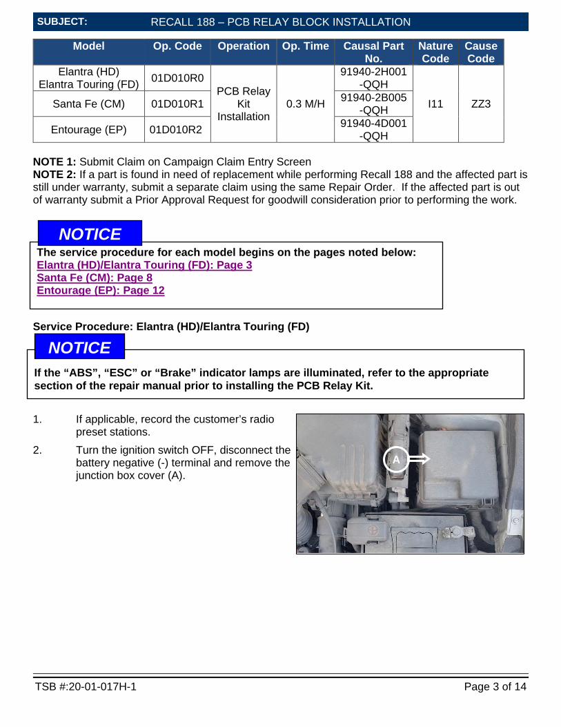
2. Turn the ignition switch OFF, disconnect the battery negative (-) terminal and remove the junction box cover (A).
A
The service procedure for each model begins on the pages noted below: Elantra (HD)/Elantra Touring (FD): Page 3 Santa Fe (CM): Page 8 Entourage (EP): Page 12
NOTICE
If the “ABS”, “ESC” or “Brake” indicator lamps are illuminated, refer to the appropriate section of the repair manual prior to installing the PCB Relay Kit.
NOTICE
RECALL 188 – PCB RELAY BLOCK INSTALLATION
TSB #:20-01-017H-1 Page 4 of 14
SUBJECT:
SUBJECT:
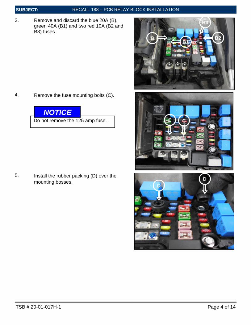
3. Remove and discard the blue 20A (B), green 40A (B1) and two red 10A (B2 and B3) fuses.
4. Remove the fuse mounting bolts (C).
5. Install the rubber packing (D) over the
mounting bosses.
B B1
B2
B3
C C
D D
Do not remove the 125 amp fuse. NOTICE
RECALL 188 – PCB RELAY BLOCK INSTALLATION
TSB #:20-01-017H-1 Page 5 of 14
SUBJECT:
SUBJECT:
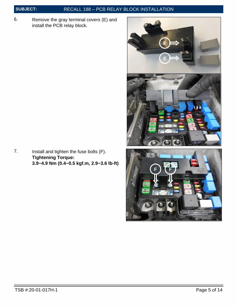
6. Remove the gray terminal covers (E) and install the PCB relay block.
7. Install and tighten the fuse bolts (F).
Tightening Torque: 3.9~4.9 Nm (0.4~0.5 kgf.m, 2.9~3.6 lb-ft)
E
F F
E
RECALL 188 – PCB RELAY BLOCK INSTALLATION
TSB #:20-01-017H-1 Page 6 of 14
SUBJECT:
SUBJECT:
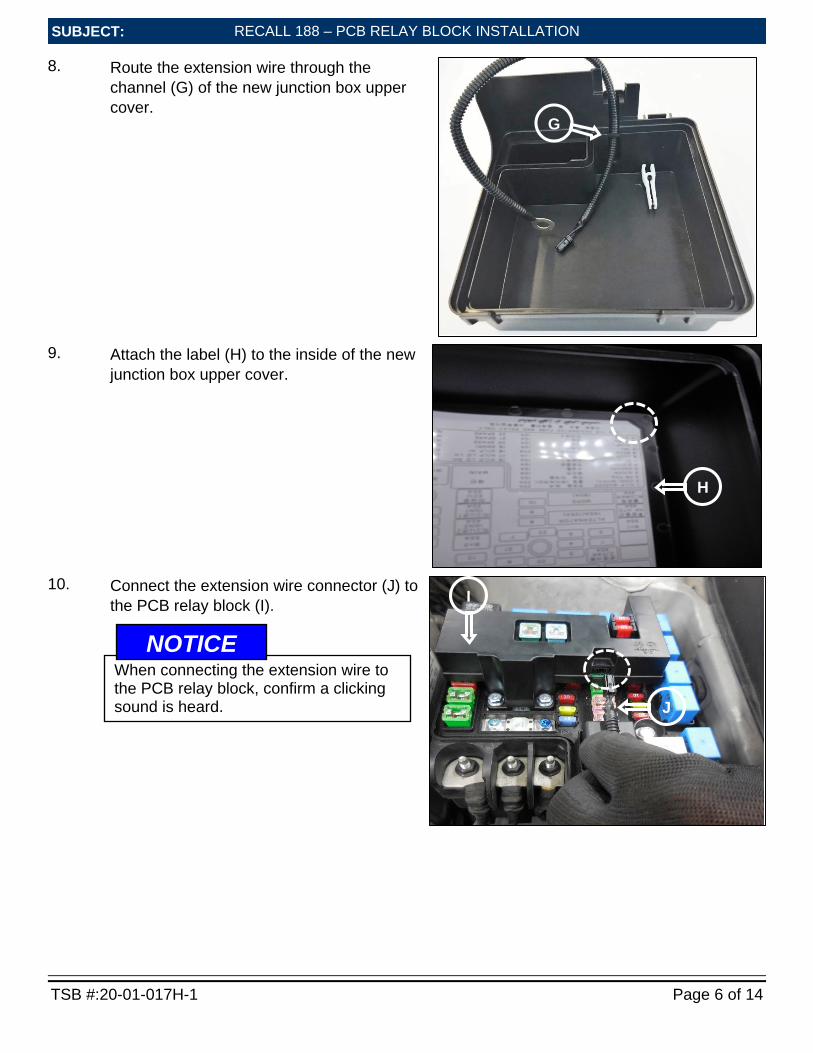
8. Route the extension wire through the channel (G) of the new junction box upper cover.
9. Attach the label (H) to the inside of the new
junction box upper cover.
10. Connect the extension wire connector (J) to
the PCB relay block (I).
I
J
When connecting the extension wire to the PCB relay block, confirm a clicking sound is heard.
NOTICE
G
H
RECALL 188 – PCB RELAY BLOCK INSTALLATION
TSB #:20-01-017H-1 Page 7 of 14
SUBJECT:
SUBJECT:
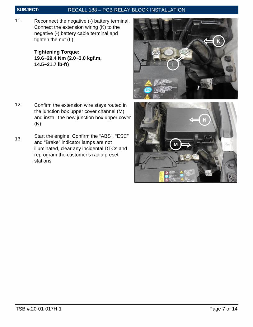
11. Reconnect the negative (-) battery terminal. Connect the extension wiring (K) to the negative (-) battery cable terminal and tighten the nut (L). Tightening Torque: 19.6~29.4 Nm (2.0~3.0 kgf.m, 14.5~21.7 lb-ft)
12. 13.
Confirm the extension wire stays routed in the junction box upper cover channel (M) and install the new junction box upper cover (N). Start the engine. Confirm the “ABS”, “ESC” and “Brake” indicator lamps are not illuminated, clear any incidental DTCs and reprogram the customer’s radio preset stations.
L
K
N
M

RECALL 188 – PCB RELAY BLOCK INSTALLATION
TSB #:20-01-017H-1 Page 8 of 14
SUBJECT:
SUBJECT:
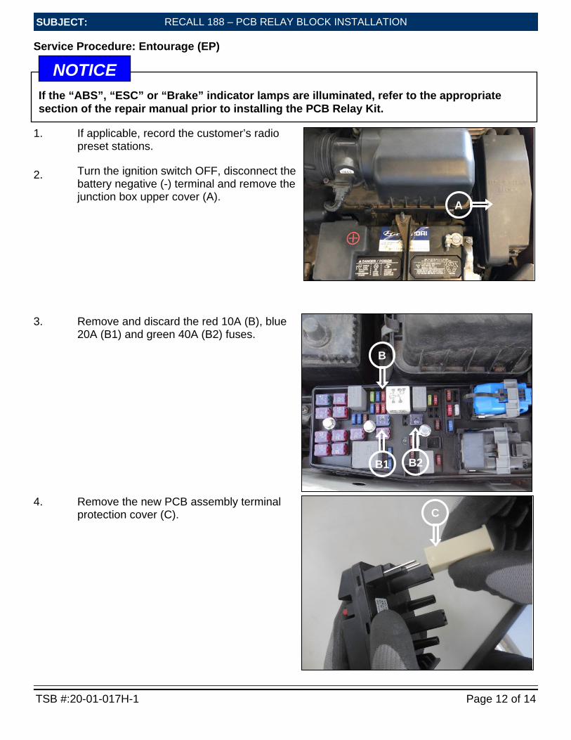
Service Procedure: Santa Fe (CM)
1. If applicable, record the customer’s radio preset stations.
2. Turn the ignition switch OFF, disconnect the battery negative (-) terminal and remove the junction box upper cover (A).
3. Remove and discard the red 10A (B), green 40A (B1) and blue 20A (B2) fuses.
4. Remove the two bolts from the MIDI fuse (C).
A
B
B1 B2
C Not all applications will have a MIDI fuse in this location.
NOTICE
C
If the “ABS”, “ESC” or “Brake” indicator lamps are illuminated, refer to the appropriate section of the repair manual prior to installing the PCB Relay Kit.
NOTICE
RECALL 188 – PCB RELAY BLOCK INSTALLATION
TSB #:20-01-017H-1 Page 9 of 14
SUBJECT:
SUBJECT:
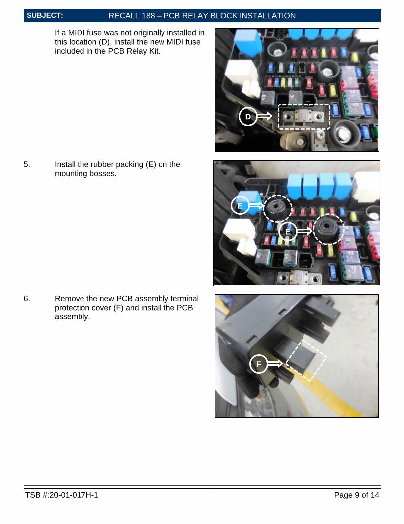
If a MIDI fuse was not originally installed in this location (D), install the new MIDI fuse included in the PCB Relay Kit.
5. Install the rubber packing (E) on the mounting bosses.
6. Remove the new PCB assembly terminal protection cover (F) and install the PCB assembly.
E
E
F
D

RECALL 188 – PCB RELAY BLOCK INSTALLATION
TSB #:20-01-017H-1 Page 10 of 14
SUBJECT:
SUBJECT:
7. Install and tighten the new PCB fuse bolts (I). Tightening Torque: 3.9 ~ 4.9 Nm (0.4 ~ 0.5 kgf. m, 2.9 ~ 3.6 lb-ft)
8. Remove the body ground bolt and reinstall it with the extension wire terminal (J) attached. Tightening Torque: 10.7 ~ 13.7 Nm (1.1 ~ 1.4 kgf.m, 7.9 ~ 10.1 lb-ft)
G
H
PCB terminal (G) is seated in the junction box where the 10A fuse was removed (H).
NOTICE
I I
J

RECALL 188 – PCB RELAY BLOCK INSTALLATION
TSB #:20-01-017H-1 Page 11 of 14
SUBJECT:
SUBJECT:
9. Connect the extension wire connector (K) to the PCB assembly (L), and reconnect the negative (-) battery terminal.
10. Install the new junction box upper cover (M).
11. Start the engine. Confirm the “ABS”, “ESC” and “Brake” indicator lamps are not illuminated, clear any incidental DTCs and reprogram the customer’s radio preset stations.
L
When connecting the extension wire to the PCB relay block, confirm a clicking sound is heard.
NOTICE K
M
RECALL 188 – PCB RELAY BLOCK INSTALLATION
TSB #:20-01-017H-1 Page 12 of 14
SUBJECT:
SUBJECT:
Service Procedure: Entourage (EP)
1. If applicable, record the customer’s radio preset stations. Turn the ignition switch OFF, disconnect the battery negative (-) terminal and remove the junction box upper cover (A).
2.
3. Remove and discard the red 10A (B), blue 20A (B1) and green 40A (B2) fuses.
4. Remove the new PCB assembly terminal protection cover (C).
B
B2 B1
C
A
If the “ABS”, “ESC” or “Brake” indicator lamps are illuminated, refer to the appropriate section of the repair manual prior to installing the PCB Relay Kit.
NOTICE

RECALL 188 – PCB RELAY BLOCK INSTALLATION
TSB #:20-01-017H-1 Page 13 of 14
SUBJECT:
SUBJECT:
5. Connect the extension wire connector (D) to the PCB assembly (E) and install the PCB relay block.
6. Route the extension wire (F) around the rear of the junction box to the battery in the gap (G) between the air cleaner housing and the junction box. The extension wire should be routed beside the BCM-FE wire harness (H) to prevent it being pinched by the junction box upper cover.
D
When connecting the extension wire to the PCB relay block, confirm a clicking sound is heard.
NOTICE
E
G F
H
RECALL 188 – PCB RELAY BLOCK INSTALLATION
TSB #:20-01-017H-1 Page 14 of 14
SUBJECT:
SUBJECT:
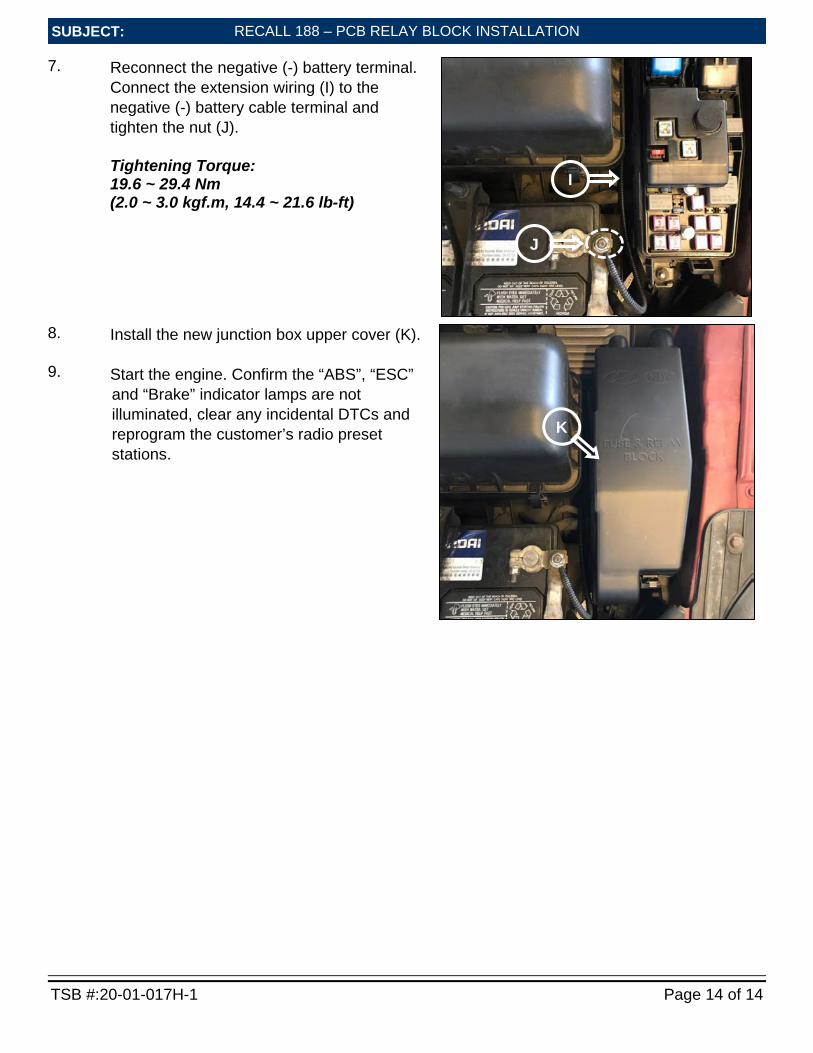
7. Reconnect the negative (-) battery terminal. Connect the extension wiring (I) to the negative (-) battery cable terminal and tighten the nut (J). Tightening Torque: 19.6 ~ 29.4 Nm (2.0 ~ 3.0 kgf.m, 14.4 ~ 21.6 lb-ft)
8. Install the new junction box upper cover (K).
Start the engine. Confirm the “ABS”, “ESC” and “Brake” indicator lamps are not illuminated, clear any incidental DTCs and reprogram the customer’s radio preset stations.
9.
K
I
J