june 1998 alerts - federal aviation administration · 2005-06-22 · june 1998 faa ac 43-16 1 u.s....
TRANSCRIPT
General AviationAirworthinessAlerts
AC No. 43-16
ALERT NO. 239JUNE 1998
Improve Reliability-Interchange ServiceExperience
A LER TS
Contents of this publication are informational only. Due to the need for extensive distribution of this publication,only one copy is provided to an addressee; however, this publication may be duplicated.
CONTENTS
AIRPLANES
BEECH................................................................................................................................... 1BELLANCA ........................................................................................................................... 3CESSNA ................................................................................................................................. 4MOONEY ............................................................................................................................... 8PIPER .................................................................................................................................... 8
HELICOPTERS
BELL .................................................................................................................................... 13McDONNELL DOUGLAS ................................................................................................... 14ROBINSON .......................................................................................................................... 15
AMATEUR, EXPERIMENTAL, AND SPORT AIRCRAFT
LONG EZ.............................................................................................................................. 15PITTS ................................................................................................................................... 16REVOLUTION..................................................................................................................... 16SONERAI ............................................................................................................................. 16
POWERPLANTS AND PROPELLERS
McCAULEY ......................................................................................................................... 17
ACCESSORIES
AEROBATIC CABIN DOOR HINGE ................................................................................. 17
AIR NOTES
SAFETY RECOMMENDATION 97.149............................................................................. 19INSPECTION AND CARE OF LANDING GEAR SYSTEMS .......................................... 19AIRWORTHINESS DIRECTIVES (AD’S) ISSUED IN APRIL 1998 ............................... 20IF YOU WANT TO CONTACT US ..................................................................................... 21SUSPECTED UNAPPROVED PART (SUP) SEMINAR................................................... 22FAA FORM 8010-4, MALFUNCTION OR DEFECT REPORT ........................................ 23SUBSCRIPTION REQUEST FORM .................................................................................. 24
June 1998 FAA AC 43-16
1
U.S. DEPARTMENT OF TRANSPORTATION
FEDERAL AVIATION ADMINISTRATION
WASHINGTON, DC 20590
GENERAL AVIATION AIRWORTHINESS ALERTS
The General Aviation Airworthiness Alerts provide a common communication channel through which the aviation communitycan economically interchange service experience and thereby cooperate in the improvement of aeronautical product durability,reliability, and safety. This publication is prepared from information submitted by those of you who operate and maintain civilaeronautical products. The contents include items that have been reported as significant, but which have not been evaluated fullyby the time the material went to press. As additional facts such as cause and corrective action are identified, the data will be publishedin subsequent issues of the Alerts. This procedure gives Alerts’ readers prompt notice of conditions reported via Malfunction orDefect Reports. Your comments and suggestions for improvement are always welcome. Send to: FAA; ATTN: DesigneeStandardization Branch (AFS-640); P.O. Box 25082; Oklahoma City, OK 73125-5029.
AIRPLANES
BEECH
Beech; Model BE-76; Duchess; Propeller Lever Detent Malfunction; ATA 7603
During a training flight, the left propeller was feathered. Initially, the pilot was unable toreturn the propeller lever (P/N 105-940000-11) to the forward position. Extra force was requiredto move the lever, and when it moved, the pilot heard a loud snap. The propeller came out offeather, and a safe, uneventful landing was made.
Upon investigation, it was found that both propeller levers could ride up and over the featherdetent spring (P/N 105-940021-3). The instrument panel cross-brace assembly that the detentspring attaches to was deformed. This allowed the spring position to shift and the propellerlevers to ride over the spring. The levers would then jam in the feathered position.
To ensure that this does not occur, special attention should be given during routine inspections.The propeller levers should be pulled back into the feather position and checked for properdetent position.
Part total time was not reported.
FAA AC 43-16 June 1998
2
Beech; Model BE36TC; Bonanza; Fuel Gauge Transmitter Error; ATA 2842
The owner of the aircraft reported fuel quantity indication fluctuation during cruise at 9,000feet.
The aircraft was inspected and a “ground run” conducted, but no problem was discovered. Whenthe aircraft was flown again, a preflight inspection of the gauges showed 35 gallons of fuel in theright tank and 15 gallons in the left tank.
The runup, takeoff, and climb to 10,000 feet were normal, and the problem could not beduplicated. The pilot made a spiraling, steep descent to the left. After ten 360-degree turns, thepilot made a shallow descent; and within 30 seconds the engine quit. The emergency boost pumpwas turned on, and the left tank was selected along with the high boost pump setting. The pilotswitched back to the right tank which still showed 35 gallons, and the best glide speed wasattained. With this noseup attitude, the engine power resumed for 4 to 5 seconds, and then itquit again. Intermittent power suggested a fuel problem with the right tank. The left tank wasselected again; the engine was restarted and ran normally.
After landing, the aircraft was taxied to maintenance, the fuel valve was turned to the righttank, and the engine quit. Maintenance began defueling the right tank and found only 1 quart offuel remaining. An incorrect fuel quantity transmitter (P/N 58-380001-13) installed in the rightwing was replaced with the correct transmitter (P/N 58-380001-15). Maintenance alsodiscovered the sight gauge (P/N 002-381002-15) was stuck on 35 gallons.
In many cases, quantity indicators prove less than dependable. In this instance, the electrictransmitter was incorrect and inoperative; and the mechanical sight gauge was stuck on 35gallons.
Since inadvertent fuel starvation is frequently the cause of aircraft accidents, pilot/ownereducation and extra precaution is paramount. The best instrumentation is no substitute forproperly-maintained fueling logs, an intimate knowledge of your aircraft’s hourly fuelconsumption, and a visual check down the filler neck before each flight.
Part total time-1,900.9 hours.
Beech; Model B-100; King Air; Combustion Chamber Failure; ATA 7240
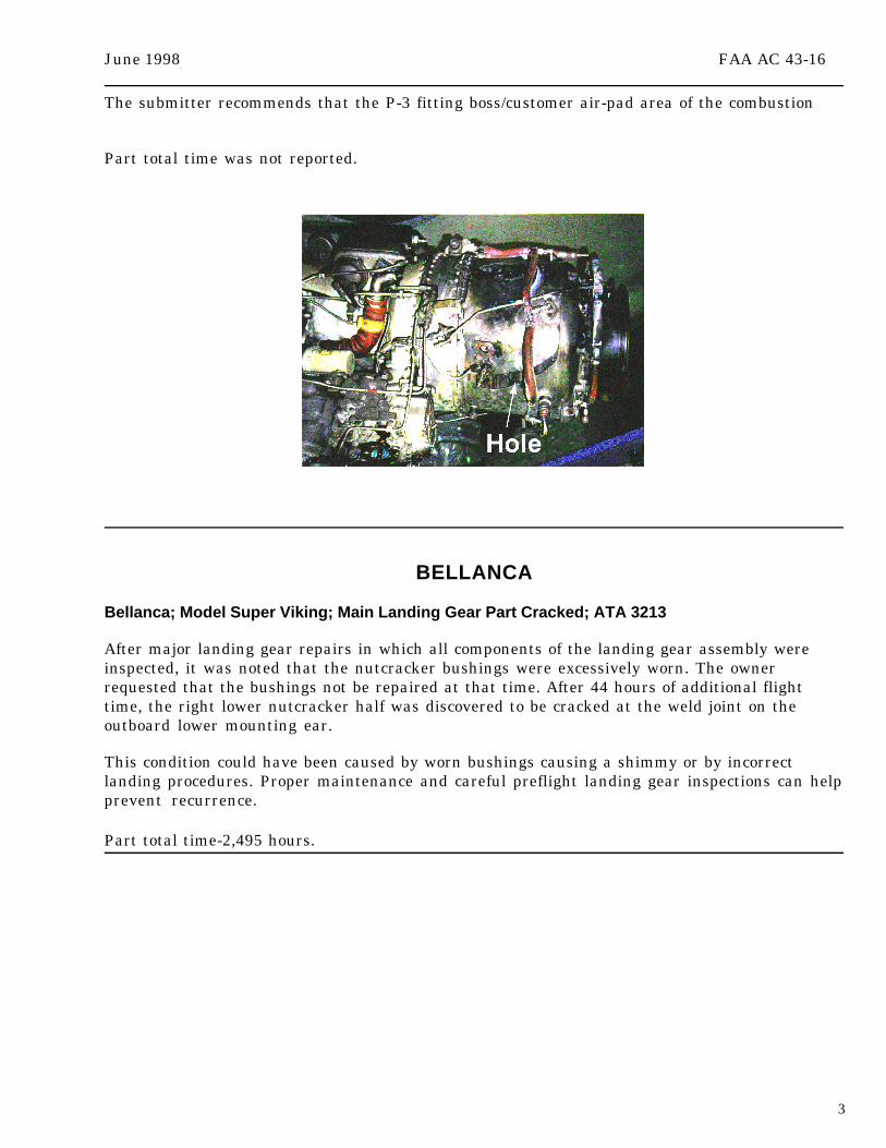
During a normal takeoff while passing through approximately 80 knots, the pilot of a King AirB-l00 heard a “poof” sound. The pilot looked at the left engine nacelle and noticed the cowlingpaint was discolored, and the oil filler door was open. The pilot reduced the engine power,aborted the takeoff, and accomplished engine-emergency shutdown procedures.
Investigation of the aircraft determined that the left engine combustion case (plenum) hadfailed. The plenum (P/N 893973-5) had failed near the P-3 fitting boss and caused minor damageto the engine compartment’s surrounding area. (Refer to the following illustration.)
June 1998 FAA AC 43-16
3
The submitter recommends that the P-3 fitting boss/customer air-pad area of the combustion
Part total time was not reported.
BELLANCA
Bellanca; Model Super Viking; Main Landing Gear Part Cracked; ATA 3213
After major landing gear repairs in which all components of the landing gear assembly wereinspected, it was noted that the nutcracker bushings were excessively worn. The ownerrequested that the bushings not be repaired at that time. After 44 hours of additional flighttime, the right lower nutcracker half was discovered to be cracked at the weld joint on theoutboard lower mounting ear.
This condition could have been caused by worn bushings causing a shimmy or by incorrectlanding procedures. Proper maintenance and careful preflight landing gear inspections can helpprevent recurrence.
Part total time-2,495 hours.

FAA AC 43-16 June 1998
4
CESSNA
Cessna; Model 172N; Skyhawk; Brake Disc Cracks; ATA 3242
Three cracks were discovered by visual inspection of the main landing gear brake disc(Cleveland Brakes, S/N not provided). The cracks radiated across the disc and extendedcompletely through the disc. (Refer to the following illustration.)
The submitter stated that this is the third cracked disc that he has found this year.
Part total time was not reported.
Cessna; Model 172R; Skyhawk; Loose Rocker Shaft; ATA 8530
Due to a rough running engine, the pilot made a precautionary landing. A technician inspectedthe aircraft and discovered that the number 3 cylinder was dead. The valve cover was removedto find the intake and exhaust rocker shaft loose and one retaining nut inside the valve cover.The aircraft had been returned to service approximately 2 hours earlier. The log book showedthat all of the push rod seals were replaced due to oil leaks. The oil seals were all replaced; butupon reinstallation of the rocker shaft, the mechanic used star washers to secure the plain nutsin place. The Continental engine manuals call for a nut lock (P/N 50186). Twenty-four new lockswere installed on all rocker shaft retaining nuts and “crimp locked” as required.
In this case, the problem was found and corrected with no harm done. However, this is a goodexample of why substitution of parts should not be done. Under different circumstances, thissame failure could have resulted in a very serious situation.
Part total time was not reported.

June 1998 FAA AC 43-16
5
Cessna; Model 182N; Skylane; Missing Carburetor Drain Plug; ATA 7322
A few minutes after takeoff, on an instrument flight rule (IFR) training flight, the engine beganrunning very rough.
The pilot tried adjusting the mixture, carburetor heat, and throttle but the roughnesscontinued. Shortly thereafter, the pilot noticed that a fire had erupted in the enginecompartment. While the fire was still burning, the pilot returned to the airport and made a safelanding. After touchdown, the fuel valve was closed. With the aid of airport security, the firewas extinguished with a portable fire extinguisher.
The engine was allowed to cool, the cowling was removed, and an inspection revealed that thedrain plug for the carburetor bowl was missing. No evidence of safety wire was found on thedrilled safety wire hole next to the drain plug. Apparently the plug had not been properlytorqued or safety wired.
Part total time-1,752 hours.
Cessna; Model T206; Horizontal Stabilizer Rib Cracks; ATA 5511
During an annual inspection a clicking noise was heard while pressing the leading edge of thehorizontal stabilizer.
Closer inspection revealed that several ribs were cracked on both the left and right sides of thestabilizer (P/N 1232600-29). This aircraft also had a bent rib (P/N 1232105-1).
The submitter stated that this is the third Cessna T206 he has seen with cracked leading edgeribs and suggested that years of pushing on the tail section during ground handling may havecontributed to this condition.
Part total time–3,197 hours.
Cessna; Model 335; Exhaust Stack Damage; ATA 7800
During a routine engine change, two large holes were found in the left engine inboard exhauststack. This was apparently caused by contact with the heat shields that were mounted above theelbow because the heat shields also had holes in them and were burned by the escaping exhaustgases.
The main wire bundle containing all necessary wiring for the left engine is routed directlyabove the heat shields. Several wires showed signs of heat damage to the insulation, and onewire was burned completely in half.
If this condition were allowed to continue, control of all electrical components (starter,magnetos, alternator, etc.) on the left engine could have been lost. Quite possibly an engine firecould have resulted, and with nacelle fuel tanks located behind the engine, the results couldhave been catastrophic.
Close attention should be paid to this area on both engines due to the routing and constructionof the exhaust system. This area is difficult to inspect; however, removal of the induction aircanister should provide enough access to perform an inspection using a light and mirror.
Part total time-2,780 hours.
FAA AC 43-16 June 1998
6
Cessna; Model 414; Chancellor; Worn Structural Parts; ATA 5300
During an inspection of the nosewheel well substructure, a number of bulkhead cracks, loosebolts, and sheared rivets were found on the stiffeners and T-angles. Doublers (P/N 5213045-3LHand P/N 5213045-2RH) were found cracked at the upper aft corner radius relief cutouts.
The exact cause of the failures could not be determined; however, they may have been caused bylanding or ground handling (or both). The submitter recommends close visual inspection forloose bolts, sheared rivets, and cracks in the substructure every 100 hours.
Part total time–3,709 hours.
Cessna; Model C-550; Citation II; Cabin Door Hinge Assembly Corrosion; ATA 5210
The cabin door was removed to change the bearing assemblies in the door hinge, and corrosiondamage was discovered in the hinge assembly (P/N 5511235-16). Since the hinge was made ofmagnesium, the damaged area could not be removed without compromising the strength of thehinge; therefore, a new assembly was required.
The submitter suspects that the contributing factor to the corrosion was the lack of lubricationin the bearing assembly. Lubrication of this specific part is not listed in the inspection guide(e.g., the lubrication of the landing gear torque links).
Since not having this item listed caused the lubrication to be overlooked, the submitter includedthis item in the guide for lubrication at regular intervals. This should minimize costly partreplacements.
Part total time-4,137 hours.
Cessna; Model 560; Citation V; Starter-Generator Bearing Failure; ATA 2435
The pilot reported the aircraft was vibrating and asked the technician to troubleshoot theproblem.
The technician was in the process of eliminating items that rotate, and was listening to therundown after motoring the engine to 10 percent with the starter. The right starter generatormade an unusual noise upon engine rotation. When the starter was removed, inspectionrevealed that the brush and bearing had failed, and there was excessive play in the shaft. Partof the bearing cage fell out when the starter was turned up on end. An operational check afterinstalling a new starter generator (P/N 9912125-2) confirmed the source of the vibration was theold starter generator.
Cessna Aircraft Service Bulletin 560-80-03 provides information on service which may beneeded on this model starter generator.
Part total time-182 hours.
Cessna; Model 560; Citation V; Main Gear Axle Corrosion; ATA 3213
While performing Phase 1 and Phase 2 inspections on the aircraft, it was discovered that bothmain landing gear axles had corrosion. Item code number A324040 in the Phase 2 inspectionrequires the axle be inspected for presence of primer on the axle and axle adapter where thebrake and brake adapter are located. (Refer to the following illustration.) The axle and axle

June 1998 FAA AC 43-16
7
adapter did not have the required primer on them. As a result, light corrosion had alreadystarted forming. The corrosion was removed and corrosion-resistant epoxy primer was appliedper the Citation Component Maintenance Manual.
The aircraft was delivered in September 1997 and had 151.8 hours at the time of inspection. Thefirst 150 hours had accumulated rather quickly. If it had taken longer to accumulate that time,the corrosion could have possibly been beyond repairable limits.
This is the second time the submitter has found axles without the required primer. The firsttime was on February 5, 1993. This was before the corrosion inspection was required in thePhase 2 inspection. At that time, the submitter found the corrosion while performing a brakechange. Shortly after that, the inspection was added to the Phase 2 inspection. The submitteradds: “The axle should have had the primer applied at the factory. Somehow these main gearassemblies slipped through quality control without the required primer being applied.”
Obviously, quality control should have caught these errors before the aircraft left the factory;however, like all things involving humans, there is a need for redundancy. The watchful eye andtechnical “know how” of properly trained-technicians doing their job well (as in this case) makesthe overall system work well.
Cessna; Model C-560; Citation V; Generators Would Not Parallel; ATA 2435
The pilot reported that the generators would not share the electrical load evenly (parallel).
Inspection revealed that both the starter/generator grounding connections were loose wherethe ground lead attaches to the airframe grounding point on the main engine mount. Minorarcing was noted on the left-hand ground. Both connectors were cleaned and resealed.
This condition apparently resulted from improper torque of the attaching hardware, since thisaircraft was delivered new from the factory in June 1997. Operators of this make and model aircraftshould inspect the ground connectors for proper torque.
Part total time-514 hours.

FAA AC 43-16 June 1998
8
MOONEY
Mooney; Model M20C; Ranger; Seat Track Problem; ATA 5347
The seat adjustment tracks (both left and right seats) were found impacted with dust and cabindebris combined with track lubricant filling the blind holes so that the seat locking pins hadvery little penetration into the seat track. This potential problem was compounded by the factthat seat track holes had begun to show signs of ramp and funnel wear at the top.
The owner-pilot of this aircraft did not experience a seat locking failure, but it was apparentthat half of the holes were close to malfunctioning. The submitter recommends that the holes bechecked and cleaned (if necessary) during every annual inspection.
Part total time-3,289 hours.
Mooney; Model M20J; Broken Steering Horn Shaft; ATA 3251
During a landing roll, the pilot was not able to maintain control of the aircraft. The aircraftexited the side of the runway, hit a runway light, and the nose gear collapsed after passingthrough a drainage ditch.
When repairs were made, the technician discovered that the nose gear and the steering hornshaft (P/N 720095-017) had been broken before this flight. This problem caused the pilot to losecontrol of the nosewheel steering.
The submitter speculates that the failure of the steering horn shaft was caused by exceeding thenose gear travel limits during towing of the aircraft with a tug in ground operation.
Part total time-955 hours.
PIPER
Piper; Model PA18; Super Cub; Frame Corrosion; ATA 5310
An FAA-approved repair station, which rebuilds and repairs Piper PA-18 fuselage frames, hasfound severe corrosion on approximately 35 percent of the fuselages. One problem area is on the5/8-inch vertical tube (P/N 10562-36) that extends from the top longeron, up to the rear wingattach fitting, on the right side at the aft upper door. (Refer to the following illustration.) Thechannel (P/N 12205-5) which is tack welded to this tube, is placed to provide proper clearance ofthe rear upper door. Apparently, trapped moisture behind the channel corrodes the 5/8-inchtube. This is a nearly impossible area to inspect unless the channel is removed. The area, notcovered by the channel, generally remains relatively free of corrosion. The most prevalent areafor corrosion is at the lower end; however, tubes are often corroded the entire length to the rearwing attach fitting.
The tube in question is the only vertical, load-carrying member to the right rear wing attachfitting. If indications of corrosion are found on this tube, the submitter recommends furtherinspection of tubes with like channel-covered surfaces for signs of corrosion.

June 1998 FAA AC 43-16
9
Piper Service Bulletin (SB) No. 819, dated February 1986, pertains to similar problems withPiper Models J-4, J-5, PA-12, and PA-14; however, the Piper Model PA-18 is omitted from thisbulletin.
Recommendation: The channel is a nonstructural part and at replacement of this, or otherchannels, proper breathing and ventilation should be provided. A channel replacement shouldinclude a 3/8-inch hole near the top and bottom. If these channels are to be covered with fabric,the fabric should be patterned and cut to provide ventilation.
Part total time was not reported.
Piper; Model PA22; Colt; Severe Wing Strut Rust; ATA 5700
In December 1996, the struts were inspected in accordance with Airworthiness Directive(AD) 93-10-06 and Service Bulletin (SB) 528D. The aircraft was in compliance with the AD andthe SB.
During the 1997 annual inspection, the owner decided to have all four struts (P/N 85559-2)inspected and modified in accordance with Supplemental Type Certificate (STC) SA 4635NM.The old fork barrel was cut off, and two of the struts were found rusted severely on the inside atthe point where the door catches were mounted. The door catches are mounted nearly halfwayup the length of the strut and are secured with two screws.
The struts had to be condemned, and two new struts were used. The owner, also a holder of anInspection Authorization (IA), stated: “AD 93-10-06 does not specifically address this area ofstruts for inspection. The AD references SB 528D which does not inspect for rust defects aroundthe door catches on the right hand front strut and left hand rear strut.”

FAA AC 43-16 June 1998
10
The submitter suggests that the AD be revised to direct removal of the forks. The interiorshould be cleaned and inspected (using a Borescope) through the entire inside length of thestrut. After the struts are modified, they should be sealed and the door catches secured withoutdrilling holes in the strut.
Part total time-2,500 hours.
Piper; Model PA23-250; Aztec; Main Landing Gear Drag Link Bolt Hole Cracks; ATA 3200
During an annual inspection, cracks were found on the main landing gear drag link fittingsupport tube assemblies. The cracks were located on the right hand inboard and the left andright hand outboard aft mounting bolt holes. Two tube assemblies required replacement and onewas repairable.
The aft mounting bolt nuts are inaccessible on the outboard bolts, and the submitterrecommends that the access holes be fabricated, using approved data, to allow access to checkthe aft bolts’ torque. This should be accomplished at landing gear maintenance, 100-hourinspections, and annual inspections.
Part total time-4,122 hours.
Piper; Model PA30; Twin Comanche; Nosewheel Axle Nut Fell Off; ATA 3222
During normal aircraft operation, the nose gear axle nut (P/N 752-482) worked loose and fell offthe tie bolt (P/N 20854-00). This nut is not torqued to a specific amount, but is torqued just tightenough to remove free play on the bearings. When the nut fell off, the tie bolt was allowed toslide to the side of the nose gear casting. During the next gear cycle, the tie bolt jammed in thewheel well, and the nose gear stuck in the retracted position. The pilot tried to lower thelanding gear without success, and the pilot landed the aircraft with the wheels in the “up”position. No one was injured, and the aircraft sustained minor damage.
The submitter recommends that when the axle tie bolt displays thread wear, it should bereplaced and new lock nuts should be installed.
Part total time-7,300 hours.
Piper; Model PA31; Navajo; Defective Fuel Line; ATA 7310
Fuel stains were discovered on the bottom of the right wing near the wing root. Furtherinspection revealed a leaking fuel line in the right wing root area. The cure date on the fuel linewas the third quarter of 1977. The technician replaced the defective fuel line with a new oneand tested it with the pump on.
The technician recommended that a closer and more frequent inspection of these fuel lines beconducted.
Part total time-5,326 hours.

June 1998 FAA AC 43-16
11
Piper; Model PA31-112; Tomahawk; Water In Fuel; ATA 2810
After takeoff on a training flight, the flight instructor noted a loss of engine power in the climbout. He immediately took control of the aircraft and proceeded to make an emergency landing.
Initiating the emergency procedure at approximately 100 feet above ground level (AGL), theflight instructor directed his student to notify the airport tower that they were making anemergency landing. Total engine power was lost while making the turn to land. Attempting toavoid injury to ground personnel and property, the flight instructor targeted a grassy area toland the aircraft which resulted in the left wingtip touching the ground and receiving minordamage.
On examination, the mechanic discovered water in the left wing fuel tank. Aircraft recordsrevealed that this aircraft had not been operated for 3 days prior to the flight and had beenexposed to heavy rains. It is believed that the fuel caps may not have been completely sealedresulting in rain water seeping into the left wing fuel tank. The left wing fuel tank was selectedfor use during this intended flight.
The aircraft fuel system was purged by the mechanic and returned to service after ahard-landing inspection was accomplished. A followup ramp inspection and a records inspectionwere also conducted.
It can never be emphasized enough as to the importance of sumping the fuel tanks for anypresence of water or condensation in the preflight phase of a flight; especially after the aircraftis exposed to heavy rains. Had the airport environment been less forgiving this may not havehad such a happy ending.
Part total time not reported.
Piper; Model PA31-350; Chieftain; Propeller Governor Failure; ATA 6122
While climbing out after takeoff, the propeller governor failed, and the propeller feathered. Thepilot made an emergency landing, and the aircraft was not damaged.
The governor (Model No. F-8-48L) was inspected, and the technician discovered that an internaloil plug had become loose, jammed the oil pump gears, sheared the governor shaft, and causedtotal failure.
Part total time-1,088 hours.
Piper; PA31-350; Chieftain; Electrical System Defect; ATA 2460
While servicing the aircraft battery, the battery relay was found burned and broken.
The battery system still functioned; however, failure was imminent. Even though the batteryrelay contactor (P/N 455-211) “ear” was broken, it was still able to make contact. Poor contactcaused high resistance which produced enough heat to burn the contactor and the attachedwires. The contactor was manufactured in 1975, and the submitter speculated the failure wasdue to age.
Part total time-4,680 hours.

FAA AC 43-16 June 1998
12
Piper; PA32R-301; Saratoga; Improper Alternator Belt; ATA 2410
After the alternator drive belt broke, it was replaced with an improper belt.
The replacement alternator belt was longer than the proper belt. The extra belt length wascompensated for by adjusting the idler pulley 180 degrees from the correct position. Whenadjusted to this position, the idler pulley and the belt can chaff on the lower engine cowling. Inthis case, a hole was chaffed through the cowling skin. Piper is in the process of revising themaintenance manual to clarify the correct alternator belt and idler pulley position. In themeantime, maintenance personnel should be aware of the potential dangers this problempresents. Use only the correct replacement belt by part number. Also, after installation, checkfor proper clearance between the belt/idler pulley and the lower cowling. The subject of thisarticle applies to PA32R-301 aircraft, serial numbers 3246001 through 3246087.
Part total time not reported.
Piper; PA34-200; Seneca; Pitch Trim Failure; ATA 2731
Information for the following article was submitted by the FAA Aircraft Certification Officelocated in Wichita, Kansas. The information resulted from FAA Safety Recommendation 97.058.
The pilot reported that during a normal landing approach, the stabilator trim becameinoperative. After an uneventful landing, maintenance personnel were summoned.
An investigation revealed that the stabilator trim cable was severely frayed and off of thepulleys at the autopilot electric trim servos. This problem was discussed with Allied Signal,Inc., the manufacturer of the KFC 200 autopilot system. Allied Signal, Inc., proposed amaintenance check of the trim system in accordance with Installation Bulletin (IB) 416, datedJanuary 1998, (P/N 600-19416-0000). This check provided coverage for PA34-200 aircraft whichhad the KFC 200 system installed. It was further suggested that stabilator trim cable slippageand fraying may not be isolated to the KFC 200 system. It was recommended an inspection of allPA34-200 aircraft stabilator trim systems be conducted regardless of the electric trim systeminstalled.
Part total time not reported.
Piper; Model PA46-350P; Malibu Mirage; Improper Trunnion Pin to Bushing Clearance; ATA 3213
During an annual inspection, vertical free play of the right main landing gear trunnion pin tobushing clearance measured .025 inches greater than the left main landing gear.
No tolerance for vertical movement could be found in the aircraft manufacturer’s servicemanual. A new forward and aft bushing was ordered and received from the manufacturer. Whenthe service manual was again consulted for a bushing replacement procedure, none was found.
The aircraft manufacturer’s engineering department was consulted for a procedure.Engineering informed the submitter that they had not anticipated the replacement of thebushing; therefore, no procedure was available. They did say that the bushings were installedwith Loctite 290. The Loctite Corporation was then consulted, and the submitter was told itwould require a temperature of 550 degrees to loosen the Loctite 290 product. The aircraft
June 1998 FAA AC 43-16
13
manufacturer’s engineering department was again consulted for maximum temperatureapplication to the aluminum casting. Engineering personnel approved a maximum temperatureof 350 degrees be applied to the aluminum casting.
Using a digital thermometer and a high temperature heat gun, the casting was heated whilemaintaining a temperature below 350 degrees. An internal jaw puller was used to remove thebushing along with wood blocks to protect the casting. It took two men over 10 hours toaccomplish what would seem to be a simple bushing replacement.
The bushings were obviously made of a softer material than the hardened trunnion pins. Thesubmitter consulted other repair shops, and some of the repair shops stated “peel shims” areused to eliminate this play.
The submitter strongly suggests that the manufacturer develop and publish a method of repairfor this area.
Part total time-330 hours.
HELICOPTERS
BELL
Bell; Model 407; Installation of Cargo Hook Kit; ATA 5345
Information for the following article was furnished by the FAA Rotorcraft Certification Officelocated in Fort Worth, Texas.
Bell Helicopter Textron has issued Alert Service Bulletin (ASB) 407-98-16, datedJanuary 30, 1998. This ASB is applicable to helicopters with the following serialnumbers: 53000 through 53152 and 53154 through 53165. This ASB authorizes the installation ofa cargo hook kit (P/N 206-706-341-109-111). The kit changes the position of the manual cargorelease mechanism to provide clearance between the cargo release handle and the copilot seatbottom cushion. Also, this ASB increases the electrical amperage rating of the system circuitbreaker.
Part total time not applicable.
Bell; Model 407; Vertical Fin Damage; ATA 5533
Information for the following article was furnished by the FAA Rotorcraft Certification Officelocated in Fort Worth, Texas.
Bell Helicopter Textron has issued Alert Service Bulletin (ASB) 407-98-17, dated April 3, 1998.This ASB is applicable to helicopters with the following serial numbers: 53000, 53003 through53066, 53068 through 53138, 53140 through 53173, 53175 through 53178, 53181 through 53192,and 53194 through 53196. Bell Helicopter has found that some vertical fin assemblies(P/N’s 206-020-113-221 and -229) may have damage on the inboard skin caused during
FAA AC 43-16 June 1998
14
production. Such damage reduces skin thickness and can decrease the strength of the verticalfin. Part I of ASB 407-98-17 provides inspection procedures. If damage is found, Part II providesthe corrective actions required.
Part total time not applicable.
McDONNELL DOUGLAS
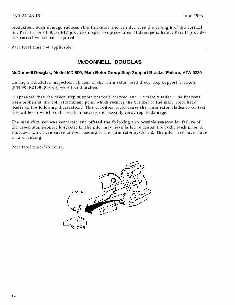
McDonnell Douglas; Model MD 900; Main Rotor Droop Stop Support Bracket Failure; ATA 6220
During a scheduled inspection, all four of the main rotor head droop stop support brackets(P/N 900R2100001-103) were found broken.
It appeared that the droop stop support brackets cracked and ultimately failed. The bracketswere broken at the bolt attachment point which secures the bracket to the main rotor head.(Refer to the following illustration.) This condition could cause the main rotor blades to contactthe tail boom which could result in severe and possibly catastrophic damage.
The manufacturer was contacted and offered the following two possible reasons for failure ofthe droop stop support brackets: 1. The pilot may have failed to center the cyclic stick prior toshutdown which can cause uneven loading of the main rotor system. 2. The pilot may have madea hard landing.
Part total time-778 hours.
June 1998 FAA AC 43-16
15
ROBINSON
Robinson; Model R-22; Mariner; Inspection Requirements; No ATA
The following information was furnished by the Robinson Helicopter Company.
The manufacturer, as well as several FAA Flight Standards District Offices (FSDO’s), haverecently received numerous questions concerning the manufacturer’s “10-year inspection andlimited overhaul requirements.”
Title 14 of the Code of Federal Regulations (14 CFR) part 43, section 43.13(a) requires eachperson performing maintenance on an aircraft to use the current manufacturer’s maintenancemanual or instructions for continued airworthiness prepared by its manufacturer, or otherpractices acceptable to the Administrator.
Sections 43.15(b)(3) and 43.15(b)(4) mandate inspectors of rotorcraft to check specificcomponents and systems in accordance with the maintenance manual or instructions forcontinued airworthiness of the manufacturer concerned.
Therefore, unless otherwise approved by the FAA, an R-22 model helicopter that has been inservice more than 10 years since it was new or since last overhauled is considered unairworthyuntil compliance with the manufacturer’s 10-year requirements have been accomplished.
AMATEUR, EXPERIMENTAL, AND SPORT AIRCRAFT
LONG EZ
Long EZ; Improper Engine Operation; ATA 7322
It was reported that the engine ran rough at lower power settings. The engine used in thisaircraft was a Textron Lycoming, Model O-320.
With the throttle off, the mixture control in idle cutoff, and the fuel boost pump on, fuel pouredfrom the carburetor (P/N MA-45PA). The submitter believed that the carburetor float had failed.Instead of disassembling the carburetor, it was sent to an overhaul shop.
Part total time not reported.
FAA AC 43-16 June 1998
16
PITTS
Pitts; Model S-2A; Engine Failure; ATA 8011
While maneuvering in a flat spin, the engine failed. All attempts to restart the engine failed,and the aircraft crashed.
During the accident investigation, it was found that the starter bendix would not engage, andthe fuel filter had accumulated numerous metal particles. The submitter speculated thatplacing a “Teflon” ring around the “flop tube” (P/N 2-6502-013) would prevent the “flop tube”from scraping the metal and would eliminate metal particles from entering the fuel filter.
Part total time not reported.
REVOLUTION
Revolution; Model Mini 500; Pitch Control Failure; ATA 6710
The pilot intended to make a runway “fly by”; however, as he entered the traffic pattern andmade a base turn, he experienced a 1-to-1 vertical vibration. The pilot notified the control towerthat he intended to land. While decelerating at an altitude of approximately 50 feet, thehelicopter started to veer to the right, and the pilot applied the antitorque pedal. The nose ofthe helicopter went to approximately 50 degrees nosedown, and ground contact was made in anosedown attitude. The pilot was not injured, but the helicopter sustained substantial damage.
During an investigation, it was discovered that a flight control push-pull rod (P/N BA16) hadbecome disconnected from the control yoke “teeter” block (P/N 0026). The attaching hardware(bolt, nut, bushing, and antichafe washer) was found loose inside the lower fuselage skin. Aninspection of the bolt (P/N 0470) and nut (P/N 0434) revealed no evident defects. The self-lockingnut exhibited a lower than usual “drag torque.” The submitter stated: “I was able to run the nutdown on the bolt past the locking feature with my fingers.”
A review of the maintenance records indicated that no maintenance had been performed on thisassembly since original installation.
Part total time-106 hours.
SONERAI
Sonerai; Model II-L; In-Flight Engine Failure; ATA 7414
The engine failed during flight, and all attempts to restart the engine were futile. Thiscondition resulted in an accident which destroyed the aircraft and seriously injured the pilot.
An investigation revealed that the magneto drive coupler, which was keyed to the flywheel, hadbroken. It appeared the coupler broke at the point where it was keyed to the flywheel. Also, thecoupler displayed evidence of a pre-existing crack, or possible casting flaws, at this location.The pilot/owner stated this is a repeat discrepancy, and the aluminum magneto drive coupling
June 1998 FAA AC 43-16
17
usually last about 200 hours of operation. The engine installed in this aircraft was aVolkswagon, Model 2020. The submitter recommended the manufacturer construct this couplingby milling it from high grade aluminum instead of casting the part.
Part total time-130 hours.
POWERPLANTS AND PROPELLERS
McCAULEY
McCauley; Models 71093, 72415, 761101, 780630, and 810915; Possible Incorrect Oil Viscosity;ATA 6114
In accordance with Airworthiness Directive (AD) 91-15-04, all affected systems that have atwo-bladed constant speed propeller with a threaded retention hub are required to be inspectedfor cracks and modified by filling the hub with “dyed” oil. This includes propellers withfeathering capabilities.
It has been discovered that since 1993, a propeller overhaul shop has been filling all McCauleyoil-filled propeller hubs that are installed on reciprocating engines with the wrong weight of oil.An FAA safety recommendation stated that the propeller shop had been misinterpreting theinstructions given in the McCauley service information referenced in AD 91-15-04. Since thisdiscovery, there have been reports of other propeller shops misinterpreting the appropriate oilweight.
It is recommended that all owners and operators of suspect propeller hubs verify that each hubis filled in accordance with McCauley Service Letter 1998-2, dated January 23, 1998. This shouldbe accomplished during the next scheduled maintenance and/or inspection.
ACCESSORIES
AEROBATIC CABIN DOOR HINGE
During postflight inspection, the lower hinge pin on the quick release cabin door assembly ona 1978 Aerobatic Bonanza F33C was noted to be out of normal alignment.
Close inspection revealed the 3/16 inch x 1-3/4 inch hinge pin (P/N 33-420020-1) had fractured atthe machined groove in the middle of the pin and the lower half of the pin had fallen out of thehinge onto the hangar floor. The upper half remained in the hinge.
The pin had failed in flight, but did not fall out in flight due to the side load on both halves.A ground test showed the failed pin did not affect the door release capability. The pin showedno noticeable wear despite being original equipment.

FAA AC 43-16 June 1998
18
The door release pin is fitted horizontally and passes the vertical hinge pin at the machinedgroove. (Refer to the following illustration.) The inflatable door seal, pumped tight at sea level,expands much more at altitude. This expansion presses the door away from the cabin causingthe release pin to bear a side load against the hinge pin, thereby causing the pin to fail.
The inflatable door seal is an after-market product and was installed 253 flight hours ago. Thedoor seal representative said that the door seal had been pumped too tight prior to takeoff.
The submitter has ordered two new pins and will use less pressure in the future.
Part total time-2,302 hours.
June 1998 FAA AC 43-16
19
AIR NOTES
SAFETY RECOMMENDATION 97.149
Cessna Models 172RG, R182, and 210 Series Aircraft; Nose Gear Actuator Downlock PinFailures; ATA 3230
Several incidents have been reported of nose gear collapses on the noted Cessna aircraft whichhave been attributed to failures of the nose landing gear actuator downlock pins. The downlockpins, which are press fit into the actuator bearing end and retained with a roll pin, become looseand crack and/or break at the retaining groove internal to the actuator bearing end. Cracks orbreaks in this location are difficult to detect.
A review by the responsible FAA Aircraft Certification Office revealed the actuator bearing endand downlock pin designs meet the current criteria for expected loads, and the observed failuremode of the pin is inconsistent with design loads applied to an assembly in serviceablecondition. Investigation determined that the probable cause is improper ground handlingduring towing and continued use of the actuator after damage has incurred. Cessna has issuedRecommended Service Bulletin (SEB) 95-20 which details inspection procedures and provides amore robust downlock pin which is less susceptible to failure caused by exceeding the landing,towing, or taxi loads.
The aircraft should be in compliance with this SEB, especially aircraft that are regularlyoperated on rough surfaces or towed by a tug or a tractor. Make sure the nose gearactuator downlock pins are not loose in the bearing end and the actuator bearing end is notdamaged.
INSPECTION AND CARE OF LANDING GEAR SYSTEMS
Recent accidents and incidents have indicated an increase in landing gear problems. Theseproblems include landing gear that would not retract or extend, landing gear collapsing on landing, and part failures causing landing gear to not perform properly. Many factors affect thescope and frequency of landing gear system inspection and maintenance. However, the mostimportant inspection starts with the preflight inspection. Visual inspections of the landing gearare very important whether the landing gear is fixed or retractable. In most cases there arefewer problems with the fixed landing gear, but inspection of the landing gear is still important.
The possibility of system malfunction increases with severe operating conditions such as pilottraining, agricultural operations, and environmental conditions. These conditions may warrantinspections to be performed more frequently to include lubrication and servicing.
Cracks are the foremost area of concern and are very hard to detect. Some indicators couldinclude: chipped paint, soot residue, and corrosion.
Landing gear bolts are an area of concern due to the fact the bolts become worn and bent. Boltscan shear and bolt holes can become worn to allow improper adjustments and alignment of thelanding gear.
FAA AC 43-16 June 1998
20
Improper adjustment or lubrication can also cause malfunctioning, especially in the landinggear retracting mechanisms. Excessive lubrication or the wrong type of lubricant can often beas bad or worse than none at all.
Inspection of the landing gear and all associated hardware is very important. During preflightinspections, it may be necessary to gently rock up and down on the wingtips of the aircraft and observe the landing gear areas for excessive motion which would indicate excessive wear andsecurity of attachment.
It may be necessary to inspect the aircraft structure surrounding the landing gear area toinsure that no damage remains undetected. Forces can be transmitted along affected structuremembers to remote areas where subsequent normal loads can cause failure at a later date.
Landing gear component inspections should include shock absorbers, shock struts, steeringdampers, nose gear assembly, main gear assembly, tailwheel assembly, gear doors, floats, skis,brakes, and wheel assemblies.
AIRWORTHINESS DIRECTIVES (AD’S) ISSUED IN APRIL 1998
98-08-04; Aermacchi S.P.A. Models S.208 and S.208A airplanes - requires inspecting landinggear rod springs.
98-08-06; Aermacchi S.P.A. S.205 Series and Models S.208 and S.208A airplanes - requiresinspecting flight control cables.
98-09-09; Alexander Schleicher ASH-26E sailplanes - requires replacing internal cooling airfan.
98-09-13; Alexander Schleicher ASK21 sailplanes - requires inspecting S-shaped rudder pedaltube.
98-08-29; Alexander Schleicher ASK21 sailplanes - requires removing pages from flight manualand replacing pages concerning spin and stall recovery.
98-08-20; AlliedSignal Bendix/King Model KSA 470 autopilot servo actuators - requiresreplacing autopilot servo actuators.
98-09-08; Avions Pierre Robin Model R3000/160 airplanes - requires inspecting flap controlshaft.
98-08-28; Avions Pierre Robin Model R3000/160 airplanes - requires replacing top bolts in frontwheel fork assembly.
98-09-24; Diamond Aircraft H-36 “Dimona” and HK36R “Super Dimona” sailplanes - requiresinspecting elevator rib area.
98-09-14; Diamond Aircraft HK36TTS and HK36TTC sailplanes - requires inspecting engineturbocharger oil-pressure line for correct banjo jolt.

June 1998 FAA AC 43-16
21
98-06-13; Dornier Luftfahrt Models 228 Series airplanes - requires replacing MLG axleassembly.
98-09-10; Extra Flugzeugbau GmbH Models EA-300 and EA-300S airplanes - requiresinspecting rudder control cables.
98-08-05; Industrie Aeronautiche Meccaniche Model Piaggio P-180 airplanes - requiresinspecting main landing gear.
98-08-26; Pilatus Aircraft Models PC-12 and PC-12/45 - requires installing aluminum bondingbushings.
98-05-06; Pilatus PC-12 airplanes - requires inspecting the elevator for incorrect rivet lengths.
98-07-18; Pilatus PC-12 and PC-12/45 airplanes - requires replacing propeller deicingcontrollers.
98-08-22; Pilatus PC-7 airplanes - requires inspecting elevator and rudder attachment brackets.
98-08-07; Pilatus PC-7 airplanes - requires replacing rudder and elevator pivot arms.
98-08-18; Piper PA-31 Series airplanes - requires inspecting elevator bungee spring for cracks.
98-09-25; Piper PA-31 Series airplanes - requires replacing lower spar splice plate.
98-09-12; Raytheon (Beech) 1900D airplanes - requires inspecting radio switching panel relayPCB.
98-08-21; SOCATA - Groupe Aerospatiale TB10 and TB200 airplanes - requires inspecting wingrear attachment fitting for cracks.
98-08-27; SOCATA - Groupe Aerospatiale TBM700 airplanes - requires modifying left-handfront side lower panel.
98-08-03; Stemme KG Models S10 and S10-V sailplanes - requires replacing horizontalstabilizer rear fittings.
98-07-17; Twin Commander series airplanes - requires inspecting flap system cables.
98-08-19; Twin Commander series airplanes - requires installing access holes.
98-08-25; Twin Commander series airplanes - requires replacing nose landing gear.
IF YOU WANT TO CONTACT US
If you want to contact the staff of this publication we welcome your comments, suggestions, andquestions. Also, you may use any of the following means of communication to submit reportsconcerning aviation-related occurrences.
FAA AC 43-16 June 1998
22
Editor: Phil Lomax, AFS-640Telephone No.: (405) 954-6487FAX No.: (405) 954-4570 or (405) 954-4748
Internet E-mail address: [email protected]
Mailing address: FAA ATTN: AFS-640 ALERTS P.O. Box 25082 Oklahoma City, OK 73125-5029
AFS-600 HomePage Internet address:
http://www.mmac.jccbi.gov/afs/afs600
Current and back issues of this publication may still be obtained from the FedWorldBulletin Board System (BBS) via the Internet at the following address:
http://www.fedworld.gov/ftp.htm
Please do not hesitate to contact us.
SUSPECTED UNAPPROVED PART (SUP) SEMINAR
As announced in previous editions of the Alerts, the Designee Standardization Branch,AFS-640, is once again presenting the Suspected Unapproved Part (SUP) seminar. A schedule ofthe seminars and information for requesting a SUP seminar in your area can be found below.
Seminar dates will be announced in the Alerts, the Designee Update newsletter, and on theInternet under FedWorld.gov. You may access the FedWorld BBS directly at (703) 321-3339.You may access the Alerts through the Internet, using the Regulatory Support Division,AFS-600, “HomePage” at the following address.
http://www.mmac.jccbi.gov/afs/afs600
The seminar will discuss the following:
1. Introduction to the policy of the Suspected Unapproved Part Program Office, AVR-20.2. What is an approved part/unapproved part? How can approved parts be produced?3. What is a suspected unapproved part?4. How is a suspected unapproved part reported in accordance with FAA Order 8120.10A,Suspected Unapproved Parts Program, and utilizing FAA Form 8120-11, Suspected UnapprovedParts Notification?5. How do you determine the status of parts?6. What is the procurement process?7. How do you use the Internet and FedWorld to find a list of unapproved parts?
June 1998 FAA AC 43-16
23
The cost of this 8-hour seminar will be $60. The seminar may be used for the InspectionAuthorization (IA) renewal training requirement specified in Title 14 of the Code of FederalRegulations (14 CFR) part 65, section 65.93(a)(4).
The seminar is open to the aviation industry. Anyone wishing to attend may telephone(405) 954-0138. Payment is required in advance by using VISA, MasterCard, or a check.When scheduling attendance, please reference “AFS-75.”
SCHEDULE FORSUSPECTED UNAPPROVED PART (SUP) SEMINARS
Seminar No. 1998 Location 759806 Jul 15 Seattle, WA 759807 Jul 8 Anchorage, AK 759808 Aug 5 Ft. Lauderdale, FL 759809 Sep 16 Springfield, IL 759901 Oct 21 Rochester, NY 759902 Nov 18 Wichita, KS
ADDITIONAL SUP seminars will be conducted in Atlantic City, NJ on 6/2/98 and 6/3/98;Minneapolis, MN on 6/16/98 and 6/17/98; and Anniston/Oxford, AL on 8/18/98. You may registerfor the seminar by calling (405) 954-0138. The additional SUP seminar is a 1-day, 8-hour seminarand can be used to meet IA renewal requirements.
If you require additional or special SUP seminars, please write to: FAA;ATTN: Mr. Elmer Hunter (AFS-640); P.O. Box 25082; Oklahoma City, OK 73125. Depending onmanpower and the availability of AFS-640 personnel, the requests for additional SUP seminarsmay be authorized. The cost for the additional SUP seminars is $60 per person. We would like aminimum of 40 attendees for a 1-day seminar and no more than 60 attendees. When the numberof attendees is greater than 70, we will conduct two 1-day seminars. The registration process isthe same as that previously discussed in this article. If you have specific questions regarding anadditional SUP seminar, please contact Mr. Elmer Hunter at (405) 954-4099.
FAA FORM 8010-4, MALFUNCTION OR DEFECT REPORT
For your convenience, FAA Form 8010-4, Malfunction or Defect Report, will be printed in everyissue of this publication.
You may complete the form, fold, staple, and return it to the address printed on the form.(No postage is required.)
FAA AC 43-16 June 1998
24
SUBSCRIPTION REQUEST FORM
For your convenience, a Subscription Request Form for AC 43-16, General AviationAirworthiness Alerts, is printed in every issue.
If you wish to be placed on the distribution list, complete the form, and return it, in a stampedenvelope, to the address shown on the form.
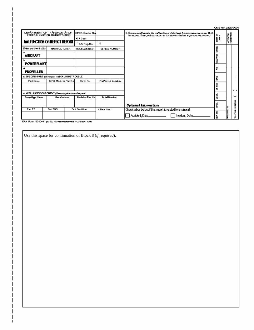
Use this space for continuation of Block 8 (if required).
Federal Aviation AdministrationAFS-640 (Alerts)P.O. Box 25082Oklahoma City, OK 73125-5029
U.S. Departmentof Transpor tationFederal AviationAdministration
Flight Standards ServiceDesignee Standardization BranchP.O. Box 25082Oklahoma City, OK 73125-5029
Official BusinessPenalty for PrIvate Use $300
AFS-640

SUBSCRIPTION REQUEST FORMADVISORY CIRCULAR (AC) 43-16, GENERAL AVIATION AIRWORTHINESS
ALERTS
Please use this request to subscribe to AC 43-16 or to change your address if you are presently on the mailinglist. Once your name has been entered, you will continue to receive this publication until you request your namebe removed or a copy is returned because of an incorrect address.
Because this mailing list is independent of other FAA mailing lists, it is necessary that you notify us when youraddress changes. (Our address is on the following subscription request.) If you are presently receiving thispublication it is NOT necessary to send another subscription request. The following subscription request may beduplicated, as necessary. TELEPHONE REQUESTS WILL ALSO BE ACCEPTED; THE TELEPHONENUMBER IS (405) 954-6487. THE FAX NUMBERS ARE: (405) 954-4748 and/or (405) 954-4570.
AC 43-16 SUBSCRIPTION REQUEST
If you would like to BEGIN receiving AC 43-16, orCHANGE your address, please complete the following:
PLEASE PRINT INFORMATION LEGIBLY,INCLUDE YOUR ZIP CODE, AND THE DATEOF YOUR REQUEST.
NAME:
ADDRESS:
ZIP CODE
DATE:
CIRCLE ONE OF THE FOLLOWING:
1. This is a NEW subscription.
2. This is an ADDRESS CHANGE.
SEND ONLY ONE SUBSCRIPTION REQUEST TOTHE FOLLOWING ADDRESS:
FAA, Regulatory Support DivisionATTN: AFS-640 (Phil Lomax)P.O. Box 25082Oklahoma City, OK 73125-5029
If you require more than one copy of AC 43-16, it may be reproduced.
U.S.Departmentof Transportation
Federal AviationAdministration
Designee Standardization BranchATTN: ALERTS, AFS-640P.O. Box 25082Oklahoma City, OK 73125-5029
AFS-640
Official BusinessPenalty for Private Use $300
BULK MAILPOSTAGE & FEES PAID
Federal AviationAdministration
PERMIT No. G44