jul 2011 - association of clinical cytogeneticists
TRANSCRIPT

High Altitude Platform:
Solution for rainfall attenuation
Reshad Rasul Kazi Student ID: 05310057
Department of Computer Science and Engineering May 2008 BRAC University, Dhaka, Bangladesh

2
DECLARATION
I hereby declare that this thesis is based on the results found by myself. Materials of work found by other researcher are mentioned by reference. This thesis, neither in whole nor in part, has been previously submitted for any degree. Signature of Signature of Supervisor Author

3
ACKNOWLEDGMENTS
Special thanks to Dr. Tarik A Chowdhury and Mrs. Amina Hasan Abedin for taking time out of their busy schedules to help me with my thesis, programs and simulation.

4
Abstract
High Altitude Platform Stations (HAPs) are communication facilities situated at an altitude of 17 to 30 km and at a specified fixed point relative to the Earth. They are mostly solar-powered, unmanned, and remotely operated. These platforms have the capability of carrying multipurpose communications relay payload, which could be in the form of full base station or, in some cases, a simple transponder as is being used in satellite communication systems. HAPs, when fully deployed will have the capability of providing services and applications ranging from broadband wireless access, navigation and positioning systems, remote sensing and weather observation/monitoring systems future generation mobile telephony, digital TV etc. HAPs are also known to be low cost when it comes to its implementation and are expected to be the next big provider of infrastructure for wireless communications. However before, it is implemented different models has to be built to test its performance. Rainfall poses a serious issue to HAP since due to its position rainfall creates the maximum attenuation scenario. So a model is proposed as a solution to this problem .
5
TABLE OF CONTENTS Page TITLE……………..............................................................................................i DECLARATION……………………………………………………………………..ii ACKNOWLEDGEMENTS................................................................................iii ABSTRACT………...........................................................................................iv TABLE OF CONTENTS...........................................................................….....v INTRODUCTION……………………………………………………………………1 CHAPTER I. Present and future telecommunication infrastructures 1.1 Overview………………………………………………………………....2 1.2 HIGH ALTITUDE PLATFORM STATIONS (HAPS)............…....…. 2 1.3 Aerial Platforms………………………………………………………….3 . 1.4 HAPS compared with other systems 1.4.1 Compared with Terrestrial Services………………………..4 1.4.2 Compared with Satellite Services…………………………..4 1.5 Challenges……………………………………………………………….5 CHAPTER II. High Altitude Platform 2.1 HAP Architecture………………………………………………………..6
2.2 Services and Applications……………………………………………...7 2.3 Analysis of Interference in HAPS……………………………………...8 2.4 Antennas for HAPS…………………………………………………......8 2.5 Transmission and Coding techniques for HAP’S…………………….9
CHAPTER III. Rain attenuation and the solution 3.1 Solution.....................................................…………………………...10 3.2 Simulation of HAP system....................................................……....11 3.3 Simulation results……………………………………………………….16 3.4 Simulation Discussion………………………………………………….17 CONCLUSION……………………………………………………………………..18 REFERENCE………………………………………………………………………19

6
Introduction
Wireless communication has stood out as one of the fastest and rapidly growing segment of the communications industry with the ability to provide high-speed, quality and real-time information exchange between portable devices globally. It is defined basically as information transfer over a distance (without the use of known electrical conductors or cables. It is convenient and often less expensive to deploy relative to the fixed network. This technology has in no little way improved the level and standard of our living in this modern age. Research has shown that the worldwide cellular and personal communication subscriber base went beyond half a billion users in the late 2001 and it’s been projected to attain a 2 billion mark which is like 30% of the world population by the end 2008 [3].
A very good example is the design of next generation cellular networks to
facilitate high-speed data communications traffic in addition to voice calls. New technologies and standards are also being implemented to make wireless networks replace fiber optic and/or copper lines between fixed points that are several kilometers apart known as fixed wireless access. In many geographical areas, mobile telephones are the only economical way for providing phone service to subscribers. Base stations are erected quickly and with low cost compared to the cost involved when digging the ground to lay copper especially in some harsh terrain. Mobile telephones are only a small part of the cellular development; many new types of wireless devices are being introduced. Presently, there can’t be said to be a single cellular network. Devices support one or two of a countless number of technologies and generally work within the boundaries of a single operator’s network. New standards for the next generation wireless devices are being developed, which will use higher frequencies to increase capacity and also help eradicate the problem of incompatibility issues, encountered presently.
1

7
1. Present and future telecommunication infrastructures 1.1 Overview
The need to improve on the existing bandwidth available for mobile communication devices and application has made researchers and telecommunication experts delve into more technologies that can provides the needed bandwidth. There has been several works on improving the bandwidth provision from satellite and terrestrial communication [2]. While these are unfolding, there has been several other technologies been looked into that could possibly provide a better bandwidth as required by users of these mobile services. The advantages and disadvantages of terrestrial and satellite systems are well known and have been extensively documented in several works over the years [1]. The drawbacks, in particular, have made engineers continuously search for alternative means of making broadband fixed wireless access available to the ever-growing population of users worldwide. 1.2 HIGH ALTITUDE PLATFORM STATIONS (HAPS)
HAPS are, generally, solar-powered, unmanned, remote-operated and electric motor-propelled aerial platforms held in stationary position, at altitudes between the 17 – 22 Km range above the earth’s surface (stratospheric layer of the atmosphere) [7]. They are somewhat new and are being proposed as means of providing wireless multimedia communications infrastructure for both metropolitan and remote areas. These platforms carry multipurpose communications relay payload, which can range from a complete base station to just a simple transponder, like we have on most satellites.
Due to an interest in aerial platforms and due to advancement in technology, which have yielded better and stronger materials, which are UV resistant and leak-proof to helium, these airships are making their way back to our world.
HAP´s can be considered as being hybrid architecture; they have some zones in common with terrestrial communications, particularly Fixed Wireless Access, but are similar to satellites in terms of power constraints and general network architecture. In a mobile communication context is the fact it could replace or support the terrestrial network, avoiding problems with environmental impact and electromagnetic pollution. Platform design has several constraints related to the applications to achieve: power available for the payload, stability, and maximum transmit power of the transmitters, link availability and so on.
2

8
1.3 Aerial Platforms
The history of HAPS has brought about three distinguishable types of proposed aerial vehicles. These types of platforms can be balloons, aircrafts or airships. They are categorized depending on the way they are managed and maintained. 1. Unmanned Airships: these are mainly balloons and are semi-rigid or non-rigid huge and mainly solar powers balloons, which can be well over 100m in length and could carry a payload of about 800kg or more. This typed of aerial vehicle is aimed at staying up for a period of 5 years or more. 2. Solar-powered unmanned aircraft: These types of aerial vehicles are also known as High Altitude Long Endurance platforms (HALE Platforms) and they make use of Electric motors and propellers as propulsion while during the day, they get power supply from solar cells mounted on their wings and stabilizers which also charge the on-board fuel cells. There has not been an agreed span of flight duration for this category of vehicles but proposals declare that they can stay aloft for six months or more. 3. Manned aircraft: this category of vehicles has average flight duration of some hours, which is mainly due to the fuel constraints and human factors.
3

9
1.4 HAPS compared with other systems
At first, HAP had been modeled not as the successor to either the terrestrial or satellite systems but as a complementary system. However, the potential of stand-alone HAPs systems is an attractive one in communications research. It does share attributes with its satellite and terrestrial counterparts but HAP has its advantages. 1.4.1 Compared with Terrestrial Services
1) Replace extensive ground-based infrastructure i) HAP can provide multi-cellular services over a large area (390km) ii) Reduced cost, risk, and site acquisition problems iii) Environmental impact iv) Installation/ maintenance overhead v) No need for local terrestrial backbone 2) Better propagation in many scenarios i) Unobstructed line of sight paths ii) Large system capacity, through: iii) Use of mm-bands (e.g. 600 MHz BW @ 48GHz) iv) Flexible adaptive resource allocation v) Rapid deployment 1.4.2 Compared with Satellite Services 1) Larger overall system capacity: 2) Small spot beams (cells) readily feasible without huge on-board antennas 3) Close range/ low delay 4) Lower cost 5) No launch vehicle 6) Less demanding than space systems
4

10
1.5 Challenges There are also a few challenges and issues that have arisen due to the novelty of communication via HAPs. They are:- 1) Maintaining the nominal position of HAPs in the face of variable prevailing wind is a challenge that will critically affect the viability of communications services via HAPs. Also, the turbulence in the stratosphere will lead to roll, pitch and yaw of the platform and here, larger crafts are likely to exhibit greater stability. Electronic steering of an array antenna and mechanically stabilized sub-platforms are two of the methods being proposed for maintenance of stability for antenna pointing on the HAP. 2) Most HAP schemes will use multiple spot beams over the coverage area leading to greater capacity through frequency reuse. Thus, provision will have to be made for the possibility of handoff which may arise when platform motion leads to movement of the antenna beam. The size of the cells and the physical stability of the HAP will govern how often handoffs will occur. 3) Rain attenuation is significant in these bands. Therefore, there is a need for the extensive collection and analysis of rainfall attenuation and scattering statistics. This problem is dealt with in the thesis. 4) Power. A HAP needs to stay up in the air for at least 1 month to be feasible. NASA is developing a technology that uses a hybrid solar-hydrogen panel for this purpose
Fig. 1.1. HAP Power Source 5

11
2. High Altitude Platform 2.1 HAP Architecture Fig. 2.1. HAP Architecture The figure depicts a general HAP Architecture and communication scenario. A single HAP with up- and downlinks to user terminals can be used to provide services along with a backhaul link if required. HAPs may also be interconnected in a network of HAPs and a satellite link may also provide direct connections from the HAP. Some researchers and authors have found out that HAPs could cover a whole country giving specific examples of 16 HAPs covering the whole of Japan with a minimum elevation angle of 10° and that 18 HAPs would cover the whole of Greece including all the Islands. The lower the minimum elevation angle of HAPs, the larger the coverage area enjoyed but this gives rise to a higher propagation or blocking loss at the edge of the servicing area. Practically for Broadband Wireless Access, a minimum elevation angle of 5° is expected but it is more commonly acceptable to have a minimum elevation angle of 15° to avoid or guard against excessive ground clutter problems. This implies that for example, a platform placed at an altitude of 20Km (HAPs altitude) will have a coverage of 200km approximately. However, ground stations that connect HAPs network with other terrestrial networks can be placed on roofs of buildings.
Backhaul via satellite for remote
Fibre Network
Broadband
Fibre Network
Local Backhaul
Broadband
6

12
The diagram below depicts the radius of the maximum coverage area with respect to HAP altitude.
Fig. 2.2. HAP coverage area
The coverage region served by a high altitude platform is essentially determined by line-of-sight propagation (particularly at higher frequency bands) and the minimum angle of elevation at the ground terminal. In general, user terminals in a HAPs system are classified along the broad line of elevation angles as follows; 2.2 Services and Applications
HAPs have an advantage over terrestrial networks in the area of multicasting where the many of the benefits of GEO satellites are provided in addition to uplink channels for interactive video and internet access. HAPs also serve well in areas with low population e.g. islands, oceans, developing towns, etc where the cost per subscriber in terrestrial systems will be too high for the low traffic densities because of the access points needed to cover these areas. Communication services provided by HAPs are broadly divided into low data rate services for mobile terminals and high data rate services for fixed terminals. Some of them are listed below;
17-22 km
200 km
7

13
1. The main application for HAPs is the Broadband Fixed Wireless Access, which is capable of providing very high data rates to the user. 2. The use of 3G bands. Even the 2G services can be comfortably deployed via HAPs. One HAPs base-station fitted with a wide-beamwidth antenna or a number of directional antennae covering smaller cells can serve a very wide area. 2.3 Analysis of Interference in HAPS
An important issue when discussing communication system is Interference. Considering our present study, HAPS, interference is caused by antennas serving cells on the same channel and arises from overlapping main lobes or side loves. Two main kinds of interference can be said to happen in HAPS. The first is the interference originating from the users of the HAP-based network and the other one is the one from and to terrestrial or satellite systems sharing the same adjacent frequency bands. When discussing the first case of interference, we need to take into consideration the differences between the interference that occurs in HAPs network and what happens in the Satellite and Terrestrial network. It’s been discovered that Terrestrial systems are generally interference limited but not easy to say what the interference level will be in different places as they greatly depend on terrain and building patterns. In disparity, propagation in HAPS systems is achieved mainly through free space (free space loss and so on. thus the interference levels can be predicted and assumed easily and successfully. 2.4 Antennas for HAPS
A very good performance factor for HAPS lies in the Antenna system. Researchers in HAPS systems have stated some required functions for a successful broadband HAP antenna and they are listed below: 1) Use of high radio frequency in order to secure a sufficient bandwidth. 2) Directional antenna with a high gain to cope with attenuation in high frequencies. It’s been found out that co-channel cells are interference limited by antenna beam overlap. Minimization of interference can be attained by side lobe minimization. Beam forming can use either phased-array antennas or lightweight, possible inflatable parabolic dishes with mechanical steering.
8

14
3) Multibeam antenna that accommodates 100 beams or more, both for transmission and reception, to cover views as wide as 120º or more from the stratosphere with a high gain and to achieve effective use of the frequencies involved. 4) Cancellation of the influences of altitude/position variations of the HAP on the footprint on the ground by means of beam control. 5) Reduced weight, size, and power consumption of the mission payload. 6) Must operate reliably in the stratospheric environment.
Fig. 2.3. HAP antenna 2.5 Transmission and Coding techniques for HAP’S
In every communication system, it is very important to consider the Transmission/Coding techniques used. The known modulation techniques in communication systems are QPSK, QAM, GMSK, BPSK e.t.c. The main goal is to develop a range of modulation/coding schemes, suitable to serve the broadband telecommunication services applicable under different attenuation. conditions. These will have to vary from low rate schemes involving powerful Forward Error Correction (FEC) coding when attenuation is severe, up to high rate multilevel modulation schemes when channel conditions are good.
9

15
3. Rain attenuation and the solution Rain attenuation effects are negligible at the range of 2GHz, they are prevalent at higher frequencies especially above 20GHz. Rain attenuates the signal by scattering or absorbing radiation. Research has shown that for HAP availability of 99.9% and above, rain is the dominant attenuation factor. Other factors, such as clouds, water vapour, oxygen offer less variability and hence do not contribute at availabilities above 99%.However, with this effect known, it is possible to ameliorate the rain effects. An increase in the signal power has been found to be a good method to overcome rain attenuation but it does not reduce interference whereas, an increase in the number of reuse channels reduces interference by reducing the number of neighboring co-channel cells affected by rain. 3.1 Solution Different Modulation techniques are affected by attenuation differently. In the technique such as BPSK attenuation affect is less than a more complex than QPSK or OQPSK. However, OQPSK enables data flow. So in normal weather situation, OQPSK is the ideal choice for HAP communication. However during rainfall less complex technique such as BPSK and DBPSK is more suitable. So the proposed solution is to implement a feedback system. There will be digital modems setup in the ground. The computers connected with the digital modems will have calculated the power of the signal and therefore the SNR value. Then the computer will send the SNR value back to the HAP. The antenna that is beaming over this particular cell will change its modulation technique accordingly.
10
16
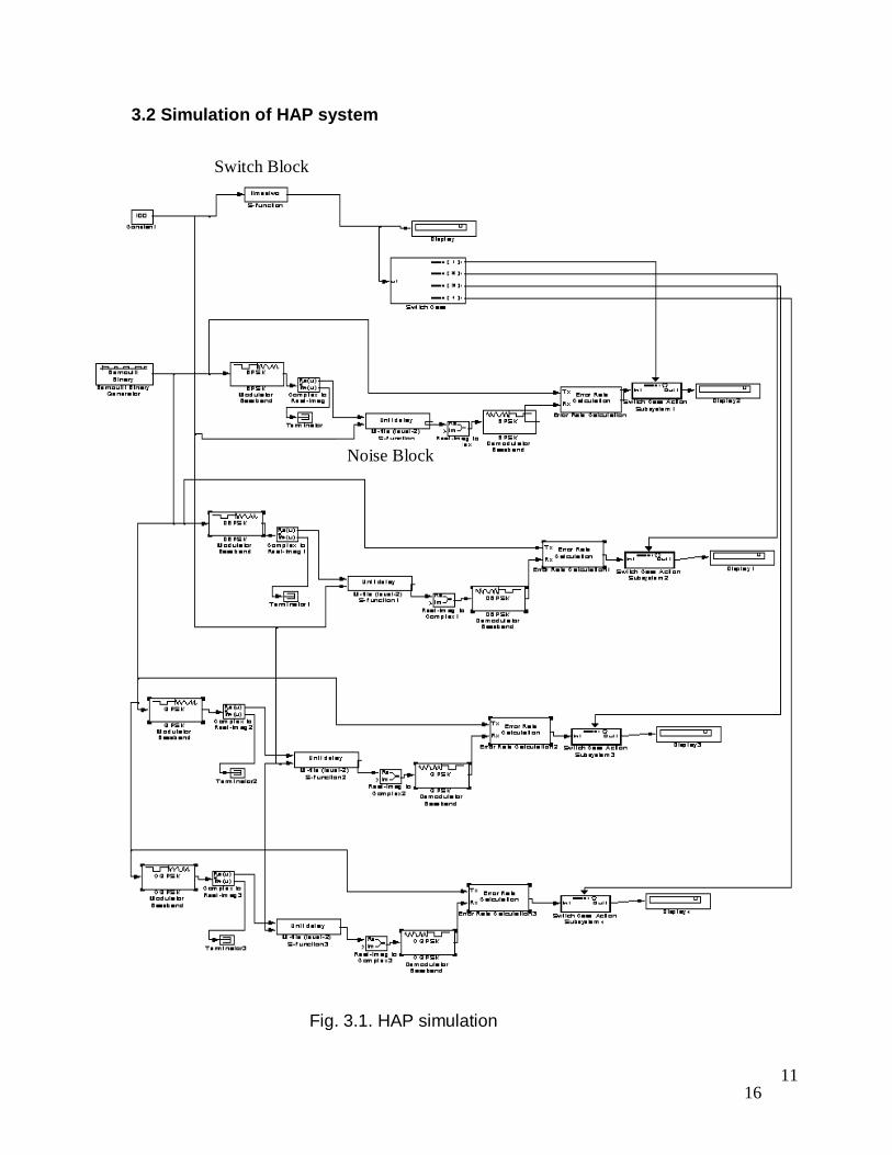
3.2 Simulation of HAP system
Fig. 3.1. HAP simulation
11
Switch Block
Noise Block

17
Coding for the block that switches the modulation technique (Level-1 M file S function) function [sys,x0,str,ts]=noise_sfcn(t, x, u, flag, Cint, Tint) % Déclaration des variable switch flag case 0 % initialize str=[] ; ts = [0 0] ; s = simsizes ; s.NumContStates = 2 ; s.NumDiscStates = 0 ; s.NumOutputs = 2 ; s.NumInputs = 1 ; s.DirFeedthrough = 0 ; s.NumSampleTimes = 1 ; sys = simsizes(s) ; x0 = [Cint, Tint]; case 1 % derivatives N=500; k=10; D=1000; Fe=k*D; te=1/Fe; A=-10; flag=0; for i=1:N*k, Tet(i)=te*i; end sys = 0; F=[0:(N*k)-1]*Fe/(N*k); [M]=noise(Signal,SNR); ; sys = [Cint Tint]; case 3 % output sys = x; case {2 4 9} % 2:discrete % 4:calcTimeHit % 9:termination sys =[];
12

18
otherwise error(['unhandled flag =',num2str(flag)]) ; end function [sys,x0,str,ts] = mdlInitializeSizes % Call function simsizes to create the sizes structure. sizes = simsizes; % Load the sizes structure with the initialization information. sizes.NumContStates= 0; sizes.NumDiscStates= 0; sizes.NumOutputs= 1; sizes.NumInputs= 1; sizes.DirFeedthrough=1; sizes.NumSampleTimes=1; % Load the sys vector with the sizes information. sys = simsizes(sizes); % x0 = []; % No continuous states % str = []; % No state ordering % ts = [-1 0]; % Inherited sample time % End of mdlInitializeSizes. function [y]=noise(signal,SNR) output= awgn(signal,SNR) if (SNR>=0 && SNR<=10) y=1 elseif (SNR>10 && SNR<=20) y=2 elseif (SNR>20 && SNR<=30) y=3 else y=4 end
13

19
Coding for modulation block that with an external SNR parameter (Level-2 M file S function) setup(block); function setup(block) block.NumDialogPrms = 1; %% Register number of input and output ports block.NumInputPorts = 2; block.NumOutputPorts = 1; %% Setup functional port properties to dynamically %% inherited. block.SetPreCompInpPortInfoToDynamic; block.SetPreCompOutPortInfoToDynamic; block.InputPort(1).Dimensions = 1; block.InputPort(1).DirectFeedthrough = false; block.InputPort(2).Dimensions = 1; block.OutputPort(1).Dimensions = 1; %% Set block sample time to inherited block.SampleTimes = [.1 0]; %% Register methods block.RegBlockMethod('PostPropagationSetup', @DoPostPropSetup); block.RegBlockMethod('InitializeConditions', @InitConditions); block.RegBlockMethod('Outputs', @Output); block.RegBlockMethod('Update', @Update); %endfunction function DoPostPropSetup(block) %% Setup Dwork block.NumDworks = 1; block.Dwork(1).Name = 'x0'; block.Dwork(1).Dimensions = 1; block.Dwork(1).DatatypeID = 0; block.Dwork(1).Complexity = 'real'; block.Dwork(1).UsedAsDiscState = true;
14

20
%endfunction function InitConditions(block) %% Initialize Dwork block.Dwork(1).Data = block.DialogPrm(1).Data; %endfunction function Output(block) block.OutputPort(1).Data = block.Dwork(1).Data; %endfunction function Update(block) block.Dwork(1).Data = awgn(block.InputPort(1).Data, block.InputPort(2).Data); %endfunction
15

21
3.3 Simulation results
SNR BPSK DBPSK QPSK OQPSK 10 0 0 0 0.5076 5 0 0.01093 0.07104 0.5464 2 0.0512 0.0977 0.1839 0.5747 1 0.077 0.1429 0.244 0.5952 0.75 0.773 0.1548 0.25 0.5925 0.4 0.7738 0.1607 0.256 0.5952 0.3 0.08284 0.1657 0.2781 0.5971 0.2 0.08876 0.1598 0.2781 0.5971 0.1 0.09249 0.1618 0.2832 0.588
Fig. 3.2. BER for different values of SNR(table)
Fig. 3.3. BER for different values of SNR(graph)
OQPSK
BPSK
QPSK
DBPSK
BPSK
SNR (db)
Error
16

22
3.4 Simulation Discussion
In the simulation, an awgn channel block is used as the fading channel. Four different modulation techniques were tested. As seen from Fig. 3.2 it is seen the less the SNR the bit error rate is more. Comparing the for modulation techniques used (BPSK, DBPSK, QPSK and OQPSK) is seen that OQPSK modulation technique the error rate is to high for satisfactory communication. During high levels of attenuation the error rate increases in all 4 cases. From the BER graph in Fig 3.3 it is seen that the BER (bit error rate) for QPSK is higher than DBPSK, which is higher than BPSK for all attenuation levels especially the higher levels. So BPSK should be the ideal choice. However the data rate for QPSK is higher than DBPSK, which is higher than BPSK. So for normal conditions where there is less attenuation and high SNR, QPSK can be used because as seen from the graph the BER is acceptable for QPSK modulation in high SNR conditions.
In the simulation in Figure 3.1 the SNR is read by the switch block that decides the modulation technique is suitable for transmission taking the attenuation level in consideration. Maintaining the integrity is the number one concern in this simulation during low SNR (rainfall condition) values the modulation technique is changed to keep the error rate low sacrificing the speed. However when the SNR is high (clear sky condition) block changes the modulation back to modulation technique where the data transmission rate high and the BER is higher but still acceptable. Since high speed communication is an integral part of HAP it is necessary to maintain a modulation technique that will ensure high data rate. The modulation technique is only changed when SNR is low and data integrity is in stake, which occurs only in adverse weather conditions such as rainfall.
17

23
CONCLUSION
HAPS, which is a rather developing, low-cost and efficient communication technology has been considered in this thesis work as to how it could be used as substitution to or complement satellite and terrestrial communication. HAP combines the benefits of satellite and terrestrial systems. There are still obstacles in it’s development such as the one dealt in this thesis i.e. attenuation caused by rainfall. The simulation results show us that altering modulation techniques with the surrounding attenuation can solve this problem. HAP is still on the drawing board and the problems that are arising are being solved one by one. It can be safely assumed that HAP will be the future of telecommunication industry.
18

24
REFERENCES
[1] Theodore S. Rappaport, “Wireless Communications: Principles and Practice”, Prentice Hall, Second Edition, 1996. [2] William H. Tranter, K. Sam Shanmugan, Theodore S. Rappaport, Kurt L. Kosbar, “Principles of Communication Systems Simulation with Wireless Applications”, Prentice Hall, 2004. [3] Simon Haykin, “Digital Communications”, John Wiley & Sons, 1988. [4] Matthias Pätzold, “Mobile Fading Channels”, John Wiley & Sons, 2002. [5] Andrea Goldsmith, “Wireless Communications”, Cambridge University Press, 2005. [6] Iskandar, Shigeru Shimamoto, “The Channel Characterization and Performance Evaluation of Mobile Communication Employing Stratospheric Platforms”, IEEE Comm. Mag., July 2005. [7] T.C. Tozer, D. Grace, “High-altitude Platforms for Wireless Communications” IEEE Comm. Mag., June 2001. [8] S. Karapantazis and F.-N. Pavlidou, “Broadband communications via HAPS – A survey ” [9] Fernando Ulloa-Vasquez, J.A. Delgado-Penin, “Performance Simulation of High Altitude Platforms (HAPs) Communication Systems”, Report on EC-sponsored IST Project Helinet. [10] Jose Luis Cuevas-Ruiz, Jose A. Delgado, “A Statistical Switched Broadband Channel Model for HAPs Links”, IEEE Comm. Mag., March 2004. [11] Fabio Dovis, Roberto Fantini, et al, “Small-scale Fading for High-altitude Platform (HAP) Propagation Channels”, IEEE Comm. Mag., VOL. 20, NO. 3, April 2002. [12] Goran M. Djuknic, John Freidenfelds, Yuriy Okunev, “Establishing Wireless Communications Services via High-Altitude Aeronautical Platforms: A Concept Whose Time Has Come?”, IEEE Comm. Mag., September 1997 [13] http://www.wikipedia.org
19