jsf data file description - awi
TRANSCRIPT

EdgeTech
4 Little Brook Road
West Wareham, MA 02576
Tel: (508) 291-0057
Fax: (508) 291-2491
www.EdgeTech.com
JSF DATA FILE DESCRIPTION
0004824_REV_1.20 March 2016

ii
JSF DATA FILE DESCRIPTION 0004824_REV_1.20
The information, figures, and specifications in this manual are proprietary and are issued in strict confidence on condition that they not be copied, reprinted, or disclosed to a third party, either wholly or in part, without the prior, written consent of EdgeTech. Any reproduction of EdgeTech supplied software or file sharing is strictly prohibited.
©Copyright 2016 by EdgeTech. All rights reserved.

iii
CUSTOMER SERVICE
Customer service personnel at EdgeTech are always eager to hear from users of our products. Your
feedback is welcome, and is a valuable source of information which we use to continually improve these
products. We encourage you to contact EdgeTech Customer Service to offer any suggestions or to
request technical support:
E-mail: [email protected]
Mail: 4 Little Brook Road West Wareham, MA 02576
Telephone: (508) 291-0057
Facsimile: (508) 291-2491
24-Hour Emergency Technical Support Line: (508) 942-8043
For more information please go to www.EdgeTech.com.

iv
JSF DATA FILE DESCRIPTION 0004824_REV_1.20
ABOUT THIS DOCUMENT
Purpose of this Document
The purpose of this document is to describe the messages of common interest to those reading and
processing JSF files. Although this document discusses the latest messages, some components may be
periodically upgraded or updated. Therefore, the information in this document is subject to change and
should be used for reference only.
License Statement
The JSF Data File Description is not covered by any license. It is being provided to you to facilitate
reading and processing the JSF files produced by EdgeTech’s sonar products and systems. This
document is the property of EdgeTech and is being provided with limited rights to its use.
Limitation of Liability
In no event will EdgeTech be liable for any damages, claims, or costs whatsoever arising from this
agreement and/or your use of this document, or any component thereof, including and without
limitation: any consequential, indirect, incidental damages; or any lost profits or lost savings, even if a
representative has been advised of the possibility of such loss, damages, claims, or costs; or for any
claim by any third party. EdgeTech reserves the right to update the documentation without notice at any
time.
Distribution
EdgeTech does not grant the right to give away, sell, license, re-package, or otherwise distribute any
portion of this document without the written permission of EdgeTech, Inc.
Revision History
REV DESCRIPTION DATE APPROVAL
1.20 Updated to include latest messages and reformatted for easier reading
03/15/2016 HS

v
WARRANTY DISCLAIMER
EdgeTech provides this document to you without any express or implied warranties of any kind,
including, but not limited to: any implied warranties of merchantability or fitness for a particular
purpose. EdgeTech makes no representations or warranties of any kind with respect to any support
services it may render to you.
EdgeTech does not warrant that the document will meet your requirements, or that the document
contains no defects or errors. You assume full responsibility for the selection, possession, performance,
and proper installation and use of this document for verifying the results obtained therefrom.
EdgeTech is under no obligation to provide any support under this license agreement, including
upgrades or future versions of the document, or any portions thereof, to developer, end user, or to any
other party.

vi
JSF DATA FILE DESCRIPTION 0004824_REV_1.20
TABLE OF CONTENTS
CUSTOMER SERVICE ..................................................................................................................................... iii
ABOUT THIS DOCUMENT ............................................................................................................................. iv
Purpose of this Document ....................................................................................................................... iv
License Statement .................................................................................................................................... iv
Limitation of Liability ............................................................................................................................... iv
Distribution .............................................................................................................................................. iv
Revision History ....................................................................................................................................... iv
Warranty Disclaimer ..................................................................................................................................... v
TABLE OF CONTENTS .................................................................................................................................... vi
LIST OF FIGURES ......................................................................................................................................... viii
LIST OF TABLES ............................................................................................................................................. ix
1.0 OVERVIEW ............................................................................................................................................ 1-1
1.1 A Typical JSF File............................................................................................................................ 1-1
1.2 Byte Ordering ................................................................................................................................ 1-2
1.3 Reading a JSF File .......................................................................................................................... 1-2
2.0 FILE FORMAT DEFINITION .................................................................................................................... 2-1
2.1 Message Header ........................................................................................................................... 2-1
2.2 Acoustic Messages ........................................................................................................................ 2-3
2.2.1 Message Type 80: Sonar Data Message ................................................................................. 2-3
2.2.2 Message Type 82: Side Scan Data Message (Legacy) ........................................................... 2-13
2.3 Other Messages .......................................................................................................................... 2-16
2.3.1 Message Type 182: System Information .............................................................................. 2-16
2.3.2 Message Type 426: File Timestamp Message ...................................................................... 2-16
2.3.3 Message Type 428: File Padding Message ........................................................................... 2-17
2.4 Auxiliary Messages ...................................................................................................................... 2-17
2.4.1 Message Type 2002: NMEA String ....................................................................................... 2-17
2.4.2 Message Type 2020: Pitch Roll Data .................................................................................... 2-17
2.4.3 Message Type 2060: Pressure Sensor Reading .................................................................... 2-19
2.4.4 Message Type 2080: Doppler Velocity Log Data (DVL) ........................................................ 2-20
2.4.5 Message Type 2090: Situation Message .............................................................................. 2-21

vii
2.4.6 Message Type 2091: Situation Comprehensive Message (Version 2) ................................. 2-23
2.4.7 Message Type 2100: Cable Counter Data Message ............................................................. 2-25
2.4.8 Message Type 2101: Kilometer of Pipe Data ....................................................................... 2-25
2.5 Message Type 2111: Container Timestamp Message ................................................................ 2-26

viii
JSF DATA FILE DESCRIPTION 0004824_REV_1.20
LIST OF FIGURES
Figure 1-1: Utility Showing Typical Messages Contained within a JSF File ................................................ 1-1
Figure 1-2: Example C Code for Reading a JSF File .................................................................................... 1-2

ix
LIST OF TABLES
Table 2-1: Message Type 80 Data Format Block ........................................................................................ 2-6
Table 2-2: Message Type 80 Navigation Data Block .................................................................................. 2-6
Table 2-3: Message Type 80 Pulse Information Block ............................................................................... 2-8
Table 2-4: Message Type 80 CPU Time Block ............................................................................................ 2-9
Table 2-5: Message Type 80 Weighting Factor Block ................................................................................ 2-9
Table 2-6: Message Type 80 Orientation Sensor Data Block ................................................................... 2-10
Table 2-7: Message Type 80 Trigger Information Block .......................................................................... 2-10
Table 2-8: Message Type 80 NMEA Navigation Data Block ..................................................................... 2-11
Table 2-9: Message Type 80 Miscellaneous Data Block .......................................................................... 2-12
Table 2-10: Message Type 82 Data Block ................................................................................................ 2-14
Table 2-11: Message Type 82 Computer Date / Time Data Block ........................................................... 2-15
Table 2-12: Message Type 82 Auxiliary Sensor Information Block .......................................................... 2-15
Table 2-13: Message Type 182 System Information ................................................................................ 2-16
Table 2-14: Message Type 426 File Timestamp ....................................................................................... 2-16
Table 2-15: Message Type 2002 NMEA String ......................................................................................... 2-17
Table 2-16: Message Type 2020 Pitch Roll .............................................................................................. 2-19
Table 2-17: Message Type 2060 Pressure Sensor .................................................................................... 2-19
Table 2-18: Message Type 2080 DVL ....................................................................................................... 2-21
Table 2-19: Message Type 2090 Situation ............................................................................................... 2-23
Table 2-20: Message Type 2091 Situation Comprehensive ..................................................................... 2-24
Table 2-21: Message Type 2100 Cable Counter ...................................................................................... 2-25
Table 2-22: Message Type 2101 Kilometer of Pipe ................................................................................. 2-25
Table 2-23: Message Type 2111 Container .............................................................................................. 2-26


1-1
1.0 OVERVIEW
EdgeTech’s native file format is stored to a binary file with the extension *.JSF. The JSF file has been in
use for over 10 years and is recorded by default by most EdgeTech topsides running the Discover and
JStar acquisition programs.
This document describes the most common messages found in EdgeTech’s JSF files and is not intended
to be a complete description of all messages contained within. This document should also be used in
conjunction with the JSFdefs.h header file to properly read, store, and process JSF files.
1.1 A Typical JSF File
Sonar data is recorded on a per-channel basis: a single frequency side scan system has two messages per
ping–one for port (channel 0) and one for starboard (channel 1). Other types of data, such as those
coming from a motion reference unit (MRU) providing pitch, roll, and heave, have their own specific
message and similarly have a single message per reading set. Different types of data will have different
message numbers as identified by the Message Type field. A typical file might contain the following
messages as depicted in EdgeTech’s JSF File Viewer Utility (FIGURE 1-1).
Figure 1-1: Utility Showing Typical Messages Contained within a JSF File

1-2 OVERVIEW
JSF DATA FILE DESCRIPTION 0004824_REV_1.20
1.2 Byte Ordering
The byte ordering of 16-bit and 32-bit value is important since the JSF format is stored using little endian
(Intel) format for binary data, where the least significant bytes are stored first. This is the native format
for Intel x86 computers and compatibles. If data is read on a big endian machine (such as most Sun
Workstations), the user should byte reverse the data so that the 2 bytes of a 16-bit value are flipped,
and the 4 bytes of a 32-bit value are flipped (i.e., bytes 0, 1, 2, 3 become bytes 3, 2, 1, 0).
1.3 Reading a JSF File
Reading a JSF file does not take much coding. Sample C code for reading an entire JSF file is given below.
All or any part thereof is free to use.
Figure 1-2: Example C Code for Reading a JSF File

2-1
2.0 FILE FORMAT DEFINITION
The JSF file is made up of several types of messages, each beginning with a 16-byte header indicating the
type of data to follow and its size. This section describes the message header along with some of the
potential messages contained within a single JSF file.
2.1 Message Header
The header identifies the type and size of the message, as well as the originating subsystem and
channel. The header format is given in Table 2-1.
BYTE OFFSETS DESCRIPTION SIZE
0 – 1 Marker for the Sync/Start of Header (always 0x1601)
This serves as a sanity check during file processing.
UINT16
2 Protocol Version (e.g.0xD).
The protocol level indicates which revision of this specification was used to write that message. Messages of differing protocol levels may be interspersed in the same file. Protocol level changes may involve additional messages or changes to the non-public portion of the interface.
UINT8
3 Session Identifier
The session identifier is used for internal routing and can be ignored.
UINT8
4 – 5 Message Type (e.g. 80 = Acoustic Return Data)
This field defines the type of data to follow. Some data formats of interest are detailed in the following sections. If this field contains an unwanted or unknown (i.e. not defined) type, use the Size of the Message (bytes 12– 15) to skip over the data to the next message header. The message protocol is used for command and control as well as data.
UINT16
6 Command Type
2 = Normal data source
The command type field can normally be ignored when reading JSF files as this parameter may only be of interest during real time operation.
UINT8

2-2 FILE FORMAT DEFINITION
JSF DATA FILE DESCRIPTION 0004824_REV_1.20
BYTE OFFSETS DESCRIPTION SIZE
7 Subsystem Number
The subsystem number determines the source of data; common subsystem assignments are:
Sub-Bottom (SB) = 0
Low frequency data of a dual frequency side scan = 20
High frequency data of a dual frequency side scan = 21
Very High frequency data of a tri-frequency side scan = 22
Raw Serial/UDP/TCP data =100
Parsed Serial/UDP/TCP data =101
Standard side scan systems are single or dual frequency. When more than two side scan frequencies are present, the subsystem number begins at 20 and increases with increasing acoustic center frequencies.
UINT8
8 Channel for a Multi-Channel Subsystem
For Side Scan Subsystems:
0 = Port
1 = Starboard
For Serial Ports: this will be the logical port number, which often differs from the physical COM port in use.
Single channel Sub-Bottom systems channel is 0.
UINT8
9 Sequence Number UINT8
10 – 11 Reserved UINT16
12 – 15 Size of following Message in Bytes
The byte count is the number of bytes until the start of the next message header. This is the amount of additional data to read if processing the current message, or the amount of data to skip over if the current message is not of interest.
UINT32
Table 2-1: 16-byte Message Header Template

2-3
2.2 Acoustic Messages
There are two possible types of acoustic messages contained within a JSF file. These two types are
described in the subsections that follow.
2.2.1 Message Type 80: Sonar Data Message
The Sonar Data Message is preferred over the Side Scan Data Message (Type 82) and consists of a single
channel ping of data (receiver sounding period) for a single channel (e.g. port side of low frequency side
scan subsystem). Refer to the header file jsfdefs.h for more information.
Most side scan subsystems have two channels of data: port and starboard. Most sub-bottom
subsystems have a single channel of data. Which fields have data present depends on the system used
and data acquisition procedures. In addition, this message may contain data from multiple non-acoustic
sensors. Non-acoustic data contained in this message is not normally time interpolated.
EdgeTech strongly recommends that if high positional or situational accuracy is required, the individual
sensor messages should be processed instead (see sub-section2.4 AUXILIARY MESSAGES). Otherwise, this
may be the only message that needs to be interpreted in a JSF file if the level of accuracy is sufficient.
The Validity Flag field (byte 30-31) indicates which auxiliary fields are populated. By convention, if a
value is not present, the field is set to 0.
A Sonar Data Message consists of a 240 byte header followed by the actual acoustic sample data. This
240-byte header is described in the table below.
BYTE OFFSETS DESCRIPTION SIZE
0 – 3 TimeSince1970
Ping Time in seconds since the start of time-based time function (midnight 1/1/1970)
The time of the start of the ping of data represented by the following trace data is the Ping Time.
This time stamp is only valid for data recorded in Protocol Revision 8 and above, this field is zero in prior protocol versions.
INT32
4 – 7 Starting Depth (window offset) in Samples UINT32
8 – 11 Ping Number (increases with each ping) UINT32
12 – 15 Reserved 2 x INT16
2-4 FILE FORMAT DEFINITION
JSF DATA FILE DESCRIPTION 0004824_REV_1.20
BYTE OFFSETS DESCRIPTION SIZE
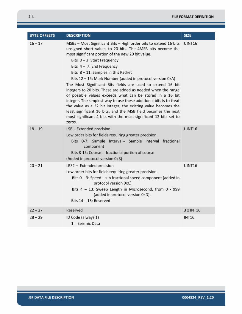
16 – 17 MSBs – Most Significant Bits – High order bits to extend 16 bits unsigned short values to 20 bits. The 4MSB bits become the most significant portion of the new 20 bit value.
Bits 0 – 3: Start Frequency
Bits 4 – 7: End Frequency
Bits 8 – 11: Samples in this Packet
Bits 12 – 15: Mark Number (added in protocol version 0xA)
The Most Significant Bits fields are used to extend 16 bit integers to 20 bits. These are added as needed when the range of possible values exceeds what can be stored in a 16 bit integer. The simplest way to use these additional bits is to treat the value as a 32 bit integer, the existing value becomes the least significant 16 bits, and the MSB field becomes the next most significant 4 bits with the most significant 12 bits set to zeros.
UINT16
18 – 19 LSB – Extended precision
Low order bits for fields requiring greater precision.
Bits 0-7: Sample Interval-- Sample interval fractional component
Bits 8-15: Course- - fractional portion of course
(Added in protocol version 0xB)
UINT16
20 – 21 LBS2 – Extended precision
Low order bits for fields requiring greater precision.
Bits 0 – 3: Speed - sub fractional speed component (added in protocol version 0xC).
Bits 4 – 13: Sweep Length in Microsecond, from 0 - 999 (added in protocol version 0xD).
Bits 14 – 15: Reserved
UINT16
22 – 27 Reserved 3 x INT16
28 – 29 ID Code (always 1)
1 = Seismic Data
INT16

2-5
BYTE OFFSETS DESCRIPTION SIZE
30 – 31 Validity Flag
Validity flags bitmap:
Bit 0: Lat Lon or XY valid
Bit 1: Course valid
Bit 2: Speed valid
Bit 3: Heading valid
Bit 4: Pressure valid
Bit 5: Pitch roll valid
Bit 6: Altitude valid
Bit 7: Reserved
Bit 8: Water temperature valid
Bit 9 : Depth valid
Bit 10: Annotation valid
Bit 11: Cable counter valid
Bit 12: KP valid
Bit 13: Position interpolated
Bit 14: Water sound speed valid
UINT16
32 – 33 Reserved UINT16
34 – 35 Data Format
0 = one short per sample - envelope data. The total number of bytes of data to follow is 2 * samples.
1 = two shorts per sample - stored as real (one short), imaginary (one short). The total number of bytes of data to follow is 4 * samples.
2 = one short per sample - before matched filter. The total number of bytes of data to follow is 2 * samples.
9 = two shorts per sample - stored as real (one short), imaginary (one short), - prior to matched filtering. This is the code for unmatched filtered analytic data, whereas value 1 is intended for match filtered analytic data. The total number of bytes of data to follow is 4 * samples.
NOTE: Values greater than 255 indicate that the data to follow is compressed and must be decompressed prior to use. For more detail refer to the JSF Data File Decompression Application Note for more information.
INT16
36 – 37 Distance from Antenna to Tow point in Centimeters
Sonar Aft is Positive
INT16

2-6 FILE FORMAT DEFINITION
JSF DATA FILE DESCRIPTION 0004824_REV_1.20
BYTE OFFSETS DESCRIPTION SIZE
38 – 39 Distance from Antenna to Tow Point in Centimeters
Sonar to Starboard is Positive.
INT16
40 – 43 Reserved 2 x INT16
Table 2-1: Message Type 80 Data Format Block
BYTE OFFSETS DESCRIPTION SIZE
44 – 47 Kilometers of Pipe
See Validity Flag (bytes 30 – 31).
FLOAT32
48 – 79 Reserved 16 x INT16
80 – 83 Longitude in 10000 * (Minutes of Arc) or X in Millimeters or in Decimeters. See Validity Flag (bytes 30 – 31) and Coordinate Units (bytes 88 - 89).
NOTE: Unless the Validity Flag Bit 13 “Position Interpolated” is set, the position stored in message 80 is the value recorded by Discover and is not the sonar’s position. It is the last navigation position received prior to pinging and Layback is not applied.
INT32
84 – 87 Latitude in 10000 * (Minutes of Arc) or Y in Millimeters or in Decimeters. See Validity Flag (bytes 30 – 31) and Coordinate Units (bytes 88 - 89).
NOTE: Unless the Validity Flag Bit 13 “Position Interpolated” is set, the position stored in message 80 is the value recorded by Discover and is not the sonar’s position. It is the last navigation position received prior to pinging and Layback is not applied.
INT32
88 – 89 Coordinate Units
1 = X, Y in millimeters
2 = Latitude, longitude in minutes of arc times 10000
3 = X, Y in decimeters
INT16
Table 2-2: Message Type 80 Navigation Data Block

2-7
BYTE OFFSETS DESCRIPTION SIZE
90 – 113 Annotation String (ASCII Data) 24 x UINT8
114 – 115 Samples
NOTE: For protocol versions 0xA and above, the MSB1 field should include the MSBs (Most Significant Bits) needed to determine the number of samples.
See bits 8-11 in bytes 16-17. Field MSB1 for MSBs for large sample sizes.
UINT16
116 – 119 Sampling Interval in Nanoseconds
NOTE: For protocol versions 0xB and above, see the LSBs field should include the fractional component needed to determine the sample interval.
See bits 0-7 in bytes 18-19. Field LSB1 for LSBs for increased precision.
UINT32
120 – 121 Gain Factor of ADC UINT16
122 – 123 User Transmit Level Setting (0 – 100%). INT16
124 – 125 Reserved INT16
126 – 127 Transmit Pulse Starting Frequency in daHz (decaHertz, units of 10Hz).
NOTE: For protocol versions 0xA and above, the MSB1 field should include the MSBs (Most Significant Bits) needed to determine the starting frequency of transmit pulse.
See Bits 0-3 in byte 16-17. Field MSB1 for MSBs for large transmit pulse.
UINT16
128 – 129 Transmit Pulse Ending Frequency in daHz (decaHertz, units of 10Hz).
NOTE: For protocol versions 0xA and above, the MSB1 field should include the MSBs (Most Significant Bits) needed to determine the starting frequency of transmit pulse.
See bits 4-7 in byte 16-17. Field MSB1 for MSBs for large transmit pulse.
UINT16
130 – 131 Sweep Length in Milliseconds.
See bytes 18-19 for LSBs (Least Significant Bits), LSB2 bits 4 - 13 contain the microsecond portion (0 - 999). LSB2 part was added in protocol version 0xD, and was previously 0.
UINT16
132 – 135 Pressure in Milli PSI (1 unit = 1/1000 PSI)
See Validity Flag (bytes 30-31)
INT32
136 – 139 Depth in Millimeters (if not = 0)
See Validity Flag (bytes 30-31).
INT32

2-8 FILE FORMAT DEFINITION
JSF DATA FILE DESCRIPTION 0004824_REV_1.20
BYTE OFFSETS DESCRIPTION SIZE
140 – 141 Sample Frequency of the Data in hertz
NOTE: For all data types EXCEPT RAW (Data Format = 2) this is the sampling frequency of the data. For RAW data, this is one-half the sample frequency of the data (FS/2). All values are modulo 65536. Use this in conjunction with the Sample Interval (bytes 114-115) to calculate correct sample rate.
UINT16
142 – 143 Outgoing Pulse Identifier UINT16
144 – 147 Altitude in Millimeters
A zero implies not filled. See Validity Flag (bytes 30-31)
INT32
148 – 151 Sound Speed in Meters per Second.
See Validity Flag (bytes 30-31).
FLOAT
152 – 155 Mixer Frequency in Hertz
For single pulses systems this should be close to the center frequency.
For multi pulse systems this should be the approximate center frequency of the span of all the pulses.
FLOAT
Table 2-3: Message Type 80 Pulse Information Block

2-9
BYTE OFFSETS DESCRIPTION SIZE
156 – 157 Year Data Recorded (CPU time) e.g. 2009.
The Ping Time can also be determined from the Year, Day, Hour, Minute and Seconds as per bytes 156 to 165. Provides 1 second level accuracy and resolution.
See Bytes 0-3 these 2 time stamps are equivalent and identical. For most purposes this should not be used.
For higher resolution (milliseconds) use the Year, and Day values of bytes 156 to 159, and then use the milliSecondsToday value of bytes 200-203 to complete the timestamp.
System time is set to UTC, regardless of time zone. This time format is backwards compatible with all older Protocol Revisions
INT16
158 – 159 Day (1 – 366) (should not be used) INT16
160 – 161 Hour (see Bytes 200-203) (should not be used) INT16
162 – 163 Minute (should not be used) INT16
164 – 165 Second (should not be used) INT16
166 – 167 Time Basis (always 3) INT16
Table 2-4: Message Type 80 CPU Time Block
The trace data is transmitted as 16 bit integers in block floating point format per message. This saves
bandwidth and storage space while preserving dynamic range. The weighting factor MUST be applied to
each of the 16 bit integer values to restore the original floating point value.
BYTE OFFSETS DESCRIPTION SIZE
168 – 169 Weighting Factor for Block Floating Point Expansion -- defined as 2 to N Volts for LSB.
All data MUST be scaled by 2-N, where N is the Weighting Factor.
(See Equation 2-1, on page 2-8)
INT16
170 – 171 Number of Pulses in the Water INT16
Table 2-5: Message Type 80 Weighting Factor Block

2-10 FILE FORMAT DEFINITION
JSF DATA FILE DESCRIPTION 0004824_REV_1.20
Each of the data samples then needs to be scaled by the weighting factor, N, according to the equation
below:
𝑆𝑐𝑎𝑙𝑒𝑑𝐷𝑎𝑡𝑎𝑆𝑎𝑚𝑝𝑙𝑒 = 𝐷𝑎𝑡𝑎𝑆𝑎𝑚𝑝𝑙𝑒 × 2−𝑁
Equation 2-1
The following Compass Heading, Pitch and Roll fields contain useful information about the attitude of
the sonar.
BYTE OFFSETS DESCRIPTION SIZE
172 – 173 Compass Heading (0 to 359.99) in units of 1/100 Degree.
See Validity Flag (bytes 30-31).
The Compass heading is the magnetic heading of the towfish. If a Gyro sensor is properly interfaced to the DISCOVER Topside Acquisition Unit with a valid NMEA HDT message, this field will contain the Gyro heading, relative to True North.
UINT16
174 – 175 Pitch [(degrees / 180.0) * 32768.0] maximum resolution.
Positive values indicate bow up.
See Validity Flag (bytes 30-31).
INT16
176 – 177 Roll [(degrees / 180.0) * 32768.0] maximum resolution.
Positive values indicate port up.
See Validity Flag (bytes 30-31).
INT16
178 – 179 Reserved INT16
Table 2-6: Message Type 80 Orientation Sensor Data Block
Also, the trigger source is determined from this block.
BYTE OFFSETS DESCRIPTION SIZE
180 – 181 Reserved INT16
182 – 183 Trigger Source
0 = Internal
1 = External
2 = Coupled
INT16
184 – 185 Mark Number
0 = No Mark
See bytes 16 –17 fields MSB1 for MSBs (Most Significant Bits) for large values (> 655350).
UINT16
Table 2-7: Message Type 80 Trigger Information Block

2-11
The following Position Fix Hour, Position Fix Minutes, and Position Fix Seconds fields (bytes 186-193)
contain the time of the last position fix. If bit 13 is set (i.e. position interpolated) in Validity Flag (bytes
30-31), this will be the same as the CPU and ping time.
BYTE OFFSETS DESCRIPTION SIZE
186 – 187 Position Fix Hour (0 – 23)
NOTE: the NAV time is the time of the latitude and longitude fix.
INT16
188 – 189 Position Fix Minutes (0 – 59)
NOTE: the NAV time is the time of the latitude and longitude fix.
INT16
190 – 191 Position Fix Seconds (0 – 59)
NOTE: the NAV time is the time of the latitude and longitude fix.
INT16
192 – 193 Course in Degrees (0 to 359.9)
Starting with protocol version 0x0C two digits of fractional degrees are stored in LSB1. Fractional portion in LSBs (Least Significant Bits). See bytes 18 – 19.
INT16
194 – 195 Speed – in Tenths of a Knot
Starting with protocol version 0x0C one additional digit of fractional knot (1/100) is stored in LSB2. For an additional fractional digit, see LSB2 (bytes 20 -21).
INT16
196 – 197 Position Fix Day (1 – 366) INT16
198 – 199 Position Fix Year INT16
Table 2-8: Message Type 80 NMEA Navigation Data Block
BYTE OFFSETS DESCRIPTION SIZE
200 – 203 Milliseconds Today (Since Midnight)
Use with seconds since 1970 to get time to the milliseconds (time of Ping).
UINT32
204 – 205 Maximum Absolute Value of ADC Samples in this Packet UINT16
206 – 207 Reserved INT16
208 – 209 Reserved INT16
210 – 215 Sonar Software Version Number - ASCII 6 x INT8
216 – 219 Initial Spherical Correction Factor in Samples times 100.
A value of -1 indicates that the spherical spreading is disabled.
INT32

2-12 FILE FORMAT DEFINITION
JSF DATA FILE DESCRIPTION 0004824_REV_1.20
BYTE OFFSETS DESCRIPTION SIZE
220 – 221 Packet Number
Each ping starts with packet 1
UINT16
222 – 223 ADC Decimation * 100 times INT16
224 – 225 Reserved INT16
226 – 227 Water Temperature in Units of 1/10 Degree C.
See Validity Flag (bytes 30-31).
INT16
228 – 231 Layback
Distance to the sonar in meters.
FLOAT32
232 – 235 Reserved INT32
236 – 237 Cable Out in Decimeters
See Validity Flag bytes 30-31).
UINT16
238 – 239 Reserved UINT16
Table 2-9: Message Type 80 Miscellaneous Data Block
Sonar trace data follows the 240-byte header and consists of 16 bit integer values. The number of
integers to be read can be found by multiplying the number of samples in the trace (bytes 114-115) by
the number of integers per sample for the Data Format used (1 or 2, bytes 34-35). Furthermore,
doubling this yields the byte size of the data section. This should exactly match the preceding Message
Header byte count (bytes 12-15) less the header size of 240.

2-13
2.2.2 Message Type 82: Side Scan Data Message (Legacy)
Side Scan Data Messages (Type 82) are no longer used but are described here for historical purposes
(refer to the header file sidescandefs.h for more information). While configuring Sonar to generate these
messages is still possible, new systems are not configured in this manner. If the user’s sonar system is
storing Side Scan Data Messages (Type 82) the configuration should be changed to store Sonar Data
Messages (Type 80) instead.
Side Scan Data Messages (Type 82) are never stored by EdgeTech’s Discover Acquisition Program, and
are only encountered in data stored by Sonar. Data recorded by Sonar are almost always recorded in a
compressed format, rendering it unusable without further processing. Please refer to the JSF Data File
Decompression Application Note for more information.
A Side Scan Data Message (Type 82) is similar to a Sonar Data Message (Type 80) as it contains the exact
same acoustic data. Originally the Side Scan Data Message (Type 82) was intended for Side Scan data
only but it has been used to store Sub-Bottom data as well. The system configuration determines which
type of data is actually present. Each Side Scan Data Message has an 80 byte header, the content of
which is defined below. As with Sonar Data Messages, unused fields should be set to 0.
BYTE OFFSETS DESCRIPTION SIZE
0 – 1 Subsystem
The subsystem number determines the source of data; common subsystem assignment are:
Sub-Bottom (SB) = 0
Low frequency data of a dual frequency side scan = 20
High frequency data of a dual frequency side scan = 21
Very High frequency data of a tri-frequency side scan = 22
Raw Serial/UDP/TCP data = 100
Parsed Serial/UDP/TCP data = 101
Standard side scan systems are single or dual frequency. When more than two side scan frequencies are present, the subsystem number for side scan frequencies begins at 20 and increases with increasing acoustic center frequencies.
UINT16
2 – 3 Channel for a Multi-Channel Subsystem
For Side Scan Subsystems:
0 = Port
1 = Starboard
For Serial Ports: this is the logical port number, which often differs from physical COM Port in use.
Single Channel Sub-Bottom systems channel is 0.
UINT16

2-14 FILE FORMAT DEFINITION
JSF DATA FILE DESCRIPTION 0004824_REV_1.20
BYTE OFFSETS DESCRIPTION SIZE
4 – 7 Ping Number (increments with each ping period) UINT32
8 – 9 Packet Number (1..n, each ping starts with packet 1) UINT16
10 – 11 Trigger Source (0 = internal, 1 = external) UINT16
12 – 15 Samples in this Packet UINT32
16 – 19 Sample Interval in Nanoseconds of Stored Data UINT32
20 – 23 Starting Depth (window offset) in Samples UINT32
24 – 25 Weighting Factor (defines 2 to N Volts)
See Equation 3-1, page 2-8.
INT16
26 – 27 Gain Factor of ADC UINT16
28 – 29 Maximum Absolute Value for ADC Samples for this Packet UINT16
30 – 31 Range Setting (in decameters, meters times 10) UINT16
32 – 33 Unique Pulse Identifier UINT16
34 – 35 Mark Number (0 = no mark) UINT16
36 – 37 Data Format
0 = one short per sample - envelope data the total number of bytes of data to follow is 2 * samples
1 = two shorts per sample - stored as real (one short), imaginary (one short), the total number of bytes of data to follow is 4 * samples
NOTE: Values greater than 255 indicate that the data to follow is compressed and must be decompressed prior to use. For more detail refer to the JSF Data File Decompression Application Note for more information.
UINT16
38 Number of Simultaneous Pulses in the Water UINT8
39 Reserved UINT8
Table 2-10: Message Type 82 Data Block

2-15
BYTE OFFSETS DESCRIPTION SIZE
40 – 43 Milliseconds Today UINT32
44 – 45 Year INT16
46 – 47 Day of year (1 – 366) UINT16
48 – 49 Hour of day (0 – 23) UINT16
50 – 51 Minute (0 – 59) UINT16
52 – 53 Second (0 – 59) UINT16
Table 2-11: Message Type 82 Computer Date / Time Data Block
BYTE OFFSETS DESCRIPTION SIZE
54 – 55 Compass Heading in Minutes (0 – 359.9) x 60 UINT16
56 – 57 Pitch (scale by 180 / 32768 to get degrees, bow up is positive) INT16
58 – 59 Roll (scale by 180 / 32768 to get degrees, port up is positive) INT16
60 – 61 Heave in Centimeters INT16
62 – 63 Yaw in Minutes INT16
64 – 67 Pressure in Units of 1/1000 PSI UINT32
68 – 69 Temperature in Units of 1/10 of a Degree Celsius INT16
70 – 71 Reserved INT16
72 – 75 Altitude in Millimeters (or -1 if no valid reading) INT32
76 – 79 Reserved 4 x UINT8
Table 2-12: Message Type 82 Auxiliary Sensor Information Block
Sonar trace data follows the 80-byte header and consists of 16 bit integer values. The number of
integers to be read can be found by multiplying the number of samples in the trace (bytes 12-15) by the
number of integers per sample for the Data Format used (1 or 2, bytes 36-37).
Furthermore, doubling this yields the byte size of the data section. This should exactly match the
preceding 16 byte Message Header byte count (bytes 12 –15) less the header size of 80.

2-16 FILE FORMAT DEFINITION
JSF DATA FILE DESCRIPTION 0004824_REV_1.20
2.3 Other Messages
The JSF file also contains messages other than acoustic records. For example, there are system and
timestamp information messages and sometimes a padding message may also be included. These
structures are defined in the following subsections.
2.3.1 Message Type 182: System Information
The system information message contains details of the system used to acquire data. This message is
normally present at the beginning of a JSF file, and may be repeated if configuration parameters change.
BYTE OFFSETS DESCRIPTION SIZE
0 – 3 System Type INT32
4 – 7 Low Rate I/O Enabled Option (0 = disabled) INT32
8 – 11 Version Number of Sonar Software used to Generate Data INT32
12 – 15 Number of Subsystems Present in this Message INT32
16 – 19 Number of Serial Port Devices Present in this Message INT32
20 – 23 Serial Number of Tow Vehicle used to Collect Data INT32
24 – End Reserved
Table 2-13: Message Type 182 System Information
The size of the System Information Message is subject to change, as more detailed information may be
added in future versions of the software. The byte count in the message header should be used to
determine the total size of the structure and jump over to the next message in the file.
2.3.2 Message Type 426: File Timestamp Message
Timestamp messages, if present, are often found at the beginning and end of a file. They contain the
following fields:
BYTE OFFSETS DESCRIPTION SIZE
0 – 3 Time in Seconds since 1/1/1970 INT32
4 – 7 Milliseconds in the Current Second INT32
Table 2-14: Message Type 426 File Timestamp

2-17
2.3.3 Message Type 428: File Padding Message
A file padding message is sometimes found at the end of the file. In some implementations files are
padded to optimize the write process. These messages should be ignored.
2.4 Auxiliary Messages
The JSF file may also contain auxiliary data messages from various sensors depending on the
configuration. These auxiliary messages are but not limited to: NMEA strings, attitude records, pressure
readings, Doppler Velocity Log (DVL) data, cable counter data, and kilometer of pipe information. These
data blocks are described in the subsections below.
2.4.1 Message Type 2002: NMEA String
A NMEA string consists of a time stamp followed by an ASCII string as read from a GPS, Gyro, or other
device. Each message is a single string excluding the <CR>/<LF>.
BYTE OFFSETS DESCRIPTION SIZE
0 – 3 Time in Seconds since 1/1/1970 INT32
4 – 7 Milliseconds in the Current Second INT32
8 Source
1 = Sonar
2 = Discover
3 = ETSI
UINT8
9 – 11 Reserved 3 x UINT8
12 – to Message Length
NMEA String Data Remaining Length x INT8
Table 2-15: Message Type 2002 NMEA String
2.4.2 Message Type 2020: Pitch Roll Data
A pitch roll message consists of a single reading from a pitch roll sensor such as a Seatex MRU, TSS or
OCTANS device. Not all devices provide all data for the defined structure. Use the Validity Flags (bytes
36-39) to determine which fields are populated.
BYTE OFFSETS DESCRIPTION SIZE
0 – 3 Time in Seconds since 1/1/1970 INT32
4 – 7 Milliseconds in the Current Second INT32
8 – 11 Reserved 4 x UINT8

2-18 FILE FORMAT DEFINITION
JSF DATA FILE DESCRIPTION 0004824_REV_1.20
BYTE OFFSETS DESCRIPTION SIZE
12 – 13 Acceleration in X
Multiply by (20 * 1.5) / (32768) to get Gs
INT16
14 – 15 Acceleration in Y
Multiply by (20 * 1.5) / (32768) to get Gs
INT16
16 – 17 Acceleration in Z
Multiply by (20 * 1.5) / (32768) to get Gs
INT16
18 – 19 Rate Gyro in X
Multiply by (500 * 1.5) / (32768) to get Degrees/Sec
INT16
20 – 21 Rate Gyro in Y
Multiply by (500 * 1.5) / (32768) to get Degrees/Sec
INT16
22 – 23 Rate Gyro in Z
Multiply by (500 * 1.5) / (32768) to get Degrees/Sec
INT16
24 – 25 Pitch
Multiply by (180.0 / 32768.0) to get Degrees
Bow up is positive
INT16
26 – 27 Roll: Multiply by (180.0 / 32768.0) to get Degrees.
Port up is positive
INT16
28 – 29 Temperature in Units of 1/10 of a Degree Celsius INT16
30 – 31 Device specific info.
This is device specific info provided for Diagnostic purposes.
UINT16
32 – 33 Estimated Heave in Millimeters.
Positive is Down.
INT16
34 – 35 Heading in units of 0.01 Degrees (0…360) UINT16
36 – 39 Data Validity Flags
Bit 0: Ax
Bit 1: Ay
Bit 2: Az
Bit 3: Rx
Bit 4: Ry
Bit 5: Rz
Bit 6: Pitch
Bit 7: Roll
Bit 8: Heave
Bit 9: Heading
Bit 10: Temperature
Bit 11: Device Info
Bit 12: Yaw
INT32
40 – 41 Yaw in units of 0.01 Degrees (0…360) INT16

2-19
BYTE OFFSETS DESCRIPTION SIZE
42 – 43 Reserved INT16
Table 2-16: Message Type 2020 Pitch Roll
2.4.3 Message Type 2060: Pressure Sensor Reading
This message exists in the data stream if a pressure sensor or sound velocity sensor is installed on the
sonar system. While sensors may be configured in different units, the default is PSI absolute for
pressure, and meters per second for sound velocity. Use the Validity Flags (bytes 24-27) to determine
which fields are populated.
BYTE OFFSETS DESCRIPTION SIZE
0 – 3 Time in Seconds since 1/1/1970 INT32
4 – 7 Milliseconds in the Current Second INT32
8 – 11 Reserved 4 x UINT8
12 – 15 Pressure in Units of 1/1000th of a PSI INT32
16 – 19 Temperature in Units of 1/1000th of Degree Celsius. INT32
20 – 23 Salinity in Parts Per Million INT32
24 – 27 Validity Data Flag:
Bit 0: Pressure
Bit 1: Temperature
Bit 2: Salt PPM
Bit 3: Conductivity
Bit 4: Sound velocity
Bit 5: Depth
INT32
28 – 31 Conductivity in Micro-Siemens per Centimeter INT32
32 – 35 Velocity of Sound in Millimeters per Second INT32
36 – 39 Depth in Meters INT32
40 – 75 Reserved 9 x INT 32
Table 2-17: Message Type 2060 Pressure Sensor

2-20 FILE FORMAT DEFINITION
JSF DATA FILE DESCRIPTION 0004824_REV_1.20
2.4.4 Message Type 2080: Doppler Velocity Log Data (DVL)
This is data from a DVL (if fitted) and often includes velocity and altitude readings. Use the Validity Flags
(bytes 12-15) to determine which fields are populated.
BYTE OFFSETS DESCRIPTION SIZE
0 – 3 Time in Seconds since 1/1/1970 INT32
4 – 7 Milliseconds in the Current Second INT32
8 – 11 Reserved 4 x UINT8
12 – 15 Validity Data Flags :
Bit 0: X, Y Velocity Present
Bit 1: 0 = Earth Coordinates, 1= Ship coordinates
Bit 2: Z (Vertical Velocity) Present
Bit 3: X, Y Water Velocity Present
Bit 4: Z (Vertical Water Velocity) Present
Bit 5: Distance to Bottom Present
Bit 6: Heading Present
Bit 7: Pitch Present
Bit 8: Roll Present
Bit 9: Temperature Present
Bit 10: Depth Present
Bit 11: Salinity Present
Bit 12: Sound Velocity Present
Bit 31: Error Detected
Rest : Reserved, Presently 0
UINT32
16 – 31 Four Integers: distance to bottom in centimeters for up to 4 beams.
A value of 0 indicates an invalid or non-existing reading.
4 x INT32
32-33 X Velocity with Respect to the Bottom in millimeters per second.
A positive value indicates Starboard or East.
INT16
34 – 35 Y Velocity with Respect to the Bottom in millimeters per second.
A positive value indicates Forward or North.
INT16
36 – 37 Z Vertical Velocity with Respect to the Bottom in millimeters per second.
A positive value indicates Upward.
INT16
38 – 39 X Velocity with respect to a water layer in millimeters per second.
A positive value indicates Starboard or East.
INT16
40 – 41 Y Velocity with respect to a water layer in millimeters per second.
A positive value indicates Forward or North.
INT16

2-21
BYTE OFFSETS DESCRIPTION SIZE
42 – 43 Z Vertical Velocity with respect to a water layer in millimeters per second.
A positive value indicates Upward.
INT16
44 – 45 Depth from Depth Sensor in Decimeters UINT16
46 – 47 Pitch in units of 0.01 of a Degree (-180 to +180).
A positive value is Bow Up.
INT16
48 – 49 Roll in units of 0.01 of a Degree (-180 to +180).
A positive value is Port Up.
INT16
50 – 51 Heading in units of 0.01 of a Degree (0 to 360) UINT16
52 – 53 Salinity in 1 Part Per Thousand UINT16
54 – 55 Temperature in units of 1/100 of a degree Celsius INT16
56 – 57 Sound Velocity in Meters per Second INT16
58 – 71 Reserved 7 x INT16
Table 2-18: Message Type 2080 DVL
2.4.5 Message Type 2090: Situation Message
A Situation Message is a composite of data from several sensors and is not commonly used (see 2.4.6 for
more information). Use the Validity Flags (bytes 12-15) to determine which fields are valid. The detailed
data structure is shown below:
BYTE OFFSETS DESCRIPTION SIZE
0 – 3 Time in Seconds since 1/1/1970 INT32
4 – 7 Milliseconds in the Current Second INT32
8 – 11 Reserved 4 x UINT8
12 – 15 Validity Data Flags:
Bit 0: Microsecond Time stamp
Bit 1: Latitude
Bit 2: Longitude
Bit 3: Depth
Bit 4: Heading
Bit 5: Pitch
Bit 6: Roll
Bit 7: X Relative Position
Bit 8: Y Relative Position
Bit 9: Z Relative Position
UINT32

2-22 FILE FORMAT DEFINITION
JSF DATA FILE DESCRIPTION 0004824_REV_1.20
BYTE OFFSETS DESCRIPTION SIZE
Bit 10: X Velocity
Bit 11: Y Velocity
Bit 12: Z Velocity
Bit 13: North Velocity
Bit 14: East Velocity
Bit 15: Down Velocity
Bit 16: X Angular Rate
Bit 17: Y Angular Rate
Bit 18: Z Angular Rate
Bit 19: X Acceleration
Bit 20: Y Acceleration
Bit 21: Z Acceleration
Bit 22: Latitude Standard Deviation
Bit 23: Longitude Standard Deviation
Bit 24: Depth Standard Deviation
Bit 25: Heading Standard Deviation
Bit 26: Pitch Standard Deviation
Bit 27: Roll Standard Deviation
16 – 19 Reserved 4 x UINT8
20 – 27 Microsecond Timestamp
Use since 12:00:00 am GMT, January 1, 1970
UINT64
28 – 35 Double float: Latitude in Degrees, North is Positive FLOAT64
36 – 43 Double float: Longitude in Degrees, East is Positive FLOAT64
44 – 51 Double float: Depth in Meters FLOAT64
52 – 59 Double float: Heading in Degrees FLOAT64
60 – 67 Double float: Pitch in Degrees, Bow up is Positive FLOAT64
68 – 75 Double float: Roll in Degrees, Port up is Positive FLOAT64
76 – 83 Double float: X, Forward, Relative Position in Meters, Surge FLOAT64
84 – 91 Double float: Y, Starboard, Relative Position in meters, Sway FLOAT64
92 – 99 Double float: Z, Downward, Relative Position in Meters, Heave FLOAT64
100 – 107 Double float: X, Forward, Velocity in Meters per Second FLOAT64
108 – 115 Double float: Y, Starboard, Velocity in Meters per Second FLOAT64
116 – 123 Double float: Z, Downward, Velocity in meters per Second FLOAT64
124 – 131 Double float: North Velocity in Meters per Second FLOAT64
132 – 139 Double float: East Velocity in Meters per Second FLOAT64
140 – 147 Double float: Down Velocity in Meters per Second FLOAT64

2-23
BYTE OFFSETS DESCRIPTION SIZE
148 – 155 Double float: X Angular rate in Degrees per Second, Port Up is Positive
FLOAT64
156 – 163 Double float: Y Angular rate in Degrees per Second, Bow Up is Positive
FLOAT64
164 – 171 Double float: Z Angular rate in Degrees per Second, Starboard is Positive
FLOAT64
172 – 179 Double float: XX, Forward, Acceleration in Meters per Second Squared
FLOAT64
180 – 187 Double float: Y, Starboard, Acceleration in Meters per Second Squared
FLOAT64
188 – 195 Double float: Z, Downward, Acceleration in Meters per Second Squared
FLOAT64
196 – 203 Double float: Latitude Standard Deviation in Meters FLOAT64
204 – 211 Double float: Longitude Standard Deviation in Meters FLOAT64
212 – 219 Double float: Depth Standard Deviation in Meters FLOAT64
220 – 227 Double float: Heading Standard Deviation in Degrees FLOAT64
228 – 235 Double float: Pitch Standard Deviation in Degrees FLOAT64
236 – 243 Double float: Roll Standard Deviation in Degrees FLOAT64
244 – 275 Reserved 16 x UINT16
Table 2-19: Message Type 2090 Situation
2.4.6 Message Type 2091: Situation Comprehensive Message (Version 2)
The Situation Comprehensive Message is also a composite of data from several sensors, and is preferred
over the Situation Message (Type 2090). Use the Validity Flags (bytes 12-15) to determine which fields
are populated. The detailed data structure is shown below:
BYTE OFFSETS DESCRIPTION SIZE
0 – 3 Time in Seconds since 1/1/1970 INT32
4 – 7 Milliseconds in the Current Second INT32
8 – 11 Reserved 4 x UINT8
12 – 15 Validity Flag:
Bit 0 : Timestamp Provided by the Source Valid
Bit 1: Longitude Valid
Bit 2: Latitude Valid
Bit 3: Depth Valid
Bit 4: Altitude Valid
UINT32

2-24 FILE FORMAT DEFINITION
JSF DATA FILE DESCRIPTION 0004824_REV_1.20
BYTE OFFSETS DESCRIPTION SIZE
Bit 5: Heave Valid
Bit 6: Velocity 1 & 2 Valid
Bit 7: Velocity down Valid
Bit 8: Pitch Valid
Bit 9 : Roll Valid
Bit 10: Heading Valid
Bit 11: Sound Speed Valid
Bit 12: Water Temperature Valid
Others: Reserved, Presently 0.
16 Velocity12 Directions (Velocity1 and Velocity2 Types):
0 = North and East,
1 = Forward and Starboard,
2 = +45 Degrees Rotated from Forward.
BYTE
17 – 19 Reserved 3 x BYTE
20 – 27 Timestamp (0.01 of a microsecond)
Microsecond since 12:00:00AM GST, January 1, 1970. To get seconds since 1970 divide by 1e7)
UINT64
28 – 35 Latitude in Degree (North is Positive) DOUBLE
36 – 43 Longitude in Degree (East is Positive) DOUBLE
44 – 47 Depth in Meter (Below Water Surface) FLOAT
48 – 51 Altitude in Meter (Above Seafloor) FLOAT
52 – 55 Heave in Meter (Positive is Down) FLOAT
56 – 59 Velocity1 in Meters per Second (North Velocity or Forward) FLOAT
60 – 63 Velocity2 in Meters per Second (East Velocity or Starboard) FLOAT
64 – 67 Velocity Down in Meter per Second (Down Velocity) FLOAT
68 – 71 Pitch in Degrees (Bow up is Positive) FLOAT
72 – 75 Roll in Degrees (Port is Positive) FLOAT
76 – 79 Heading in Degrees (0 to 359.9) FLOAT
80 – 83 Sound Speed in Meters per Second FLOAT
84 – 87 Water Temperature (in Degrees Celsius) FLOAT
88 – 99 Reserved 3 x FLOAT
Table 2-20: Message Type 2091 Situation Comprehensive

2-25
2.4.7 Message Type 2100: Cable Counter Data Message
Cable counter data message is defined by the table below.
BYTE OFFSETS DESCRIPTION SIZE
0 – 3 Time in Seconds since 1/1/1970 INT32
4 – 7 Milliseconds in the Current Second INT32
8 – 11 Reserved 4 x UINT8
12 – 15 Cable Length in Meters FLOAT32
16 – 19 Cable Speed in Meters per Second FLOAT32
20 – 21 Cable Length Valid Flag (0 – Invalid) INT16
22 – 23 Cable Speed Valid Flag (0 – Invalid) INT16
24 – 25 Cable Counter Error (0 – No Error) INT16
26 – 27 Cable Tension Valid Flag (0 – Invalid) INT16
28 – 31 Cable Tension in Kilograms FLOAT32
Table 2-21: Message Type 2100 Cable Counter
2.4.8 Message Type 2101: Kilometer of Pipe Data
Kilometer of Pipe data message is as follows:
BYTE OFFSETS DESCRIPTION SIZE
0 – 3 Time in Seconds since 1/1/1970 INT32
4 – 7 Milliseconds in the Current Second INT32
8 Source
1 = Sonar
2 = DISCOVER
3 = ETSI
BYTE
9 – 11 Reserved 3 x BYTE
12 – 15 Kilometer of Pipe (KP) FLOAT
16 – 17 Flag (Valid KP Value) INT16
18 – 19 Flag (KP Report Error) INT16
Table 2-22: Message Type 2101 Kilometer of Pipe

2-26 FILE FORMAT DEFINITION
JSF DATA FILE DESCRIPTION 0004824_REV_1.20
2.5 Message Type 2111: Container Timestamp Message
Some messages contained within the JSF file may be generated by external entities then passed to the
recording system in a message called a Container Message. These messages are only checked to see if
their length matches that specified in the message header; no other type of validation is performed.
Essentially, this message contains the receipt timestamp of the container message and should always
precede the other desired message (e.g. 2111, then 2060).
BYTE OFFSETS DESCRIPTION SIZE
0 – 3 Time in Seconds since 1/1/1970 INT32
4 – 7 Milliseconds in the Current Second INT32
8 – 11 Reserved 4 x UINT8
Table 2-23: Message Type 2111 Container