journal of solid mechanics vol - jsm.iau-arak.ac.ir
TRANSCRIPT

© 2018 IAU, Arak Branch. All rights reserved.
Journal of Solid Mechanics Vol. 10, No. 3 (2018) pp. 655-671
Elastic Wave Propagation at Imperfect Boundary of Micropolar Elastic Solid and Fluid Saturated Porous Solid Half-Space
V. Kaliraman 1,*
, R.K. Poonia 2
1Department of Mathematics, Chaudhary Devi Lal University, Sirsa, Haryana, India
2Department of Mathematics, Chandigarh University, Gharuan, Mohali, Punjab, India
Received 28 June 2018; accepted 29 August 2018
ABSTRACT
This paper deals with the reflection and transmission of elastic waves from
imperfect interface separating a micropolar elastic solid half-space and a fluid
saturated porous solid half-space. Longitudinal and transverse waves impinge
obliquely at the interface. Amplitude ratios of various reflected and transmitted
waves are obtained and computed numerically for a specific model and results
obtained are depicted graphically with angle of incidence of incident waves. It
is found that these amplitude ratios depend on angle of incidence of the
incident wave, imperfect boundary and material properties of half-spaces.
From the present study, a special case when fluid saturated porous half-space
reduces to empty porous solid is also deduced and discussed graphically.
. © 2018 IAU, Arak Branch. All rights reserved.
Keywords : Porous solid; Micro polar elastic solid; Reflection; Transmission;
Longitudinal wave; Transverse wave; Amplitude ratios; Stiffness.
1 INTRODUCTION
OST of natural and man-made materials, including engineering, geological and biological media, possess a
microstructure. The ordinary classical theory of elasticity fails to describe the microstructure of the material.
To overcome this problem, Eringen and Suhubi [10] considered the microstructure of the material and they showed
that the motion in a granular structure material is characterized not by a displacement vector but also by a rotation
vector. Gautheir [12] found aluminum-epoxy composite to be a micro polar material. Many problems of waves and
vibrations have been discussed in micro polar elastic solid by several researchers. Some of them are Parfitt and
Eringen [23], Tomar and Gogna [26], Tomar and Kumar [27], Singh and Kumar [24], Kumar and Barak [18] etc.
On the other side, Brown [4] and de Boer and Ehlers [7-8] developed an interesting theory for porous medium
having all constituents to be incompressible. Based on this theory, many researchers like de Boer and Liu [5], Liu
[21], de Boer and Didwania [6], Tajuddin and Hussaini [25], Kumar and Hundal [16], Kumari [19], Madan et al.
[22], Kumar et al. [14-15] etc. studied some problems of wave propagation in fluid saturated incompressible porous
media. Elastic waves propagation in fluid saturated porous media has its importance in various fields such as soil
dynamics, hydrology, seismology, earthquake engineering and geophysics. Imperfect interface considered in this
problem means that the stress components are continuous and small displacement field is not. The values of the
interface parameters depend upon the material properties of the medium. Recently, using the imperfect conditions at
______ *Corresponding author. Tel.: +91 94664 04929.
E-mail address: [email protected] (V. Kaliraman).
M

V. Kaliraman and R.K. Poonia 656
© 2018 IAU, Arak Branch
the interface, Kumar and Chawla [17], Kumari [20], Kaliraman [13], Barak and Kaliraman [1-2-3] etc. studied the
various types of wave problems.
Using the theory of de Boer and Ehlers [8] for fluid saturated porous medium and Eringen [11] for micro polar
elastic solid, the reflection and transmission phenomenon of longitudinal and transverse waves at an imperfect
interface between micro polar elastic solid half-space and fluid saturated porous solid half-space is studied. A
special case when fluid saturated porous solid half-space reduces to empty porous solid half-space has been deduced
and discussed. Amplitudes ratios for various reflected and transmitted waves are computed for a particular model
and depicted with help of graphs and discussed accordingly. The model which is considered here is assumed to exist
in the oceanic crust part of the Earth and the propagation of wave through such a model will be of great use in the
fields which are related to Earth sciences.
2 FORMULATION OF THE PROBLEM
Consider a two-dimensional problem by taking the z-axis pointing into the lower half-space and the plane interface
0z separating the fluid saturated porous solid half-space 1 0M z and micropolar elastic solid half-
space 2 0M z . A longitudinal wave or transverse wave propagates through the medium 1M and incident at the
plane 0z and making an angle 0 with normal to the surface. Corresponding to incident longitudinal or
transverse wave, we get two reflected waves in the medium 1M and three transmitted waves in medium 2M . See
Fig. 1.
Fig.1
Geometry of the problem.
3 BASIC EQUATIONS AND CONSTITUTIVE RELATIONS
3.1 For medium M2 (Micro polar elastic solid)
The equation of motion in micro polar elastic medium are given by Eringen [11] as:
2
2 2 2
1 3 2c c
t
(1)
2
2 2 2 2
2 3 3 2
Uc c U c
t
(2)
2
2 2 2 2
4 0 0 2c 2 U
t
(3)
where

657 Elastic Wave Propagation at Imperfect Boundary of Micro polar….
© 2018 IAU, Arak Branch
2
1
2c
; 2
2c
; 2
3c
;
2
4cj
;
2
0j
(4)
Parfitt and Eringen [23] have shown that Eq. (1) corresponds to longitudinal wave propagating with velocity 1v ,
given by 2 2 2
1 1 3v c c and Eqs. (2)-(3) are coupled equations in vector potential U and and these correspond to
coupled transverse and micro-rotation waves. If 2
2
0
2
, there exist two sets of coupled-wave propagating with
velocities 2
1
and
3
1
; where
2 2
2
14
2B B C
, 2 2
3
14
2B B C
(5)
where,
2 22 242 3
2 1 1q pB
cc c
;
2 2 2 24 2 3
1 2 1qC
c c c
; p
;q
(6)
Considering a two-dimensional problem by taking the following components of displacement and micro-rotation
as:
,0,u u w and 20, ,0 (7)
where,
ux z
; wz x
(8)
and components of stresses are as under
2 2 2
2 22 2zzt
x zz x
(9)
2 2 2
22 22zxt
x z z x
(10)
2
zymz
(11)
3.2 For medium M1 (Fluid saturated incompressible porous solid half-space)
Following de Boer and Ehlers [8], the governing equations in a fluid-saturated incompressible porous medium are
S Fdiv 0S Fx x (12)
div grad 0S S S F
E S ET p b x P (13)
V. Kaliraman and R.K. Poonia 658
© 2018 IAU, Arak Branch
div grad 0F F F F
E F ET p b x P (14)
where ix and ( , )ix i S F denote the velocities and accelerations, respectively of solid (S) and fluid (F) phases of
the porous aggregate and p is the effective pore pressure of the incompressible pore fluid. S and
F are the
densities of the solid and fluid phases respectively and b is the body force per unit volume. S
ET and F
ET are the
effective stress in the solid and fluid phase respectively. F
EP is the effective quantity of momentum supply and S
and F are the volume fractions satisfying
1S F (15)
If Su and Fu are the displacement vectors for solid and fluid phases, then
S Sx u ; S Sx u ;
F Fx u ; F Fx u (16)
The constitutive equations for linear isotropic, elastic incompressible porous medium are given by de Boer,
Ehlers and Liu [9] as:
2S S S
E S ST E E I I (17)
0F
ET (18)
F
E v F ST S u u (19)
where S and S are the macroscopic Lame’s parameters of the porous solid and SE is the linearized Lagrangian
strain tensor defined as:
1
grad grad2
T
S S SE u u
(20)
In the case of isotropic permeability, the tensor vS describing the coupled interaction between the solid and fluid
is given by de Boer and Ehlers [8] as:
2
F FR
v FS I
K
(21)
where FR is the specific weight of the fluid and FK is the Darcy’s permeability coefficient of the porous medium.
Making the use of (16) in Eqs. (12)-(14), and with the help of (17)-(20), we obtain
div 0S F
S Fu u (22)
grad div div grad grad 0S S S S S
S S S v F Su u p b u S u u (23)
grad 0F
F F v F Sp b u S u u (24)
For the two dimensional problem, we assume the displacement vector ,iu i F S as:

659 Elastic Wave Propagation at Imperfect Boundary of Micro polar….
© 2018 IAU, Arak Branch
,0,i i
iu u w where ,i F S (25)
Eqs. (22) -(24) with the help of Eq. (25) in absence of body forces take the form
2 2 2 2
0S S F F
S Fu w u w
x t z t x t z t
(26)
2
20
F F SF F
v
p u u uS
x dt tt
(27)
2
20
F F SF F
v
p w w wS
z t tt
(28)
2
2
20
S S F SS S S S S S
v
p u u uu S
x x t tt
(29)
2
2
20
S S F SS S S S S S
v
p w w ww S
z z t tt
(30)
where,
S S
Su w
x z
(31)
and
2 2
2
2 2x z
(32)
Also, S
zzt and S
zxt the normal and tangential stresses in the solid phase are as under
2S S S
S S S
zz
u w wt
x z z
(33)
S S
S S
zx
u wt
z x
(34)
The displacement components ju and jw are related to the dimensional potential j and
j as:
j j
jux z
; j j
jwz x
; ,j S F
(35)
Using Eq. (35) in Eqs. (26)-(30), we obtain the following equations determining
S , F ,
S , F and p as:
V. Kaliraman and R.K. Poonia 660
© 2018 IAU, Arak Branch
22
2 2 2
1
10
2
S SS v
S S F
S
tC t
(36)
S
F S
F
(37)
2
2
20
S F SS S S
vSt tt
(38)
2
20
F F SF
vSt tt
(39)
2
2
20
S SF S F
vp Stt
(40)
where,
2
1 2 2
2F S S
F S S FC
(41)
Assuming the solution of the system of Eqs. (36) -(40) in the form
1 1 1 1 1, , , , , , , ,S F S F S F S Fp p exp i t (42)
where is the complex circular frequency.
Making the use of Eq. (42) in Eqs. (36) -(40), we obtain
22
12 2
1
02
Sv
S S F
i S
C
(43)
2 2
1 1
S S S F
v vi S i S (44)
2 $
1 1 0F S
v vi S i S (45)
2
2
1 1 1 0F S F S S
vp i S
(46)
1 1
SF S
F
(47)
Eq. (43) corresponds to longitudinal wave propagating with velocity 1v , given by
2
1
1
1v
G
(48)
661 Elastic Wave Propagation at Imperfect Boundary of Micro polar….
© 2018 IAU, Arak Branch
where,
1 2 2
1
1
2
v
S S F
iSG
C
(49)
From Eqs. (44) and (45), we obtain
2
2
12
2
0S
v
(50)
Eq. (50) corresponds to transverse wave propagating with velocity 2v , given by 2
2
2
1v
G , where
2
2 2
S
v v
S S S S
v
iS SG
i S
(51)
4 SOLUTION OF THE GOVERNING EQUATIONS
For medium M2, let us consider
1 1 1 1 1exp sin cosB i x z i t
(52)
2 2 2 2 2exp sin cosB i x z i t 3 3 3 3 3exp sin cosB i x z i t (53)
2 2 2 2 2 2 3 3 3 3 3exp sin cos exp sin cos ,EB i x z i t FB i x z i t (54)
where
22 2
2 2 2 2
2 3
deno.
pqc c
E
(55)
22 2
3 3 2 2
2 3
deno.
pqc c
F
(56)
and
2
2
4
2deno p qc
;
2 2 2
2 2 ;
2 2 2
3 3
(57)
and for medium M1, we take
1 2 01 1 0 0, , 1, , exp sin cosS F p m m A ik x z 1 1 1 1 1 1exp sin cosi t A ik x z i t (58)

V. Kaliraman and R.K. Poonia 662
© 2018 IAU, Arak Branch
3 01 2 0 0 2, 1, exp sin cosS F m B ik x z i t 2 2 2 2 2exp sin cosA ik x z i t (59)
where,
1
S
Fm
;
2
1 1
2 2
S F
v
F
i Sm
; 2
3 2
2
V
F
V
i Sm
i S
(60)
and 1 2 3, ,B B B are amplitudes of transmitted P-wave, transmitted coupled transverse and transmitted micro-rotation
waves respectively. Also 01A or 01B , 1A and 2A are amplitudes of incident P-wave or SV-wave, reflected P-wave
and reflected SV-wave respectively and to be determined from boundary conditions.
5 BOUNDARY CONDITIONS
Boundary conditions appropriate here are the continuity of displacement, micro rotation and stresses at the interface
separating medium 1M and 2M . These boundary conditions at z = 0 can be written in mathematical form as:
S
zz zzt t p ;
S
zx zxt t ; 0zym ; S S
zz nt p K w w ;
S S
zx tt K u u (61)
where nK and tK are normal and tangential stiffness coefficient.
In order to satisfy the boundary conditions, the extension of the Snell’s law will be
0 31 2 1 2
0 1 2 1 2 3
sin sinsin sin sin sin
v v v v v v
(62)
where, 2
1
z
v
; 3
3
1v
. For longitudinal wave,
0 1v v , 0 1 (63)
For transverse wave,
0 2v v , 0 2 (64)
Also
1 1
1 1 2 2 3 3 1 1 2 2 ,v k v k v 0z (65)
Making the use of potentials given by Eqs . (52)-(54) and (58)-(59) in the boundary conditions given by Eq. (61)
and using (62)-(65), we get a system of five non-homogeneous equations which can be written as:
5
1
, 1,2,3,4,5ij j i
j
a Z Y i
(66)
where

663 Elastic Wave Propagation at Imperfect Boundary of Micro polar….
© 2018 IAU, Arak Branch
1
1
0
BZ
B ; 2
2
0
BZ
B ;
3
3
0
BZ
B ; 1
4
0
AZ
B ; 2
5
0
AZ
B
(67)
where 0 01B A or 01B is amplitude of incident P-wave or SV-wave respectively.
Also 1Z to 5Z are the amplitude ratios of transmitted longitudinal wave, transmitted coupled-wave at an angle
2 , transmitted coupled-wave at an angle 3 , reflected P-wave and reflected SV-wave, respectively. Also
ija and
iY in non-dimensional form are as:
2 2 2
1 1 1
11 2
1
2 cosa
;
2
2 2 2
12 2
1
2 sin cosa
;
2
3 3 3
13 2
1
2 sin cosa
;
2 2
1 1 2
14 2
1
2 cosS Sk ma
;
2
2 2 2
15 2
1
2 sin cosS ka
;
2
1 3 1
21 2
1
2 sin cosa
;
2 2 2
2 2 2 2
22 2
1
cos 2 cos Ea
;
2 2 2
3 3 3 3
23 2
1
cos 2 cos Fa
;
2
1 1
24 2
1
sin 2S ka
;
2
2 2
25 2
1
cos 2S ka
; 31 0a ;
32 2cosa ; 3 3
33
2
cosFa
E
; 34 0a ; 35 0a ;
2 2 2
1 1 1 1 1
41
1
2 cos cosn
n
k ia
k
;
2
2 2 2 2 2
42
1
2 sin cos sinn
n
k ia
k
;
2
3 3 3 3 3
43
1
2 sin cos sinn
n
k ia
k
; 1 1
44
1
cosika
; 2 2
45
1
sinika
2
1 1 1 1 1
51
1
2 sin cos sint
t
ika
k
;
2 2 2
3 3 3 3 3 3
53
1
cos 2 cos cost
t
F ka
k
;
1 1
54
1
sinika
; 2 2
55
1
cosika
For incident P-wave
1 14Y a ; 2 24Y a ;
3 34Y a ;
4 44Y a ; 5 54.Y a
For incident SV wave
1 15Y a ; 2 25Y a ;
3 35Y a ;
4 45Y a ; 5 55Y a (68)
6 PARTICULAR CASE: WELDED CONTACT ,n tK K
Again in this case, a system of five non-homogeneous equations is obtained as in Eq. (68) with some ija changed
as:
1 1
41
1
cosia
; 2 2
42
1
sinia
;
3 3
43
1
sinia
; 51 1sina i ;
2 2
52
1
cosia
;
3 3
53
1
cosia
(69)

V. Kaliraman and R.K. Poonia 664
© 2018 IAU, Arak Branch
7 SPECIAL CASE
If pores are absent or gas is filled in the pores then F is very small as compared to
S and can be neglected, so
the relation (41) gives us
2S S
SC
(70)
In this situation the problem reduces to the problem to empty porous solid half-space lying over micro polar
elastic solid half-space.
8 NUMERICAL RESULTS AND DISCUSSION
In order to study in more detail, the behavior of various amplitude ratios, we have computed them numerically for a
particular model for which the values of relevant elastic parameters are as follow:
In medium M1, the physical constants for fluid saturated incompressible porous medium are taken from de Boer,
Ehlers and Liu [9] as:
0.67S , 0.33F ,
31.34 Mg/mS ,
30.33 Mg/mF , 25.5833 MN/mS ,
0.01 m/sFK ,
310.00 KN/mFR ,
28.3750 N/mS
In medium M2, the physical constants for micro polar elastic solid are taken from Gauthier [12] as:
10 27.59 10 N/m ,
10 21.89 10 N/m ,
8 21.49 10 N/m ,
3 32.19 10 kg/m ,
42.68 10 N ,
6 21.96 10 mj ,
2
2
0
200
(71)
To calculate the modulus of amplitude ratios of various reflected and transmitted waves for the particular model
and to depict graphically, a computer program in MATLAB has been developed. The amplitude ratios are computed
for the angle of incidence varying from 0° to 90o. The variation of modulus of amplitude ratios iZ with angle of
emergence 0 of longitudinal P-wave or transverse SV wave are shown in Figs. (2)-(31). In Figs. (2)-(21) dotted
lines show the variations of amplitude ratios iZ when medium-M1 is incompressible fluid saturated porous
medium (FS) and medium-MII is micro polar elastic solid and boundary between half-space is imperfect whereas
solid lines show the variations of amplitude ratios when contact between half-spaces is welded. In Figs. (2) -(6),
there is P-wave incident whereas in Figs. (7) -(11), SV wave is incident. In Figs. (12) -(16), there is P-wave incident
and incompressible fluid saturated porous medium (FS) becomes empty porous solid (EPS) whereas in Figs. (17)-
(21), SV wave is incident and medium-M1 is empty porous solid. The nature of dependence of modulus of amplitude
ratios iZ on P-wave or SV is shown in Figs. (22)-(31). The nature of dependence of modulus of amplitude ratios
iZ is different for different reflected and transmitted waves.
8.1 Longitudinal wave incidence
The Figs. (2)-(6), show the variations of the modulus of amplitude ratios of reflected P-wave i.e. 4Z , reflected SV
wave i.e. 5Z , transmitted P-wave i.e. 1Z , transmitted CDI-wave i.e. 2Z , and transmitted CDII-wave i.e. 3Z ,
with angle of incidence of incident P-wave. In Figs. (2) -(6), the effect of welded contact is significant to general
stiffness case (imperfect interface) and is clear from the graphs. Also, in Figs. (12) -(16), in case of empty porous
solid, the effect of stiffness is clear. In these figures, the modulus value of amplitudes ratios for imperfect interface

665 Elastic Wave Propagation at Imperfect Boundary of Micro polar….
© 2018 IAU, Arak Branch
is small than all other cases except in Figs. (5) and (15)-(16). The effect of fluid filled in pores of fluid saturated
porous medium is evident after comparing the corresponding Figs. (2)-(6) and (12)-(16).
Fig.2
Variation of the amplitude ratio iZ , i=1, 2,…,5 with angle of
incidence of incident P-wave.
Fig.3
Variation of the amplitude ratio iZ , i=1, 2,…,5 with angle of
incidence of incident P-wave.
Fig.4
Variation of the amplitude ratio iZ , i=1, 2,…,5 with angle of
incidence of incident P-wave.
Fig.5
Variation of the amplitude ratio iZ , i=1, 2,…,5 with angle of
incidence of incident P-wave.
Fig.6
Variation of the amplitude ratio iZ , i=1, 2,…,5 with angle of
incidence of incident P-wave.

V. Kaliraman and R.K. Poonia 666
© 2018 IAU, Arak Branch
8.2 Transverse wave incidence
The Figs. (7) -(11), show the variation of the modulus of amplitude ratios of reflected P-wave, reflected SV wave,
transmitted P-wave, transmitted CDI-wave, and transmitted CDII-wave, with angle of incidence of incident SV-
wave. In the Figs. (7) -(11), the amplitude ratios are small for imperfect boundary in comparison to welded contact
except in Fig. (11). Also, in Figs. (17) -(21), in case of empty porous solid, the effect of stiffness is clear and
amplitude ratios are small for imperfect interface in comparison to welded contact. After comparing the
corresponding Figs. (7) -(11) and (17) -(21), the effect of fluid filled in pores of fluid saturated porous medium is
clear.
Fig.7
Variation of the amplitude ratio iZ , i=1,2,…,5 with angle of
incidence of incident SV wave.
Fig.8
Variation of the amplitude ratio iZ , i=1,2,…,5 with angle of
incidence of incident SV wave.
Fig.9
Variation of the amplitude ratio iZ , i=1,2,…,5 with angle of
incidence of incident SV wave.
Fig.10
Variation of the amplitude ratio iZ , i=1,2,…,5 with angle of
incidence of incident SV wave.
Fig.11
Variation of the amplitude ratio iZ , i=1,2,…,5 with angle of
incidence of incident SV wave.

667 Elastic Wave Propagation at Imperfect Boundary of Micro polar….
© 2018 IAU, Arak Branch
Fig.12
Variation of the amplitude ratio iZ i=1, 2,…,5 with angle of
incidence of incident P- wave for empty porous solid.
Fig.13
Variation of the amplitude ratio iZ i=1, 2,…,5 with angle of
incidence of incident P- wave for empty porous solid.
Fig.14
Variation of the amplitude ratio iZ i=1, 2,…,5 with angle of
incidence of incident P- wave for empty porous solid.
Fig.15
Variation of the amplitude ratio iZ i=1, 2,…,5 with angle of
incidence of incident P- wave for empty porous solid.
Fig.16
Variation of the amplitude ratio iZ i=1, 2,…,5 with angle of
incidence of incident P- wave for empty porous solid.
Fig.17
Variation of the amplitude ratio iZ i=1, 2,…,5 with angle of
incidence of incident SV wave for empty porous solid.

V. Kaliraman and R.K. Poonia 668
© 2018 IAU, Arak Branch
Fig.18
Variation of the amplitude ratio iZ i=1, 2,…,5 with angle of
incidence of incident SV wave for empty porous solid.
Fig.19
Variation of the amplitude ratio iZ i=1, 2,…,5 with angle of
incidence of incident SV wave for empty porous solid.
Fig.20
Variation of the amplitude ratio iZ i=1, 2,…,5 with angle of
incidence of incident SV wave for empty porous solid.
Fig.21
Variation of the amplitude ratio iZ i=1, 2,…,5 with angle of
incidence of incident SV wave for empty porous solid.
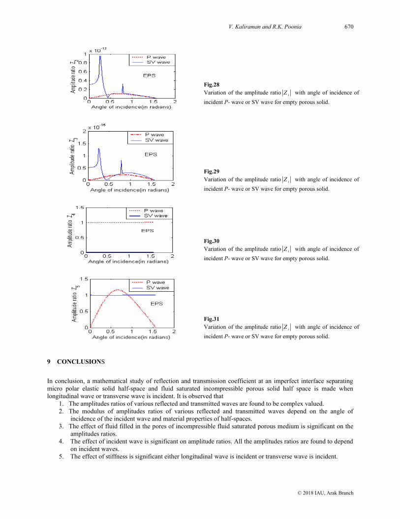
8.3 P-wave or SV wave incidence
Figs. (22) -(26) depicts the effect of incident longitudinal and incident transverse wave on the variation of amplitude
ratios. From these figures it is very clear that the amplitude ratios depend on incident wave. Also, the amplitude
ratios are small for incident P- wave in comparison to SV wave except for modulus of amplitude ratio of reflected
P-wave i.e. 4Z . Effect of incident longitudinal or incident transverse wave on the variation of amplitude ratios in
case of empty porous solid is shown in Figs. (27) - (31). In these figures, the modulus of amplitude ratios for
transmitted waves, are large in case of SV wave incidence and small for reflected waves.
Fig.22
Variation of the amplitude ratio iZ , i=1, 2,…,5 with angle of
incidence of incident P- wave or SV wave.

669 Elastic Wave Propagation at Imperfect Boundary of Micro polar….
© 2018 IAU, Arak Branch
Fig.23
Variation of the amplitude ratio iZ , i=1, 2,…,5 with angle of
incidence of incident P-wave or SV wave.
Fig.24
Variation of the amplitude ratio iZ , i=1, 2,…,5 with angle of
incidence of incident P- wave or SV wave.
Fig.25
Variation of the amplitude ratio iZ , i=1, 2,…,5 with angle of
incidence of incident P- wave or SV wave.
Fig.26
Variation of the amplitude ratio iZ , i=1, 2,…,5 with angle of
incidence of incident P- wave or SV wave.
Fig.27
Variation of the amplitude ratio iZ with angle of incidence of
incident P- wave or SV wave for empty porous solid.
V. Kaliraman and R.K. Poonia 670
© 2018 IAU, Arak Branch
Fig.28
Variation of the amplitude ratio iZ with angle of incidence of
incident P- wave or SV wave for empty porous solid.
Fig.29
Variation of the amplitude ratio iZ with angle of incidence of
incident P- wave or SV wave for empty porous solid.
Fig.30
Variation of the amplitude ratio iZ with angle of incidence of
incident P- wave or SV wave for empty porous solid.
Fig.31
Variation of the amplitude ratio iZ with angle of incidence of
incident P- wave or SV wave for empty porous solid.
9 CONCLUSIONS
In conclusion, a mathematical study of reflection and transmission coefficient at an imperfect interface separating
micro polar elastic solid half-space and fluid saturated incompressible porous solid half space is made when
longitudinal wave or transverse wave is incident. It is observed that
1. The amplitudes ratios of various reflected and transmitted waves are found to be complex valued.
2. The modulus of amplitudes ratios of various reflected and transmitted waves depend on the angle of
incidence of the incident wave and material properties of half-spaces.
3. The effect of fluid filled in the pores of incompressible fluid saturated porous medium is significant on the
amplitudes ratios.
4. The effect of incident wave is significant on amplitude ratios. All the amplitudes ratios are found to depend
on incident waves.
5. The effect of stiffness is significant either longitudinal wave is incident or transverse wave is incident.

671 Elastic Wave Propagation at Imperfect Boundary of Micro polar….
© 2018 IAU, Arak Branch
The model presented in this paper is one of the more realistic forms of the Earth models. The present theoretical
results may provide useful information for experimental scientists/researchers/seismologists working in the area of
wave propagation in micropolar elastic solid and fluid saturated incompressible porous solid.
REFERENCES
[1] Barak M.S., Kaliraman V., 2017, Reflection and refraction phenomena of elastic wave propagating through imperfect
interface of solids, International Journal of Statistika and Mathematika 24(1): 01-11.
[2] Barak M.S., Kaliraman V., 2018, Propagation of elastic waves at micro polar viscoelastic solid/fluid saturated
incompressible porous solid interface, International Journal of Computational Methods 15(1): 1850076(1-19).
[3] Barak M.S., Kaliraman V., 2018, Reflection and transmission of elastic waves from an imperfect boundary between
micro polar elastic solid half space and fluid saturated porous solid half space, Mechanics of Advanced Materials and
Structures 2018: 1-8.
[4] Bowen R.M., 1980, Incompressible porous media models by use of the theory of mixtures, International Journal of
Engineering Science 18: 1129-1148.
[5] De Boer R., Liu Z., 1994, Plane waves in a semi-infinite fluid saturated porous medium, Transport in Porous Media
16(2): 147-173.
[6] De Boer R., Didwania A.K., 2004, Two phase flow and capillarity phenomenon in porous solid- A Continuum
Thermomechanical Approach, Transport in Porous Media 56: 137-170.
[7] De Boer R., Ehlers W., 1990, The development of the concept of effective stress, Acta Mechanica 83: 77-92.
[8] De Boer R., Ehlers W., 1990, Uplift friction and capillarity-three fundamental effects for liquid-saturated porous solids,
International Journal of Solids and Structures 26: 43-47.
[9] De Boer R., Ehlers W., Liu Z., 1993, One-dimensional transient wave propagation in fluid-saturated incompressible
porous media, Archive of Applied Mechanics 63(1): 59-72.
[10] Eringen A.C., Suhubi E.S., 1964, Nonlinear theory of simple micro-elastic solids I, International Journal of
Engineering Science 2: 189-203.
[11] Eringen A.C., 1968, Linear theory of micro polar elasticity, International Journal of Engineering Science 5: 191-204.
[12] Gautheir R.D., 1982, Experimental Investigations on Micro polar Media, Mechanics of Micro polar Media, World
Scientific, Singapore.
[13] Kaliraman V., 2016, Propagation of P and SV waves through loosely bonded solid/solid interface, International
Journal of Mathematics Trends and Technology 52(6): 380-392.
[14] Kumar R., Madan D.K., Sikka J.S., 2014, Shear wave propagation in multilayered medium including an irregular fluid
saturated porous stratum with rigid boundary, Advances in Mathematical Physics 2014: 163505.
[15] Kumar R., Madan D.K., Sikka J.S., 2015, Wave propagation in an irregular fluid saturated porous anisotropic layer
sandwiched between a homogeneous layer and half space, Wseas Transactions on Applied and Theoretical Mechanics
10: 62-70.
[16] Kumar R., Hundal B.S., 2007, Surface wave propagation in fluid-saturated incompressible porous medium, Sadhana 32
(3): 155-166.
[17] Kumar R., Chawla V., 2010, Effect of rotation and stiffness on surface wave propagation in elastic layer lying over a
generalized thermo-diffusive elastic half-space with imperfect boundary, Journal of Solid Mechanics 2(1): 28-42.
[18] Kumar R., Barak M., 2007, Wave propagation in liquid-saturated porous solid with micro polar elastic skeleton at
boundary surface, Applied Mathematics and Mechanics 28(3): 337-349.
[19] Kumari N., 2014, Reflection and transmission of longitudinal wave at micro polar viscoelastic solid/fluid saturated
incompressible porous solid interface, Journal of Solid Mechanics 6(3): 240-254.
[20] Kumari N., 2014, Reflection and transmission phenomenon at an imperfect boundary of viscoelastic solid and fluid
saturated incompressible porous solid, Bulletin of Mathematics and Statistics Research 2(3): 306-319.
[21] Liu Z., 1999, Propagation and evolution of wave fronts in two-phase porous media, Transport in Porous Media 34:
209-225.
[22] Madan D.K., Kumar R., Sikka J.S., 2014, Love wave propagation in an irregular fluid saturated porous anisotropic
layer with rigid boundary, Journal of Applied Sciences Research 10(4): 281 - 287.
[23] Parfitt V.R., Eringen A.C., 1969, Reflection of plane waves from the flat boundary of a micro polar elastic half-space,
Journal of the Acoustical Society of America 45: 1258-1272.
[24] Singh B., Kumar R., 2007, Wave reflection at viscoelastic-micro polar elastic interface, Applied Mathematics and
Computation 185: 421-431.
[25] Tajuddin M., Hussaini S.J., 2006, Reflection of plane waves at boundaries of a liquid filled poroelastic half-space,
Journal Applied Geophysics 58: 59-86.
[26] Tomar S.K., Gogna M.L., 1992, Reflection and refraction of longitudinal micro rotational wave at an interface between
two different micro polar elastic solids in welded contact, International Journal of Engineering Science 30: 1637-1646.
[27] Tomar S.K., Kumar R., 1995, Reflection and refraction of longitudinal displacement wave at a liquid micro polar solid
interface, International Journal Engineering Sciences 33: 1507-1515.