journal of materials chemistry c - jiangnan.edu.cn
TRANSCRIPT

Polyimide-based graphene composite foamswith hierarchical impedance gradient for efficientelectromagnetic absorption†
Lei Pu,a Shuangshuang Li,a Yawei Zhang,a Haiyan Zhu,a Wei Fan, b Piming Ma, a
Weifu Dong, a Zicheng Wang *a and Tianxi Liu*a
The development of high-performance microwave absorption materials with strong absorption capacity
and broad bandwidth is highly desirable in the field of electromagnetic pollution protection. Herein,
polyimide/graphene composite foam with a multi-hierarchical impedance gradient structure has been
precisely designed and controllably constructed by two-step vacuum impregnation, which effectively
facilitates further attenuation of electromagnetic waves entering the graphene skeleton due to the
generation of interfacial polarization relaxation and internal multiple reflection/scattering, thereby
endowing it with excellent broadband microwave absorption performance. Meanwhile, the microwave
absorption performance can be controllably adjusted by optimizing the impedance gradient of the skeleton.
As a result, the optimized PI–GP–rGO composite foam exhibits a minimum reflection loss of �32.87 dB with
an effective bandwidth of 6.22 GHz (8.26–14.48 GHz) at 10.39 GHz when the thickness is 4.0 mm.
Introduction
With the development of information technology, a series ofnew electronic devices have shown explosive growth. Over time,electromagnetic radiation has become a new source of environ-mental pollution, which not only seriously affects the control ofthe electronic equipment, but also endangers the health of theorganisms.1–3 In addition, the continuous development ofmilitary radar has put forward higher requirements for weap-ons and equipment to avoid electronic reconnaissance andimprove survivability on the battlefield. Therefore, the devel-opment of high-performance microwave absorption (MA) mate-rials with a strong absorption capacity and a broad bandwidthhas become particularly urgent in the field of electromagneticpollution protection and radar stealth.4–11
In the past few years, porous carbon materials have beenwidely used in the field of electromagnetic protection dueto their porous or hollow microstructure and the excellentelectrical conductivity of skeletons.12–17 Because of thepresence of the porous structure, random electromagnetic
reflection/scattering would repeatedly occur at the interfacesof the cell wall, resulting in the transfer of electromagneticenergy to be dissipated as heat in the form of microcurrent. Forexample, Song et al. prepared a highly ordered porous carbon(HOPC) material and the minimum reflection loss (RLmin)value of the HOPC/wax composite reaches �18 dB at13 GHz.18 Wang et al. used the coal liquefaction residue as acarbon source to synthesize three-dimensional (3D) carbonfoam through a simple template method.19 The sample exhib-ited a broad effective absorption bandwidth (RL o �10 dB) ofup to 5.8 GHz. However, to date, porous carbon-based MAmaterials mainly rely on the multiple reflections between porestructures to achieve attenuation of incident electromagneticwaves (EMWs), and rarely involve the effect of impedancedistribution/gradient on the dissipation of electromagneticwaves entering the conductive skeleton.20–24
In this work, polyimide/graphene composite foam with amulti-hierarchical impedance gradient structure has been pre-cisely designed and controllably constructed by two-stepvacuum impregnation. Due to the superior thermal stabilityand mechanical strength, polyimide (PI) foam is employed asa 3D porous skeleton and subsequently coated with reducedgraphene oxide/polyimide (GP) and reduced graphene oxide(rGO) as the second and third layers, respectively, resultingin the PI–GP–rGO composite foam. The multi-hierarchicalstructure leads to the formation of a three-level impedancegradient, which effectively facilitates further attenuation ofelectromagnetic waves entering the graphene skeleton due to
Cite this: J. Mater. Chem. C, 2021,
9, 2086
a The Key Laboratory of Synthetic and Biological Colloids, Ministry of Education,
Institute of Nanocomposites and Energy Materials, School of Chemical and
Material Engineering, Jiangnan University, 214122 Wuxi, Jiangsu, P. R. China.
E-mail: [email protected], [email protected] State Key Laboratory for Modification of Chemical Fibers and Polymer Materials,
College of Materials Science and Engineering, Donghua University, Shanghai
201620, P. R. China
† Electronic supplementary information (ESI) available. See DOI: 10.1039/d0tc04951d
Received 19th October 2020,Accepted 20th December 2020
DOI: 10.1039/d0tc04951d
rsc.li/materials-c
2086 | J. Mater. Chem. C, 2021, 9, 2086�2094 This journal is The Royal Society of Chemistry 2021
Journal ofMaterials Chemistry C
PAPER
Publ
ishe
d on
22
Dec
embe
r 20
20. D
ownl
oade
d by
Jia
ngna
n U
nive
rsity
on
3/3/
2021
3:0
5:20
AM
.
View Article OnlineView Journal | View Issue

the generation of interface polarization and internal multiplereflection/scattering, thereby endowing the composite foamwith excellent broadband microwave absorption performancein comparison with the monotonous graphene foam. Mean-while, the microwave absorption performance can be effectivelyadjusted by controlling the impedance gradient of the skeleton.
ExperimentalMaterials
Graphite powder (325 mesh) was obtained from Qingdao Jin RiLai Graphite Co. Ltd (Qingdao, China). Concentrated sulfuric acid(H2SO4, 98%), phosphoric acid (H3PO4), hydrochloric acid (HCl,37%), potassium permanganate (KMnO4, Z99.5%), pyromelliticdianhydride (PMDA, Z98.5%), 4,40-oxydianiline (ODA, Z98.0%),triethylamine (TEA 99%) and N,N-dimethylacetamide (DMAc,99%) were purchased from Sinopharm Chemical Reagent Co.,Ltd. All commercial reagents in this study were of analytical gradeand used without further purification.
Synthesis of graphene oxide (GO) and polyamide acid (PAA)
Graphite flakes were oxidized using the improved Hummers’method.25,26 Water-soluble poly(amic acid) (PAA) was preparedthrough the condensation polymerization reaction of PMDAand ODA in an equimolar ratio using DMAc. Then, TEA was usedas the hydrophilic surface modifier to prepare PAA salt. Theviscous liquid was decanted with deionized water and repeatedlywashed to remove the solvent and unreacted raw materials. Afterfreeze-drying, the water-soluble PAA was obtained.
Preparation of polyimide/graphene composite foams with ahierarchical structure
As shown in Scheme 1, 0.15 g of TEA and 0.3 g of PAA were fullydissolved in 10 mL of deionized water to obtain a PAA sol whichwas then kept at 4 1C for 24 h to obtain the PAA hydrogel. ThePAA hydrogel was freeze-dried and heat-treated at 300 1C for 2 hto complete the imidization process and obtain the PI foam.
The PI foam was used as a skeleton and vacuum-impregnatedwith a mixed solution of GO/PAA at different concentration ratios.Subsequently, the mixture was taken out for the same freeze-drying and heat treatment to obtain the composite foam with a
bilayer structure (PI–GPx, where x represents the content of GO inGO/PAA, as displayed in Table 1). Then, the PI–GPx was immersedin GO dispersions of 4 mg mL�1 using the vacuum impregnationprocess. Finally, the mixture was taken out for freeze-drying andthermal treatment to obtain the multi-hierarchical composite foamwith a trilayer structure (PI–GPx–rGO). Here, rGO refers to reducedgraphene oxide originating from the thermal reduction of GO.
Characterization
Scanning electron microscopy (SEM) images were taken with aHitachi S-4800 cold field-emission scanning electron micro-scope operated at 30 kV. X-ray diffraction (XRD) patterns werecollected using a Bruker D8 X-ray diffractometer with a Cu KaX-ray source (l = 1.5418 Å). Thermal gravimetric analysis (TGA)was carried out by using a TGA/DSC1/1100SF system under a N2
atmosphere at a heating rate of 10 1C min�1. The mechanicalproperties were recorded using an electronic universal testingmachine (UTM2203, load cell = 200 N, Shenzhen Suns TechnologyStock Co. Ltd, China), and the results are exhibited in Fig. S9(ESI†). The electromagnetic parameters of the foams weremeasured using a vector network analyzer (Agilent 8720ET) at0.5–18 GHz. The testing samples were fabricated by vacuumimpregnation with melting paraffin and cut into standardcoaxial rings with an outer diameter of 7.0 mm and an innerdiameter of 3.0 mm, and the percentage of paraffin in thesamples was B85 wt%.
Results and discussionStructure and morphology of composite foams
The SEM images of composite foams are shown in Fig. 1. Anisotropic macroporous structure for PI foam with an average
Scheme 1 Preparation of PI–GPx–rGO composite foams with a multi-hierarchical structure.
Table 1 Composition of polyimide/graphene composite foams
No.GO : PAA(mg mL�1) Name (bilayer)
GO(mg mL�1) Name (trilayer)
1 0 : 0 PI 0 PI2 0 : 4 PI–PI 4 PI–PI–rGO3 4 : 8 PI–GP1/3 4 PI–GP1/3–rGO4 4 : 4 PI–GP1/2 4 PI–GP1/2–rGO5 4 : 2 PI–GP2/3 4 PI–GP2/3–rGO6 4 : 0 PI–rGO 4 PI–rGO–rGO
This journal is The Royal Society of Chemistry 2021 J. Mater. Chem. C, 2021, 9, 2086�2094 | 2087
Paper Journal of Materials Chemistry C
Publ
ishe
d on
22
Dec
embe
r 20
20. D
ownl
oade
d by
Jia
ngna
n U
nive
rsity
on
3/3/
2021
3:0
5:20
AM
. View Article Online

pore size of ca. 100 mm can be obviously observed in Fig. 1(a).Meanwhile, the pore size of PI–GP1/2 and PI–GP1/2–rGO gradu-ally decreases as displayed in Fig. 1(b) and (c), respectively,which can be ascribed to the effective loading of GO/PAA andGO, thereby visually confirming the successful construction ofthe hierarchical skeleton structure. Moreover, the lamellarstructure in the pores of PI-GP1/2 and PI–GP1/2–rGO becomesmuch more obvious (Fig. 1 and Fig. S1, ESI†). The growth of icecrystals is guided orderly by the rigid GO nanosheets on thepore walls of composite foams along the interlayer duringfreeze-drying.27 In addition, the GO nanosheets begin to bendand be stacked into layers when the oxygen functional groupsof GO are removed during the thermal treatment.28,29 As aresult, the morphology of PI–GP1/2–rGO exhibits a distinctivelamellar structure in comparison with those of PI and PI–GP1/2.Other PI–GPx and PI–GPx–rGO with different GO contentsexhibit similar morphology as shown in Fig. S2 (ESI†), whichonce again verifies the controllable construction of compositefoams with a hierarchical structure.
TGA was employed to explore the microstructural changes ofGO sheets and PAA chains in the composite foams. As shown inFig. 2(a)–(c), after thermal treatment at 300 1C for 2 h, thethermal stabilities of GO, PAA and GO/PAA exhibit significantimprovement. It can be attributed to the decomposition ofunstable functional groups in GO sheets and the dehydration ofPAA chains, thereby confirming the effectiveness of the thermaltreatment on the thermal reduction of GO sheets and theimidization of PAA chains. Furthermore, the thermal stabilityof composite foams has been prominently enhanced after rGO/PI and rGO are loaded on PI and PI–GP1/2. As depicted inFig. 2(d), the initial decomposition temperatures (T5 wt%, corres-ponding to the temperature with a 5% weight loss) of PI,PI–GP1/2 and PI–GP1/2–rGO are 487.9 1C, 517.7 1C and526.3 1C, respectively. At the same time, the residual yields ofPI, PI–GP1/2 and PI–GP1/2–rGO are 49.9 wt%, 52.3 wt% and 56.4wt% at 800 1C, respectively. In addition, for PI–GPx and PI–GPx–rGO composite foams with different GO contents in GO/PAAx
of the second layer, similar tendency for T5 wt% and residualyield can be observed in Fig. S3 (ESI†). As shown in theSEM observation (Fig. 1), rGO/PI and rGO are uniformly dis-tributed on the surface of the composite foams. Moreover, therGO sheets exhibit good thermal stability, which can protectthe foam skeleton from being decomposed too fast during thethermal treatment.29,30 More importantly, the large evolution in
thermal stability indirectly confirms that the multi-hierarchicalskeleton structure has been successfully constructed in thecomposite foams.
The microstructural changes produced during the thermaltreatment could be also identified by XRD. As shown inFig. 3(a), GO powder exhibits a sharp diffraction peak indexedto (002) centered at 10.81. After incorporation with PAA, a well-defined diffraction peak of the obtained GO/PAA1/2 shifts to alower angle of 8.31. Moreover, the characteristic peak of PAAshifted from 17.01 to 16.61, which can be obviously observed inFig. 3(c),31,32 indicating that the introduction of PAA chainsfacilitates exfoliation of GO sheets effectively. After beingtreated at 300 1C, the stacking peak of GO disappears, while anew broad peak at around 23.91 arises as shown in Fig. 3(c),corresponding to the (001) plane of reduced graphene oxide(Fig. 3(a)), which also verifies the effectiveness of the thermaltreatment on the reduction of GO in the GO/PAA1/2 system.Meanwhile, it is worth noting that the characteristic peak of theobtained PI in rGO/PI shifts to a lower angle of B15.01. For thecomposite foams with a hierarchical structure, the diffractionpeak (17.11) of PI in PI–GP1/2 exhibits a superimposed effect ofPI (17.91) and rGO/PI1/2 (B15.01) as shown in Fig. 3(d), indicat-ing the successful construction of bilayer composite foams. Incomparison with pure PI foam, a new shoulder peak (located atB25.01) in PI–GP1/2 can be attributed to the characteristicdiffraction of graphene. For the PI–GP1/2–rGO, the shoulderpeak strengthens, whereas the characteristic peak of PI weak-ens due to the loading of the third-layer rGO on the surface ofthe PI–GP1/2 foam, demonstrating the successful constructionof multi-hierarchical composite foams. Furthermore, the otherPI–GPx and PI–GPx–rGO with different GO contents exhibitsimilar results as shown in Fig. S4 (ESI†), which once againverifies the controllable construction of composite foams with ahierarchical structure.
Permittivity properties of composite foams
The MA characteristics of non-magnetic absorbing materialsare highly dependent on their permittivity parameters as shownin Fig. 4 and Fig. S5 (ESI†). Among the complex permittivity(er = e0 � je00), the real part e’ represents the storage modulus of theMA materials, while the imaginary part e00 represents the lossmodulus of the MA materials.33 Fig. 4(a)–(c) show the graduallyincreasing complex permittivity (e0, and e00) and dielectric losstangent (tande = e00/e0) of PI, PI–GP1/2, and PI–GP1/2–rGO in the
Fig. 1 SEM images of polyimide/graphene composite foams with different hierarchical structures: (a) PI; (b) PI–GP1/2; and (c) PI–GP1/2–rGO (The smallpicture embedded in the upper right corner is a partial magnification of 500 times).
2088 | J. Mater. Chem. C, 2021, 9, 2086�2094 This journal is The Royal Society of Chemistry 2021
Journal of Materials Chemistry C Paper
Publ
ishe
d on
22
Dec
embe
r 20
20. D
ownl
oade
d by
Jia
ngna
n U
nive
rsity
on
3/3/
2021
3:0
5:20
AM
. View Article Online

frequency range of 0.5–18 GHz, verifying the formation of thethree-level impedance gradient of multi-hierarchical compositefoams. Meanwhile, the impedance gradient of PI–GPx–rGO canbe controllably adjusted by optimizing the permittivity properties ofGO/PAAx with different GO contents in the second layer, as shown inFig. 4(d)–(f). It is worth noting that the permittivity of PI–GP1/2 andPI–GP1/2–rGO is higher than that of pure rGO, which can beattributed to the successive pushing of the growth of ice crystals
during the freeze-drying process, leading to the formation of morecompact graphene conductive networks in PI–GP1/2 and PI–GP1/2–rGO.
In order to further identify the factors contributing tothe permittivity properties, the plots of e00 versus e0 (Cole–Colesemicircles) for the composite foams are shown in Fig. S6(ESI†). As for PI foam, there are several semicircles inFig. S6(a) (ESI†), indicating the existence of orientation polar-ization processes in polyimide chains. After incorporation
Fig. 2 TGA curves of (a) GO and rGO, (b) PAA and PI, and (c) GO/PAA1/2 and rGO/PI1/2; (d) polyimide/graphene composite foams with differenthierarchical structures: PI, PI–GP1/2, and PI–GP1/2–rGO.
Fig. 3 (a) XRD curves of (a) GO and rGO, (b) PAA and PI, and (c) GO/PAA1/2 and rGO/PI1/2; (d) polyimide/graphene composite foams with differenthierarchical structures: PI, PI–GP1/2, and PI–GP1/2–rGO.
This journal is The Royal Society of Chemistry 2021 J. Mater. Chem. C, 2021, 9, 2086�2094 | 2089
Paper Journal of Materials Chemistry C
Publ
ishe
d on
22
Dec
embe
r 20
20. D
ownl
oade
d by
Jia
ngna
n U
nive
rsity
on
3/3/
2021
3:0
5:20
AM
. View Article Online

with rGO/PI1/2, the plot of PI–GP1/2 exhibits multiple semicir-cles distinguished from PI foam, which may be caused by theinterface polarization relaxation existing in the rGO/PI1/2 as wellas between PI and rGO/PI1/2, being beneficial to the attenuationof microwave energy. Moreover, it is worth noting that con-ductivity loss can be also confirmed by the presence of the linetail in the plot (Fig. S6(b), ESI†), which mainly arises from theformation of a conductive rGO network in the second layer forPI–GP1/2.34 More importantly, with the loading of the third-layerof rGO, the length of the line tail further extends to a higherposition as shown in Fig. S6(c) (ESI†), implying the enhance-ment of conductive loss. It is consistent with the increasingtendency of electrical conductivity for the hierarchical compo-site foams as depicted in Fig. S6(d) (ESI†). The conductive lossplays a crucial role in microwave dissipation as time-dependentelectromagnetic field-induced currents occur in the conductivenetwork.12 Additionally, similar phenomena can be observedfor the other PI–GPx–rGO with different second layers (rGO/PIx,Fig. S6(e) and (f) (ESI†)). Therefore, the aforementioned resultsreveal that two main facts, including the interfacial polarizationrelaxation of multi-hierarchical structures and the conductiveloss of the rGO network, synergistically endow the PI–GPx–rGOcomposite foam with excellent dielectric loss.
Microwave absorption properties of composite foams
To investigate the microwave absorption performance of thefoams, the reflection loss (RL) of the incident electromagneticwave was calculated according to eqn (1) and (2):
RL dBð Þ ¼ 20 logZin � Z0
Zin þ Z0
�������� (1)
Zin ¼ Z0
ffiffiffiffiffimrer
rtanh j
2pfdc
� � ffiffiffiffiffiffiffiffimrerp
� �(2)
where mr and er are the relative permeability and permittivityof the composites, respectively, f is the microwave frequency,d is the thickness of the composites and c is the speed oflight.11,15,35 The values of reflection loss are displayed inFig. 5, 7 and Fig. S7, S8 (ESI†).
As shown in Fig. 5(d), the pure rGO foam has an RLmin valueof �14 dB when the absorber thickness and frequency are5 mm and 9.81 GHz, respectively. Its effective bandwidth (RL o�10 dB) is 3.73 GHz (8.16–11.89 GHz). However, the MAperformance of PI is poor over the entire frequency range(Fig. 5(a)). After being combined with rGO/PI1/2, the RLmin valueof the PI–GP1/2 foam can be effectively decreased to �20.15 dBat 8.16 GHz when the thickness is 5 mm (as displayed inFig. 5(b) and Fig. S7, ESI†). At this time, its effective bandwidthis 3.73 GHz (6.67–10.40 GHz). As for PI–GP1/2–rGO (Fig. 5(c) andFig. S7, ESI†), an RLmin value of �24.86 dB at 18.0 GHz with athickness of 2 mm is obtained, while the effective bandwidth isimproved to 3.97 GHz (14.03–18 GHz). In comparison with PI–GP1/2
and pure rGO foams, the conspicuous enhancement in absorptioncapacity and bandwidth can be attributed to the successfulconstruction of the three-level impedance gradient in the foam.
On one hand, the introduction of the third-layer rGO willpromote the formation of conductive networks on the surfaceof the PI–GP1/2 skeleton, leading to the generation of a strongrandom multiple reflection loss in the final composite foam.On the other hand, the effective construction of the three-levelimpedance gradient in PI–GP1/2–rGO will further improve theattenuation of electromagnetic waves entering the skeletonstructure interior (through the rGO on the surface) in compar-ison with the monotonous rGO foam.
Based on eqn (2), the normalized characteristic impedance(Z = |Zin/Z0|) can be calculated to evaluate the impedancematching of the composite foams.36 As a result, the two-dimensional (2D) impedance matching contour maps of
Fig. 4 The electromagnetic parameters of the composite foams: (a and d) the real parts of complex permittivity; (b and e) the imaginary parts ofcomplex permittivity; and (c and f) the dielectric loss tangent of the composite foams.
2090 | J. Mater. Chem. C, 2021, 9, 2086�2094 This journal is The Royal Society of Chemistry 2021
Journal of Materials Chemistry C Paper
Publ
ishe
d on
22
Dec
embe
r 20
20. D
ownl
oade
d by
Jia
ngna
n U
nive
rsity
on
3/3/
2021
3:0
5:20
AM
. View Article Online

PI–GP1/2–rGO and pure rGO with sample thickness and measure-ment frequency are exhibited in Fig. 6(a) and (b), respectively. Thecolor of sky blue represents the area in which Z equals 1. Therefore,achieving good impedance matching requires that the value of
Z is equal or close to 1. In comparison with rGO, PI–GP1/2–rGOexhibits conspicuous optimization in impedance matching dueto the introduction of the hierarchical structure (PI and GP1/2),meaning that the more incident electromagnetic waves could
Fig. 5 3D reflection loss maps of composite foams: (a) PI, (b) PI–GP1/2, (c) PI–GP1/2–rGO and (d) rGO.
Fig. 6 2D impedance matching contour maps (|Zin/Z0|) of the composite foams with different thicknesses from 0.5 GHz to 18 GHz: (a) PI–GP1/2–rGOand (b) rGO; (c) attenuation constants of the composite foams; and (d) illustration of EMW absorption mechanisms for the PI–GPx–rGO compositefoams.
This journal is The Royal Society of Chemistry 2021 J. Mater. Chem. C, 2021, 9, 2086�2094 | 2091
Paper Journal of Materials Chemistry C
Publ
ishe
d on
22
Dec
embe
r 20
20. D
ownl
oade
d by
Jia
ngna
n U
nive
rsity
on
3/3/
2021
3:0
5:20
AM
. View Article Online

enter the absorber. Meanwhile, the attenuation constant is alsoused to qualify the electromagnetic energy attenuation abilityof the absorber, which can be calculated using eqn (3):
a ¼ffiffiffi2p
pfc
ffiffiffiffiffiffiffiffiffiffiffiffiffiffiffiffiffiffiffiffiffiffiffiffiffiffiffiffiffiffiffiffiffiffiffiffiffiffiffiffiffiffiffiffiffiffiffiffiffiffiffiffiffiffiffiffiffiffiffiffiffiffiffiffiffiffiffiffiffiffiffiffiffiffiffiffiffiffiffiffiffiffiffiffiffiffiffiffiffiffiffiffiffiffim00e00 � m0e0ð Þ þ
ffiffiffiffiffiffiffiffiffiffiffiffiffiffiffiffiffiffiffiffiffiffiffiffiffiffiffiffiffiffiffiffiffiffiffiffiffiffiffiffiffiffiffiffiffiffiffiffiffiffiffiffiffiffiffiffiffiffim00e00 � m0e0ð Þ2þ m00e0 þ m0e00ð Þ2
qr(3)
As shown in Fig. 6(c), PI–GP1/2–rGO exhibits a higher EMWattenuation constant than the pure rGO foam, which is bene-ficial to enhance the attenuation of incident EMWs as much aspossible. As a consequence, the EMWs can be dissipated asintrinsic conductive/dielectric loss and multiple reflection/scat-tering between the internal interfaces of the composite skeletonas demonstrated in Fig. 6(d), thereby exhibiting an excellentmicrowave absorption performance.
Furthermore, on the basis of the same multi-hierarchicalconfiguration, the optimization of impedance gradient for thecomposite foams will become an efficient means for realizing the
controllable adjustment of microwave absorption performance.As shown in Fig. 7 and Fig. S8 (ESI†), with the decrease of GOcontent in the second-layer GO/PAAx, the RLmin value of PI–GPx–rGOshows a tendency to decrease from �12.47 dB (PI–GP2/3–rGO) to�24.86 dB (PI–GP1/2–rGO), and�32.87 dB (PI–GP1/3–rGO), whereasthe corresponding effective bandwidth decreases from 4.51 GHz to3.97 GHz, and then increases to a higher value of 6.22 GHz.
Compared with PI–GP1/2–rGO and PI–GP2/3–rGO, theattenuation constant of PI–GP1/3–rGO is lower than those ofPI–GP1/2–rGO and PI–GP2/3–rGO with the increasing GO con-tent in the second-layer GPx (Fig. 8(d)), whereas the impedancematching for PI–GP1/3–rGO shows a reverse improvement asdisplayed in Fig. 8(a)–(c). Under the synergistic effect of impe-dance matching and attenuation characteristics, a valley of MAperformance (corresponding effective bandwidth) arises for thesample of PI-GP1/2–rGO (3.97 GHz), which is lower than thatof PI–GP2/3–rGO (4.51 GHz) and PI–GP1/3–rGO (6.22 GHz).
Fig. 7 3D reflection loss maps of composite foams: (a) PI–GP1/3–rGO, (b) PI–GP1/2–rGO and (c) PI–GP2/3–rGO.
Fig. 8 2D impedance matching contour maps (|Zin/Z0|) of composite foams with different thicknesses from 0.5 GHz to 18 GHz: (a) PI–GP1/3–rGO;(b) PI–GP1/2–rGO and (c) PI–GP2/3–rGO. (d) Attenuation constants of the composite foams.
2092 | J. Mater. Chem. C, 2021, 9, 2086�2094 This journal is The Royal Society of Chemistry 2021
Journal of Materials Chemistry C Paper
Publ
ishe
d on
22
Dec
embe
r 20
20. D
ownl
oade
d by
Jia
ngna
n U
nive
rsity
on
3/3/
2021
3:0
5:20
AM
. View Article Online
Therefore, it can be concluded that, under the synergistic effectof impedance matching and attenuation characteristics, goodimpedance matching will play a crucial role in facilitating theentry of more incident electromagnetic waves into the absorberand the dissipation of incident EMWs as much as possible.
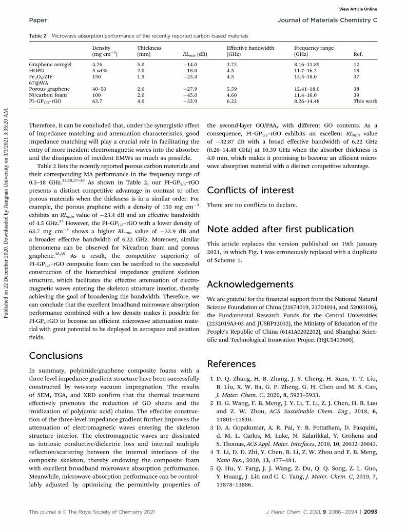
Table 2 lists the recently reported porous carbon materials andtheir corresponding MA performance in the frequency range of0.5–18 GHz.12,18,37–39 As shown in Table 2, our PI–GP1/3–rGOpresents a distinct competitive advantage in contrast to otherporous materials when the thickness is in a similar order. Forexample, the porous graphene with a density of 150 mg cm�3
exhibits an RLmin value of �23.4 dB and an effective bandwidthof 4.5 GHz.37 However, the PI–GP1/3–rGO with a lower density of63.7 mg cm�3 shows a higher RLmin value of �32.9 dB anda broader effective bandwidth of 6.22 GHz. Moreover, similarphenomena can be observed for Ni/carbon foam and porousgraphene.38,39 As a result, the competitive superiority ofPI–GP1/3–rGO composite foam can be ascribed to the successfulconstruction of the hierarchical impedance gradient skeletonstructure, which facilitates the effective attenuation of electro-magnetic waves entering the skeleton structure interior, therebyachieving the goal of broadening the bandwidth. Therefore, wecan conclude that the excellent broadband microwave absorptionperformance combined with a low density makes it possible forPI-GPx-rGO to become an efficient microwave attenuation mate-rial with great potential to be deployed in aerospace and aviationfields.
Conclusions
In summary, polyimide/graphene composite foams with athree-level impedance gradient structure have been successfullyconstructed by two-step vacuum impregnation. The resultsof SEM, TGA, and XRD confirm that the thermal treatmenteffectively promotes the reduction of GO sheets and theimidization of poly(amic acid) chains. The effective construc-tion of the three-level impedance gradient further improves theattenuation of electromagnetic waves entering the skeletonstructure interior. The electromagnetic waves are dissipatedas intrinsic conductive/dielectric loss and internal multiplereflection/scattering between the internal interfaces of thecomposite skeleton, thereby endowing the composite foamwith excellent broadband microwave absorption performance.Meanwhile, microwave absorption performance can be control-lably adjusted by optimizing the permittivity properties of
the second-layer GO/PAAx with different GO contents. As aconsequence, PI–GP1/3–rGO exhibits an excellent RLmin valueof �32.87 dB with a broad effective bandwidth of 6.22 GHz(8.26–14.48 GHz) at 10.39 GHz when the absorber thickness is4.0 mm, which makes it promising to become an efficient micro-wave absorption material with a distinct competitive advantage.
Conflicts of interest
There are no conflicts to declare.
Note added after first publication
This article replaces the version published on 19th January2021, in which Fig. 1 was erroneously replaced with a duplicateof Scheme 1.
Acknowledgements
We are grateful for the financial support from the National NaturalScience Foundation of China (21674019, 21704014, and 52003106),the Fundamental Research Funds for the Central Universities(2232019A3-03 and JUSRP12032), the Ministry of Education of thePeople’s Republic of China (6141A0202202), and Shanghai Scien-tific and Technological Innovation Project (18JC1410600).
References
1 D. Q. Zhang, H. B. Zhang, J. Y. Cheng, H. Raza, T. T. Liu,B. Liu, X. W. Ba, G. P. Zheng, G. H. Chen and M. S. Cao,J. Mater. Chem. C, 2020, 8, 5923–5933.
2 H. G. Wang, F. B. Meng, J. Y. Li, T. Li, Z. J. Chen, H. B. Luoand Z. W. Zhou, ACS Sustainable Chem. Eng., 2018, 6,11801–11810.
3 D. A. Gopakumar, A. R. Pai, Y. B. Pottathara, D. Pasquini,d. M. L. Carlos, M. Luke, N. Kalarikkal, Y. Grohens andS. Thomas, ACS Appl. Mater. Interfaces, 2018, 10, 20032–20043.
4 T. Li, D. D. Zhi, Y. Chen, B. Li, Z. W. Zhou and F. B. Meng,Nano Res., 2020, 13, 477–484.
5 Q. Hu, Y. Fang, J. J. Wang, Z. Du, Q. Q. Song, Z. L. Guo,Y. Huang, J. Lin and C. C. Tang, J. Mater. Chem. C, 2019, 7,13878–13886.
Table 2 Microwave absorption performance of the recently reported carbon-based materials
Density(mg cm�3)
Thickness(mm) RLmin (dB)
Effective bandwidth(GHz)
Frequency range(GHz) Ref.
Graphene aerogel 4.76 5.0 �14.0 3.73 8.16–11.89 12HOPG 5 wt% 2.0 �18.0 4.5 11.7–16.2 18Fe3O4/ZIF-67@WA
150 1.5 �23.4 4.5 13.5–18.0 37
Porous graphene 40–50 2.0 �27.9 5.59 12.41–18.0 38Ni/carbon foam 100 2.0 �45.0 4.60 11.4–16.0 39PI–GP1/3–rGO 63.7 4.0 �32.9 6.22 8.26–14.48 This work
This journal is The Royal Society of Chemistry 2021 J. Mater. Chem. C, 2021, 9, 2086�2094 | 2093
Paper Journal of Materials Chemistry C
Publ
ishe
d on
22
Dec
embe
r 20
20. D
ownl
oade
d by
Jia
ngna
n U
nive
rsity
on
3/3/
2021
3:0
5:20
AM
. View Article Online
6 W. C. Li, L. Y. Xu, X. Zhang, Y. Gong, Y. Ying, J. Yu,J. W. Zheng, L. Qiao and S. L. Che, Compos. Commun.,2020, 19, 182–188.
7 Z. Xiang, J. Xiong, B. W. Deng, E. B. Cui, L. Z. Yu, Q. W. Zeng,K. Pei, R. C. Che and W. Lu, J. Mater. Chem. C, 2020, 8,2123–2134.
8 L. Y. Liang, R. S. Yang, G. J. Han, Y. Z. Feng, B. Zhao,R. Zhang, Y. M. Wang and C. T. Liu, ACS Appl. Mater.Interfaces, 2020, 12, 2644–2654.
9 Y. Y. Wang, Z. H. Zhou, C. G. Zhou, W. J. Sun, J. F. Gao,K. Dai, D. X. Yan and Z. M. Li, ACS Appl. Mater. Interfaces,2020, 12, 8704–8712.
10 M. Hamidinejad, B. Zhao, A. Zandieh, N. Moghimian,T. Filleter and C. B. Park, ACS Appl. Mater. Interfaces, 2018,10, 30752–30761.
11 X. L. Li, X. W. Yin, H. L. Xu, M. K. Han, M. H. Li, S. Liang,L. F. Cheng and L. T. Zhang, ACS Appl. Mater. Interfaces,2018, 10, 34524–34533.
12 Z. C. Wang, R. B. Wei, J. W. Gu, H. Liu, C. T. Liu, C. J. Luo,J. Kong, Q. Shao, N. Wang, Z. H. Guo and X. B. Liu, Carbon,2018, 139, 1126–1135.
13 F. B. Meng, H. G. Wang, W. Wei, Z. J. Chen, T. Li, C. Y. Li,Y. Xuan and Z. W. Zhou, Nano Res., 2018, 11, 2847–2861.
14 M. Antunes and J. I. Velasco, Prog. Polym. Sci., 2014, 39,486–509.
15 B. Zhao, J. S. Deng, C. X. Zhao, C. D. Wang, Y. G. Chen,M. Hamidinejad, R. S. Li and C. B. Park, J. Mater. Chem. C,2020, 8, 58–70.
16 B. Zhao, R. M. Wang, Y. Li, Y. M. Ren, X. Li, X. Q. Guo,R. Zhang and C. B. Park, J. Mater. Chem. C, 2020, 8,7401–7410.
17 Y. Zhang, Y. Huang, H. H. Chen, Z. Y. Huang, Y. Yang,P. S. Xiao, Y. Zhou and Y. S. Chen, Carbon, 2016, 105, 438–447.
18 W. L. Song, M. S. Cao, L. Z. Fan, M. M. Lu, Y. Li, C. Y. Wangand H. F. Ju, Carbon, 2014, 77, 130–142.
19 S. Wang, N. Xiao, Y. Zhou, Z. Ling, M. Li and J. Qiu, Carbon,2016, 105, 224–226.
20 A. Sheng, W. Ren, Y. Q. Yang, D. X. Yan, H. J. Duan,G. Z. Zhao, Y. Q. Liu and Z. M. Li, Composites, Part A,2020, 129, 105692.
21 W. L. Song, C. C. Gong, H. M. Li, X. D. Cheng, M. J. Chen,X. J. Yuan, H. S. Chen, Y. Z. Yang and D. N. Fang, ACS Appl.Mater. Interfaces, 2017, 9, 36119–36129.
22 Y. D. Xu, Y. Q. Yang, D. X. Yan, H. J. Duan, G. Z. Zhao andY. Q. Liu, ACS Appl. Mater. Interfaces, 2018, 10, 19143.
23 X. L. Li, X. W. Yin, C. Q. Song, M. K. Han, H. L. Xu,W. Y. Duan, L. F. Cheng and L. T. Zhang, Adv. Funct. Mater.,2018, 28, 1803938.
24 H. J. Duan, H. X. Zhu, J. F. Gao, D. X. Yan, K. Dai, Y. Q. Yang,G. Z. Zhao, Y. Q. Liu and Z. M. Li, J. Mater. Chem. A, 2020, 8,9146–9159.
25 H. N. Li, L. Xu, S. Hansinee, W. Kimal and Y. Cheng,Compos. Commun., 2016, 1, 48–53.
26 C. Daniela, D. V. K. Marcano, J. M. Berlin, A. Sinitskii,Z. Z. Sun, A. Slesarev, L. B. Alemany, W. Lu andJ. M. Tour, ACS Nano, 2010, 4, 4806–4814.
27 L. Li, Y. Zhang, H. Y. Lu, Y. F. Wang, J. S. Xu, J. X. Zhu,C. Zhang and T. X. Liu, Nat. Commun., 2020, 11, 62.
28 K. P. Ruan, Y. Q. Guo, Y. S. Tang, Y. L. Zhang, J. N. Zhang,M. K. He, J. Kong and J. W. Gu, Compos. Commun., 2018, 10,68–72.
29 Y. Y. Wang, Z. H. Zhou, C. G. Zhou, W. J. Sun, J. F. Gao,K. Dai, D. X. Yan and Z. M. Li, ACS Appl. Mater. Interfaces,2020, 12, 8704–8712.
30 Y. C. Qing, Q. L. Wen, F. Luo and W. C. Zhou, J. Mater.Chem. C, 2016, 4, 4853–4862.
31 H. D. Huang, C. Y. Liu, D. Zhou, X. Jiang, G. J. Zhong,D. X. Yan and Z. M. Li, J. Mater. Chem. A, 2015, 3, 4983–4991.
32 J. W. Li, Y. Q. Ding, N. Yu, Q. Gao, X. Fan, X. Wei,G. C. Zhang, Z. L. Ma and X. H. He, Carbon, 2020, 158,45–54.
33 H. Kim, Y. Miura and C. W. Macosko, Chem. Mater., 2010,22, 3441–3450.
34 X. N. Chen, Y. Zhang, L. Tao, Q. Q. Nie, F. C. Meng,S. B. Zhu, L. Y. Cui and R. X. Huang, Carbon, 2020, 164,224–234.
35 P. A. Miles, W. B. Westphal and A. Von Hippel, Rev. Mod.Phys., 1957, 29, 279.
36 B. W. Deng, Z. Xiang, J. Xiong, Z. C. Liu, L. Z. Yu and W. Lu,Nano-Micro Lett., 2020, 12, 55.
37 L. L. Xu, Y. Xiong, B. K. Dang, Z. N. Ye, C. D. Jin, Q. F. Sunand X. H. Yu, Mater. Des., 2019, 182, 108006.
38 C. Chen, J. B. Xi, E. Z. Zhou, L. Peng, Z. C. Chen and C. Gao,Nano-Micro Lett., 2018, 10, 26.
39 H. B. Zhao, Z. B. Fu, H. B. Chen, M. L. Zhong andC. Y. Wang, ACS Appl. Mater. Interfaces, 2016, 8, 1468–1477.
2094 | J. Mater. Chem. C, 2021, 9, 2086�2094 This journal is The Royal Society of Chemistry 2021
Journal of Materials Chemistry C Paper
Publ
ishe
d on
22
Dec
embe
r 20
20. D
ownl
oade
d by
Jia
ngna
n U
nive
rsity
on
3/3/
2021
3:0
5:20
AM
. View Article Online