joint test protocol: environmentally friendly zirconium ... · compatibility with the current suite...
TRANSCRIPT
Joint Test Protocol: Environmentally Friendly Zirconium
Oxide Pretreatment Demonstration
by Fred L. Lafferman
ARL-MR-857 December 2013
Approved for public release; distribution unlimited.

NOTICES
Disclaimers
The findings in this report are not to be construed as an official Department of the Army position
unless so designated by other authorized documents.
Citation of manufacturer’s or trade names does not constitute an official endorsement or
approval of the use thereof.
Destroy this report when it is no longer needed. Do not return it to the originator.

Army Research Laboratory Aberdeen Proving Ground, MD 21005
ARL-MR-857 December 2013
Joint Test Protocol: Environmentally Friendly Zirconium
Oxide Pretreatment Demonstration
Fred L. Lafferman
Weapons and Materials Research Directorate, ARL
Approved for public release; distribution unlimited.

ii
REPORT DOCUMENTATION PAGE Form Approved
OMB No. 0704-0188 Public reporting burden for this collection of information is estimated to average 1 hour per response, including the time for reviewing instructions, searching existing data sources, gathering and maintaining the
data needed, and completing and reviewing the collection information. Send comments regarding this burden estimate or any other aspect of this collection of information, including suggestions for reducing the
burden, to Department of Defense, Washington Headquarters Services, Directorate for Information Operations and Reports (0704-0188), 1215 Jefferson Davis Highway, Suite 1204, Arlington, VA 22202-4302.
Respondents should be aware that notwithstanding any other provision of law, no person shall be subject to any penalty for failing to comply with a collection of information if it does not display a currently
valid OMB control number.
PLEASE DO NOT RETURN YOUR FORM TO THE ABOVE ADDRESS.
1. REPORT DATE (DD-MM-YYYY)
December 2013
2. REPORT TYPE
Final
3. DATES COVERED (From - To)
February 2013–July 2013
4. TITLE AND SUBTITLE
Joint Test Protocol: Environmentally Friendly Zirconium Oxide Pretreatment
Demonstration
5a. CONTRACT NUMBER
5b. GRANT NUMBER
5c. PROGRAM ELEMENT NUMBER
6. AUTHOR(S)
Fred L. Lafferman
5d. PROJECT NUMBER
WP-201318
5e. TASK NUMBER
5f. WORK UNIT NUMBER
7. PERFORMING ORGANIZATION NAME(S) AND ADDRESS(ES)
U.S. Army Research Laboratory
ATTN: RDRL-WMM-C
Aberdeen Proving Ground, MD 21005
8. PERFORMING ORGANIZATION REPORT NUMBER
ARL-MR-857
9. SPONSORING/MONITORING AGENCY NAME(S) AND ADDRESS(ES)
Environmental Security Technology Certification Program
4800 Mark Center Drive, Ste. 17D08
Alexandria, VA 22350-3605
10. SPONSOR/MONITOR'S ACRONYM(S)
ESTCP
11. SPONSOR/MONITOR'S REPORT NUMBER(S)
12. DISTRIBUTION/AVAILABILITY STATEMENT
Approved for public release; distribution unlimited.
13. SUPPLEMENTARY NOTES
14. ABSTRACT
There is a need to implement innovative and cost-effective replacement technologies to address the multiple health, safety,
and compliance issues associated with the use of zinc phosphate and chromate/chrome containing conversion coatings while
maintaining military readiness for national defense. The new technology must be compatible with original equipment
manufacturer/depot infrastructure to and with the current coatings and substrates used by the Department of Defense, and have
corrosion performance equivalent or better than current pretreatment technology. The objective of this program is to
demonstrate a novel zirconium-based pretreatment that will be environmentally acceptable, cost effective, and perform equal
to baseline pretreatments for multimetal application. The demonstration will be on a military asset coated and compatible with
the existing chemical agent–resistant coating system.
15. SUBJECT TERMS
zirconium oxide, pretreatment, chromate free, joint test protocol, multimetal
16. SECURITY CLASSIFICATION OF:
17. LIMITATION OF
ABSTRACT
UU
18. NUMBER OF PAGES
46
19a. NAME OF RESPONSIBLE PERSON
Fred L. Lafferman a. REPORT
Unclassified
b. ABSTRACT
Unclassified
c. THIS PAGE
Unclassified
19b. TELEPHONE NUMBER (Include area code)
(410) 306-1520 Standard Form 298 (Rev. 8/98)
Prescribed by ANSI Std. Z39.18

iii
Contents
List of Figures vi
List of Tables vi
Preface vii
1. Introduction 1
2. Performance and Testing Requirements 3
3. Test Descriptions 7
3.1 Neutral Salt Fog for Flat Panels (ASTM B 117) .............................................................9
3.1.1 Test Description ..................................................................................................9
3.1.3 Test Methodology ..............................................................................................10
3.1.2 Rationale ............................................................................................................10
3.1.4 Equipment and Instrumentation ........................................................................11
3.1.5 Data Analysis ....................................................................................................11
3.2 Cyclic Corrosion on Flat Panels ....................................................................................11
3.2.1 Test Description ................................................................................................11
3.2.2 Rationale ............................................................................................................13
3.2.3 Test Methodology ..............................................................................................13
3.2.4 Equipment and Instrumentation ........................................................................14
3.2.5 Data Analysis ....................................................................................................14
3.3 Dry Tape Adhesion .......................................................................................................14
3.3.1 Test Description ................................................................................................14
3.3.2 Rationale ............................................................................................................15
3.3.3 Test Methodology ..............................................................................................15
3.3.4 Equipment and Instrumentation ........................................................................15
3.3.5 Data Analysis ....................................................................................................16
3.4 Pull-Off Adhesion .........................................................................................................16
3.4.1 Test Description ................................................................................................16
3.4.2 Rationale ............................................................................................................16
3.4.3 Test Methodology ..............................................................................................17
3.4.4 Equipment and Instrumentation ........................................................................17
iv
3.4.5 Data Analysis ....................................................................................................17
3.5 Flexibility: Mandrel Bend .............................................................................................18
3.5.1 Test Description ................................................................................................18
3.5.2 Rationale ............................................................................................................18
3.5.3 Test Methodology ..............................................................................................18
3.5.4 Equipment and Instrumentation ........................................................................18
3.5.5 Data Analysis ....................................................................................................18
3.6 Wet Tape Adhesion and Water Resistance ...................................................................19
3.6.1 Test Description ................................................................................................19
3.6.2 Rationale ............................................................................................................19
3.6.3 Test Methodology ..............................................................................................19
3.6.4 Equipment and Instrumentation ........................................................................20
3.6.5 Data Analysis ....................................................................................................20
3.7 Pencil Hardness After Water Immersion.......................................................................20
3.7.1 Test Description ................................................................................................20
3.7.2 Rationale ............................................................................................................20
3.7.3 Test Methodology ..............................................................................................20
3.7.4 Equipment and Instrumentation ........................................................................21
3.7.5 Data Analysis ....................................................................................................21
3.8 Pencil Hardness After JP-8 Jet Fuel Immersion ............................................................21
3.8.1 Test Description ................................................................................................21
3.8.2 Rationale ............................................................................................................22
3.8.3 Test Methodology ..............................................................................................22
3.8.4 Equipment and Instrumentation ........................................................................22
3.8.5 Data Analysis ....................................................................................................22
3.9 Stress Corrosion Cracking .............................................................................................23
3.9.1 Test Description ................................................................................................23
3.9.2 Rationale ............................................................................................................23
3.9.3 Test Methodology ..............................................................................................23
3.9.4 Equipment and Instrumentation ........................................................................24
3.9.5 Data Analysis ....................................................................................................24
3.10 Marine Environment Outdoor Exposure. ......................................................................24
3.10.1 Test Description ................................................................................................24
3.10.2 Rationale ............................................................................................................25
3.10.3 Test Methodology ..............................................................................................25
3.10.4 Equipment and Instrumentation ........................................................................26
3.10.5 Data Analysis ....................................................................................................26

v
3.11 Field Exposure, On-Vehicle (ASTM D 1654) ..............................................................26
3.11.1 Test Description ................................................................................................26
3.11.2 Rationale ............................................................................................................27
3.11.3 Test Methodology ..............................................................................................27
3.11.4 Equipment and Instrumentation ........................................................................27
3.11.5 Data Analysis ....................................................................................................27
4. References 28
Appendix. Participating Organizations and Representatives 31
List of Symbols, Abbreviations, and Acronyms 33
Distribution List 35

vi
List of Figures
Figure 1. GMW 14872 cycle description. ......................................................................................12
Figure 2. CCAFS exposure rack. ...................................................................................................24
List of Tables
Table 1. Target HazMat summary. ..................................................................................................3
Table 2. Common performance and testing requirements. ..............................................................5
Table 3. Extended performance and testing requirements. ..............................................................6
Table 4. Substrate descriptions and test specimen codes. ................................................................8
Table 5. Test methodology for neutral salt fog testing. .................................................................10
Table 6. ASTM D 1654-08 corrosion rating system......................................................................10
Table 7. Test methodology for cyclic corrosion testing. ..............................................................13
Table 8. Test methodology for dry tape adhesion testing. ............................................................15
Table 9. Test methodology for pull-off adhesion testing. .............................................................17
Table 10. Test methodology for flexibility of mandrel bend. .......................................................18
Table 11. Test methodology for wet-tape adhesion and water-resistance testing. ........................19
Table 12. Test methodology for pencil hardness after water immersion testing. .........................21
Table 13. Test methodology for pencil hardness after JP-8 immersion. ......................................22

vii
Preface
This report was prepared under Weapons Project 201318 for the Environmental Security
Technology Certification Program (ESTCP). The structure, format, and technical content were
determined by ESTCP, government technical representatives, and government contractors in
response to the specific needs of the project and eventual users of this technology.
We wish to acknowledge the invaluable contributions by the following organizations involved in
the creation of this document:
• U.S. Army Research Laboratory
• U.S. Naval Air Systems Command
• U.S. Army Aviation and Missile Command
• Letterkenny Army Depot
• U.S. Marine Corps Logistics Base Albany
• U.S. Army Tank Automotive Command
• U.S. Marine Corps Corrosion Prevention and Corrosion
• PPG Industries
• Elzly Technology Corporation

viii
INTENTIONALLY LEFT BLANK.

1
1. Introduction
The Environmental Security Technology Certification Program (ESTCP) selected the
Environmentally Friendly Zirconium Oxide Pretreatment project, let by the U.S. Army Research
Laboratory (ARL), to assist in mitigating the significant environmental, safety, and occupational
health risks associated with the use of zinc phosphate and chromate/chrome-containing
conversion coatings.
There is a need to implement innovative and cost-effective replacement technologies to address
the multiple health, safety, and compliance issues associated with the current systems while
maintaining military readiness for national defense. In addition, the new technology must have
the following attributes: (1) compatibility with original equipment manufacturer (OEM)/depot
infrastructure, (2) corrosion performance equal to (or better than) current phosphate-based
pretreatments, (3) broad compatibility with the current suite of military coatings, and
(4) compatibility with substrates used by the Department of Defense (DOD). The objective of the
proposed program is to demonstrate a novel pretreatment technology in relevant DOD
environments. The zirconium-based pretreatment will be shown to be both environmentally
acceptable (no hazardous air pollutants or heavy metals such as hexavalent chromium (Cr6+) or
nickel) and a cost-effective alternative to existing phosphate-based pretreatments. At the
conclusion of the program plan, the zirconium-based pretreatment will have been demonstrated
to perform equal to (or better than) existing phosphate-based pretreatments while offering
compatibility with the current suite of military coatings and a range of ferrous and nonferrous
substrates.
The proposed zirconium-based pretreatment was originally developed by PPG Industries for the
automotive industry, where it is providing corrosion protection equivalent to zinc phosphate on a
variety of substrates (including cold-rolled steel). The proposed technology provides a
high‐quality, continuous zirconium‐based pretreatment on multiple types of ferrous, zinc, and
aluminum substrates by immersing the metal into a dilute solution of fluoro-zirconic acid (FZA)
and proprietary additives at ambient temperature for 30–120 s. The dilute, aqueous FZA
pretreatment bath is only slightly acidic (pH = 4.5) and does not contain any volatile organic
compounds. During the treatment process, the substrate is etched slightly, which results in a pH
increase at the substrate-solution interface. This change in pH results in the precipitation and
subsequent bonding of zirconium oxide and additives to the surface of the substrate.
The chemical agent–resistant coating (CARC) systems application specification, MIL‐DTL-
53072 (1), requires that metal surfaces on tactical vehicles be treated to improve adhesion and
corrosion resistance prior to coating with an epoxy primer and a camouflage topcoat. In OEM
processes, the surface treatment is generally performed by a five‐stage dip process, e.g., zinc
phosphate prescribed in TT‐C‐490 (2).

2
Zirconium‐based metal pretreatment technology is an alternative to conventional technologies
such as zinc phosphate, chromate‐containing etch primers, and chromate conversion coatings.
Compared with these conventional technologies, zirconium‐based pretreatments can provide the
following advantages:
• Operation under ambient conditions versus greater than 125 °F for metal phosphate
systems.
• Reduction in the amount (80% less) and toxicity of waste materials generated from
pretreatment application and disposal processes.
• Reduction in water use in the pretreatment process.
• Reduced exposure to toxic and regulated materials during the pretreatment process.
• Reduced deposition of metallic compounds, such as chrome, that could be released during
rework and other downstream operations.
ESTCP program requirements include the development of a joint test protocol (JTP), which
contains the technical requirements and tests necessary to evaluate nontoxic-metal-containing
pretreatments against qualified and approved control conversion coatings containing phosphate,
chromate, and chrome. It also includes the technical requirements of the U.S. Marine Corps,
which also plans to evaluate the test results to select materials for implementation. Alternative
materials are expected to be validated with these technical requirements under this project.
The overarching objective of this project is a comprehensive evaluation of applications and
requirements for environmentally friendly conversion coatings, characterization of the
performance and maturity of available or proposed alternative conversion coating technology,
and recommendations and actions for development, optimization, and demonstration/validation
of toxic metal-free conversion coatings.
All stakeholders* maintained a continuous and open dialogue discussing the technology readiness
level of the zirconium oxide conversion pretreatment coating. Over the past several years, ARL
and PPG Industries have worked closely to optimize the pretreatment formulation to improve
corrosion performance on multiple substrates by communicating the concerns and achievements
through many face-to-face and telecommunication meetings. The formula and performance
optimization was done through Strategic Environmental Research and Development Program
WP-1676. We discussed the demonstration requirements and reviewed variances in application
* The stakeholders of this program are ARL, Fred Lafferman (principal investigator); U.S. Army Aviation and Missile
Command, Mark Feathers; U.S. Marine Corps Corrosion Prevention and Control, Andrew Sheetz; Letterkenny Army Depot,
Dennis Reed; U.S. Marine Corps Logistics Base, Albany, Steve Allen; U.S. Army Tank Automotive Command, Daniel
Nymberg; and PPG Industries, Larry Fitzgerald. See the appendix for a complete list of participating organizations and
representatives.

3
between the zirconium pretreatment and their existing conversion coatings with our stakeholders
Marine Corps Logistics Base Albany and Letterkenny Army Depot.
For this project, zinc phosphate and hexavalent chromium, as found in immersion conversion
coatings, was identified as the target hazardous material (HazMat) to be eliminated or reduced.
Table 1 summarizes the target HazMat, process, application, current specifications, affected
programs, and candidate parts/substrates.
Table 1. Target HazMat summary.
Target
HazMat
Current
Process Applications
Current
Specifications
Affected
Programs
Candidate Parts
and Substrates
Zinc
phosphate
conversion
coating
Immersion
application
Used as a
pretreatment for
ferrous
substrates
TT-C-490F
(2)
All military
GSEa platforms
and their assets
Substrates:
steel 1020
Hexavalent
chromium
conversion
coating
Immersion
and spray
application
Used as a
pretreatment for
nonferrous
substrates
MIL-DTL-5541
(3)
All military
GSE and
aviation
platforms and
their assets
Substrates:
AA2024-T3
AA7075-T6
AA6061-T6
aGSE = general support element.
The purpose of this JTP is to maturate and evaluate the application processes of this pretreatment
coating, which has great potential to exceed mature technology in corrosion performance or
provide similar corrosion performance at a lower application cost. Successful development will
lead to the increased maturity of a technology’s application process or coating performance,
creating the opportunity for additional demonstrations and validations in areas where current
products are insufficient.
2. Performance and Testing Requirements
The project’s joint technical team identified engineering, performance, and operational impact
(supportability) requirements for zinc phosphate and hexavalent chromium found in conversion
coatings used on multimetal components. The technical team then reached consensus on tests
with procedures, methodologies, and acceptance criteria for evaluating the zirconium oxide
pretreatment conversion coating against approved zinc phosphate and chromate conversion
coatings. Data developed from these tests is intended to be used as a guide for implementation
for each user and not intended to be used for qualifying or excluding any alternative. Users will
select alternatives based on their respective business case.
The major requirements for which the tests in this JTP were chosen are the following:

4
• Corrosion resistance
• Dry tape adhesion
• Adhesion pull-off
• Stress corrosion cracking
• Fluid resistance
• Flexibility/impact
• Field exposure/static
• Field exposure/on vehicle
Tests should be conducted in a manner that will eliminate duplication and maximize use of each
test specimen. For example, where possible, more than one test should be performed on each
specimen. The number and type of tests that can be run on any one specimen will be determined
by the destructiveness of the test.
Tests in this JTP may involve the use of hazardous materials, operations, and equipment. This
JTP does not address all safety issues associated with its use. It is the responsibility of each user
of this JTP to establish appropriate safety and health practices and determine the applicability of
regulatory limitations prior to its use.
Table 2 lists all engineering and testing requirements identified for validating the zirconium
oxide pretreatment conversion coating to zinc phosphate and chromate conversion coatings that
are common to all affected defense systems listed in table 1. Table 3 lists all extended
engineering and testing requirements identified by specific stakeholders for conversion coating
validation, time permitting. Tables 2 and 3 include acceptance criteria and references, if any,
used for developing the tests.

5
Table 2. Common performance and testing requirements.
Phase Engineering
Requirement Test
JTP
Section Acceptance Criteria References
I Corrosion resistance Neutral salt
fog; flat panels 3.1
336/1,000/2,000 h, minimal
scribe corrosion; no loss of
adhesion; no blisters;
ratings of ≥6 for ferrous
and ≥8 for aluminum
ASTM B 117 (4);
ASTM D 1654 (5);
ASTM D 714 (6)
I Corrosion resistance
Cyclic
corrosion;
flat panels
3.2
40/60/120 cycles; minimal
scribe corrosion; no loss of
adhesion; maximum of
five scattered blisters;
ratings of ≥7 for ferrous
and ≥8 for aluminum.
GMW 14872 (7);
ASTM D 1654 (5);
ASTM D 714 (6);
ASTM G 1(8)
I Adhesion
Dry tape
adhesion
(cross cut)
3.3
Equivalent or improved
performance compared
with pretreatment and
primer controls; 4B rating
minimum.
ASTM D 3359,
Method B (9)
I Adhesion Pull-off
adhesion 3.4 Pull strength ≥1,200 psi ASTM B 4541 (10)
I Flexibility Mandrel bend 3.5
No cracking or
delamination from
substrate or intercoat
compared with baseline
system.
ASTM D522,
Method B (11)
I Water resistance
Water
resistance, wet
tape adhesion
3.6
No peel-away; at least 4A
per ASTM D 3359; no
blistering of unscribed
coating area; no
delamination from
substrate.
ASTM D 3359 (9),
FED-STD-141,
Method 6301 (12)
I Water immersion
Pencil
hardness after
immersion
3.7
≤2 pencil hardness
difference from an
unexposed film; no
blistering or delamination
of unscribed coating area.
ASTM D 3363 (13),
ASTM D1308 (14)
I
Hydrocarbon
immersion
(JP-8)
Pencil
hardness after
immersion
3.8
≤2 pencil hardness
difference from an
unexposed film; no
blistering or delamination
of unscribed coating area.
ASTM D 3363 (13)
I In-test hydrogen
embrittlement
Stress relief
cracking 3.9
There shall be no
detrimental effect to K1c of
substrate. High-hard K1c at
48–51Rc shall maintain
K1eac ≥ 19 (ksi√in)
ASTM E 399-97 (15)
ASTM G 30 (16)
ASTM G 38 (17)
ASTM G 39 (18)
ASTM G 47 (19)

6
Table 3. Extended performance and testing requirements.
Phase Engineering
Requirement Test
JTP
Section Acceptance Criteria References
II Corrosion
Marine
environment,
outdoor
exposure
3.10
Three years of exposure: rated
every 3 months for first year and 6
months thereafter. Specimen will
be rated as less or more creepage
from scribe than current corrosion
protection system.
Approved test
site standard
practice:
ASTM G 50
(20)
ASTM D 1654
(5)
ASTM D 714
(6)
II Corrosion and
adhesion
Field
exposure,
on-vehicle
3.11
Exposure time of 2 years on
vehicle platform or panels attached
to platform. Equivalent or
improved performance compared
to baseline pretreatment controls.
ASTM D 1654
(5)
ASTM D 714
(6)
The tests (described in section 3 of this report) shall also be conducted for nontraditional
candidate substrates such as high-hardness alloy (HHA) (greater than Rockwell hardness Rc39)
steels and high-strength low-alloy (HSLA) steels.
A material/corrosion design review will be conducted by the invoking authority to determine if
hydrogen embrittlement, corrosion fatigue, or stress-corrosion cracking could occur based on the
material and potential exposure environment. However, it will be known that HHA has hardness
levels well over Rc39 and is susceptible to environmentally assisted cracking (EAC) whenever
residual stresses are present. The invoking authority will specify the appropriate mechanical
stability testing required, and the vendor will contract with an independent certified lab to
perform the required tests.
The criteria for determining a risk candidate for hydrogen embrittlement is as follows: any
ferrous-based alloy exhibiting hardness greater than Rc39 (e.g., high-strength steel) requires
testing and heat treatment according to Federal Specification TT-C-490 (2). Testing is
recommended for materials that will be exposed to an electrochemical environment where
hydrogen evolution can occur (e.g., electroplating, pickling).
The basic criteria for determining a risk candidate for stress-corrosion cracking are as follows:
(1) any material that will be exposed to a corrosive environment known to cause stress-corrosion
cracking, such as sodium hydroxide for carbon steel or chloride ions for stainless steels, and
tensile stress due to applied load or residual stresses such as those produced by welding (e.g., any
material that will experience a stress greater than 50% of the yield stress) shall be tested, and (2)
any material that is known to be subject to stress-corrosion cracking (susceptibility determined
by conducting a literature search or consulting with a corrosion expert) shall be tested.

7
Testing is divided into two phases: alternative screening followed by field demonstration and
validation. Alternatives must complete the JTP screening phase before entering into the field
portion. Details of field demonstration testing (phase II testing) will be defined in the
demonstration plan. In the screening process, corrosion, paint adhesion, flexibility, and
immersion testing will be completed first. For all testing, surface preparation and treatment will
be applied and tested by DOD or contractor personnel and not at vendor sites. All spray primers
and topcoats will be applied by DOD or contractor personnel and tested by both DOD and PPG
personnel. PPG will apply the zirconium oxide pretreatment to all specimens, as the required
application equipment is currently not available at ARL. All test specimens will be evaluated by
DOD and PPG personnel. MIL-DTL-53039 (21) topcoats will be used on all test specimens that
require topcoat for a specific test.
3. Test Descriptions
The tests identified in table 2 are further defined in sections 3.1–3.9, to include test description,
rationale, and methodology. Also included, as needed, are any major or unique equipment
requirements as well as data reporting and analysis procedures. Test methodology includes the
definition of test parameters, test specimens, number of trials per specimen, any experimental
control specimens required, and acceptance criteria. The items listed in table 3 are further
defined in sections 3.10 and 3.11 along with the rationale for inclusion in the testing protocol.
The primary purpose of this JTP is to provide data to the joint user community, which it can use
to select alternatives, if any, for field testing. Decision criteria will vary by user, and it is likely
that different users will choose different alternatives based on their business cases.
Test coupons (also referred to as flat panels) will be at least 3 in wide × 6 in long × 0.032 in
thick. Common performance tests shall be conducted on test panels made from the same material
or alloy as the actual components and agreed upon by the stakeholders. The processes to be used
in the preparation of the test panels shall be outlined in the joint test report (JTR). All metal
coupon surfaces must be water-break-free prior to use. Water-break tests shall be performed in
accordance with ASTM F 22-13 (22). Performance and special tests shall be conducted on
sections of actual manufactured parts or certified test coupons that accurately simulate current
production material and manufacturing processes. Mechanical conditions such as bends, welds,
fasteners, crevices, etc., shall be incorporated when applicable. The actual processes used in the
test specimen preparation shall be outlined in the JTR.
All painted test coupons shall be allowed seven days of unaided drying time, as per specification
requirements of the baseline primers and CARC topcoats, prior to testing to ensure adequate
polymerization of the coatings. Industry-standard air spraying equipment will be used to deposit
organic coatings to specified thickness. To ensure compatibility of the zirconium pretreatment
with the designated CARC primers, duplicate panels and parts will be over-coated with the

8
following CARC primers: MIL-DTL-53022 (23), MIL-DTL-53030 (24), and MIL-PRF-32348
(25). The topcoat that will be used on all coupons and parts for testing will be either MIL-DTL-
53039 (21) or MIL-DTL-64159 (26). The coupons will use MIL-DTL-53039 (21) for the
common performance testing but the topcoat choice for the extended performance testing will be
determined by what is being used at the demonstration depots. Film thickness for the liquid
primers will be maintained at a dry film thickness of 1.5 ± 0.2 mil (37.5 ± 5 µm) to obtain
consistent and comparable corrosion results. The powder primer will be applied at a dry film
thickness of 2.0 ± 0.2 mil (50 ± 5 µm), and the CARC topcoats will be applied at a dry film
thickness of 2.0 ± 0.2 mil (50 ± 0.2 µm).
The stakeholders have established the requirements necessary to evaluate corrosion-resistant
candidates for use on U.S. military components. These requirements have been used to identify
test methods, derive test procedures, and establish acceptance criteria. It is recommended that
different examples of substrates using the candidate, if applicable, be tested concurrently to
obtain maximum benefit from the testing effort. Questions regarding the different substrate
materials shall be directed to the invoking authority. The candidate must pass the common
performance and applicable extended tests with at least minimum performance (MP) in order to
be considered for military use. Acceptance criteria for improved performance (IP) and best
performance (BP) are provided as well, so that improved corrosion resistance with respect to the
current corrosion protection system can be quantified.
Users of this JTP should check the project’s JTR, if available, for additional test details or minor
modifications that may have been necessary in the execution of testing. Any test procedure
modifications will have been agreed upon by the technical stakeholders. Unless otherwise
specified by the technical stakeholders at the demonstration depots, table 4 lists the specimen
code, alloy name, and composition for the substrates selected for testing and referenced
throughout the JTP. These substrates represent a cross section of alloys used to fabricate
components in the joint community.
Table 4. Substrate descriptions and test specimen codes.
Specimen Code Alloy Name Composition
M1 AA2024-T3 (bare)
4.5% copper,
1.5% magnesium
0.6% manganese (Mn)
M2 1000-series steel
0.05%–0.3% carbon
0.35%–0.90% Mn
0.040% phosphorus
0.050% sulphur

9
3.1 Neutral Salt Fog for Flat Panels (ASTM B 117) (4)
3.1.1 Test Description
This test method describes the procedure and conditions required to create and maintain the
neutral salt spray (NSS) (fog) test environment and the evaluation of specimens incorporating the
candidate with respect to corrosion, blistering associated with corrosion, loss of adhesion at a
scribe mark, or other corrosive attack. The fog chamber will be operated in accordance with
ASTM B 117 (4).
At least three specimens shall be used for common performance testing (CPT), and at least five
specimens shall be used for extended performance testing (EPT). CTP shall be conducted with
102- × 152-mm (4- × 6-in) test panels composed of the material that is used in the end
application. Actual or simulated frame structures shall be used for ETP. Each test specimen shall
contain a clear identification mark. The testing procedure includes the following steps. Using test
specimens incorporating the candidate, scribe an “X” incision through the coating, making sure
that the scribed line is all the way through to the substrate. Cover the back of the coupon with
wax, paint, tape, or any other material that will prevent corrosion products from contaminating
the chamber. Place the scribed test specimens in the chambers, leaning at an angle 15°–30 from
the vertical with the scribed surface facing upward. Prepare the salt solution as specified in
ASTM B 117 (4) such that when atomized at 35 °C (95 °F), the collected solution is in the pH
range of 6.5–7.2. The coupons may not contact other surfaces in the chamber, and condensate
from a coupon may not contact any other coupons. Prepare a salt solution and the fog chamber as
specified in test methodology. Adjust the nozzles in the fog chamber so that sprayed salt solution
does not directly impinge on the coupon surfaces. Operate the fog chamber continuously for
2000 h. The testing criteria for ferrous substrates shall be 1000 and 2000 h for aluminum.
Ferrous substrates shall be inspected at cycles of 336, 500, 750, and 1000 h. Aluminum
substrates shall be inspected at every 500 h.
At the conclusion of the exposure period, remove the test specimens and clean them by gently
flushing with running tap water and drying them with a stream of clean, dry, compressed air.
Allow the test specimens to recover for 24 h. Scrape the test specimens side to side with the
putty knife at a 30° contact angle. Evaluate the corrosion resistance and creepage of the test
specimens in accordance with the latest version of ASTM D 1654 (5). Rate the corrosion or loss
of coating extending back from the scribe mark, and evaluate the unscribed areas for corrosion
spots, blisters, and any other types of failure. The test methodology for neutral salt fog testing is
given in table 5, and the rating system for corrosion is shown in table 6. Use the rating system in
ASTM D1654 (5) for scribed areas and D 714 (6) for unscribed. Photographically document the
surface condition of each of the test specimens using the imaging system.

10
3.1.3 Test Methodology
The methodology for neutral salt fog testing is detailed in table 5, and the standard corrosion
rating system appears in table 6.
Table 5. Test methodology for neutral salt fog testing.
Parameters
Test coupons at a 15° angle.
Temperature of exposed salt spray zone = 35 °C ± 1.7 °C
(95 °F ± 3 °F).
Every 80 cm2 horizontal area, two collectors gather
1.0–2.0 ml fog/h.
5% salt solution (5 ± 1 parts by weight of sodium chloride in
95 parts of water).
pH = 6.5–7.2 when atomized at 35 °C (95 °F).
1000 h (ferrous); 2000 h (aluminum).
Number and Type of Specimens Per Candidate
Alternative
Three each of M1 and M2. Include primer-only and
topcoated panels.
Trials Per Specimen 1
Experimental Control Specimens
Zinc phosphate pretreatment according to TT-C-490 (2) for
ferrous panels and conversion coating conforming to
MIL-DTL-5541 (3) for aluminum panels
Acceptance Criteria
Scribe rating of ≥6 for ferrous substrates and ≥8 for
aluminum. Performance equal to or better than control zinc
phosphate or conversion coating over similar substrates and
under similar primers.
Table 6. ASTM D 1654-08 (5) corrosion rating system.
Ratings of Failure at Scribe (Procedure A)
Representative Mean Creepage From Scribe
(mm) (in) Rating Number
0 0 10
Over 0 to 0.5 0 to 1/64 9
Over 0 to 1.0 1/64 to 1/32 8
Over 1.0 to 2.0 1/32 to 1/16 7
Over 2.0 to 3.0 1/16 to 1/8 6
Over 3.0 to 5.0 1/8 to 3/16 5
Over 5.0 to 7.0 3/16 to 1/4 4
Over 7.0 to 10.0 1/4 to 3/8 3
Over 10.0 to 13.0 3/8 to 1/2 2
Over 13.0 to 16.0 1/2 to 5/8 1
Over 16.0 to more 5/8 to more 0
3.1.2 Rationale
The 1000- and 2000-h neutral salt fog test on scribed, painted substrates is a key accelerated test
to determine overall corrosion inhibition compared with controls.

11
3.1.4 Equipment and Instrumentation
• The NSS (fog) chamber shall consist of a heated fog chamber, salt solution reservoir,
supply of conditioned (oil- and contaminant-free) compressed air, atomizing nozzles, and
specimen supports.
• Imaging system: a means of visually recording corrosion effects on all tested specimens,
such as a digital camera or scanner/software system.
• Scribe tool: ANSI B 94.50, style E (27), scriber.
• Straight edge: any straight edge of sufficient length to guide the scribing tool in a straight
line across the specimen surface.
• Air source: a source of clean, dry, compressed air capable of delivering at least 10 cfm at
80 psi.
• Air gun and guard: an air dusting gun and nozzle combination meeting the specification in
ASTM D 1654 (5); and a guard to protect the operator, such as a sandblasting cabinet.
• Scale: a ruler with 1-mm (0.04-in) divisions.
• Putty knife: blunt-edged, 38 mm (1.5 in) wide.
3.1.5 Data Analysis
Report all information required in ASTM B 117 (4), ASTM D 714 (6), and ASTM D 1654 (5),
and include the images from the imaging system. Report the final corrosion test results and the
specified interval visual observations. Ratings are based on the condition of the scribe, amount
and size of undercutting, and number and size of face blisters. The rating system used to quantify
results is the frequency of blisters measured according to ASTM D 714 (6).
3.2 Cyclic Corrosion on Flat Panels
3.2.1 Test Description
This test method describes a field-correlated laboratory corrosion test method for determining
cosmetic corrosion performance that provides a combination of cyclic conditions (salt solution
immersion, temperature, and humidity) to accelerate the corrosion process.
Operate the fog chamber for this test in accordance with GMW 14872 (7). Use the underbody
mode of test cabinet operation, using four salt solution applications per 8-h ambient cycle (see
figure 1). The typical ramp time from the ambient stage to the humid stage is 1 h and is part of
the 8-h humid stage. The typical ramp time from the humid stage to the dry stage is 3 h and
is part of the 8-h dry stage. For extended down time, refer to 4.3.6 of the test method.

12
Figure 1. GMW 14872 (7) cycle description.
Actual or simulated steel components shall be used for test specimens (see section 3.2 of this
report). The number of test specimens depends on the number of cycles selected for the test
exposure duration. Use reference coupons consisting of uncoated 25- × 51- × 3-mm (1- × 2- ×
1/8-in) pieces of any alloy American Iron and Steel Institute 1006–1010 steel to monitor the
average general bare-steel corrosion produced by the test environment. The coupon weight in
milligrams shall be recorded and retained for future reference. The number of coupons also
depends on the number of cycles selected for the test exposure duration. Each test specimen and
reference coupon shall be permanently identified by stamping numbers onto the surface. Using
test specimens incorporating the candidate, scribe an X through the coating, making sure that the
scribed line is all the way through the coating to the substrate. Place the scribed test specimens
and reference coupons in the chamber, leaning at an angle of, at most, 15 from the vertical with
the scribed surface facing upward.
Prepare the salt solution per GMW 14872 (7) and measure the pH prior to the start of the test and
on a weekly basis thereafter. Do not attempt to adjust the pH. Clean the reference coupons (bare
steel bars) thoroughly with the cleaning solution prior to placing them in the exposure chamber.
For the MP, IP, and BP levels, use test durations of 40, 60, and 120 cycles, respectively. After
weighing each reference coupon and test specimen, install them in the exposure chamber. After
every 20 cycles, remove two coupons and two test specimens. Weigh each reference coupon
(after removal of the rust layers) and determine the average weight loss for that specific number

13
of cycles. For the test specimens, record the scribe creep-back values with respect to average as
specified in ASTM D 1654 (5). Conduct the interim creep-back measurements in a rinsed-only
condition. At the final number of cycles, two sets of creep-back values will be recorded, one in a
rinsed-only condition and one after the scrape-and-tape process.
At the conclusion of the exposure period (or interim period), remove the test specimens and
rinse. Scrape the specimens side to side with the putty knife at a 30 contact angle. Evaluate the
creepage of the test specimens per the latest version of ASTM D 1654 (5) for scribed areas and
ASTM D 714 (6) for unscribed. Rate the corrosion or loss of coating extending from the scribe
mark (using the worst case for the rinsed or scraped methods) and evaluate the unscribed areas
for corrosion spots, blisters, and other types of failure. Photograph each of the test specimens and
the reference coupons using the imaging system. Clean the reference coupons using a mild sand
(or glass bead) blast to remove all corrosion by-products. Once they are clean, wipe the coupons
with methanol and weigh them to determine weight loss. Corrosion losses may also be expressed
in terms of average corrosion rates from the weight loss, coupon area, test duration, and metal
density by use of the calculation described in ASTM G 1 (8).
3.2.2 Rationale
The cyclic accelerated corrosion test on scribed, painted substrates is a key accelerated test to
determine overall corrosion inhibition compared with controls. Testing at various cycles will
provide the information necessary to compare the performance of the zirconium oxide
pretreatment to the baseline pretreatments.
3.2.3 Test Methodology
The test methodology for cyclic corrosion testing is given in table 7.
Table 7. Test methodology for cyclic corrosion testing.
Parameters
Test coupons at 15° angle.
Up to 120 cycles.
One cycle: see figure 1.
Fog humidity: per GM 4465 P (28) at 49 °C ± 2 °C.
Salt solution: 0.9% sodium chloride, 0.1% calcium chloride,
0.25% sodium bicarbonate; pH of 6 to 9.
Drying environment: 60 °C ± 2 °C, <30 °C relative humidity
(RH). Ambient environment: 25 °C ± 2 °C, 40%–50% RH.
Number and Type of Specimens Per
Candidate Alternative
Three each of M1 and M2, including primer-only and
topcoated panels.
Trials Per Specimen 1
Experimental Control Specimens
Zinc phosphate pretreatment according to TT-C-490 (2) for
ferrous panels and conversion coating conforming to
MIL-DTL-5541 (3) (for aluminum panels)
Acceptance Criteria
Scribe rating of ≥7 for ferrous substrates and ≥8 for
aluminum, with no more than five scattered blisters in
unscribed area. Performance equal to or better than control
zinc phosphate or conversion coating over similar substrates
and under similar primers.
14
3.2.4 Equipment and Instrumentation
The following will be required for the testing:
• A test cabinet with the ability to obtain and maintain the required environmental conditions
as specified in GMW 14872 (7).
• An ANSI B 94.50 style E scriber (27).
• A means of visually recording corrosion effects on all test specimens, such as a camera or
scanner/software system.
• A source of clean, dry, compressed air capable of delivering at least 10 cfm at 80 psi.
• A ruler with 1-mm (0.04-in) divisions.
• A digital electronic balance capable of weighing up to 10,000 mg with an accuracy of ±1%.
• Any straight edge of sufficient length to guide the scribing tool in a straight line.
• A pH meter to measure the salt solution prior to the start of the test and on a weekly basis
thereafter.
• A blunt-edged putty knife 38 mm (1.5 in) wide.
3.2.5 Data Analysis
Report all information required in ASTM D 714 (6) and ASTM D 1654 (5), including the
photographs from the imaging system and the weight loss and/or corrosion rate of the reference
coupons.
3.3 Dry Tape Adhesion
3.3.1 Test Description
This test method covers a procedure for establishing adequacy of intercoat and surface adhesion
of an organic coating in ambient conditions by applying pressure-sensitive tape over a scribed
area of the coating. Perform this test in accordance with ASTM D 3359 (9).
Prepare at least three test specimens for performance testing using 102- × 152-mm (4- × 6-in)
test panels composed of the material that is used in the end application. Using test specimens
incorporating the candidate zirconium oxide pretreatment and the referenced specification epoxy
primers, measure the dry film thickness in at least five areas. Make cuts in the coating system per
the latest version of ASTM D 3359 (9). Remove two laps of tape and discard. Remove an
additional length of tape and cut a piece approximately 76 mm (3 in) long. Place the center of the
tape over the grid and smooth into place by firmly rubbing a pencil eraser over the area. Within
90 ± 30 s of tape application, remove the tape by holding the free end and rapidly pulling (not
jerking) back upon itself at as close as possible to an angle of 180. Inspect the grid area for

15
removal of coating from the substrate or from a previous coating. Rate the adhesion in
accordance with the latest version of ASTM D 3359, Test Method B (9). If ratings differ by more
than one rating unit, the results are considered suspect; three additional test specimens shall be
prepared and the tests repeated. If applicable, use these latter ratings in the report.
3.3.2 Rationale
This test was identified as a performance requirement for the baseline pretreatment specifications
TT-C-490 (2) and MIL-DTL-5541 (3) when applying specified primers. Loss of paint adhesion
is the primary failure mode on ferrous and aluminum substrates.
3.3.3 Test Methodology
The test methodology for dry tape adhesion testing is given in table 8.
Table 8. Test methodology for dry tape adhesion testing.
Parameters As defined in ASTM D 3359, Test Method B (9).
Number and Type of Specimens per Candidate
Alternative
Three each of M1 and M2; include primer-only and
topcoated panels.
Trials per specimen 1
Experimental Control Specimens
Zinc phosphate pretreatment according to TT-C-490 (2) for
ferrous panels and conversion coating conforming to
MIL-DTL-5541 (3) for aluminum panels.
Acceptance Criteria
No peel away; at least 4B per ASTM D 3359 (9); no
blistering of unscribed coating area; a rating of 5B provides
superior adhesion.
3.3.4 Equipment and Instrumentation
The following items will be used in testing:
• A very sharp razor blade, scalpel, knife, or other cutting device having a cutting edge (tip)
angle between 15 and 30.
• Steel or other hard metal straight edge to ensure straight cuts.
• A steel rule graduated in 0.5-mm (0.02-in) increments for measuring individual cuts.
• 3M Company 250 Flatback masking tape, chosen for its performance over the MIL-DTL-
64159 (26) and MIL-DTL-53039 (21) polymer bead versions of CARC. Care should be
taken to use tape only within its reported shelf life; tape beyond the manufacturer’s
recommended storage date may yield inaccurate results.
• Pencil with eraser to make sure the tape is firmly adhered.
• A light source to determine whether the cuts have been made through the coating into the
substrate.
• Dry film thickness gage to measure the thickness of the applied coating.

16
3.3.5 Data Analysis
Report all information per the latest version of ASTM D 3359, Test Method B (9). In addition,
report the average of the five dry film thickness measurements (as measured by thickness gauge).
3.4 Pull-Off Adhesion
3.4.1 Test Description
The test method outlined in ASTM D 4541 (10) covers a procedure for evaluating the pull-off
strength (commonly referred to as adhesion) of a coating by determining either the greatest
perpendicular force (in tension) that a surface area can bear before a plug of material is detached
or whether the surface remains intact at a prescribed force (pass/fail). Failure will occur along the
weakest plane within the system comprised of the test fixture, adhesive, coating system, and
substrate, and will be exposed by the fracture surface. This test method maximizes tensile stress
as compared with shear stress applied by other methods, such as scratch or knife adhesion, and
results may not be comparable. Further, pull-off strength measurements depend upon both
material and instrumental parameters. Results obtained using different devices or results for the
same coatings on substrates having different stiffness may not be comparable.
At least 10 test pulls shall be used for the performance testing and up to 30 test pulls to
characterize the comparisons to the baselines. There are a few physical restrictions imposed by
the general methods and apparatus. The selected test area must be a flat surface large enough to
support the test fixture, have enough perpendicular and radial clearance, and be rigid enough to
support the counter force.
Clean the loading fixture and the coating surface to be bonded. Use care to select only those
solvents that will not attack the coating and/or leave residues on the fixture. Prepare and apply
the adhesive to the fixture or the surface to be bonded in accordance with the adhesive
manufacturer’s recommendations, being certain that the entire bonding surface is covered. Based
on the manufacturer’s recommendations, allow enough time for the adhesive to cure. Carefully
connect the central grip of the detaching assembly to the loading fixture, without bumping,
bending, or otherwise prestressing the sample, and connect the detaching assembly to its control
mechanism if necessary. After setting the force indicator to zero, increase the load to the fixture
in as smooth and continuous manner as possible, at a rate of less than 150 psi/s (1 MPa/s) so that
failure occurs or the maximum stress is reached in about 100 s or less.
3.4.2 Rationale
This test method maximizes tensile stress as compared with shear stress applied by other
methods, such as scratch or knife adhesion, and results may not be comparable.

17
3.4.3 Test Methodology
The test methodology for pull-off adhesion testing is given in table 9.
Table 9. Test methodology for pull-off adhesion testing.
Parameters As defined in ASTM D 4541 (10).
Number and Type of Specimens Per Candidate
Alternative
Three each of M1 and M2; include primer-only and
topcoated panels.
Trials Per specimen 1
Experimental Control Specimens
Zinc phosphate pretreatment according to TT-C-490 (2)
for ferrous panels and conversion coating conforming to
MIL-DTL-5541 (3) for aluminum panels.
Acceptance Criteria
Minimum average 10 events rating of 1200 psi for pull
strength; superior performance for IP would be 1800 psi
and 2500 psi for BP. For aluminum, 2000 psi is required.
3.4.4 Equipment and Instrumentation
The following items will be used in testing:
• Commercially available adhesion tester or comparable apparatus as described in Annex
A1–Annex A4 of ASTM D 4541 (10).
• Loading fixtures: device having a flat surface on one end that can be adhered to the coating
and a means of attachment to the tester on the other end.
• Detaching assembly (adhesion tester): a central grip for engaging the fixture.
• Base: part of the detaching assembly, or an annular bearing ring if needed, for uniformly
pressing against the coating surface around the fixture either directly or by way of an
intermediate bearing ring. A means both of aligning the base is needed so that the resultant
force is normal to the surface and moving the grip away from the base in as smooth and
continuous manner as possible so that a torsion-free, coaxial (opposing pull of the grip and
push of the base along the same axis) force results between them.
• Timer: means of limiting the rate of stress to less than 150 psi/s (1PPa/s) so that the
maximum stress is obtained in less than about 100 s. A timer is the minimum equipment
when used by the operator along with the force indicator.
3.4.5 Data Analysis
Rate the average results of each set of events.

18
3.5 Flexibility: Mandrel Bend
3.5.1 Test Description
This test evaluates the resistance to cracking (flexibility) of attached organic coatings on
substrates of pretreated sheet metal. Determine flexibility in accordance with ASTM D 522, Test
Method B (11). Test specimens/coupons shall be prepared with the appropriate pretreatment
being tested. These test specimens/coupons shall be wiped and cleaned with solvent prior to
applying epoxy primer. Apply epoxy primer conforming to MIL-DTL-53022, type IV (23), or
MIL-DTL-53030, type II (24), to a dry film thickness of 1.5 ± 0.2 mil (37.5 ± 5 µm). Air-dry the
specimens/coupons for 7 days. Bend the coated specimens/coupons over a 1/4-in (preferred) or
1-in mandrel, depending upon the type of coupons. Examine the coating for cracks or
delamination over the area of the bend.
3.5.2 Rationale
This test method covers the determination of the resistance to cracking (flexibility) of attached
organic coatings on metal substrates.
3.5.3 Test Methodology
The test methodology for flexibility of mandrel bend is given in table 10.
Table 10. Test methodology for flexibility of mandrel bend.
Parameters Cured primer test specimens; 1-in (25.6-mm) mandrel.
Number and Type of Specimens Per Candidate
Alternative M1 and M2; primer only.
Trials Per specimen 1
Experimental Control Specimens
Zinc phosphate pretreatment according to TT-C-490 (2)
for ferrous panels and conversion coating conforming to
MIL-DTL-5541 (3) for aluminum panels.
Acceptance Criteria Test specimen shall exhibit no cracking or delamination
when tested.
3.5.4 Equipment and Instrumentation
The following items will be used in testing:
• 1-in mandrel
• Illuminated magnifier to check for cracks and delamination
3.5.5 Data Analysis
Report cracking or delamination of coating on pretreated substrate of coating system.

19
3.6 Wet Tape Adhesion and Water Resistance
3.6.1 Test Description
This test method covers a procedure for establishing adequacy of intercoat and surface adhesion
of an organic coating immersed in water by applying pressure-sensitive tape over a scribed area
of coating. The test also measures the coating’s ability to resist penetration by water. Perform
this test in accordance with Method 6301 of FED-STD-141 (12) and rate according to ASTM D
3359 (9). Per MIL-DTL-53022E (23), a film of primer, tested as specified in 4.16, shall show no
wrinkling or blistering immediately after removal of the panel from the water. The primer shall
be no more than slightly affected when examined 2 h after removal. After 24 h air-drying, the
portion of the panel which was immersed shall be the same with regard to hardness, adhesion,
color, and gloss as compared with the portion not immersed.
Each test panel will be subjected to a cross-hatch tape test. For primer-only panels, a cross-hatch
tool making 11 cuts 1 mm apart will be used. All cuts should be through the coating and into the
substrate and no closer than 12 mm from any edge. Each line of the cross-hatch should be at least
1.5 in long. Immediately place a piece of tape over the incision parallel to the bottom edge of the
panel, ensuring that the tape completely covers the “square” formed by the cross-hatch, and
smooth out the tape by rolling a 3-lb roller over it once. Remove the tape rapidly at
approximately a 180 angle. Inspect the incision area for peel away. Loss of two or more
complete squares shall constitute failure.
3.6.2 Rationale
This test was identified as a performance requirement for the baseline pretreatment specifications
TT-C-490 (2) and MIL-DTL-5541 (3) when applying specified primers. Loss of paint adhesion
is the primary failure mode on ferrous and aluminum substrates.
3.6.3 Test Methodology
The test methodology for wet-tape adhesion and water-resistance testing is given in table 11.
Table 11. Test methodology for wet-tape adhesion and water-resistance testing.
Parameters 7-day cured primed panels; 24-h deionized (DI) water
immersion at room temperature.
Number and Type of Specimens Per Candidate
Alternative
Three each of M1 and M2. Include primer-only and
topcoated panels.
Trials Per Specimen 1
Experimental Control Specimens
Zinc phosphate pretreatment according to TT-C-490 (2)
for ferrous panels and conversion coating conforming to
MIL-DTL-5541(3) for aluminum panels.
Acceptance Criteria No peel away; at least 4A per ASTM D 3359 (9); no
blistering of unscribed coating area.

20
3.6.4 Equipment and Instrumentation
• 1-in masking tape, 3M Company Type 250 only, less than 1 year old.
• Cross-hatch cutter such as PA-2056 and PA-2053 available from Gardco.
• 3-lb rubber covered roller.
3.6.5 Data Analysis
Report all information per the latest version of ASTM D 3359, Method A (9). Report also any
delamination or blistering in areas away from the scribes.
3.7 Pencil Hardness After Water Immersion
3.7.1 Test Description
This test method covers a procedure for rapid, inexpensive determination of the film hardness of
an organic coating on a substrate in terms of drawing leads or pencil leads of known hardness.
Perform this test and rate in accordance to ASTM D 3363 (13) and MIL-DTL-53022E (23).
A coated panel consisting of pretreatment coating and epoxy primer is placed on a firm
horizontal surface. The pencil is held firmly against the film at a 45° angle (point away from the
operator) and pushed away from the operator in a 6.5-mm (1⁄4-in) stroke. The process is started
with the hardest pencil and continued down the scale of hardness to either of two end points: (1)
the pencil that will not cut into or gouge the film (pencil hardness) or (2) the pencil that will not
scratch the film (scratch hardness).
A film of primer, immersed in distilled water per ASTM D 1308 (14) for 168 h or 7 days, shall
show no wrinkling or blistering immediately after removal of the panel from the water. The
primer shall be no more than slightly affected when examined 2 h after removal. After 24 h air-
drying, the portion of the panel that was immersed shall be the same with regard to hardness,
adhesion, color, and gloss as compared with the portion that was not immersed. Film softening
shall not exceed a no. 2 pencil hardness difference (see ASTM D 3363 [13]) from an unexposed
film with identical cure history prior to water exposure.
3.7.2 Rationale
This test was identified as a performance requirement for designated epoxy primers when
applied over the required conversion pretreatment coatings. Loss of paint adhesion is the primary
failure mode on aluminum and steel.
3.7.3 Test Methodology
The test methodology for pencil hardness after water-immersion testing is given in table 12.
21
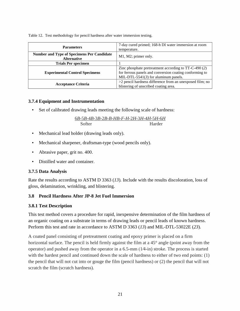
Table 12. Test methodology for pencil hardness after water immersion testing.
Parameters 7-day cured primed; 168-h DI water immersion at room
temperature.
Number and Type of Specimens Per Candidate
Alternative M1, M2; primer only.
Trials Per specimen 1
Experimental Control Specimens
Zinc phosphate pretreatment according to TT-C-490 (2)
for ferrous panels and conversion coating conforming to
MIL-DTL-5541(3) for aluminum panels.
Acceptance Criteria >2 pencil hardness difference from an unexposed film; no
blistering of unscribed coating area.
3.7.4 Equipment and Instrumentation
• Set of calibrated drawing leads meeting the following scale of hardness:
6B-5B-4B-3B-2B-B-HB-F-H-2H-3H-4H-5H-6H
Softer Harder
• Mechanical lead holder (drawing leads only).
• Mechanical sharpener, draftsman-type (wood pencils only).
• Abrasive paper, grit no. 400.
• Distilled water and container.
3.7.5 Data Analysis
Rate the results according to ASTM D 3363 (13). Include with the results discoloration, loss of
gloss, delamination, wrinkling, and blistering.
3.8 Pencil Hardness After JP-8 Jet Fuel Immersion
3.8.1 Test Description
This test method covers a procedure for rapid, inexpensive determination of the film hardness of
an organic coating on a substrate in terms of drawing leads or pencil leads of known hardness.
Perform this test and rate in accordance to ASTM D 3363 (13) and MIL-DTL-53022E (23).
A coated panel consisting of pretreatment coating and epoxy primer is placed on a firm
horizontal surface. The pencil is held firmly against the film at a 45° angle (point away from the
operator) and pushed away from the operator in a 6.5-mm (1⁄4-in) stroke. The process is started
with the hardest pencil and continued down the scale of hardness to either of two end points: (1)
the pencil that will not cut into or gouge the film (pencil hardness) or (2) the pencil that will not
scratch the film (scratch hardness).

22
A film of primer, immersed in JP-8 jet fuel for 168 h or 7 days, shall show no blistering or
wrinkling and no more than a slight yellow to beige color change on submerged area of panel.
Upon removal from the fluid, slight softening is acceptable. After 2 h air-drying, the panel that
was immersed shall be almost indistinguishable with regard to hardness, adhesion, color, and
gloss from a panel prepared at the same time but not immersed. Film softening shall not exceed a
no. 2 pencil hardness difference (see ASTM D 3363) (13) from an unexposed film with identical
cure history prior to hydrocarbon fluid exposure.
3.8.2 Rationale
This test was identified as a performance requirement for designated epoxy primers when
applied over the required conversion pretreatment coatings. Loss of paint adhesion is the primary
failure mode on aluminum and steel.
3.8.3 Test Methodology
The test methodology for pencil hardness after JP-8 immersion is given in table 13.
Table 13. Test methodology for pencil hardness after JP-8 immersion.
Parameters Cured pretreated and primed panels; 168-h JP-8
immersion at room temperature.
Number and Type of Specimens Per Candidate
Alternative M1, M2; primer only.
Trials Per Specimen 1
Experimental Control Specimens
Zinc phosphate pretreatment according to TT-C-490
(2) for ferrous panels and conversion coating
conforming to MIL-DTL-5541(3) for aluminum
panels.
Acceptance Criteria >2 pencil hardness difference from an unexposed film.
3.8.4 Equipment and Instrumentation
• Set of calibrated drawing leads meeting the following scale of hardness:
6B-5B-4B-3B-2B-B-HB-F-H-2H-3H-4H-5H-6H
Softer Harder
• Mechanical lead holder (drawing leads only).
• Mechanical sharpener, draftsman-type (wood pencils only).
• Abrasive paper, grit no. 400.
• JP-8 and container.
3.8.5 Data Analysis
Rate the results according to ASTM D 3363 (13). Include with the results discoloration, loss of
gloss, delamination, wrinkling, and blistering.

23
3.9 Stress Corrosion Cracking
3.9.1 Test Description
Hydrogen embrittlement testing shall be performed on any candidate that is considered a risk
candidate. Resistance to environmentally assisted cracking shall be assessed using the rising step
load method for determination of KIEAC. For this procedure, CV2 Charpy specimens of MIL-A-
46100D (29) shall be machined in longitudinal-transverse (L-T) and transverse-longitudinal
(T-L) orientations in accordance with ASTM E 399-97 (15). Unlike the steel test panels, the
charpy specimens shall not be abrasive blasted prior to pretreatment.
Specimen fatigue precracking shall be carried out using three stages, each consisting of
decreasing loading levels. In the first precracking stage, the load shall be maintained to keep
stress intensity values below 80% of the estimated experimental critical stress intensity and the
stress ratio (max/σmin) kept between –1 and +0.1. In the intermediate stage, the cycling load shall
be reduced to maintain the stress intensity value as crack growth occurs and the intact cross
section reduced. For the final stage of precracking, the load shall be further reduced so the final
value of Kmax will unlikely exceed 60% of the estimated value for KI during experimentation.
Additionally, the final value for Kmax/E should not exceed 0.0032 m1/2, where E is Young’s
modulus. Precrack length, represented by the dimensionless expression a/W (crack length over
specimen width), shall be maintained near 0.5.
Specimens shall be fastened into a double cantilever array test fixture under aqueous conditions
with 3.5% NaCl solution at open circuit potential conditions. Specimens shall be loaded by
incremental steps in accordance with ASTM F 1624-95 (30) using an appropriate load frame
apparatus. The specimen load values versus time shall be recorded. The calculation for the onset
of environmentally assisted cracking, or KIEAC, is derived as follows for cantilever bending from
the four-point bending expression.
(1)
3.9.2 Rationale
The calculation of stress corrosion cracking (hydrogen embrittlement) is necessary for assurance
that this pretreatment can be applied to ferrous substrates with Rockwell hardness greater than
39.
3.9.3 Test Methodology
The test methodology for stress corrosion cracking testing is given in table 14.

24
Table 14. Test methodology for stress corrosion cracking testing.
Parameters CV2 Charpy specimens of MIL-A-46100D (29).
Number and Type of Specimens Per Candidate
Alternative Pretreatment only on coupons for stress-cracking testing.
Trials Per Specimen 1
Experimental Control Specimens Zinc phosphate pretreatment according to TT-C-490 (2)
for ferrous substrates.
Acceptance Criteria Results equal to or lower than baseline zinc phosphate.
3.9.4 Equipment and Instrumentation
The equipment shall be determined by the applicable test method.
3.9.5 Data Analysis
Report results of the stress relief cracking as compared to the baseline zinc phosphate
pretreatment.
3.10 Marine Environment Outdoor Exposure.
3.10.1 Test Description
This test method evaluates a coating system’s (pretreatment/primer/topcoat) ability to prevent
substrate corrosion. Outdoor exposure testing will be conducted at the Cape Canaveral Air Force
Station (CCAFS) Corrosion Test Site, located 100 yards from and faces the Atlantic Ocean. Test
coupons are installed on either wooden or corrosion-resistant metal racks using plastic insulator
stand-offs with stainless steel fasteners. The rack angle of the coupons is 30 from horizontal.
Figure 2 shows an example of the type of exposure racks that will be used.
Figure 2. CCAFS exposure rack.
25
Prepare at least five specimens consisting of manufactured parts that accurately simulate current
production material and manufacturing processes, incorporating the candidate zirconium oxide
pretreatment, and five specimens incorporating the current corrosion protection system. If
manufactured parts are not available, panels shall be prepared from the same representative
metallic substrates and processed under the same manufacturing process.
Scribe an X incision through the coating and to the substrate so that the smaller angle of the X is
30°–45 as described in ASTM D 3359 (9). The scribe should cross the entire length of the panel
but ending 1 in from the edges. The edges and back of the panel are properly coated with the
same coating system as the one being tested. Test samples are stamped or engraved with an
identifying marking under the coating on their backs on the top left corner within a 1/2-in margin
from either edge.
Evaluate coupons for surface corrosion (blisters in field) and creep from scribe as per ASTM D
1654 (5) at 6-month intervals for 2 years. At each inspection interval, remove and visually
examine the coupons using a measuring magnifier device. Corrosive salts or oxides from the
scribes running down the surface of the coupon are ignored in these measurements. The
inspection is more concerned with perforation of the film than staining. Photos are taken of test
coupons at each inspection interval. Upon completion of testing, test coupons are transported to
ARL at Aberdeen Proving Ground, MD, for scanning. After being scanned, each panel is scraped
as described in TT-C-490 (2), rerated using ASTM D1654 (5), and scanned a final time.
3.10.2 Rationale
The 24-month outdoor exposure of scribed, painted substrates is a key accelerated test to
determine overall corrosion inhibition and paint adhesion compared to controls.
3.10.3 Test Methodology
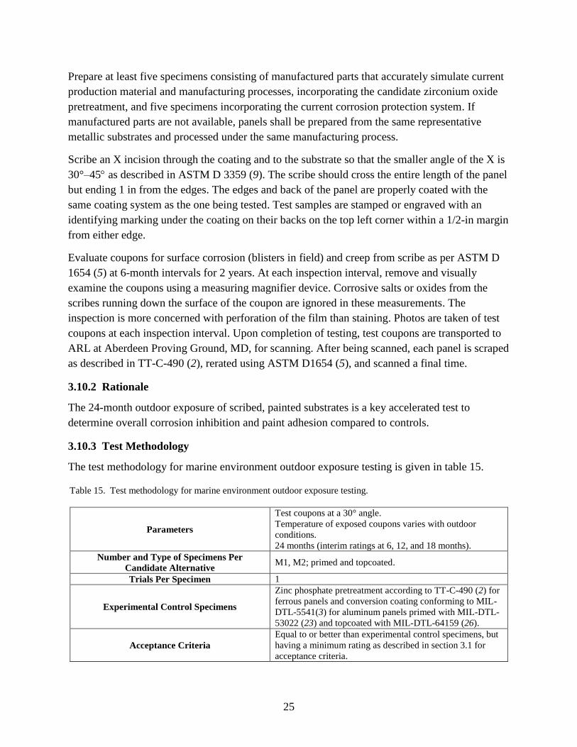
The test methodology for marine environment outdoor exposure testing is given in table 15.
Table 15. Test methodology for marine environment outdoor exposure testing.
Parameters
Test coupons at a 30° angle.
Temperature of exposed coupons varies with outdoor
conditions.
24 months (interim ratings at 6, 12, and 18 months).
Number and Type of Specimens Per
Candidate Alternative M1, M2; primed and topcoated.
Trials Per Specimen 1
Experimental Control Specimens
Zinc phosphate pretreatment according to TT-C-490 (2) for
ferrous panels and conversion coating conforming to MIL-
DTL-5541(3) for aluminum panels primed with MIL-DTL-
53022 (23) and topcoated with MIL-DTL-64159 (26).
Acceptance Criteria
Equal to or better than experimental control specimens, but
having a minimum rating as described in section 3.1 for
acceptance criteria.

26
3.10.4 Equipment and Instrumentation
• Standard racks: see section 5 of ASTM G 50 (20).
• Scribe tool: carbide tip scribe as per ASTM D 1654 (5).
• Straight edge: any straight edge of sufficient length to guide the scribing tool in a straight
line.
3.10.5 Data Analysis
Report the final corrosion test results and 6-month visual observations. Panels are rated
according to ASTM D 1654 (5).
3.11 Field Exposure, On-Vehicle (ASTM D 1654) (5)
3.11.1 Test Description
This test method describes a basic procedure for conducting on-vehicle testing of candidates.
This may be performed by selective replacement or refinishing of an appropriate representative
substrate/component on a vehicle incorporating the candidate or by the use of test specimens
incorporating the candidate attached to the military ground vehicle. This method describes a
procedure for monitoring a coating system’s (surface treatment/primer/topcoat) performance
when applied to specific target areas of an operational platform as compared to the baseline
system. The pretreatment and coating system’s ability to maintain adhesion to the substrate after
exposure to field conditions and to prevent corrosion will be analyzed.
At a minimum, the process shall be conducted to replace or refinish a part or section of the
vehicle in accordance with the suggested finishing parameters and the controls established by the
CARC applications specification MIL-DTL-53072 (1). If using test panels, they shall be
prepared in accordance with ASTM G 50 (20) for static field testing and evaluated using ASTM
D 1654 (5). Identify target components of the platform (this will depend on agreements among
programs, depot, or logistics center personnel, manufacturers, and the principal investigator) that
will observe a significant amount of operational exposure to the environment, representative of
the demonstration site. Representative substrates/components will be pretreated in accordance
with pretreatment manufacturers recommended specifications finishing parameters and controls
established in MIL-DTL-53072 (1).
Components substrates will be evaluated during periodic inspections by visual comparison with
the base vehicle or control samples attached to the vehicle. Inspection of the demonstration
platform or target areas of the demonstration platform shall be at approximate intervals of 3
months, 6 months, 1 year, and 2 years. The Society for Protective Coatings SSPC-VIS-2 (31)
shall be used for evaluating component substrates and control samples. The success criteria for
field testing will be performance greater than or equal to the base vehicle (baseline) or control
sample.

27
3.11.2 Rationale
Pretreatment coatings must perform successfully in the field before they are transitioned to the
end users via revisions of technical manuals, military specifications, and qualified products
databases.
3.11.3 Test Methodology
The test methodology for field exposure testing is given in table 16.
Table 16. Test methodology for field exposure testing.
Parameters Ferrous or mixed substrate components.
Number and Type of Specimens Per Candidate
Alternative
Number of platforms required is determined by cognizant
authority.
Trials Per Specimen 1
Experimental Control Specimens GSE components coated with standard coating system.
Acceptance Criteria
≥2-year operational service or other user-defined interval,
with a minimum of comparable performance with similar
platform coated with standard system.
3.11.4 Equipment and Instrumentation
Military ground vehicle: vehicle used for standard deployment.
3.11.5 Data Analysis
After a predetermined exposure agreed upon by the stakeholders, the affected vehicles/parts shall
be evaluated for coating adhesion, color, and corrosion resistance in accordance with SSPC-VIS-
2 (31), MIL-DTL-53072 (1), and ASTM D 1654 (5).

28
4. References
1. MIL-DTL-53072. Chemical Agent Resistant Coating (CARC) Systems Application
Procedures and Quality Control 2013.
2. TT-C-490. Chemical Conversion Coatings and Pretreatments for Metallic Substrates (Base
for Organic Coatings) 2013.
3. MIL-DTL-5541. Chemical Conversion Coatings on Aluminum and Aluminum Alloys 2006.
4. ASTM B 117. Standard Practice for Operating Salt Spray (Fog) Apparatus. Annu. Book
ASTM Stand. 2011.
5. ASTM D 1654. Standard Test Method for Evaluation of Painted or Coated Specimens
Subjected to Corrosive Environments. Annu. Book ASTM Stand. 2008.
6. ASTM D 714. Standard Test Method for Evaluating Degree of Blisters of Paint. Annu. Book
ASTM Stand. 2009.
7. GMW 14872. Cyclic Corrosion Laboratory Test; General Motors Company, 2010.
8. ASTM G 1. Standard Practice for Preparing, Cleaning and Evaluation of Corrosion Test
Specimens. Annu. Book ASTM Stand. 2011.
9. ASTM D 3359. Standard Test Method for Measuring Adhesion by Tape Test. Annu. Book
ASTM Stand. 2010.
10. ASTM D 4541. Standard Test Method for Pull-Off Strength of Coatings Using Portable
Adhesion Testers. Annu. Book ASTM Stand. 2010.
11. ASTM D 522. Standard Test Method for Mandrel Bend Test of Attached Organic Coatings.
Annu. Book ASTM Stand. 2008.
12. FED-STD-141. Paint, Varnish Lacquer and Related Materials, Methods of Inspection,
Sampling and Testing 2001.
13. ASTM D 3363. Standard Test Method for Film Hardness by Pencil Test. Annu. Book ASTM
Stand. 2012.
14. ASTM D 1308. Standard Test Method for Effect of Household Chemicals on Clear and
Pigmented Organic Finishes. Annu. Book ASTM Stand. 2013.
15. ASTM E 399. Standard Test Method for Plane-Strain Fracture Toughness of Metallic
Materials. Annu. Book ASTM Stand. 2013.
29
16. ASTM G 30. Standard Practice for Making and Using U-Bend Stress-Corrosion Test
Specimens. Annu. Book ASTM Stand. 2009.
17. ASTM G 38. Standard Practice for Making and Using C-Ring Stress-Corrosion Specimens.
Annu. Book ASTM Stand.2013.
18. ASTM G 39. Standard Practice for Preparation and Use of Bent-Beam-Stress-Corrosion Test
Specimens. Annu. Book ASTM Stand. 2011.
19. ASTM G 47. Standard Test Method for Determining Susceptibility to Stress Corrosion
Cracking of 2XXXand 7XXX Aluminum Alloy Products. Annu. Book ASTM Stand. 2011.
20. ASTM G 50. Standard Practice for Conducting Atmospheric Corrosion Tests on Metals.
Annu. Book ASTM Stand. 2010.
21. MIL-DTL-53039. Coating, Aliphatic Polyurethane, Single Component, Chemical Agent
Resistant 2013.
22. ASTM F 22-13. Standard Test Method for Hydrophobic Surface Films by the Water Break
Test. Annu. Book ASTM Stand. 2013.
23. MIL-DTL-53022. Primer, Epoxy Coating, Corrosion Inhibiting, Lead and Chromate Free
2012.
24. MIL-DTL-53030. Primer Coating, Epoxy, Water Base, Lead and Chromate Free 2011.
25. MIL-PRF-32348. Powder Coating, Camouflage Chemical Agent Resistant Systems 2013.
26. MIL-DTL-64159. Camouflage Coating, Water Dispersible Aliphatic Polyurethane, Chemical
Agent Resistant 2011.
27. ANSI B 94.50. Basic Nomenclature and Definitions for Single Point Cutting Tools 1975.
28. GM 4465P. Water Fog Humidity Test; General Motors Company, 1995.
29. MIL-A-46100. Armor Plate, Steel, Wrought, High-Hardness 2008.
30. ASTM F 1624. Standard Test Method for Measurement of Hydrogen Embrittlement
Threshold in Steel by the Incremental Step Loading Technique. Annu. Book ASTM Stand.
2012.
31. SSPC-VIS-2. Standard Method of Evaluating degree of Rusting on Painted Steel Surfaces;
The Society for Protective Coatings, 2008.

30
INTENTIONALLY LEFT BLANK
31
Appendix. Participating Organizations and Representatives

32
Organization Representative Type
Army Research Laboratory Fred Lafferman (410) 306-1520 Government
Army Aviation and Missile Command Mark Feathers (256) 842-7355 Government
Army Tank and Automotive Command Daniel Nymberg (586) 282-7445 Government
Naval Surface Warfare Center,
Carderock Division Andrew Sheetz (301) 227-5037 Government
Letterkenny Army Depot Dennis Reed (717) 267-8376 Government
Marine Corps Logistics Base Albany Steve Allen (229) 639-5310 Government
Army Research Laboratory John Escarsega (410) 306-0693 Government
PPG Industries Larry Fitzgerald (412) 492-5396 Contractor
PPG Industries Jonathan Love (412) 492-5206 Contractor

33
List of Symbols, Abbreviations, and Acronyms
ANSI American National Standards Institute
ARL U.S. Army Research Laboratory
ASTM American Society for Testing and Materials
BP best performance
CARC chemical agent–resistant coating
cfm cubic feet per minute
CPAC Corrosion Prevention and Control
Cr6+
hexavalent chromium
DOD Department of Defense
EAC environmentally assisted cracking
ESTCP Environmental Security Technology Certification Program
FZA fluorozirconic acid
GMW General Motors Worldwide
GSE ground support equipment
HazMat hazardous material
HHA high-hard armor
IP improved performance
JTP joint test protocol
JTR joint test report
MMC metal-matrix composite
MP minimum performance
Ni nickel
NSS neutral salt spray
OEM original equipment manufacturer

34
pH hydrogen ion concentration
SSPC The Society of Protective Coatings
TACOM U.S. Army Tank Automotive Command

NO. OF
COPIES ORGANIZATION
35
1 DEFENSE TECHNICAL
(PDF) INFORMATION CTR
DTIC OCA
1 DIRECTOR
(PDF) US ARMY RESEARCH LAB
IMAL HRA
1 DIRECTOR
(PDF) US ARMY RESEARCH LAB
RDRL CIO LL
1 GOVT PRINTG OFC
(PDF) A MALHOTRA
1 DIRECTOR
(PDF) US ARMY RESEARCH LAB
RDRL WMM C
F LAFFERMAN

36
INTENTIONALLY LEFT BLANK.