joint parameter estimation of serial ... int. j. mech. eng. & rob. res. 2014 k n v swamy and a...
TRANSCRIPT

725
Int. J. Mech. Eng. & Rob. Res. 2014 K N V Swamy and A Gopi Chand, 2014
JOINT PARAMETER ESTIMATION OF SERIALMANIPULATORS USING RIGID BODY DYNAMICS
K N V Swamy1* and A Gopi Chand2
*Corresponding Author: K N V Swamy,[email protected]
Use of Robotic manipulators is wide spread in Mechanical Industries. Serial Manipulators takethe major share in this aspect. Rigid Body dynamics is an efficient tool for estimating effect ofinertial loads on joint torques and thus help in generating a better control system for roboticmanipulators. In the current work, the use of Rigid Body Dynamics using the motion analysispackage in commercial software (Solidworks) is used. The results are verified analytically. RigidBody Dynamic Analysis are also performed on 3DOF planar manipulator and 3DOF spatialmanipulator. The results of simulations of 3DOF spatial manipulators are taken as input forstress analysis using FEA.
Keywords: Rigid body dynamics, Motion analysis, Planar manipulator, Joint torque
INTRODUCTIONRobotic manipulators are widely being usedfor material handling and other applications inindustry. The manipulators used for thispurpose can be widely classified into twocategories: 1) Serial manipulators, and 2)ParallelManipulators. Parallel manipulators,due to their robust structure, have good loadbearing capacity while because of the samestructure have a very low work volume. SerialManipulators on the other have good dexterityand greater work volume but lesser strengthdue to their open chain structure. Thus it isalways necessary to understand the forces andtorques that are acting at various joints. Rigid
ISSN 2278 – 0149 www.ijmerr.comVol. 3, No. 4, October 2014
© 2014 IJMERR. All Rights Reserved
Int. J. Mech. Eng. & Rob. Res. 2014
1 M.Tech Student, Department of Mechanical Engineering, Swarnandhra College of Engineering and Technology, Narsapur, AP, India.2 Professor and HOD, Department of Mechanical Engineering, Swarnandhra College of Engineering and Technology, Narsapur, AP,
India.
Body Dynamics proves to be a promisingsolution in this regard. Rigid Body Dynamicsinvolves the study of forces and reactions thatare arising due to interaction of various bodies.During this analysis, the bodies areconsidered as non-deformable rigid bodies.This involves both kinematic and kineticsimulation of bodies. Many researchers haveused this procedure for studying the behaviorof manipulators and synthesizing themanipulator.
Vishal Abhishek et al. (2014) used RigidBody Dynamics to estimate the dynamicparameters of an industrial robot KUKA KR5.Euler-Lagrangian formulation is used for this
Research Paper

726
Int. J. Mech. Eng. & Rob. Res. 2014 K N V Swamy and A Gopi Chand, 2014
purpose. Then the equations of motionobtained were linearized and expressed interms of the base parameters. The numericalvalues of base parameters were obtained bylinear regression technique applied to thepoints along a given planar trajectory. Theobtained values are verified experimentally.Shankar and Vamsi Krishna (2014)demonstrated the use of Rigid Body Dynamicsfor computing workspace of a parallelmanipulator. Creo 2.0 MDX module is usedfor this purpose. Takamitsu Matsubara et al.(2014) estimated inertial parameters usingrigid body dynamics for modal based controlof serial manipulator. The approach is focusedon task specif ic subspace. A modernstatistical supervised learning frameworkcalled covariate shift adaptation equipped witha direct importance estimation method forestimating inertial parameters is alsoproposed by them. Amit et al. (2014) did arigid body simulation to obtain the interactingforces of various members in a wipermechanism and then transferred these forcesto FEA models for performing stress analysis.Sanjeev Soni et al. (2013) used ADAMS toperform kinematic analysis for computingworkspace of a 3DOF medical manipulator.The obtained results are verified using D-Hparameters. Patel and Gorge (2013) usedkinematic analysis for workspacecomputation. Ling Wen et al. (2013)discussed the use of 5 DOF serial manipulatorfor various applications investigated. Varioustechniques for rigid body dynamics of themanipulator discussed. The 3D model of themanipulator is generated in Solidworks.Kurfess (2005) and Niku (2013) gave a lot offormulations for computing joint parameters for
various types of manipulators with variouscases. Ana Djuric et al. (2012) developed n-GDM, a generalized dynamic modelcomputation system to compute the joint torquecharacteristics. This is based on n-GKMkinematic model that was developed by thesame authors which can automaticallygenerate the kinematic model based on thetype of joints given as input. The model thatwas developed used MAPLE 12.0 mathsymbolic language. Burak Baykus et al. (2011)used rigid body dynamics to compute theinteraction forces for designing a luggagedoor. Ngoc Dung Vuong and Marcelo Ang(2009) proposed a dynamic modelconsidering the dynamic effects of friction whencomputing joint parameters. The highly non-linear nature of friction is compensated usinga static friction model. Wisama Khalil et al.(2007) presented four methods for calculatingthe inertia effects of load on the jointparameters. Theingi et al. (2002) discussedthe formulations for kinematics of a 2DOFplanar manipulator formed by using a 5-barchain. Saha (1999) discussed the constraineddynamic equations of motion of serialmultibody systems consisting of rigid bodiesin a serial kinematic chain. Quanzhao et al.(2011) performed a kinematic simulation of a2DOF parallel manipulator using Matlab.
Most of the above researchers tooksymbolic models instead of accurate 3Dmodels to compute the inertia effects in serialmanipulators. Many of the current high endcommercial modeling software are nowproviding the facility of Rigid Body Dynamics.In the current work an attempt has been madeto use a commercial software (Solidworks) togenerate the 3D models and perform Rigid
727
Int. J. Mech. Eng. & Rob. Res. 2014 K N V Swamy and A Gopi Chand, 2014
Body Dynamic Analysis. The results obtainedin case of a 2DOF planar manipulator arecompared with that of theoretical calculations.
PROBLEM STATEMENTAs mentioned in the previous section, the aimthe current work is to demonstrate the use ofcommercially available modeling software togenerate 3D models as well as to perform rigidbody dynamic analysis. The obtained jointparameters are then transferred to FE moduleof the same software and FE analysis isperformed on the manipulators. Three differentmanipulators are considered during the study.They are:
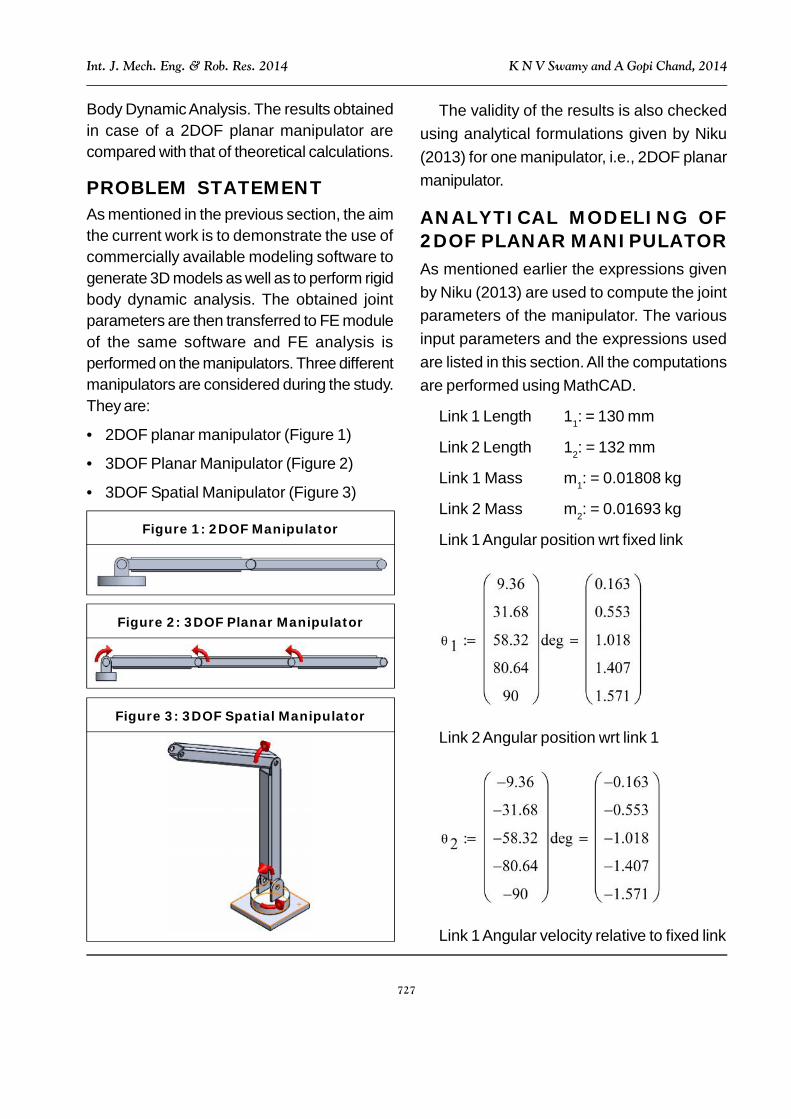
• 2DOF planar manipulator (Figure 1)
• 3DOF Planar Manipulator (Figure 2)
• 3DOF Spatial Manipulator (Figure 3)
The validity of the results is also checkedusing analytical formulations given by Niku(2013) for one manipulator, i.e., 2DOF planarmanipulator.
ANALYTICAL MODELING OF2DOF PLANAR MANIPULATORAs mentioned earlier the expressions givenby Niku (2013) are used to compute the jointparameters of the manipulator. The variousinput parameters and the expressions usedare listed in this section. All the computationsare performed using MathCAD.
Link 1 Length 11: = 130 mm
Link 2 Length 12: = 132 mm
Link 1 Mass m1: = 0.01808 kg
Link 2 Mass m2: = 0.01693 kg
Link 1 Angular position wrt fixed link
1
9.36
31.68
58.32
80.64
90
deg
0.163
0.553
1.018
1.407
1.571
Link 2 Angular position wrt link 1
2
9.36
31.68
58.32
80.64
90
deg
0.163
0.553
1.018
1.407
1.571
Link 1 Angular velocity relative to fixed link
Figure 1: 2DOF Manipulator
Figure 2: 3DOF Planar Manipulator
Figure 3: 3DOF Spatial Manipulator

728
Int. J. Mech. Eng. & Rob. Res. 2014 K N V Swamy and A Gopi Chand, 2014
Link 2 Angular velocity relative to link 1
2
17.28
25.9151
25.9265
17.3284
0.107
deg
s
0.302
0.452
0.453
0.302
1.868 103
1
s
Link 1 Angular Acceleration
1
12.959999999967
4.33954069600863
4.29372185015424
12.8952639685857
21.5136000001924
deg
sec2
0.226
0.076
0.075
0.225
0.375
1
s2
Link 2 Angular Acceleration
2
12.959999999967
4.33954069600863
4.29372185015424
12.8952639685857
21.5136000001924
deg
sec2
0.226
0.076
0.075
0.225
0.375
1
s2
Torque at Joint 1
T 11
3m 1 l1
2 m 2 l12
1
3m 2 l2
2 m 2 l1 l2 C 2
1
1
3m 2 l2
21
2m 2 l1 l2 C 2
2 m 2 l1 l2 S 2 1 2
1
2m 2 l1 l2 S 2 2
2
1
2m 1 m 2
g l1 C 11
2m 2 g l2 C 12
0.043
0.039
0.028
0.016
0.011
J
T 11
3m 1 l1
2 m 2 l12
1
3m 2 l2
2 m 2 l1 l2 C 2
1
1
3m 2 l2
21
2m 2 l1 l2 C 2
2 m 2 l1 l2 S 2 1 2
1
2m 2 l1 l2 S 2 2
2
1
2m 1 m 2
g l1 C 11
2m 2 g l2 C 12
0.043
0.039
0.028
0.016
0.011
J
T11
3m1 l1
2 m2 l12
1
3m2 l2
2 m2 l1 l2 C2
1
1
3m2 l2
21
2m2 l1 l2 C2
2 m2 l1 l2 S2 1 2
1
2m2 l1 l2 S2 2
2
1
2m1 m2
g l1 C11
2m2 g l2 C12
0.043
0.039
0.028
0.016
0.011
J
T11
3m1 l1
2 m2 l12
1
3m2 l2
2 m2 l1 l2 C2
1
1
3m2 l2
21
2m2 l1 l2 C2
2 m2 l1 l2 S2 1 2
1
2m2 l1 l2 S2 2
2
1
2m1 m2
g l1 C11
2m2 g l2 C12
0.043
0.039
0.028
0.016
0.011
J
Torque at Joint 2
T21
3m2 l2
21
2m2 l1 l2 C2
1
1
3m2 l2
2 21
2m2 l1 l2 S2 1
21
2m2 g l2 C12
0.011
0.011
0.011
0.011
0.011
J
T21
3m2 l2
21
2m2 l1 l2 C2
1
1
3m2 l2
2 21
2m2 l1 l2 S2 1
21
2m2 g l2 C12
0.011
0.011
0.011
0.011
0.011
J
SIMULATION RESULTSAs mention earlier, rigid body dynamicsimulation is carried out on variousmanipulators. This section presents thesimulation results on all manipulatorsconsidered.
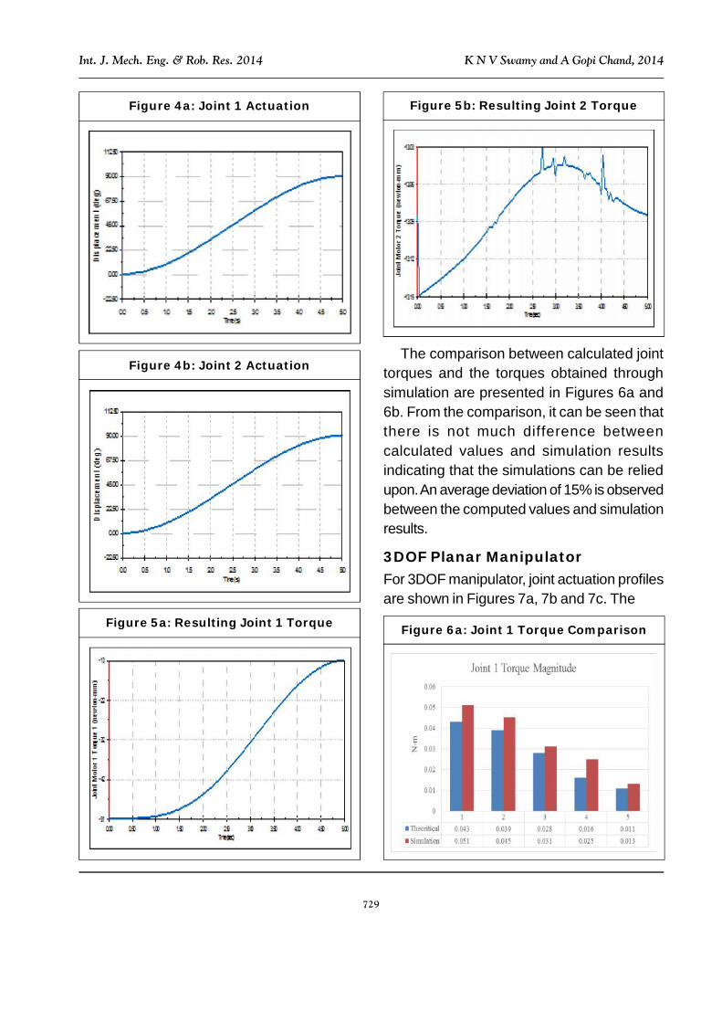
2DOF Planar ManipulatorFigure 1 gives the 2DOF manipulatorconsidered for analysis. In all the three casesthe corresponding link lengths are the same.The cross section of Link 1 and Link 3 in allthe cases is a box of 15 mm x 15 mm x 1 mmthick while link 2 has a cross section of 13 mmx 13 mm x 1 mm. The solid models are createdin Solidworks. Joint actuation motors areapplied and actuation is performed. Jointactuation profiles for 2 DOF manipulator areshown in Figures 4a and 4b. Gravity is enabledin all cases. The torques computed byexecuting the Rigid Body Dynamic analysisare given in Figures 5a and 5b.
729
Int. J. Mech. Eng. & Rob. Res. 2014 K N V Swamy and A Gopi Chand, 2014
Figure 4a: Joint 1 Actuation
Figure 4b: Joint 2 Actuation
Figure 5a: Resulting Joint 1 Torque
Figure 5b: Resulting Joint 2 Torque
The comparison between calculated jointtorques and the torques obtained throughsimulation are presented in Figures 6a and6b. From the comparison, it can be seen thatthere is not much difference betweencalculated values and simulation resultsindicating that the simulations can be reliedupon. An average deviation of 15% is observedbetween the computed values and simulationresults.
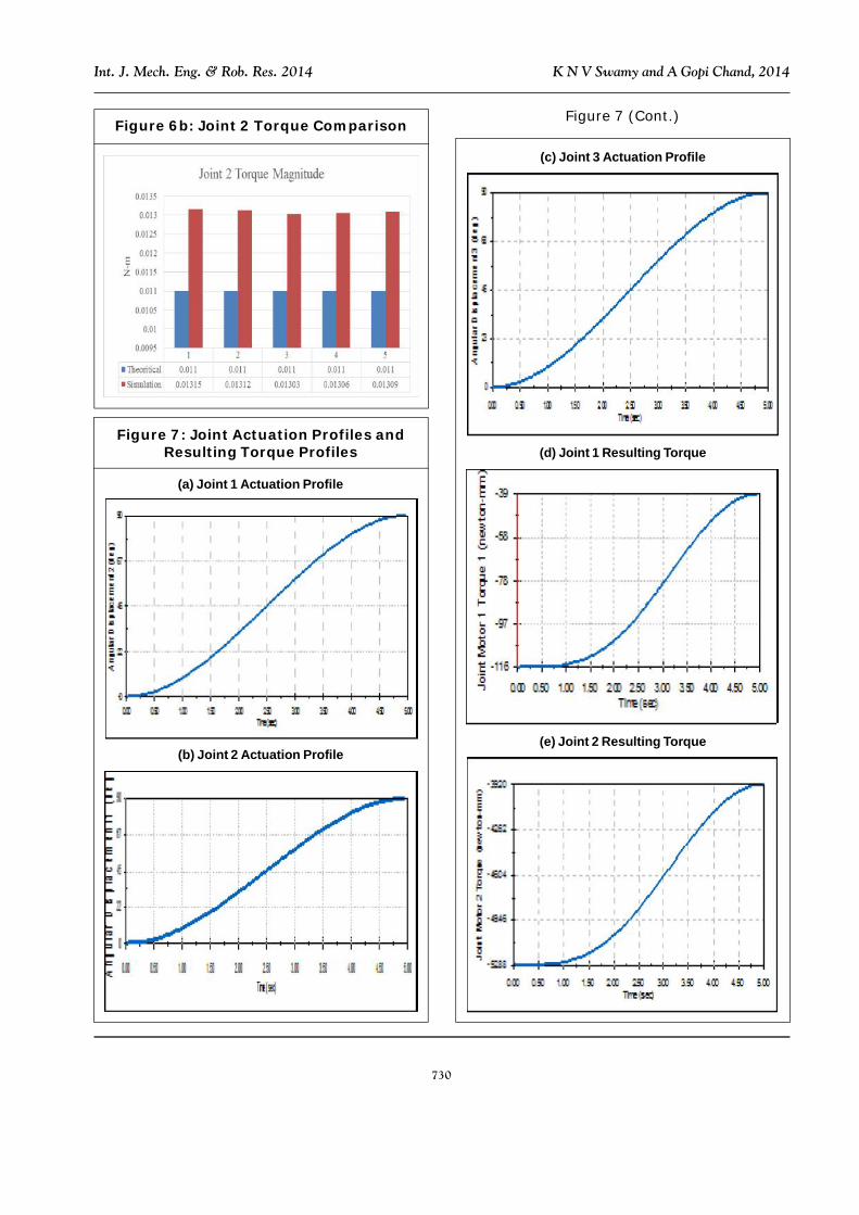
3DOF Planar ManipulatorFor 3DOF manipulator, joint actuation profilesare shown in Figures 7a, 7b and 7c. The
Figure 6a: Joint 1 Torque Comparison
730
Int. J. Mech. Eng. & Rob. Res. 2014 K N V Swamy and A Gopi Chand, 2014
Figure 6b: Joint 2 Torque Comparison
Figure 7: Joint Actuation Profiles andResulting Torque Profiles
(b) Joint 2 Actuation Profile
(a) Joint 1 Actuation Profile
Figure 7 (Cont.)
(d) Joint 1 Resulting Torque
(e) Joint 2 Resulting Torque
(c) Joint 3 Actuation Profile

731
Int. J. Mech. Eng. & Rob. Res. 2014 K N V Swamy and A Gopi Chand, 2014
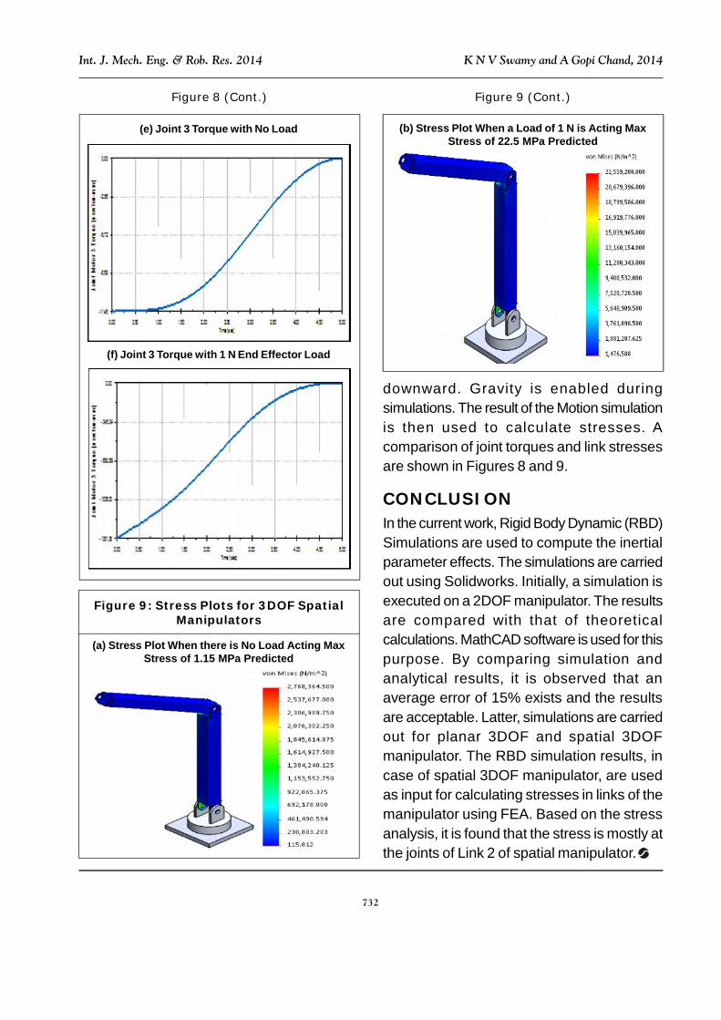
3DOF Spatial ManipulatorThe configuration of this manipulator is shownin Figure 3. For this, Joints 1 and 2 areactuated through 90° for 5 sec in CW and CCWdirections respectively while the joint 3 isactuated through a distance of 60° for 5 sec inCW direction. Two cases are consideredduring simulation: (i) without any end effectorload, (ii) with end effector load. The end effectorload is considered as 1 N acting vertically
Figure 7 (Cont.)
(f) Joint 3 Resulting Torque
Figure 8: Joint Torque Estimationfor 3DOF Spatial Manipulator in No Load
and Loaded Condition
(a) Joint 1 Torque with No Load
Figure 8 (Cont.)
(c) Joint 2 Torque with No Load
(d) Joint 2 Torque with 1 N End Effector Load
(b) Joint 1 Torque with 1 N End Effector Load
732
Int. J. Mech. Eng. & Rob. Res. 2014 K N V Swamy and A Gopi Chand, 2014
Figure 8 (Cont.)
(e) Joint 3 Torque with No Load
(f) Joint 3 Torque with 1 N End Effector Load
Figure 9 (Cont.)
(b) Stress Plot When a Load of 1 N is Acting MaxStress of 22.5 MPa Predicted
Figure 9: Stress Plots for 3DOF SpatialManipulators
(a) Stress Plot When there is No Load Acting MaxStress of 1.15 MPa Predicted
downward. Gravity is enabled duringsimulations. The result of the Motion simulationis then used to calculate stresses. Acomparison of joint torques and link stressesare shown in Figures 8 and 9.
CONCLUSIONIn the current work, Rigid Body Dynamic (RBD)Simulations are used to compute the inertialparameter effects. The simulations are carriedout using Solidworks. Initially, a simulation isexecuted on a 2DOF manipulator. The resultsare compared with that of theoreticalcalculations. MathCAD software is used for thispurpose. By comparing simulation andanalytical results, it is observed that anaverage error of 15% exists and the resultsare acceptable. Latter, simulations are carriedout for planar 3DOF and spatial 3DOFmanipulator. The RBD simulation results, incase of spatial 3DOF manipulator, are usedas input for calculating stresses in links of themanipulator using FEA. Based on the stressanalysis, it is found that the stress is mostly atthe joints of Link 2 of spatial manipulator.

733
Int. J. Mech. Eng. & Rob. Res. 2014 K N V Swamy and A Gopi Chand, 2014
REFERENCES1. Amit A Nimbalkar and B E Narkhede
(2014), “FEA Analysis of An ElectricWiper Mechanism”, International Journalfor Scientific Research & Development,Vol. 2, No. 5, pp. 275-278.
2. Ana Djuric, Riyadh Al Saidi and WaguihElMaraghy (2012), “Dynamics Solution ofn-DOF Global Machinery Model”, Roboticsand Computer-Integrated Manufacturing,Vol. 28, No. 5, pp. 621-630.
3. Burak Baykus, Elmas Anli and IbrahimOzkol (2011), “Design and KinematicsAnalysis of a Parallel Mechanism to beUtilized as a Luggage Door by an Analogyto a Four-Bar Mechanism”, Engineering,Vol. 3, No. 4, pp. 411-421.
4. Kurfess T R (2005), “LagrangianDynamics”, Robotics and AutomationHandbook, Chapter 1, pp. 1-18.
5. Ling Wen, Yu Zhang, Lufeng Luo andCong Zhang (2013), “Five Degree ofFreedom Manipulator Motion SimulationBased on Virtual Environment”, ModernMechanical Engineering, Vol. 3, No. 1,pp. 34-38.
6. Ngoc Dung Vuong and Marcelo H Ang Jr.(2009), “Dynamic Model Identification forIndustrial Robots”, Acta PolytechnicaHungarica, Vol. 6, No. 5, pp. 51-68.
7. Patel Y D and George P M (2013),“Kinematic Analysis and 3D WorkspaceDevelopment of 3DOF ParallelManipulator with a Rotary Base”, 1st
International & 16th National Conferenceon Machines and Mechanisms(iNaCoMM 2013), pp. 672-679, IIT,Roorkee.
8. Quanzhao Tu, Xiafu Peng, Jiehua Zhouand Xunyu Zhong (2011), “KinematicsSimulation and Analysis of 2DOF ParallelManipulator with Highly RedundantActuation”, URL: www.scirp.org/journal/paperdownload.aspx? paperid=28000
9. Saeed B Niku (2013), “Dynamic Analysisand Forces”, Chapter 4, pp. 147-177,Industrial Robotics, Wiley Publications.
10. Saha S K (1999), “Dynamics of SerialMultibody Systems Using the DecoupledNatural Orthogonal ComplementMatrices”, Journal of Applied Mechanics,Vol. 66, No. 4, pp. 986-996.
11. Sanjeev Soni, Kuldeep Singh, SanjeevVerma, Dinesh Pankaj and Amod Kumar(2013), “Kinematic and DynamicAnalysis of a Surgical Tool ManipulatorTowards Robotic Surgery”, 1 st
International & 16th National Conferenceon Machines and Mechanisms(iNaCoMM 2013), pp. 987-991, IIT,Roorkee.
12. Shankar N V S and Vamsi Krishna P(2014), “Workspace Computation UsingMotion Analysis”, International Journal ofMechanical Engineering and RoboticsResearch, Vol. 3, No. 1, pp. 198-203.
13. Takamitsu Matsubara, Hiroaki Takada andKenji Sugimoto (2014), “Task-AdaptiveInertial Parameter Estimation of Rigid-Body Dynamics with Modeling Error forModel-Based Control Using CovariateShift Adaptation”, IEEE/ASME InternationalConference on Advanced IntelligentMechatronics (AIM), pp. 476-482.
14. Theingi Chuan Li, I-Ming Chen and JorgeAngeles (2002), “Singularity Management

734
Int. J. Mech. Eng. & Rob. Res. 2014 K N V Swamy and A Gopi Chand, 2014
of 2DOF Planar Manipulator UsingCoupled Kinematics”, 7th InternationalConference on Control, Automation,Robotics & Vision (ICCARV 2002),Singapore.
15. Vishal Abhishek, Abdullah Aamir Hayat,Arun Dayal Udai and Subir Kumar Saha(2014), “Identif ication of DynamicParameters of an Industrial Manipulator”,The 3rd Joint International Conference on
Multibody System Dynamics the 7th AsianConference on Multibody Dynamics,BEXCO, Busan, Korea.
16. Wisama Khalil, Maxime Gautier andPhilippe Lemoine (2007), “Identifcation ofthe Payload Inertial Parameters ofIndustrial Manipulators”, IEEEInternational Conference on Robotics andAutomation - ICRA’07.