jmee.tu.koszalin.pljmee.tu.koszalin.pl/download/jmee_sample_manuscript.docx · web viewso far...
TRANSCRIPT

ISSN: 2544-0780Vol. 1 | No. 1 | 2017 | pp. 1-8
DOI: XXXXXXXXXXXXXXXXX
EFFECT OF MACRO-GEOMETRY OF THE GRINDING WHEEL ACTIVE SURFACE ON TRAVERSE
INTERNAL CYLINDRICAL GRINDING PROCESS
Krzysztof NADOLNY1*, Wojciech KAPŁONEK2, Nicolae UNGUREANU3
1* Faculty of Mechanical Engineering, Department of Production Engineering, Koszalin University of Technology, Raclawicka 15-17, 75-620, Koszalin, Poland, e-mail: [email protected]
2 Faculty of Mechanical Engineering, Department of Production Engineering, Koszalin University of Technology, Poland
3 Department of Engineering and Technological Management, Technical University of Cluj Napoca, North University Center of Baia Mare, Romania
(Received 3 March 2017, Accepted 26 May 2017)
Abstract: This article presents results of experimental tests of internal cylindrical traverse grinding in which the total machining allowance is removed in a single pass. Grinding wheels with zone-diversified structure made on basis of abrasive grains from Al 2O3 were used in the process. Such tools are characterized by different construction of rough and finish grinding zones. Moreover, conic chamfer is shaped on their active surface that allows for even distribution of machining allowance on the grinding wheel surface. What is described in the hereby work is a device for precise shaping of conic chamfer on the grinding wheel active surface (GWAS). The work also presents results of tests whose aim was to determine the influence of grinding wheel macrogeometry on the process of internal cylindrical traverse grinding of internal cylindrical surfaces made from steel 100Cr6. Changes of selected parameters of the machined surface geometric structure (Ra, Rz, RSm, Rdq and RTp) and values of the grinding power P were analyzed. It was proved that the greater the conic chamfer width, the better the results.
Keywords: grinding wheel active surface (GWAS), conic chamfer, internal cylindrical grinding, traverse grinding
1. INTRODUCTION
In modern production processes there is an incessant drive towards increasing the precision of dimensions, shape and quality of the machined workpiece surface and towards limiting the costs through an increase in the machining efficiency and shortening its time. The possibilities of increasing the efficiency of the operation through an increase in the values of machining parameters are, however, limited. This refers mainly to the process of internal cylindrical grinding, where increasing the machining parameter values is limited by the dynamic rigidity of the grinders and the grinding wheels’ resistance.
Therefore, various modifications are sought, that would make it possible to overcome the above limitations. From among many innovative solutions, high hopes are placed in traverse grinding processes in
which the total machining allowance is removed in a single pass of the grinding wheel [1-9]. What seems exceptionally beneficial in this context is grinding with grinding wheels with conic chamfer shaped in their attacking part. It makes it possible to separate the function of rough and finish grinding into two zones. Thanks to the proper shaping of the conic chamfer in relation to the thickness of the machining allowance, a wide zone of rough grinding is obtained with a large number of active grains, which guarantees considerable increase of the grinding efficiency in relation to the reciprocal grinding process.
So far expensive superhard grinding wheels from cubic boron nitride (CBN) were used in such processes, which required specialist grinders with significant rigidity and great grinding speed (vs > 60 m/s) [6]. As the general costs of such

2 Nadolny K., Kapłonek W., Ungureanu N. | Journal of Mechanical and Energy Engineering, Vol. 1, No. 1,2017, pp. 1-8
a process are relatively high, it is expected that new grinding wheel constructions are developed from far cheaper grains that may be successfully used in conventional internal cylindrical grinders.
For this purpose a theoretical and experimental basis of internal cylindrical traverse grinding using zone-diversified structure grinding wheels, made from conventional abrasives on basis of Al2O3 were developed. Such grinding wheels are divided into two functional zones (rough and finish grinding zones), with characteristic and different construction [10-12].
2. DEVICE FOR PRECISION SHAPING MACRO-GEOMETRY OF THE GRINDING WHEEL
Effective realization of the process of internal cylindrical traverse grinding with zone-diversified structure grinding wheels is possible if precise shaping of the used grinding wheel active surface macro-geometry is provided. Both the construction of conventional grinders and CNC allows for changing the angular location of the grinding wheel spindle, thanks to which it is possible to make conic chamfer on the grinding wheel active surface. Such changes in the shaping machine settings are, however, labor-intensive and therefore unprofitable if they need to be performed with each dressing procedure. On top of that they don’t provide sufficient precision of angular positioning.
In order to make it possible to quickly shape the conic chamfer with given geometrical parameters on the GWAS, it was necessary to construct special device. The most important element of that device (Fig. 1) is a sliding table on ball slideways, to which a disk mounting of single-grain diamond dresser and a micrometer screw were mounted. Thanks to the latter, given values of the conic chamfer may be applied with high precision (±3%) [13, 14].
Fig. 1. Device for shaping macrogeometry of the grinding wheel active surface
The device was equipped with a table drive system that consisted of a feeder, drive engine and a toothed bar. The reciprocal and traverse movement was steered
using a contactor and limit switches placed in the extreme positions of the table feed. The complete system was mounted on the top part of the basis in order to maintain unchanged dressing kinematics with different values of the conic chamfer.
3. EXPERIMENTAL INVESTIGATIONS
Using the developed device, tests were carried out whose aim was to determine the most advantageous parameters of the conic chamfer shaped in the dressing cut on the active surface of grinding wheels with zone-diversified structure.
3.1. Methodology of experimental investigationsDuring the realized tests value of the conic
chamfer was adjusted to the size of the working contact ae in such a way so as to make the conic part of the abrasive tool covered the whole machining allowance for the machining. The second parameter to which angle belonged was the chamfer width b. With the same working contact, a change of the chamfer width caused considerable angle differences (Fig. 2), whose values during the tests were = 0.38-1.15.
Fig. 2. The width b and the angle χ of the grinding wheel conic chamfer shaped in experimental investigations
Internal cylindrical surfaces of bearing rings mad from steel 100Cr6 with internal diameter dw = 40 mm were grinded.
Table 1 presents the most important parameters of the realized experimental tests.
During the tests, the initial and maximum grinding power P was registered, while after their termination, general axial machined surface roughness profile was registered on basis of which the following parameters were determined: Ra – arithmetic mean deviation of the assessed
profile; Rz – maximum height of the profile within
a sampling length; RSm – mean width of profile elements, within
a sampling length; Rdq – root-mean-square (RMS) slope of the
profile within a sampling length; RTp – material ratio of the complete profile.

Nadolny K., Kapłonek W., Ungureanu N. | Journal of Mechanical and Energy Engineering, Vol. 1, No. 1, 2017, pp. 1-8 3
Tab. 1. General characteristics of grinding conditions
Process Peripheral internal cylindrical traverse grinding
Grinding machine
Universal grinding machine RUP 28P equipped with spindle type EV-70/70-2WB produced by Fisher AG, Switzerland (max. rpm 60 000 min-1, power of machine cutting 5.2 kW)
Dressing parameters
Dresser: single grain diamond dresserQd = 1.25 kt, nsd = 12 000 rpm,vfd = 10 m/s, aed = 0.0125 mmid =10, = 0.38-1.15°, b = 15-5 mm
Grinding parameters
vs = 60 m/s, vw = 0.6 m/s, vfa = 1.0 mm/s, ae = 0.10 mm, QC = 5.0 l/min
Coolant 5% water solution of CastrolSyntilo RHS oil
WorkpieceInternal cylindrical surface of rings, made of 100Cr6 steel, internal diameter: dw = 40 mm, width: bw = 18 mm
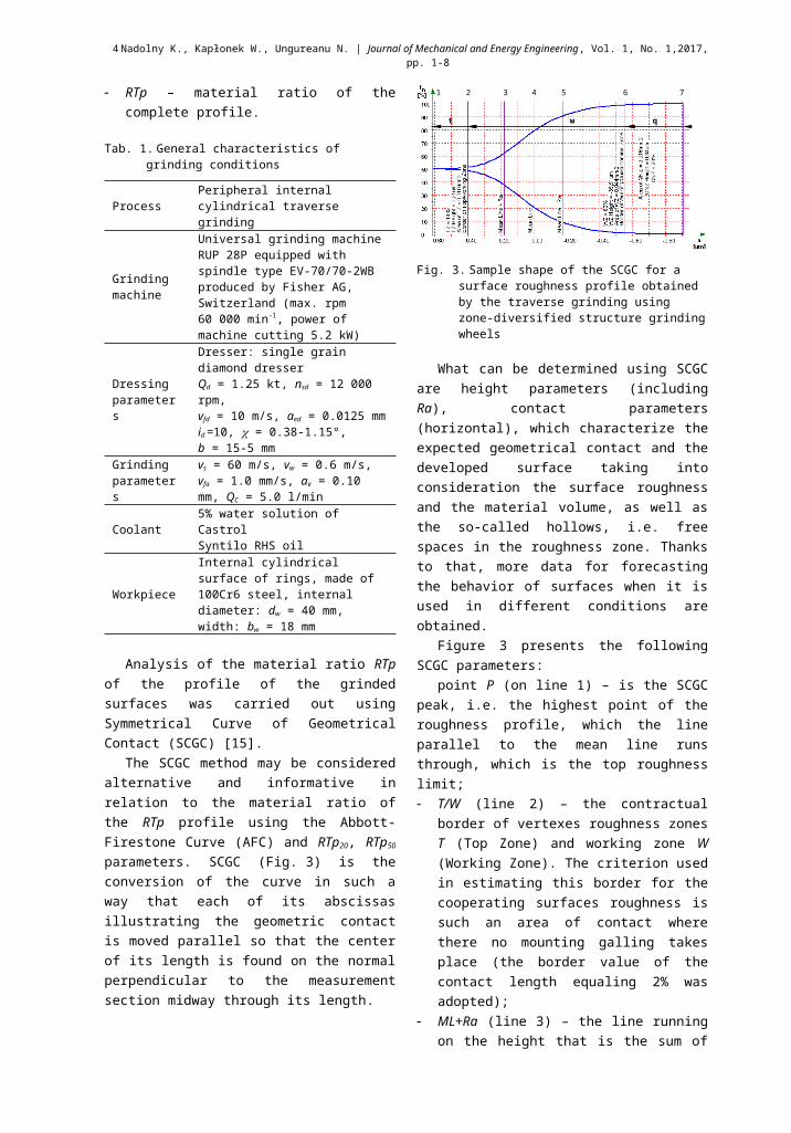
Analysis of the material ratio RTp of the profile of the grinded surfaces was carried out using Symmetrical Curve of Geometrical Contact (SCGC) [15].
The SCGC method may be considered alternative and informative in relation to the material ratio of the RTp profile using the Abbott-Firestone Curve (AFC) and RTp20, RTp50 parameters. SCGC (Fig. 3) is the conversion of the curve in such a way that each of its abscissas illustrating the geometric contact is moved parallel so that the center of its length is found on the normal perpendicular to the measurement section midway through its length.
t w q
1 2 3 4 5 6 7
Fig. 3. Sample shape of the SCGC for a surface roughness profile obtained by the traverse grinding using zone-diversified structure grinding wheels
What can be determined using SCGC are height parameters (including Ra), contact parameters (horizontal), which characterize the expected geometrical contact and the developed surface taking into consideration the surface roughness and the material volume, as well as the so-called hollows, i.e. free spaces in the roughness zone. Thanks to that, more data for forecasting the behavior of surfaces when it is used in different conditions are obtained.
Figure 3 presents the following SCGC parameters: point P (on line 1) – is the SCGC peak, i.e. the
highest point of the roughness profile, which the line
parallel to the mean line runs through, which is the top roughness limit; T/W (line 2) – the contractual border of vertexes
roughness zones T (Top Zone) and working zone W (Working Zone). The criterion used in estimating this border for the cooperating surfaces roughness is such an area of contact where there no mounting galling takes place (the border value of the contact length equaling 2% was adopted);
ML+Ra (line 3) – the line running on the height that is the sum of values of the profile mean line (ML – Mean Line) and the average Ra arithmetic roughness profile deviation;
ML (line 4) – the mean line of the roughness profile;
ML-Ra (line 5) – the line running on the height of ML-Ra;
W/Q (line 6) – contractual border of the roughness zones: working W and quasi-nominal zone Q, which runs on the height of contact that equals 98% of the measurement section;
D-D (on line 7) – the depth of SCGC pits, i.e. the lowest point of the roughness profile, which the line parallel to the mean line runs through, which is the bottom border of the roughness profile.The area between lines 1 and 2 is the vertexes
zone T with height of t, the one between lines 2 and 6 is the working area W with height of w, while the area between lines 6 and 7 determined the quasi-nominal zone Q with height q.
The SCGC curve is the border between the material (located under the curve) and the free spaces (above the curve). For this reason the print-out contains values of roughness zones surfaces (Area of Top Zone, Area of Working Zone). The surface of the quasi-nominal zone is the difference between the complete surface and the sum of surfaces of the working and top zones.
3.2. Grinding wheelsFive types of grinding wheels with zone-
diversified structure made using ceramic bond with glass-crystalline structure were applied. These tools were made from grains of polycrystalline white fused alumina 99A and microcrystalline sintered corundum type SG®. Table 2 presents the characteristics of grinding wheels selected for the tests. Designation of the grinding wheels given in Table 2 is the abbreviated technical characteristic adopted to simplify the presentation and description of the investigation results.
Both the hardness and the structure of particular grinding wheel zones remained unchanged for all types of grinding wheels used during the tests. Level K of hardness was applied to the rough grinding zone, and level I for the finish grinding zone. In both zones structure No. 7 was adopted.
4 Nadolny K., Kapłonek W., Ungureanu N. | Journal of Mechanical and Energy Engineering, Vol. 1, No. 1,2017, pp. 1-8
Tab. 2. Grinding wheels with zone-diversified structure designed for experimental investigations of the traverse internal cylindrical grinding
99A
/SG
*
1 - 35x20x10 - 99A/F46 K 7 V DG 70% /SG/F80 I 7 V DG 30%
SG/9
9A*
1 - 35x20x10 - SG/F46 K 7 V DG 70% /99A/F80 I 7 V DG 30%
SG/S
G*
1 - 35x20x10 - SG/F46 K 7 V DG 70% /SG/F80 I 7 V DG 30%
99A
100
%*
1 - 35x20x10 - 99A/F46 K 7 V DG 100%
SG 1
00%
*
1 - 35x20x10 - SG/F46 K 7 V DG 100%
3.3. Results and discussionThe results of the research indicate an increase in
values of the parameters describing the height features of the machined surface roughness profile Ra and Rz along with an increase in the value of the conic chamfer (Fig. 4).
Such a tendency is observed in the results registered for surfaces grinded using grinding wheels with zone-diversified structure (99A/SG, SG/99A and SG/SG), and for surfaces grinded without the finish grinding zone (99A 100% and SG 100%).
Fig. 4. Effect of the grinding wheel conic chamfer angle on the roughness profile elevation features of the machined surface: a) arithmetic mean deviation of the assessed profile Ra; b) maximum height of the profile within a sampling length Rz
This is caused by the chamfer width b shortening along with an increase of the angle. The short cone hinders effective realization of the rough grinding through the limited number of active grains that are simultaneously subject to increased strain. Accumu-lation of large-sized chips on a small area, despite the significant porosity, causes high intensity of clogging the abrasive tool active surface. Figure 5 presents SEM micrographs of the chips (Fig. 5a and 5b) and the cloggings (Fig. 5c and 5d) registered in the conic rough grinding zone of the grinding wheel active surface 99A/SG, SG/SG and SG/99A.
In such a case deformations of the machining system increase, because of which the cylindrical part of the wheel, apart from the function of rough grinding and sparking out, must also remove the remaining layer of the material. As a result, despite the long cylindrical smoothing out zone, the obtained surface roughness expressed with parameters Ra and Rz adopt the highest level for angle = 1.15, which corresponds to the conic chamfer width b = 5 mm.
The chart of changes of the RSm parameter which describing longitudinal parameters of the machined surface roughness reveal a decreasing tendency as the values of angle (Fig. 6a) drop.

Nadolny K., Kapłonek W., Ungureanu N. | Journal of Mechanical and Energy Engineering, Vol. 1, No. 1, 2017, pp. 1-8 5
Fig. 5. SEM micrographs of the chips and the smears on rough grinding zone of the GWAS obtained by JEOL JSM-5500LV for: a) 99A/SG grinding wheel; b) SG/SG grinding wheel; c) SG/SG grinding wheel; d) SG/99A grinding wheel
The decrease of the value of the mean roughness distance corresponds to the greater surface peak density, i.e. lesser smoothness of the obtained surface. The root-mean-square slope of the profile Rdq changes in the function of conic chamfer zone analogically to Ra and Rz parameters taking lowest values for = 0.38 (Fig. 6b).
What can be observed on charts of parameters Ra, Rz, RSm and Rdq are clear separation of lines representing results obtained during machining with grinding wheel SG/SG and SG 100% from lines presenting results of the remaining abrasive tools. The grinding wheels made solely from microcrystalline sintered corundum grains were characterized in the research by almost identical changeability of the results and visibly lower level of the aforementioned roughness parameters. This may be explained by the microcrystalline structure of such grains and their capability for self-sharpening. Even though in the remaining abrasive tools there were also zones made from grains SG® (except for tool 99A 100%), combined with polycrystalline grains of white fused alumina 99A, these grinding wheels did not provide equally smooth surfaces of the workpiece.
While analyzing charts of changes of participation of particular SCGC zones in the function of the angle (Fig. 7), it may be noticed that the greatest participation of the top zone and at the same time the lowest participation of the quasi-nominal zone (i.e. the least favorable conditions) was measured on surfaces grinded with the greatest conic chamfer angle ( = 1.15).
Fig. 6. Effect of the grinding wheel conic chamfer angle on the machined surface roughness parameters: a) mean width of profile elements, within a sampling length RSm; b) root-mean-square slope of the profile within a sampling length Rdq

6 Nadolny K., Kapłonek W., Ungureanu N. | Journal of Mechanical and Energy Engineering, Vol. 1, No. 1,2017, pp. 1-8
Fig. 7. Effect of the grinding wheel conic chamfer angle on the shares of the SCGC zones of the ground surface roughness: a) top zone T; b) working zone W; c) quasi-nominal zone Q
While the height of the working zone remained on more or less the same level, the participation of T and Q zones indicates obtaining the highest surface load capacity during machining with = 0.57. Further decrease of the conic chamfer angle value caused minor deterioration of the load capacity of the machined surfaces.
A change in the conic chamfer of the examined grinding wheels ranged from 0.38 to 1.15. It had, as indicated by the roughness parameter results, significant influence on the course of the examined
process and the quality of the workpieces. Such diversification of the angle did not, however, influence the registered values of the current power of the grinding wheel spindle P, which remained constant over the whole range of variability of the examined parameter (Fig. 8).
The obtained results of the research allows to conclude that the most advantageous values of the parameters describing grinded surface roughness, were obtained for the process realized with the conic chamfer of the abrasive tool = 0.38. This value of

Nadolny K., Kapłonek W., Ungureanu N. | Journal of Mechanical and Energy Engineering, Vol. 1, No. 1, 2017, pp. 1-8 7
the angle corresponds to the greatest chamfer width b = 15 mm. This means that the even distribution of the total machining allowance on a greater area of the grinding wheel conic chamfer allows for more effective operation of the rough grinding zone. As a result, the shorter cylindrical part of the grinding wheel removes a smaller volume of the material, which further guarantees lower roughness of the machined surface.
Fig. 8. Effect of the grinding wheel conic chamfer angle on the grinding power P (a) and the grinding power gain P (b)
4. CONCLUSIONS
The carried out research on the influence of the value of the grinding wheel conic chamfer angle on the roughness parameters of the machined surfaces and the grinding power prove that it is possible to optimize the conditions of the realization of the given process using angle . It must be, however, noticed that precise realization of conic chamfer in the field of low values of the angle requires application of special device.
The measured parameters of the geometric structure of the machined surfaces and the grinding power indicated, without any exception, that there was an improvement in the conditions of realization of the traverse internal cylindrical grinding process along with a drop in the value of the grinding wheel conic chamfer value.
The even distribution of the machining allowance over a greater surface of wider conic chamfer allowed for more effective removal of the material in the rough grinding zone and despite shortening of the cylindrical part of the grinding wheel contributed to improvement of the smoothness of the grinded surfaces. Simulta-neously, modification of the chamfer parameters did not have any significant influence on the grinding power.
The obtained research results form the basis for determining recommendations in terms of the suggested width of the conic chamfer performed on the abrasive tools’ active surface in such grinding processes. It may be assumed that the chamfer width should equal 90% of the rough grinding zone width b = 0.9T1. Such a value allows for maximum usage of the grinding wheel zone width designed with a view to intensive removal of material and leave a margin for motion towards the end of the chamfer in the direction of the cylindrical part, caused by progressive wear of the grinding wheel. The final value of the chamfer angle will result from the chamfer width b and the working engagement value ae.
AcknowledgementsPart of this work was supported by the Polish Ministry of
Science and Higher Education under Grant No. N503 214837. The Author wish to thank Mr. Andrzej Nowicki from Laboratory Team I for his help during experimental investigations of the grinding process, Mr. Krzysztof Maciejewski from the Laboratory of Metrology And Measurement Systems for stylus measurements as well as Mr. Ryszard Gritzman from Central Laboratory of the Institute of Technology and Education for acquisition of SEM micrographs.
NomenclatureSymbolsae – machining allowance (working engagement), μmb – conic chamfer width, mmbw – workpiece width, mmdw – workpiece diameter, mmid – number of dressing passesnsd – grinding wheel rotational speed while dressing,
rpmP – grinding power, WQc – coolant flow rate, l/minQd – diamond dresser mass, ktRa – arithmetic mean deviation of the assessed profile,
μmRz – maximum height of the profile within a sampling
length, μmRSm – mean width of profile elements, within a sampling
length, μmRdq – root-mean-square (RMS) slope of the profile
within a sampling length, °RTp – material ratio of the complete profile, %vfa – axial table feed speed while grinding, mm/svfd – axial table feed speed while dressing, mm/svs – grinding wheel peripheral speed, m/s

8 Nadolny K., Kapłonek W., Ungureanu N. | Journal of Mechanical and Energy Engineering, Vol. 1, No. 1,2017, pp. 1-8
vw – workpiece peripheral speed, m/s – angle of the grinding wheel conic chamfer, °
AcronymsAFC – Abbott-Firestone CurveCBN – Cubic Boron NitrideCNC – Computerized Numerical ControlGWAS – Grinding Wheel Active SurfaceSCGC – Symmetrical Curve of Geometrical Contact
References1. Nakajima T., Okamura K., Uno Y. (1984). Traverse
grinding techniques for improving both productivity and surface finish. In: SME International Grinding Conference, Fontana, WI, USA, paper no. Mr 84-534.
2. Klocke F., Hegener G., Deacu L. (1996). Hochleistungs-Aussenrund-Formschleifen. Innovatives Fertigungsverfahren vereint hohe Flexibilität und Produktivität. ZWF, Vol. 91, No. 4, pp. 164-167. (in German)
3. Klocke F., Hegener G. (1999). Schnell, gut und flexibel: Hochleistungs-Aussenrund-Formschleifen. IDR, Vol. 33, No. 2, pp. 153-160. (in German)
4. Xingas A. (1999). Next generation grinding. American Mechanist, Vol. 143, No. 9, pp. 58, 64.
5. Hegener G. (2000). In einem Zug geschliffen. Wellenförmige Werkstücke flexibel und mit hoher Leistung schleiftechnisch bearbeiten. Maschinenmarkt, Vol. 106, No. 16, pp. 38-43. (in German)
6. Weinert K., Finke M., Kötter D. (2003). Wirtschaftliche Alternative zum Hartdrehen. Innenrund-Schälschleifen steigert Flexibilität beim Schleifen von Futterteilen. Maschinenmarkt, 2003, Vol. 109, No. 48, pp. 44-47. (in German)
7. Lüetjens P., Mushardt H. (2004). Grinding out hardened parts. American Mechanist, Vol. 148, No. 3, pp. 52–59.
8. Webster J., Tricard M. (2004). Innovations in abrasive products for precision grinding. Annals of the CIRP, Vol. 53, No. 2, pp. 597-617.
9. Nadolny K. (2013). A review on single-pass grinding processes. Journal of Central South University of Technology, Vol. 20, No. 6, pp. 1502-1509.
10. Słowinski B., Nadolny K. (2007). Effective manufacturing method for automated diameter grinding. Journal of Advanced Mechanical Design, Systems, and Manufacturing, Vol. 1, No. 4, pp. 472-480.
11. Nadolny K., Plichta J. (2006). Possibilities of development in the single-pass internal cylindrical grinding. In: IEEE 19th International Conference on Systems Engineering ICSENG'08, Las Vegas, NV, USA, 19-21 August, paper no. ICSEng.2008.93, pp. 230-235.
12. Herman D., Plichta J., Nadolny K. (2006). New ceramic abrasive tools for rough and finishing grinding in one pass. Materials Science Forum, Vol. 526, pp. 163–168.
13. Nadolny K., Kaplonek W. (2012). Design of a device for precision shaping of the grinding wheel macro- and microgeometry. Journal of Central South University of Technology, Vol. 19, No. 1, pp. 135-143.
14. Nadolny K. (2013). Microdiscontinuities of the grinding wheel and their effects on its durability during internal cylindrical grinding. Machining Science and Technology, Vol. 17, No. 1, pp. 74-92.
15. Kaczmarek J. (1999). New approach of the chara-cteristics of surface microstereometry on the basis of facing. Advances in Manufacturing Science and Techno-logy, Vol. 23, No. 4, pp. 55-70.
Biographical notesKrzysztof Nadolny received his M.Sc. degree in Mechanics and Machine Design and next Ph.D (with honors) as well as D.Sc. degree in Machinery Construction and Operation from Koszalin University of Technology, in 2001, 2006 and 2013, respectively. Since 2006 he has been a researcher in the Department of Production Engineering at the Koszalin University of Technology, where currently he works as an associated professor and head of research-didactic team for production planning and control. His scientific interests focus on problems concerning machining processes and tools, efficiency, monitoring and diagnostics of machining processes as well as tribology. He has participated in 2 international and 3 national research projects, presenting results of his work at 10 international and 21 national conferences, published more than 180 scientific papers in international and national journals, book chapters, as well as conference proceedings. He is also the author of 4 monographs and 9 national patents.
Wojciech Kapłonek received his M.Sc. degree in Mechanics and Machine Design (specialization: Computer Applications in Engineering) and Ph.D degree (with honors) in Machinery Construction and Operation (specialisa-tion: Technical Metrology) from Koszalin University of Technology, in
2003 and 2010, respectively. Since 2007 he has been a researcher in the Department of Production Engineering at the Koszalin University of Technology, where currently he works as an assistant professor. He has participated in 2 international and 3 national research projects, as well as presenting results from his work at 6 international and 28 national conferences. His scientific interests focus on problems concerning 2D-3D measurements of surface roughness using optical methods (especially those, which utilise light scattering phenomenon), SEM and confocal microscopy, machine vision systems, as well as image processing and analysis techniques. He has published more than 120 scientific papers in various international and national journals, book chapters, and conference proceedings.
Nicolae Ungureanu received his MSc in Mechanical Engineering (specialisa-tion: mining machines and equipments) from Faculty of Mining Machines, Mining Institute of Petrosani in 1989, PhD from Technical University of Cluj Napoca in 1999 and Professor degree from North University of Baia Mare in 2004. Since 1994, after the work in SC
SIMATEC SA, has been a Researcher for the Department of Engineering and Technology Management, North University of Baia Mare, where currently he works as a Professor and Dean of the Faculty of Engineering. His scientific interest are focused on issues related with reliability and maintenance of systems.