jeita etr-7021 lead-free marking on assembled board 5 4. packaging unit for marking and its position...
TRANSCRIPT

Technical report of Japan Electronics and Information Technology Industries
Association
JEITA ETR-7021
Guidance for the Lead-Free Marking of Materials,
Components and Mounted Boards used in
Electronic and Electric Equipment
2004.6
Technical Standardization Committee on Surface Mount Technology Japan Electronic and Information Technology Industries Association

Guidance for the lead-free marking of materials, electronic components and mounted boards used in electronic and electric
equipment
Contents Preface 1
1. General 1 1.1 Scope 1 1.2 References 2
2. Terms and Definitions 2 2.1 Lead-Free 2 2.2 Electronic Component 2 2.3 Phase of Lead-Free Adoption 2 2.4 Minimum Unit of Packaging 3
3. Lead-Free Marking 4 3.1 General Items in the Marking of Lead-Free products 4 3.2 Lead-Free Marking for Materials of Solders 5 3.3 Lead-Free Marking for Electronic Devices 5 3.4 Lead-Free Marking on Assembled Board 5
4. Packaging Unit for Marking and its Position 7 4.1 General Items in Packaging Unit for Marking and its Position 7 4.2 Unit Required for Lead-Free Marking for Solder
and Position of Marking 7 4.3 Unit Required for Lead-Free Marking for Electronic Devices
and Position of Marking 8 4.4 Unit Required for Lead-Free Marking for Assembled Board
and Position of Marking 8
Additional Remarks 10 1. The Reason Why this Guidance was Developed 10 1.1 Basic Understanding of the Environmental Issues 10 1.2 Marking of Lead-Free Products 10

2. The Issues Needed to Clarify During the Development of this Guidance 11 2.1 Scope (1.1 of the Main Body of this Document) 11 2.2 References (1.2 of the Main Body of this Document) 11 2.3 Terms and Definitions (2. of the Main Body of this Document) 11 2.4 General Items in Marking (3.1 of the Main Body of this Document) 11 2.5 Lead-Free Marking to Materials for Solders (3.2 of
the Main Body of this Document) 12 2.6 Lead-Free Marking to Electronic Components/Devices (3.3 of the Main Body of this Document) 13 2.7 Lead-Free Marking to Assembled Boards (3.4 of the Main Body of this Document) 14 2.8 General Items in Packaging Unit for Marking and its Position (4.1 of the Main Body of this Document) 15 2.9 Unit Required for Lead-Free Marking for Solder and Position of Marking (4.2 of the Main Body of this Document) 15 2.10 Unit Required for Lead-Free Marking for an Electronic Component/Device and Position of Marking (4.3 of the Main Body of this Document) 15 2.11 Unit for Lead-Free Marking for a Board and Position of Marking (4.4 of the Main Body of this Document) 16 3 Comments from Recycling Agents 17 4. Intellectual Property Issues 18
Guidance for the lead-free marking of materials, electronic components and mounted boards used in electronic and electric equipment
Preface: There is a world trend to reduce the load to environment from electric and electronic products. The RoHS Directive, 2002/95/EC, issued by the European Parliament is the most important driving force to this trend. The Directive bans use of six substances as environmentally hazardous materials in all the electric and electronic products to be sold within EC countries after the 1st of July, 2006. The substances listed in the Directive include lead (Pb) based solder used in interconnection of components mounted onto board, plated metals used to electrodes and leads of components, and lead as a composition material of a component. The Japan Electronics and Information Technology Industries Association (hereafter abbreviated as JEITA) has been promoting adoption of the lead-free technology in electronics industry. Many manufacturers in Japan have successfully introduced the lead-free technology in their products. In the course of adoption of lead-free technology, there has arisen a need to clearly indicate that a specific product is lead-free. A project group was formed within JEITA to study the marking of lead-free products including electronic components and to develop a Guidance of Marking (labeling) to products employing lead-free technology. The present Guidance was prepared based on an extensive analysis of the questionnaire sent to leading manufacturers in Japan. 1. General 1.1 Scope: This Guidance is used to identify the phase of lead-free technology employed in the solder used in interconnections, materials for leads and terminals, electronic components and board mounted with components (hereafter stated as assembled board). The marking is used as the source information of the degree of lead-free technology employed in, 1) the products of material producers, materials to be supplied to electronic component or equipment manufacturers, 2) electronic components to be supplied to equipment manufacturers, 3) for repair of electric and electronic equipment, and 4) to reduce environmental load when recycle vendors discard the products as industrial waste by identifying the products, or parts, of the degree of lead-free technology employed. Standardized designation of the phase of lead-free technology employed is developed to promote the industry to cope with the requests from the society of the lead-free environment.

The applicable board for marking is the assembled board whether it is a main (mother) board or a sub-system (daughter) board with components mounted on using lead-free solder. 1.2 References 1) JEITA EDR-7605: 2004 Guidance to the Marking of lead-free packages for
semiconductor devices. 2) IEC 61190-1-3 Attachment materials for electronic assembly – Part 1-3: Requirements for electronic grade solder alloys and fluxed and non-fluxed solid solders for electronic soldering applications. 3) ISO 9453 Soft solder alloys – Chemical compositions and forms. 4) Lead-free Roadmap 2002 JEITA. 5) Study report on the standardization of marking for recycling of home appliances – First report – Prepared by the Working Group on the standardization of the recycling mark applicable to home appliances, Assessment Committee of the Japan Electric Manufacturers Association (JEMA). 6) RoHS Directive: Directive 2002/95/EC of the European Parliament and of the Council issued on 27 January 2003 on the restriction of the use of certain hazardous substances in electrical and electronic equipment. 2. Terms and Definitions The terms and their definitions are given below. 2.1 Lead-free The state that the content of lead (Pb) in solders, the relevant part of an electronic component including terminals and leads is less than 0.1 % in weight. Note: The threshold value (proposed) of lead (Pb) content described in both of the Lead-free Roadmap of JEITA and in the RoHS Directive is 0.1 % in weight. 2.2 Electronic component: The electronic component described in this document includes semiconductor devices, passive components (resistor, capacitor, inductor, varistor, thermister, etc.), connecting devices (connector, socket, switch, etc.), transducers (transformer, DC power supply, sensor, crystal oscillator, etc.), printed wiring boards (with components mounted on), and modules (hybrid IC, PA, VCO, etc.). 2.3 Phase of lead-free adoption: The levels of lead-free adoption specified in the

Lead-free Roadmap, 2002 are identified by the phases as specified below. a) Electronic component
Phase 1: Electronic components containing lead but exclude Phase 2 and Phase 3A. Phase 2: Terminals with which the device is mounted on a board, and the electrodes
of a device are lead-free. Lead may be contained in any constituent electronic component of the device itself, or in any material used in the device.
Phase 3A: All the internal connections, constructing components and all the materials used in a device are lead-free excluding the materials listed in the exemption list of the RoHS.
Phase 3: Lead is completely eliminated from interconnections, all the components and materials used in the device.
b) Assembled board
Phase 1: Assembled board contains lead but exclude Phase 2 and Phase 3A. Phase 2: Surface treatment of board, solder print and solder bath are all lead-free at
the level of board assembly, and lead (Pb) is eliminated in the interconnections of devices to the board. Lead may be contained in any electronic component of the device, or in any material used in the device.
Phase 3A: All the internal connections, constructing components and all materials used in a device are lead-free in the assembled board excluding the materials listed in the exemption list of the RoHS.
Phase 3: Lead is completely eliminated at the level of an assembled board.
2.4 Minimum unit of packaging This is the minimum unit of a package of products. Figure 1 shows examples of minimum units of packages including bag, reel, bulk case, stick magazine and tray. The minimum unit of packaging in this Guidance is the smallest package to which a label should be attached.

Reel Label Fan-folded container
Bulk case Bag
Figure 1 The minimum unit of package of electronic components
3. Lead-free Marking 3.1 General items in the Marking of Lead-free products The marking should be made on a package by means of printing, stamp printing, engraving, emboss, or seal that will
Tray

stay on the package and not easily be erased until the package is discarded. The marking should be easily recognizable of its content but the size of the marking is not specified. The colour of the marking is basically mono-colour. If there is an agreement between user and supplier on the marking, the agreed items have the priority. Use the symbol of the material when the material is included in the RoHS list and needs to be indicated in the label. 3.2 Lead-free Marking for materials of solders Unless otherwise agreed between user and supplier, marking of the composition of solder should be made using the element symbols to describe the alloy composition, or the composition symbols as shown in Table 1. It is not required to state the actual composition of each constituting element in the element designation. Table 1 may also be used for used solder and used solder paste.
Table 1 Examples of designation of lead-free solders
Solder Element designation
Composition symbol
Sn96.5Ag3Cu0.5
SnAgCu A30C5
Sn89Zn8Bi3 SnZnBi Z80B30
3.3 Lead-free Marking for electronic devices Unless otherwise agreed between user and supplier, the level of the presence of lead in a substance in a device is expressed by the Phase as given in Table 2.
Table 2 Marking for lead-free phases
Phases of lead-free Marking
Phase 1 Pb Phase 2 FTPb Phase 3A R-Pb * Phase 3 NoPb* Note * [R] and [F] are connected by [-] to make into one word.
a) The size of marking is not specified. Marking is required to be recognizable. b) The font and position of marking are arbitrary but it should be in one place of the same
label. c) The surrounding by the square of a mark is for easy recognition but its use is arbitrary.
3.4 Lead-free marking on assembled board a) The lead-free marking of an assembled board is principally made using the composition

symbols as specified in IEC 61190-1-3. Some examples are shown in Table 3. The size, colour or font of marking are not specified but should be recognizable.
Table 3 Examples of composition symbols of lead-free solders
Solder Composition symbol Sn96.5Ag3Cu0.5 A30C5
Sn99.3Cu0.7 C7 Sn89Zn8Bi3 Z80B30
Sn88In8Ag3.5Bi0.5 N80A35B5 b) When it is required to indicate the Phase of the lead-free realization degree, the Phase should be indicated together with the composition of solder used. Examples of the marking are shown in Figure 2. The arrangement of composition symbol and Logo mark is not specified but it should be made on one place. The marking should be easily recognizable of its content but the size of the marking is not specified.
A30C5 A30C5 A30C5
a) Phase 2 b) Phase 3A c) Phase 3
Figure 2 Examples of lead-free marking for assembled board
c) It is desirable to show all the solder compositions if multiple types of lead-free solder are used on a board (front and back surfaces). Note Symbol are separated by “/”, or “,”. Examples A30C5/N80A35B5/C7 or A30C5,N80A35B5,C7 Front reflow back reflow back flow Front reflow back reflow back flow
Pb PbPb

4 Packaging unit for marking and its position 4.1 General items in packaging unit for marking and its position The packaging unit on which a marking is made is the minimum package on which a space for a label is available. The position for the marking is the place that is easily identified by observation. 4.3 Unit required for lead-free marking for solder and position of marking Unless otherwise agreed between user and supplier, the unit of package of solder and position of marking to the package are specified in Table 4, together with examples of positions of marking in Figure 3. Table 4 may also be used for used solder and solder paste.
Table 4 Unit for lead-free marking and position of marking Type of solder Marking unit Position Arrangement Remarks
Bar solder
Rod itself, or minimum
packaging unit
Arbitrary
Arbitrary
-
Resin cored solder
Spool (bobbin), minimum
packaging unit
On label of spool (bobbin)
Arbitrary
Also applicable to wire solder
Solder paste Container On label of container
Arbitrary Also applicable to solder ball
Figure 3 Examples of designation of lead-free phase for solders

4.4 Unit required for lead-free marking for electronic devices and position of marking Unless otherwise agreed between user and supplier, the package unit of electronic devices and the position for marking are as specified in 2.4 in the space available on a label of the minimum package unit. Figure 4 shows an example of the position of marking. The same rule is applicable to the packages of terminal materials.
Lead-free marking (NoPb, R-Pb, FT-Pb, etc.)
Figure 4 Examples of designation of lead-free phase for electronic devices 4.5 Unit required for lead-free marking for assembled board and position of marking The assembled board should have the marking as specified in 3.4. The marking is to be made to the board with a size larger than 10 cm2. The marking should be made on an arbitrary position of the assembled board on a place easily identifiable. An example of the marking is shown in Figure 5. a) If there are multiple boards, the marking should be made as follows. 1) The marking is to be made as a principle on the representing board of the unit. Note When the phases of different boards combined into one unit are different, mark the phase of the lowest level of lead-free phase. 2) Separate markings are to be made on each board when separate boards are connected by a connector(s). b) It is desirable to mark all the types of solder used if multiple types of solder are used in the board(s) and to be marked on the board(s). c) If the marking made to an assembled board is not easily recognizable from above, a marking may be made on each composing board to a place recognizable from outside.
Xx

Figure 5 Examples of positions for designation of lead-free phase for assembled board
Sub-assembly board
Pb Pb
Connection using
Soldered connection
Soldered connection
Sub-assembly b d
Flexible cable
Sub-assembly b d
A30C5
Pb
A30C5
A30C5

Additional Remarks
The additional remarks stated here are not the parts of this Guidance but give additional information for better understanding of this Guidance. 1. The reason why this Guidance was developed 1.1 Basic understanding of the environmental issues The basic concept of the Fundamental Protection Law of the Environment is the effort of elimination or reduction of hazardous chemical substances generated from our industrial activities to reduce environment loads to establish continuing economical development and welfare for the human beings. The environmentally hazardous materials globally acknowledged include lead, mercury, cadmium, 6-valent chromium and some Br based fire retardant materials. There are regulations in various countries and areas for controlled emission of these materials. Lead (Pb) has been used in solders in electronics as the material for interconnection because of its superior mechanical and electrical properties and for its low cost. Lead-free solders have been developed from the consideration of environmental loading of lead. Solders used in manufacturing electronic products are being switched to lead-free solders these days. The Assembly Technology Standardization Committee of the JEITA has organized a project team to promote the use of lead-free solders by resolving problems realized in the use of lead-free solder in manufacturing. A Lead-free Roadmap Committee was first organized to attain consensus of the industry by providing them with the milestone to realization of lead-free technology and released “the Lead-free Roadmap 2002”. There was a common request from the industry that a marking for the use of lead-free materials should also be standardized to denote a product is at a specific stage of lead-free technology. 1.2 Marking of lead-free products The Study Group of the Lead-free Solder Assembly of the Assembly Technology Standardization Committee of JEITA organized a Lead-free Marking Guidance Development Project Group to develop markings of lead-free products (devices and equipment) together with the collaboration of Packaging Standardization for Mounting Components Committee in April 2003. Questionnaire was sent to companies involved in this country and replies were extensively analyzed together with exchange of comments and opinions with relevant trade organizations in this country. A study was also made on intellectual properties including the Logos and other designations of lead-free products. This “Guidance for the lead-free marking of materials, components and mounted board used in electronic and electric equipment” was finalized in April, 2004.

Comments from related four trade associations compiled by the Japan Electrical Manufactures’ Association (JEMA) were very valuable sources of information to develop this Guidance of lead-free marking. Discussion has been going on with relevant overseas organizations on the marking including IPC, JEDEC, or Soldertec, however, consensus has not been reached yet as of May, 2004. 2. The issues needed to clarify during the development of this Guidance 2.1 Scope (1.1 of the main body of this document) The scope was specified as the marking of the use of lead-free technology in materials, electronic devices, and assembled boards used in electronic and electric products. This Guidance was developed to provide the industry with the information of a standardized marking for the use of lead-free technology in various levels of incorporation of lead-free technology by reducing possible confusion that may arise among the industry for marking. It is our intention to support the smooth transition of the electronic industry to lead-free products to reduce the environmental load for the benefit of the humanity. 2.2 References (1.2 of the main body of this document) Both IEC 61190-3-1 and ISO 9453 are cited in this document as they are in the process of revision to include lead-free solders. The Lead-free Roadmap 2002 of JEITA are referenced to take into account of the [Phases] of lead-free levels. The Study Report on the Standardization of Recycling Marks prepared by JEMA was a good source of information on lead-free technology and relevant intellectual properties. The RoHS Directive provided us with the information on the hazardous materials. 2.3 Terms and definitions (2. of the main body of this document) The Pb value for lead-free technology was adopted from the Lead-free Roadmap 2002 and the TAC (Technical Adaptation Committee) of the RoHS Directive. The Phases of lead-free technology is adopted from the Lead-free Roadmap 2002. Consideration was made to take into account of some of the substances listed in the exemption list of the RoHS Directive. Phase 2A and Phase 3A were added later to our document (Phase 2A was the phase first considered based on the replies to the questionnaire). The term “component (or device)” was used first, however, the term “electronic component” was defined in this Guidance to avoid ambiguity that components (or devices) may refer to components used in home appliances. 2.4 General items in marking (3.1 of the main body of this document) The bottom line of the marking is that the mark made on a component stays on it until the component

is discarded for recycling, incineration or land-fill. The method of marking is not specified in this Guidance. The colour of marking is not specified here but it was agreed to be mono-colour for an economical reason. The size of a mark is not specified either if only it is clearly recognizable as a label on which the marking is made is different for various packages. The method of marking is not specified in this document. A patent application of marking printing (Patent Application Heisei 11-026896) by Ricoh was noted. There was a proposal in Europe that hazardous substances specified in the RoHS Directive were eliminated from products and the product was marked to show the product was in accordance with the Directive. In the Guidance developed in Japan indicates the chemical symbols of hazardous materials present in a product regardless of the specification in the RoHS Directive, a difference in the concept of designation of hazardous substances in this country and Europe. We tried to refer the RoHS Directive by using [RoHS-xx] or a Logo specifying the Phase of lead-free technology. We anticipated that the details of the RoHS Directive would be available soon, but the details were not available in early 2004 at the time of preparation of this document and the expected RoHS designation could not be included in this Guideline. However, we adopt a scheme of the designation of “R” for the restriction and used [R-xx] or a logo showing the lead-free Phase reflecting the concept in Europe. At the US-Euro-Japan Lead-free Summit meeting, US indicated that the indication of Phase 3 was sufficient and classification of Phases were not necessary based on the agreement reached in JEDEC/IPC/NEMI discussion but they addresses they would not oppose to the use of Phase classification. 2.5 Lead-free marking to materials for solders (3.2 of the main body of this document) The method of marking is studied incorporating comments of component and equipment manufacturers who actually use the lead-free solders in their products. There are various types of lead-free solders. Typical systems are Sn-Ag, Sn-Sb, Sn-Zn, Sn-Bi, or Sn-In systems. There is a need to identify the solder being used as there are few chances of mixing these solders in a production line from the point of soldering process control, and recycling of the left over solder. It is not possible to identify the composition of solder from its colour. This is why we recommend to mark also to the solder whether to solder itself or to a package of solder. At the US-Euro-Japan Lead-free Summit meeting, the US proposed to use “e-x” (x is a number and the size of the mark must be larger than 1.5 mm in diameter) to indicate solder composition based on the JEDEC/IPC/NEMI agreement. We did not adopt this

proposal as a table is needed to decipher the symbols and our intention to use common language that will be developed by IEC/ISO in near future. Both IEC 61190-1-3 and ISO 9453 are now under revision. We consider the contents of these documents may be incorporated into this guidance the revision is complete. There is information that short names of solder compositions are being considered in relevant committees. 2.6 Lead-free marking to electronic components/devices (3.3 of the main body of this document) The marking to electronic components was first studies only for marking of lead-free. The hazardous substances listed in the RoHS Directive include mercury, cadmium, 6-valent chromium and specified fire retardant brome compounds (PBB and PBDE). We noticed that there was also a request from equipment manufacturers to component suppliers to identify presence of such hazardous substances in addition to lead. We studied possible marking to identify including hazardous chemical substances in addition to lead (Pb). There are additional concerns in the industry on the use of PVC (polyvinyl chloride) and halogen free board materials. We needed to confine our drafting of marking hazardous chemicals to lead only as the details of the RoHS Directive were not released as of May 2004 as stated in 2.5 of this section, together with the advice we had from the Environment Strategy Project of the JEITA. We did study the possibility of including the following subjects though they were not included in the details of this Guideline a) There were requests from component manufacturers, first not to use multiple markings but a single marking to identify more than one such substance, and second marking of including hazardous chemical substances in compliance with the exemption list of the RoHS Directive. JEMA also asked if the marking of hazardous materials in addition to lead might be necessary. The statement on this subject is included in the main text of the Guideline. b) There were comments that PBB and PBDE should be separately marked, or PBB and PBDE should directly marked on a label. It was agreed to denote both of them just as Br. The comments from the materials manufacturers were such that it was difficult to separate them by chemical analysis, both of them could be treated similarly at the final treatment, and the designation of the compounds could easily be mistaken as Pb. It is desirable still to state clearly that only PBB and PBDE are the substances to be specified in the agreement between user and supplier or in the purchase order. It is also desirable to clearly state that only 6-valent chromium is the subject in dealing with 6-valent chromium. The content levels of the substances of interest should be in accordance with the levels agreed in the RoHS Directive.

c) Only the material in accordance to the RoHS Directive and does not contain the specified hazardous chemical substances is designated as [Eco] indicating that specific substance is environmentally friendly. It was shown in the study made by JEMA that this concept was acceptable if the designation was applicable only to electronic components. It is easily understandable that the term [Eco] means environmentally friendly, but the term is very vague and does not specify any quantitative specification. A question was raised if the term could be used only in lead-free technology. We decided not to use the term [Eco] but use instead the term [NoPb] also taking into account of the advise of the Environment Strategy Project of the JEITA. d) Similar regulations to RoHS Directive are also being investigated in other countries. The substances listed in the exemption list of the RoHS Directive such as some applications of lead are not definitely agreed and may change. There was an idea to state the year of publication of such a regulation and of the specified materials. We noticed the difficulty of identifying some chemical substances in such documents unless he/she was a real expert in chemistry. We did not include the year of publication of a document in the reference of this document. Use of a diamond shaped mark for identification is proposed in Europe taking into account of the RoHS Directive. The marking is basically for the marking of components supplied by component manufacturers to equipment manufacturers. The area needed for such a diamond shape label is rather large while the area available to a label on a package of component is limited. Printing of a diamond shaped mark is not easy compared to printing a square label. We did not adopt the use of a diamond shaped label but adopted a square label that requires less space for marking. The Semiconductor Packaging Sub-Committee of JEITA has specified to use a marking of [Pb-Free T.] to identify semiconductor devices whose terminals are lead-free in the document JEITA EDR-7605. This designation is only for the lead-free applied to terminals of a semiconductor device but does not specify any other part of a device. 2.7 Lead-free marking to assembled boards (3.4 of the main body of this document) The lead-free marking to assembled boards is incorporated into this document considering the analysis of the response to the questionnaire and interviews supplied from production lines, distribution, servicing, and recycling operations. It was made clear from recycling point of view that it is very desirable to have indications of names and contents of expensive metals such as gold, silver, platinum, indium and of metals difficult to isolate from other metals such as bismuth and zinc. Global service systems addressed a need to know the composition of solders used in equipment. These studies resulted in a conclusion that an indication of the information of the composition of solders used was necessary by means of easily recognizable logos. The proposed logo of JEDEC was
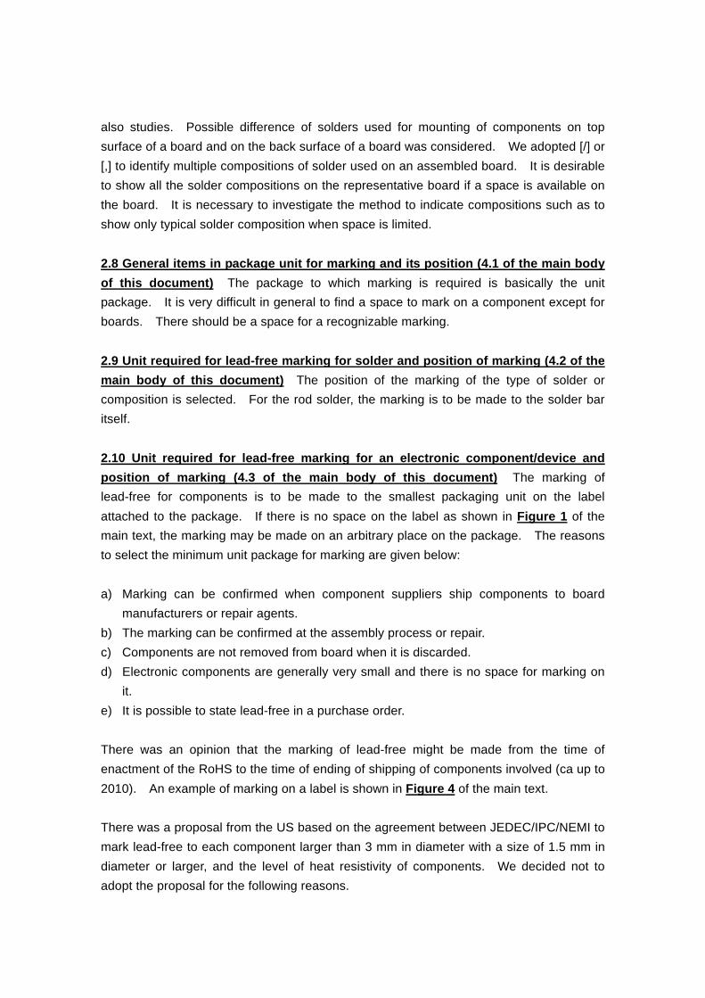
also studies. Possible difference of solders used for mounting of components on top surface of a board and on the back surface of a board was considered. We adopted [/] or [,] to identify multiple compositions of solder used on an assembled board. It is desirable to show all the solder compositions on the representative board if a space is available on the board. It is necessary to investigate the method to indicate compositions such as to show only typical solder composition when space is limited. 2.8 General items in package unit for marking and its position (4.1 of the main body of this document) The package to which marking is required is basically the unit package. It is very difficult in general to find a space to mark on a component except for boards. There should be a space for a recognizable marking. 2.9 Unit required for lead-free marking for solder and position of marking (4.2 of the main body of this document) The position of the marking of the type of solder or composition is selected. For the rod solder, the marking is to be made to the solder bar itself. 2.10 Unit required for lead-free marking for an electronic component/device and position of marking (4.3 of the main body of this document) The marking of lead-free for components is to be made to the smallest packaging unit on the label attached to the package. If there is no space on the label as shown in Figure 1 of the main text, the marking may be made on an arbitrary place on the package. The reasons to select the minimum unit package for marking are given below: a) Marking can be confirmed when component suppliers ship components to board
manufacturers or repair agents. b) The marking can be confirmed at the assembly process or repair. c) Components are not removed from board when it is discarded. d) Electronic components are generally very small and there is no space for marking on
it. e) It is possible to state lead-free in a purchase order. There was an opinion that the marking of lead-free might be made from the time of enactment of the RoHS to the time of ending of shipping of components involved (ca up to 2010). An example of marking on a label is shown in Figure 4 of the main text. There was a proposal from the US based on the agreement between JEDEC/IPC/NEMI to mark lead-free to each component larger than 3 mm in diameter with a size of 1.5 mm in diameter or larger, and the level of heat resistivity of components. We decided not to adopt the proposal for the following reasons.

There are items to be marked with priority on a component such as rating of the component, and it is difficult to find a space for the said marking. The significance of marking to components is for the transaction between user and supplier. Marking on the minimum package is suffice for the purpose. The designation of the heat resistivity was not adopted in our guideline with the same reason as above. The level of heat resistivity is closely related to the temperature profile in a production line. The statement of the peak temperature of the temperature profile is not sufficient information to evaluate heat resistivity of a component. Especially for reflow soldering, the heating method of a furnace is quite different from one furnace to the other. Furnaces of various generations are often used in a factory. It is not an easy task to use a simple designation of heat resistivity. We consider such a description may be made when there is sufficient space for such markings and when it is agree between user and supplier. 2.11 Unit for lead-free marking for a board and position of marking (4.4 of the main body of this document) The marking on a board with soldered sub-assemblies is made on the main board, and also to each board connected to the main board with a connector, a conclusion based on the replies to the questionnaire. The smallest unit is shown in this Guidance for marking but certainly each board may have marks if a place is available for marking. In the case boards with different phases of lead-free are connected by soldering, marking on each board is considered useful when the board is brought to repair. The position of marking on a board was agreed to be arbitrary as it is impractical to select a specific place as the positions of mounting electronic components are not predetermined and because of the present high density packaging technology. The only restriction is to mark on a board recognizable by observation from above the board in some way. When it is difficult to select an appropriate position, an arbitrary position may be selected on each board. Examples of marking on boards are given in Figure 5 of the main text. The minimum size of a board that is required for marking is 10 cm2 as recommended by the WEEE Directive. The lowest phase is to be marked when boards of different phases are combined into one body. There was a proposal from the US based on the agreement between JEDEC/IPC/NEMI to mark lead-free to each board larger than 10 cm2 with a size of 1.5 mm in diameter or

larger. There was also a proposal to include halogen-free to the marking on boards. These proposals were not included in this guideline in their original form as the present guideline is for the marking of lead-free technology only and the halogen-free issue could be handled by an agreement between user and supplier. The lowest phase of the boards is to be marked for connected boards with different phases of lead-free level by soldering 3 Comments from recycling agents Following comments were given from recycling agents. 1) Large characters or symbols are desirable. 2) It is desirable to indicate the presence of Au and Ag if they are present in solders. 3) It is desirable to indicate the presence of metals that are not easily separated such as
Bi and Zn (Information of the substances included is useful for smelting. The information may directly be related to the number of smelting in recycling.)
4) It is desirable to have a marking of the composition of solder used for a repair service of equipment. (Information may be useful in the selection of solder in hand soldering.)

5. Intellectual property issues The following applications are filed for intellectual property.
Company Type Number Contents Status Remarks Sharp Patent 2002-94198 Marking Matsushita Patent 2000-269614 Circuit Denied Senju Metals Patent 3365364 Marking Registered Matsushita Patent 2002-217504 Composition Conica Patent 2001-284752 Identification NEC Electr. Trade mark 2003-006249 Pb-FREE Withdrawn NEC Electr. Trade mark 2003-006250 Pb-FreeT Withdrawn Mitsubishi Trade mark 4664878 Mark Registered Sony Trade mark 4473342 L&F Registered Hitachi - - F mark Not applied Sanyo - - PbF,Pb(spec
i) Not applied
Micron Tech Trade mark US2017878 PB Advanced Micron D.
Trade mark US76/452078 76/452129 76/452114
PB-1000 PB-1500
In process
Pota & Pulfield
Trade mark Korean 369264
P&B Registered
Japan Filler Metals
Trade mark 44750789 PBF Registered
Oki Electr. Trade mark 4653768 LF in a leaf Registered