jd)thu - world radio history
TRANSCRIPT

_rolMiNim
JD)ThU ESTABLISHED 1917
JULY, ' 938 30c im U.S.A. and Canada I S m the United Kingdom; 2 - in Aus}rolosia No. 231
A 9 -10 Meter Mobile Phone Transmitter Barrage Directional Antenna Arrays An Acorn -Tube 56 -Mc. Superheterodyne "Mighty Mite " --A 20 -Watt All -Band Phone
Sr.. aJ.Y')'- -; ir.,l-m. www.americanradiohistory.com

THE BIGGER THEY ARE... the more space they take up. But not so with Cornell- Dubilieí s -C -D builds its capacitors compact] They're "over- size" in quality ... "under- size" in physical dimensions.
Here's C -D Type TJ -U -a Dykanol capacitor that packs more toughness into small space than a pair of blue- ribbon mules. DYKANOL -chlorinated -diphenyl, if you want it scientifically, is an extremely stable chemical compound and will not give off free chlorine no matter what the voltage stress or temperature.
For 28 years, Cornell -Dubilier has specialized in the manufacture of capacitors -exclusively. The result of that specialization has been the development of the world's finest and most complete line of capac- itors for every radio and electrical requirement.
TYPE T J -U NON- INFLAMMABLE, NON- EXPLOSIVE DYKANOL CAPACITOR It is extra -value features like these that mean more for your money when you buy C -D's.
YOUR MONEY CAN'T BUY YOU THIS MUCH
in any other condenser! * Hi- purity aluminum foil: lower r.f. resistance,
light weight. * High purity multi -laminated condenser tissue:
higher voltage breakdown, minimum leakage. * Vacuum dried and impregnated; lower equiva-
lent series resistance. * Hermetically sealed: not affected by moisture,
time or temperature up to 200° F. * Adequate terminal insulators: glazed porcelain
or bakelite according to rating. * Universal steel mounting strap: allows mount-
ing unit in any position. * Conservative D.C. rating: will operate continu-
ously even at 10% higher voltage than rating.
For complete catalog of C -D capacitors write NOW for NEW Cat. No.
TYPE HA NEW high voltage DYKANOL filter capacitors. Hermetically sealed in sturdy aluminum con- tainers, unaffected by moisture and heat. Can be mounted in- verted or upright. Conservative- ly rated.
TYPE 86 High voltage, heavy current - carrying mica transmitting ca- pacitors for amateur stations. Hermetically encased in non- hygroscopic glazed porcelain containers. Famous for their high efficiency, long -life and low -loss characteristics.
161 (Cable Address CORDU) PRODUCTS OF THE WORLD'S OLDEST AND LARGEST EXCLUSIVE MANUFACTURER OF CAPACITORS
CORNELL -D UBILIER ELECTRIC CORPORATION 1017 Hamilton Boulevard, South Plainfield, New Jersey
www.americanradiohistory.com

//wiz /Va Sags& itile The penalty of leadership is competitive sharp- shooting. Taylor Tubes' position as the leader has been gained by producing and engineering 75,000 better amateur transmitting tubes (commercial and industrial sales not included) . Radio amateurs know that Taylor Tubes has constantly worked to produce better tube values for them. The precision engineer- ing and production standards that bring you better quality tubes at the present low Taylor Tubes price level was earned only through the experience of TIME and ACTUAL PRODUCTION. In line with an old established policy, Taylor Tubes assures you that today's prices are consistent with a new high standard of quality. We pledge continued service to you, the radio amateurs of the world. We promise continued ingenuity in tube creating, not mere copying. We will always back our product with an absolute satisfaction guarantee. We further pledge allegiance to the better radio parts dealer. He is your best radio friend. Support him! Watch Taylor Tubes in 1938! Use Taylor Tubes and you'll get
"/i'l coe Waits PPJL 261144 //
Taylor Tubes, Inc. Chicago, Ill.
www.americanradiohistory.com

7460 BEVERLY BLVD., LOS ANGELES, CALIFORNIA 7.1k7"-Oil
Direct all correspondence to the home office at Las Angeles except os otherwise requested.
New York Office: 500 Fifth Avenue
Phone: CHickering 4 -6218
Chicago Office: 3618 No. Bernard Street
Phone: JUNiper 5575
W. W. Smith, WtiBCX EDITOR IN CHIEF
flay L. Dn.wley, W6DHG TECHNICAL
B. A. Ontiveros, W6FFF ASSOCIATE
K. V. H. Lansingh, W6QX ASSOCIATE
George D. Walker', W4CTO ASSISTANT
. . assisted by
Faust R. Gonsett, W6VR, Laboratorian Jack Rothman, W6KFQ, Laboratorian M. M. Lloyd, Managing Editor
Business Department
Los Angeles
K. V. R. Lansingh, Publisher
E. M. Johnson, Advertising Manager
Frank C. Jones, WDAJF E NO IN BERING
E. H. Conklin', W9F1,1 ASSOCIATE
Herbert Becker, W6QD ASSISTANT
liaius P. Turner', WI AY ASSISTANT
B. A. Ontiveros, W6FFF, Engineering Draftsman
Kennard Moore, W6PDB, Art Counsellor
New York V. R. Lansingh, Eastern General Manager
J. B. Carter, Asst. Advertising Manager
Chicago
G. Jasaitis, Circulation Manager C. W. Nelson, Asst. Advertising Manager
Address all correspondence and manuscripts to the home office at Los Angeles except as follows: I. Raddloddities, Strays, and the like may be sent to Rufus l'. Turner3. 2. Calls Heard may be sent to George Walker2; also dx news and station descriptions from
eastern America and from transatlantic countries. 3. Advertising inquiries may be directed to our nearest office, bitt all copy and cuts should
be sent direct to Los Angeles.
Unusable, unsolicited manuscripts will be destroyed unless accompanied by a stamped, addressed envelope.
1 512 N. Main St., Wheaton, Illinois. 2 Box 355, Winston- Salent, North Carolina. 3 106 Chilton Street, Cambridge, Massachusetts.
PRINCIPAL FOREIGN AGENTS
Europe: N. E. Read, 24, ('lurch Street, Oswestry, Shropshire, England. Australia: 'Thie Bulletin ", Box 252111B, Sydney; Slut ills, 183 Elizabeth St., Melbourne; Swain & Co., Ltd., Pitts St., Sydey. New Zealand: Te Ars Book Depot, Ltd., 64 Courtenay Place, \Yellin ion. South America: F. Stark, Caixa 2786, Sao Paulo; "Revissa Telegrafica," Peru 165, Buenos aires. Canada, John A. Holmes, 2888 E. First Avenue, Vancouver, B. C. South Africa: South African Radio Publi- cations, 40 Trust Buildings, Fox Street, Johannesburg.
RADIO. Entered as second -class matter. Published a; 7460 Beverly Boulevard, Los Angeles, Calif. 4
Radio, July, 1938 No. 231
RADIO is published ten times yearly (including enlarged special annual number) about the middle of the month preceding its date; August and September issues are omitted. Pub- lished by
RADIO TECHNICALVOBL9HER
>noo cvcni o[vw,o L09 ANGELES
IF YOU MOVE, notify us in advance: We cannot replace copies sent to your old address.
SUBSCRIPTION RATES, postpaid: U.S.A., Canada, Newfoundland, Cuba, and Mexico, $2.50 the year; two years, $4.00; (add 3% tax in Cali- fornia). Other independent American countries and Spain, $3.00 the year; two years, $5.00. Elsewhere (except New Zealand), $3.50 or 14s. Gd. the year; two years, $6.00 or fl 4s. 8d.ß Remittances must be payable at par its continental U.S.A. except as noted under "Remittances" below. New Zealand only, 18s. 6d. local currency, from Te Aro Book Depot, 64 Court- may Place, Wellington. Special Is- sues are included only with sub- scriptions of one -half year or longer. Refunds will be made on cancelled subscriptions at the difference be- tween the amount paid and the rate earned.
THREE YEAR SUBSCRIPTION, $5.00, net, In advance, in U.S.A. and Canada only. REGULAR ISSUE SINGLE COPY RATES: at newsstands, book stores, and radio parts dealers, 30c per copy in U.S.A. and Canada, ls. 8d. in the United Kingdom, 2s. in Australia and New Zealand. By mail, postpaid, from hone office, 30e In U.S.A., Canada, Newfoundland, Cuba, and Mexico; 35c in countries taking the $3.00 subscription rate; elsewhere, 40e or ls. 8d. Itegurding remittances, see below.
BACK ISSUES (when available), 5e extra; they will not be included in subscription. COPYRIGIIT, 1938, by Radio, Ltd. All rights reserved. Reproduction with- out permission is forbidden; per- mission is usually granted amateur papers on request. Title registered at United Stales Patent Office. Printed in U.S.A. by Glendale Printers, Glen- dale, Calif. ENTERED as second -class matter February 6, 1936 at the postoffice at Los Angeles, California, under the Act of March 3, 1879. Registered for transmission by post as a news- paper at the G.P.O., Wellington, New Zealand.
BRANCH OFFICES transact business with customers who call in person; mail orders should be sent only to Los Angeles.
RESPONSIBILITY will not be accept- ed for subscriptions placed with im - authorized agents. l'rospective sub- scribers are urged to inspect carefully the credentials of anyone soliciting their business. Agents are never author- ized to vary the rates above quoted.
1tEM1'1TTANCES must be payable at par in continental U.S.A., except as follows: Canadian postal notes accept- ed; please add 10e exchange to Ca- nadian checks below $2.50; British postal orders and cheques drawn on or payable at par in Loudon are accepted st rates (lusted in British currency. From elsewhere remit by Bank Drald (preferred) or international money order.
PRINTED in U.S.A.
www.americanradiohistory.com

"/fa'l ieel'ff of the Month J W8NQD and myself had just put the fin-
ishing touches on our new one -quarter kw. rig which we hoped would knock the Aussie's headsets for a loop of secondhand boomerangs when the following events occured.
We had just tightened up the last bolts, in- serted the T55's and were about to flick the switch that would fire up the rig when I hap- pened to glance in the general direction of the pile of junk we fondly call a power supply.
Holy smokes and little fish hooks! If there ain't the prettiest black and white pole kitty as ever I laid my two eyes on, all curled up be- tween the 866's to keep her nose warm.
You probably wonder why I so consistently refer to our visitor as "she ". We later came to the conclusion that no male of any critter could wreak as much havoc in so short a time as this pretty lady did.
To make a short story as long as possible, the hide off'n one of these despised but pretty creatures is worth its weight in T20's, provid- ing it is separated from its wearer -a task re- quiring tact, a gas mask, a suit of old clothes and a vacant lot miles from the nearest outpost of civilization.
Further examination of our intended victim showed among other things that she was dead to the world, her paw resting securely on the plate lead to one of the 866's, while her poste- rior parts were conveniently grounded to the metal chassis. What a position for immediate eviction of her soul from its worldly castle!
A flip of the switch at my elbow and two thousand volts of angry, buzzing a.c. would tear through her vitals, reducing her to a
smoldering crisp. True, I did feel somewhat like a cold- blooded killer, but the thought of that glistening T20 eased the pressure on my conscience, and with a prayer on my lips for the poor creature's soul, I did the dastardly deed.
With an ear -splitting shriek as if from a
lost soul in torment our intended victim bounded from her improvised death chair, tail high and laying down an overwhelming bar- rage of nauseating vapor, comparable to noth- ing since the Great War.
For fully two minutes she hurled her ef- fective offensive drive, while we, the enemy, shrieking oaths, choking and blinded, over- whelmed by this sudden and unexpected dis- play of power, retreated in rank disorder, at- tempting in our haste to back bodily through a
splid eight -inch cement wall. Failing in this, we climbed through a conveniently located win- dow, not hesitating to open same, while our op- ponent, dignified, and unhurried, head high, retired from the field of battle through the front door.
And now, dear readers, if on forty meters
*unit teuz.
PRIVATE LIFE
DIO As the spirit moves, we present in this column from time to time a bit of gossip about RADIO, its affiliated publications, and those who produce and distribute them -"From the private life of RADIO ".
Since our conscience bothers us, we inaugu- rate this column with an admission of guilt, that we swiped this idea lock, stoc. , and bar- rel from Time, and only hope tl- st we can make it half as interesting as they do.
Now to the most important news of he month:
Never happy in its inability to rear h its east- ern readers (who constitute the gr at major- ity) at what they consider as " rn time ", RADIO has completed arrangemen s for the October and succeeding issues to ! e printed and shipped from the plant of a lar ;e eastern publication printer, some 3000 rr les from its offices.
A record ?
So far as we know this constitutes ome sort . of a record. Does anyone know o another periodical whose editorial and busint ss offices are so widely separated from the pr )duction plant?
More details in the next issue; we're short on space this month.
A GENTLE
REMINDER That "Radio" publishes no Augur or
September issues.
The next issue is the October issue, out about September 25th.
5
www.americanradiohistory.com

some evening you hear a raspy r.a.c. note chirp-
ing merrily along and signing W8PMD, and
if in the opinion of yourself and others the key-
ing smells, remember, so does the operator.
Tite Opefrt lauton INFERNAL DIT - D A H S
Cleveland Heights, Ohio. Sirs:
While reading "The Open Forum" for June,
I happened to run across a letter written by A.
M. Croft. It was the usual, flimsy, no -code ar-
gument and it didn't bother me much until I
came across the words "infernal dit- dabs ". Bah!
The very idea of insulting our code in that manner.
Mr. Croft has never been on c.w., let alone the air, so how is he qualified to denounce it?
When you have been on c.w. and know it,
there is no "infernal dit -dahs" about it. After a while the boys on c.w. seem like they are liter- ally "talking" to you. Some of them have sweet filtered feminine voices, some have raucous TNT coughs, some have a T8x drone, some stutter and others talk smoothly, even some- times their voices crack, (QRH)
This and hundreds of other things make c.w. what it is today.
There are many foreign characteristics too, the "frequencyless" splutter of Cubans, the weak peep of the Japanese, etc., and might I
add the 25 -cycle trill of some of the boys in Ontario.
No, Mr. Croft, no "infernal dit- dahs" to those who know them any more than the Pone boys are "infernal mush -mouths" to the boys who do not know them!
LLOYD W. FROHRING, W8PMJ
For your BEGINNER FRIEND who doesn't have to have the very latest dope, we have a real bargain. We have a small oversupply of the following books. First come, first served!
The Jones Radio Handbook (1937) (456 pages; former price, $1.50)
Supplement to Jones Radio Handbook (1937) (78 pages; former price, 35c)
"Radio" Antenna Handbook, 1st edition 180 pages; former price, 50c)
While they last, all three for 041 00 Cash with order only; no "charge" orders.
ELSEWHERE, $1.25 POSTPAID In Continental U.S.A. Express Collect
[Canadian Postal Notes and British Postal Orders (5s. 2d.) Acceptable)
Radio, Ltd. 7460 Beverly Boulevard Los Angeles
6 www.americanradiohistory.com

July 1938 No. 231
The publishers assume no responsibility for statements made herein by con- tributors and correspondents, nor does publication indicate approval thereof.
flADIQ 'ot this vldt.te "Radio." 124ede,<2ed:
Frontispiece: Looking Back 8
ARTICLES
The Dx "Band Hopper" - - - - - - - 9
The Barrage Antenna -Ray L. Dawley, W6DHG - - - - 12
A Versatile Portable Receiver -John Bolmarcich, Jr., W3AXK 15
"The Mighty Mite" -John R. Griggs, W6KW - - - 19
Long Range Dx Prediction -E. H. Conklin - - - - - 24
An All -Wave Tuner Panel- Raymond P. Adams - - 27
A 9 -10 Meter Mobile Unit -F. R. Gonsett, W6VR - - 32
Better Phone Quality with Bass Suppression -J. N. A. Hawkins, W6AAR 35
Applications for the Cathode -Ray 'Scope, Part 1 - - - - 37
Acorn -Tube Five Meter Superhet -Arnold J. Ely, W8IPD - 42
56 Mc. Dx. Rampant! -E. H. Conklin - - - - 46 Streamlined is the Word -Frank Frimerman, W2FZ - - 52
Trouble Shooting in R. F. Stages -E. H. Conklin - 57
MISCELLANEOUS FEATURES
From the Private Life of RADIO 5 Pictorial by W1LIG - 61 "Yarnette of the Month" - 5 Buyer's Guide 96 QSL Card Contest Results - 18 Test Transmissions from Naval The Marketplace 97
Research Laboratory - - - 34 Advertising Index - - 97
DEPARTMENTS
Open Forum 6 Book Reviews 67
Dx 62 Question Box 67
Postscripts and Announcements - 66 56 Mc. 68
Yarn of the Month - 70
THE WORLDWIDE TECHNICAL AUTHORITY OF
AMATEUR, SHORTWAVE, AND EXPERIMENTAL RADIO
.7. www.americanradiohistory.com

2aohin9 Bach
Do you oldsters remember when you would have given your eye teeth for the equipment pictured above? In the background is one of the Adams -
Morgan company's old single slide tuners. To the left can be seen
the Nichols Electric company's "navy" loose coupler, while at the right is a genuine audiotron RJ4 detector, a relic of
pre -war days. It is perched on top of a P3 DeForest
one -stoge audio amplifier (remember them?). McMurdo Silver sent in the photo.
e
.g. www.americanradiohistory.com

THE MX "BflN11 HUPPf6" The somewhat strange -looking transmitter
shown in the accompanying photographs is a quick -band- change affair designed primarily for the medium -low power c.w. man interested in dx, which naturally means 40, 20, and 10 meters. If either a three -band antenna or three separate antennas are available, it is pos- sible to go from one band to another by merely throwing two switches and "redipping" one tuning condenser. While the last stage is not heavily enough excited for plate modulation at full input, the unit can be used as an exciter for either a 500 -watt plate -modulated amplifier or a kilowatt c.w. amplifier. The time re- quired for band -changing such a transmitter will be greatly reduced by the incorporation of the band -switching exciter.
However, we will assume in the following discussion that the rig is to be utilized as a 100 -watt c.w. transmitter on 40, 20, and 10 meters.
The unit consists essentially of a dynapush exciter* coupled inductively by means of un- tuned pick -up coils to a TZ -40 neutralized amplifier. While this system of coupling does
*February, 1938, RADIO, page 19.
The Dx Man's Transmitter-for use ou 111-. 20-, and IO-Meter
CAI'. Hands.
not drive
utilization of the maximum amount of drive available from the dynapush section, sufficient drive is obtained on all bands to drive the TZ -40 to from 20 to 30 ma. of grid current. This amount of excitation was found sufficient for operation of the TZ -40 at good efficiency. And it does greatly simplify the circuit over that required for bandswitching were a tuned grid circuit used for the TZ -40.
No practical difference in operation was ob- served between a T -40 and a TZ -40 with the value of grid leak specified in the diagram. Hence a TZ -40 was used, inasmuch as it per- mits oscillator keying without the necessity for fixed bias on the final amplifier stage. The resting current of a TZ -40 at 1000 plate volts is low enough at zero bias that the plate dissi- pation is not exceeded when there is no excita- tion. Possibly slightly higher efficiency could be obtained by use of a T -40 and a higher value of grid leak, but it is difficult to get enough voltage swing across the untuned pick- up coils for proper operation with a 7500- or 10,000 -ohm leak.
With the TZ -40 and 20- to 30 -ma. grid cur- rent through the 2000 -ohm leak, it is possible to obtain from 85 to 100 watts output at an input of 125 to 135 ma. at 1000 to 1050 volts.
www.americanradiohistory.com

6L6
10 ó40 Ra
20
/ d arco
6L6G
THE 20 M. TANK AND LINK COILS ARE SHOWN. THE 40 AND 10 M. COILS CONNECT TO THE BLANK SWITCH CONTACTS IN THE SAME WAY
lo L4
L -COIL SWITCH- -I
T240 FIL.
J3
R1- 50,000 -ohm 1-watt carbon
R2-300 ohms, 10 watts R3- 20,000 ohms, 10 watts R4- 15,000 ohms, 10 watts R3-10,000 ohms, 10 watts R0 -7500 ohms, 10 watts R7 -2000 ohms, 10 watts R, -1 -ohm c.t. resistor, 10
watts, connected to give 1/q ohm
RFC14- 2.5 -mh. midget r.f. chokes
RFC4- 2.5 -mh. r.f. choke, 250 ma.
C1 -50 -14(fd. double spaced midget (2000 - volt spacing)
C2 -50 -µpfd. double spaced midget
C3 -35 -ppfd. double spaced midget
C4 -5 -110d. double spaced midget
C3- 100 -ppfd. per section, 2000 -volt spacing
Q +525V.
C6- .006 -µfd. mica (1000 v.)
C7- .006 -0d. midget mica (500 v.)
C8- .006 -0d. mica C ---.006 -pfd. mica 0111- .0001 -pfd. mica Cii- .006 -1.(fd. midget
mica C12- .006 -pfd. mica C13- .006 -pfd. mica C44- .006 -pfd. mica C15 -.006 -0d. mica
(o0á1
ANT.
C18- .006 -µfd. midget mica
C1;- .006 -pfd. midget mica
Cis --.006 -0d. mica Li, L3, L3-See coil table L4- Turret type coil switch-
ing assembly M -0 -200 or 0 -250 ma.
d.c. T -7.5 volts at 6 amps.
(need not be mounted on some chassis if short, heavy leads are used)
Power Supplies
Both power supplies, the 500- to 550 -volt one for the 6L6's and the 1000 -volt one for the TZ -40, require no special mention other than the fact that they should possess good regula- tion, which indicates mercury vapor rectifiers and choke -input filter systems. The drain on the low voltage supply varies considerably de- pending upon whether one, two, or all three of the 6L6's are being used, and unless the sup- ply has good regulation, the voltage will rise to excessive values when only one 6L6 is being used. The supply may consist of a 700 -volt transformer, 83 rectifier, and single section choke -input filter with 4 to 8 1ifd. of 600 -volt oil -filled condenser, the transformer and choke being designed to handle 250 ma. The high voltage supply may consist of a 1150- to 1250 - volt transformer, 866JR rectifiers, swinging in- put choke, and 2 tfd. of 1000 -volt oil -filled condenser. The transformer and choke should be capable of handling 150 ma., and a bleeder of from 75,000 to 100,000 ohms (25 watts) should be used to keep the voltage from soar-
ing when the load is removed, endangering the 1000 -volt filter condenser.
The final tank assembly utilizes one of the new turret type band switching assemblies. First considered was the use of three separate tanks, thus doing away with the necessity for re- tuning the final amplifier plate tank when changing bands, but the additional cost and complications resulted in the incorporation of the arrangement illustrated. It takes only a second to retune the tank condenser when changing bands, and this seemed preferable to buying a couple of extra tank condensers.
Considerable trouble was experienced in get- ting the plate current to dip as it should on 10 meters when the tank was unloaded. Then it was discovered that the "floating" 40 -meter coil was hotter than the 10 -meter one; evidently it was resonating at 10 meters. Removing the 40 -meter coil permitted the 10 -meter coil to "dip" nearly as well as the 20 -meter one, prov- ing that the 40 -meter coil was stealing power from the 10 -meter coil, resulting in high mini- mum plate current.
To remedy this difficulty, two plates of thin
www.americanradiohistory.com

C O I L D A T A
40 -METER COIL
14 turns no. 18 d.c.c. close wound. Pickup coil, 8 turns no. 18 d.c.c. spaced 1:8 in. from cold end,
polarity as in wiring diagram.
20 -METER COIL
6 turns no. 18 enam. spaced to 5/8 in. Pickup coil, 5 turns no. 18 enom. spaced half diameter of wire, spaced 13 in. from cold end, polarity as
in wiring diagram.
10 -METER COIL
4 turns no. 18 enam. spaced to 11/4 in. Pickup coil, 21/3 turns interwound at cold end of coil,
polarity as in diagram.
All coils wound on standard 11/2-in. dia. forms, turns on space wound coils held in place with Duco cement. Turns and dimensions are quite critical, and may require pruning if physical lay- out much different from that illustrated is u!,ed.
galvanized iron were cut out with tin snips and soldered directly across the 40 -meter coil jacks as shown in the photograph, so arranged that about 2 square inches of overlap existed. These were bent in and out till the coil reso- nated at about 14 meters, effectively detuning the coil sufficiently that very little power is
absorbed. Too much capacity across the coil will cause it to resonate in the vicinity of 20 meters, and trouble will then be experienced with high minimum plate current on 20 meters. Just enough capacity should be used across the 40 -meter coil to reduce the 10 -meter energy picked up to a very low value, as evidenced by lack of "pencil sparks" on the ends of the 40- meter coil with the transmitter working on 10 meters; more capacity will result in difficulties with coupling between coils on 20 meters. It seems surprising that the floating 40 -meter coil can resonate at 10 meters, but a space wound coil has a much higher natural frequency than one would expect. Because of the low ratio of capacity to inductance, a couple of micromikes of shunt capacity will produce a great change in the resonant frequency.
The isolantite bandswitch for the dynapush portion is of the two -pole type. This enables one to use a single -gang switch for switching both the d.c. bias returns on the 6L6 -G's and the r.f. excitation to the TZ -40.
Coils
The dynapush coils are all wound on 11/2 -
inch forms as indicated in the coil table. It is very important that the coils L, and L2 be wound as specified, with polarity as shown in the wiring diagram. If this is not done, there will be a detuning effect and it will be necessary to touch up the condensers C, and C2 when changing bands. If wound as described, it will not be necessary to touch the condensers when changing bands with the same crystal, or a
crystal in the same part of the 40 -meter band. When going from one edge of the band to the other, however, it will be found desirable to retune the 6L6 tuning condensers, though not absolutely necessary.
There is no need to worry about detuning effect on the 10 -meter coil, because it either feeds the TZ -40 or doesn't work at all. It is not feeding another 6L6 -G part of the time as are the first two tanks. Hence it is not neces- sary to avoid capacitive coupling between wind -
(Continued on Page 88)
Underchassis view of the band hopper. Note layout of the vorious components.
II
www.americanradiohistory.com

iHf BflBRflGf RNTENNH
- -
,
I 0
2
t_
By RAY L. DAWLEY,'' W6DHG
FIGURE 1
LOW VOLTAGE HEAVY CURRENT TRANSFORMER
.01 MICA f
1'A ¡ LINE TO 3 %MITTER L..
II
110 V. A.C.
(A) shows current distribution in Sterba vertically - polarized curtain. Arrows indicate direction of carrent flow. (B) shows method of feeding heating current to
array. Length L should be kept small.
In recent years radio amateurs have become more and more aware of the wide usefulness of directional arrays made up of phased ele- ments. There was a time when many amateurs were of the opinion that the only way in which to obtain really good gain in an antenna sys- tem was to use either a rhombic or a long "V" antenna. Then, four or five years ago, several of the 20 -meter phones installed arrays con- sisting of a number of co- linear phased half - wave elements. The results obtained were good, and so it was left at about that status. But a short while after this E. J. Sterba, of the Bell Telephone Laboratories, published a paper discussing a type of antenna he had developed for use by A. T. & T. in its transoceanic tel- ephone circuits. Adaptations of this type of antenna have been found to give the greatest gain considering the amount of distance they take for their construction of any antenna com- monly used. This article will deal with these adaptations.
Close- Spacing, Out -of -Phase vs. Wide Spacing, In -Phase
There are two fundamentally different meth- ods of operating co- phased dipole elements in directional antenna systems. The first, employ-
12
ing close spacing with the dipoles out -of- phase, has received by far the greatest amount of pub- licity in the last year and a half or so, due primarily to an article, a classic in its field, by G. H. Brown that appeared in the January, 1937, I.R.E. Proceedings. The flat -top beam, antenna -director and antenna -director -reflector systems are among the best known of the close - spaced arrays. These systems have considerable merit, especially by the fact that reasonable gain may be obtained with a comparatively small amount of wire and in a small amount of space. But all these varieties of close- spaced arrays have the common disadvantage that their radiation resistance is quite high, thus making them somewhat diffcult to feed properly, causing high copper and insulation losses, and making them quite selective as to frequency of oper- ation.
The second method of operation of phased dipoles is with wide spacing (almost always with 1/ -wave spacing or very close to it) and with the two wires operating in- phase. These types of antennas have a comparatively high radiation resistance, hence are easy to feed properly and efficiently, have low inherent losses and are easily capable of operating over an entire amateur band with almost no loss in efficiency.
Of course, close- spaced arrays do have the undeniable advantage of compactness. And since there has been a great deal of interest shown of late among the phone men in rotata- ble arrays, close- spaced systems have received much publicity as their compactness and easy rotatability make them well suited to the job. But a number of the phone men, after having installed fancy little rotatable gadgets and hav- ing found that it doesn't make a whole lot of difference in which direction said rotatable gadgets are pointed after they have been in- stalled, are beginning to think that the c.w. men were right in leaning toward high -gain fixed beams oriented in a certain desired direc- tion. Of course, a large number of us do not
"Technical Editor, RADIO.
www.americanradiohistory.com

$ á
4 DB
S
4 z 4
Electrical layout of four simpler barrage
4
6 DB
FIGURE 2
antenna arrays shown with their approximate gain in decibels.
9S DB
have sufficient room on our assigned plot of ground to install any very extensive array or system of arrays; we are almost necessarily limited to some type of a small and compact rotatable array, or to small, medium -gain fixed beams.
The Sterba Curtain
The original Sterba curtain is the basis of the design of the beams to be shown in this article. The arrays as used by A.T.& T. con- sist of a large bank of vertically- polarized ele- ments as shown in A of figure 1. As can be seen from the diagram, the elements are con- tinuous and consist of one long piece of wire. This is an advantage where the antennas are used in locations where sleet or ice has a ten- dency to form on the wires in winter, since a
low -frequency alternating current can be passed through the wire to heat it enough that ice will not form. The method of feeding the heating current to the wires is shown in B of figure 1. Although this will be of interest to but few amateurs, some in unusually cold cli- mates may be able to make use of the idea. A low -voltage heavy -current filament transformer may be used to supply the heating current.
By simply turning this curtain on its side, and changing the feed position if desired, we have the type of horizontally-polarized system to be described in this article. These systems are shown in the "RADIO" HANDBOOK and the ANTENNA HANDBOOK; this article will deal with adaptations of the systems and with meth- ods of feed and installation.
The basic types of the arrays are shown in figure 2. In each case it can be seen that the arrays consist of a 3/4-wave long section at each end with either one, two or three double half - wave sections in between them, or, as in the most simple example, with only the two end sections connected together. The approximate gains of the different arrays, as compared to a 1/2 -wave doublet, are shown along with them.
The simplest of the arrays is interesting in that it is only 1/2 -wave long and 1/2 -wave high
and yet it gives a gain of approximately 4 db over a dipole in this small space. Also, it is quite easy to feed as its radiation resistance is
somewhat higher than that of a half -wave doublet. It can be fed by means of a shorted 1/4 -wave stub at the center, or it can be fed by transmission line of a characteristic imped- ance of about 125 ohms by breaking one of the end sections at the bend as shown in figure 3D. Either method of feed will be quite satis- factory for this array.
Methods of Feed
As was stated earlier in the article, these beams are quite easy to feed due to their high radiation resistance. And, due to their high radiation resistance, their effective Q is small. This allows them to be used, regardless of the
- 600 O TRANSMISSION LINE
60011 LINE
FIGURE 3
rJ
Permissible methods of feed.
13
www.americanradiohistory.com

J.S- PYREX INSULATORS,
TWIST AND SOLDER AT THESE POINTS
a- SPREADER INSULATORS SERVING WIRES
r a -r
FIGURE 4
Practical method of construction of barrage arrays. See text for discussion.
teed system, over a comparatively large fre- quency range; thus all may be operated over the 14 -Mc. band with little change, and very little change will be experienced when oper- ating over the entire 28 -Mc. band.
The permissible feed arrangements are shown in figure 3.
Probably the best method of feeding an array of this type when it is to have an even number of center '1/2 -wave elements (zero or two as in figure 2 A and C) and is to be symmetrical, is to feed it as in figure 3A. However, very little difference will be noted between the dif- ferent feed methods ; all those shown in figure 3 will be found quite suitable. The fact that these arrays consist of a continuous piece of wire assists in maintaining even current dis- tribution even though the array may be fed at one end. Feeding systems are further discussed in the section "Tuning Up."
Installation
As is the case with all multi -element an- tenna arrays, there is quite a difference in the approach to the problem between the pencil - and- paper, and the wire- and -insulator stages of the construction. However, in the installation and testing of quite a number of these arrays on different bands, a number of different ways in which not to make the installation have been learned. And, in the course of time, a number of short cuts to the proper way in which to put them up have been discovered.
The first thing to do in installing an antenna of this type is to determine what the 1/2 -wave and 1/4 -wave lengths are going to be at your operating frequency. And, it must be empha- sized, the conventional lengths given for oper- atión at these frequencies will not hold; con- ventional tables take into consideration the end
14
effects present in ordinary antennas. As there are no ends to the wires in these antennas (see diagram) there will be no end effects. Design tables have been given in the RADIO ANTENNA HANDBOOK, or the correct dimensions may be calculated by dividing the operating frequency in megacycles into 492, the answer to be in feet.
Then, upon looking at the diagrams as given in figure 2, figure how many 1/2 -wave sections of wire will be needed. All the antennas will require two pieces of wire a full wave long (for the two end sections) and two or more additional half -wave pieces. The '1/2 -wave phas- ing sections of the antennas are made up indi- vidually and later placed in the array, so figure on two 1/2 -wave pieces of wire for each of these sections. For example, take the array given in figure 2B. There will be two full -wave pieces of wire required for the end sections; then, since there are two 1/2 -wave phasing sections, four 1/2-wave pieces of wire will be required for these, and two additional 1/2 -wave pieces will be required for the other radiating sections.
The construction of this array, as an example, has been diagrammed in figure 4. Each of the pieces of wire that is to go to make up one of the 1/2 -wave phasing sections is made six inches longer than its theoretical length to allow three inches at each end for splicing. All other pieces are made the theoretical length. The 1/2 -wave phasing sections are made up first and each one consists of two 1/2 -wave pieces of wire, two 31/2" Pyrex antenna insulators (or other suitable strain insulators of about the same length) and enough 4" porcelain spreaders to allow them to be spaced about every five feet in the phasing section. Thus, for a 20 -meter array where these sections would be about 34 feet long, six spreaders would be required and the spacing between them would be about 4'10".
The ends of the wires are threaded through the two end strain insulators with about three inches of free end extending through. Then the so- called "serving wires" are placed around the insulators to hold them in place on the wires. These serving wires should be scraped so that they may be soldered in place when the array is assembled. Then the spreaders are placed along the wires and held in place by serving wires in the conventional manner.
The two end sections should then be made up from the two full -wave pieces of wire. Strain insulators are placed 1/4 -wave in from each end of these two wires and held in place by serving
(Continued on Page 94)
www.americanradiohistory.com

=tee Ell [IV By JOHN BOLMARCICH, JR.,' W3AXK
After having operated portable mobile on the five -meter band for the past two years it was decided to give ten -meter portable mobile a
try. The incentive for ten -meter operation was further increased by several descriptions of ten - meter mobile crystal -controlled transmitters which have appeared in recent issues of RADIO. Outstanding among these, in the writer's inter- est, was the one described by George M. Gren- ing in the April, 1937, issue of RADIO. A
variation upon this transmitter was constructed and the results obtained were excellent. But the problem of an efficient and versatile ten - meter receiver was not so easily solved.
The Receivers
The first receiver that was tried was a super - regenerative job. Although the sensitivity of this receiver was fairly good, the selectivity was very poor for operation in the crowded ten - meter band. The obvious solution was then to use a superheterodyne. And yet, to use a
superheterodyne without some kind of an effi-
cient noise silencer is almost out of the ques- tion for mobile work due to automobile igni- tion interference.
The answer, in my particular case, was to use a superheterodyne when parked upon the favorite hilltop and to use a superregenerative while in motion. It at first appeared that two receivers would be needed, but after thinking the problem over it was decided that one re-
ceiver could probably be made to act both as
superhet and superregenerator. The receiver to be described is the result of
considerable thought and experimentation along this line.
Choice of Intermediate Frequency
It is well known that to obtain good image rejection in a ten -meter superhet the inter- mediate frequency should be made as high as
possible. But a compromise must be reached since as the i.f. is increased, the gain and se-
lectivity in the i.f. amplifier decreases propor- tionately. Hence, the best solution seems to be to use a double -i.f. triple -detection super- heterodyne. It would at first appear, especially for mobile work, that the cost and complica- tions of such a receiver would be prohibitive. But such is not the case; the complete double i.f. channel, the audio stages and the power supply can be bought for somewhere between five and ten dollars. And the form in which it was purchased was that of a slightly used auto set.
The I.F. and Audio Channel
The market is flooded with auto radios of a couple of years back which have been traded in upon newer models. Of course, when you go out to buy one it is surprising how "un- flooded" the market can suddenly become, but it will usually be possible to convince some dealer that he has too many turn -in's on hand. By doing some shopping around I was able to get a six -tube superhet of well -known make for five dollars. The only thing wrong with the set was a torn speaker cone. This was in- expensively repaired, and when the set was re- aligned, it performed as well as new.
The receiver employed a 44 r.f. stage, a 77 mixer, a 44 i.f. stage, a 75 second detector, a.v.c. and first audio and a 42 in the output. An 84 was used as rectifier in the power sup- ply. Although the receiver is fairly old (1934 model), it compares favorably with the newer receivers. The basic circuits used in auto radios have changed little in the past three or four years except for the addition of push- button tuning in some of the 1938 sets. This, of course, would be a decided disadvantage in a receiver to be used as described.
By making a few minor changes, I now have a good ten -meter superheterodyne, a ten -meter superregenerator, a five -meter superregenerator,
*2524 Salmon St., Philadelphia, Pa.
15
www.americanradiohistory.com

4
a 160 -meter receiver, a marine receiver, and it is still a good broadcast set. And, if desired, the receiver may also be used as a superhetero- dyne on five by employing plug -in coils in the mixer stage.
Constructional Details
The first thing to do in the revision is to re- move the vibrator supply from the receiver cab- inet. The supply is then rebuilt into a small box and permanently installed in the car. When portable operation is desired, this power sup- ply (which, incidentally, is capable of an out- put of 250 volts at a drain of 50 ma.) is con- nected to the receiver by means of a power cable. The supply serves double duty in my particular case by also furnishing plate power to the modulator stage of the mobile trans- mitter.
Through the separation of the power supply
r-- R.F. / DET. T / Se
TC.
Figure 1.
Method of connecting additional pad- der condensers across broadcast coils of auto set for marine -band operation. C1- .0001 -pfd. mica, Si,-Triple-pole single -pole switch.
from the receiver, it is possible also to use the unit in the station and to operate it from a conventional a.c.- operated power supply. Its versatility is thereby greatly increased.
Through the removal of the power supply from the receiver, there is opened a space that is large for all the additional equipment that is required for the u.h.f. portion of the unit.
The next step is to remove one -tenth of the windings from the oscillator, detector and r.f. coils of the auto set. This brings the upper frequency range of the set to slightly above 2000 kc., thus allowing the 160 -meter amateur band to be covered by sacrificing the lower - frequency broadcast stations. But, by the use of a set of three padding condensers that can be shunted across the three b.c.l. coils of the set by a triple -pole single -throw switch, the range of the set is extended through the broad- cast band and down to about 380 kc. Another addition to the versatility of the set. This
16
method of connecting the padders across the b.c.1 coils is indicated in figure 1.
U.H.F. Operation
Two additional tubes with their associated coils, condensers, resistors, switches, and an audio transformer are added to the original complement of the auto set. A 36 is used as a space -charge detector -mixer for 28 -Mc. opera- tion, and a 37 is used as high -frequency oscil- lator when the receiver is operating as a u.h.f. superhet, and as a self -quenched oscillator when used as a superregenerator on ten and five. When the 37 is used as a superregener- ative oscillator in the latter mode of connection, the plate voltage is still applied to the 36 but there is nothing connected to its input or output circuits.
The Switching Arrangement
Switches Si, S2, S3i S,, S5, and Ss accomplish the complicated business of switching the re- ceiver from one mode of operation to another. Switch Si, located in the grid return of the 37 oscillator -superregenerator, changes the value of the grid -leak on this tube from about 20,000 ohms when operating as the h.f.o. of the super- heterodyne, to 100,000 ohms when the tube is
operating as a superregenerative detector on ten and five.
Switch S2, a s.p.d.t. toggle in the plate cir- cuit of the 37 tube, connects the plate return of this tube directly to the power supply when the receiver is operated as a superhet, or it forces the plate current to pass through the primary of an audio transformer whose sec- ondary is in the grid circuit of the 42 when the set is operated as a superregenerator. When S, has been thrown to this latter connection, S;,, controlling the heaters of all the tubes ex- cept the 42 and the 37, has been opened; thus the only source of audio for the grid of the 42 must come from the 37 detector.
Switch S3 is an on -off switch in the plate circuits of the 37 and 36 tubes used in the u.h.f. end of the receiver. This switch is opened when the balance of the auto set is to be used as a 160 -meter receiver, as a ship -band receiver or on the broadcast band.
Switch S, is the antenna switch which throws the external fish -pole antenna to the desired input circuit depending upon what type of operation is desired. When it is thrown to A, the set is to operate as a ten -meter superhet; when thrown to B, the set is capable of super - regenerative operation on ten and five; and
www.americanradiohistory.com

A
FIGURE 2.
CI- .0001 -pfd. mica condenser C5- 20upfd. midget variable conden-
sers C3- .00025 -pfd. mica condenser C4- .00005 -pfd. midget mica condenser Cs-Insulated hookup wire, twisted for
3" Cr, .0001 -pfd. mica by -pass condenser C7 -1.0 -pfd. 400 -volt tubular C5- 002 -pfd. mica condenser R1- 500,000 ohms, 1/2 -watt resistor R2- 250,000 ohms, 1/2 -watt resistor R3- 100,000 ohms, 1/2 -watt resistor R4- 25,000 ohms, 1 -watt resistor R5-20,000 ohms, 1 -watt resistor RFC1- 85 -mh. r.f. choke RFC2- 2.5 -mh., 125 -ma. r.f. choke Si-Detector superregen e ration or
straight oscillator switch S2 -Audio switch for superregenerative
or straight operation 53- U.h.f. front end on -off switch SI- Single -pole three -position antenna
switch S,5- Heater circuit on -off switch AFT -3:1 audio transformer Coils -See text for information
TO AUTO SET ANT. POST
54
53
FROM +5 C7 R5
Ti 00 TO GRID OF 42
A.F.T. STGE STAGE
Ss IN NEATER CIRCUIT OF ALL TUBES EXCEPT 37 OSCILLATOR AND 42 AUDIO
when placid upon C, the set may be operated upon the broadcast, 160 -meter or marine bands.
Switch S, has been mentioned before; it is the switch which removes the filament power from the tubes that are not used when the 37 and 42 are operating as a superregenerative receiver.
Switch SG (figure 1) is a triple -pole single - throw switch that places the .0001- 1.tfd. padder condensers across the oscillator, r.f. and de- tector coils of the b.c.I. part of the receiver when it is desired to receive the upper portion of the broadcast band and the 600 -800 meter marine band.
Ten -Meter Superhet Operation
When the entire receiver is operated on the 28 -Mc. band as a superheterodyne, the com- plete unit is running as a triple- detection double -i.f. set. The original i.f. of the auto set is 260 kc., and the front end of the b.c.l. part of the receiver is tuned to 1600 kc. Thus we get the advantages of both high and low i.f. and are not bothered by the disadvantages of each. The high frequency (1600 kc.) gives us good image rejection and the low (260 kc.) gives us good gain and high selectivity. A small amount of image interference may be experienced at twice the high i.f. from the desired signal (3200 kc. away), but since this interference will be out of the ten -meter band it ordinarily will not bother. If by any chance, it becomes bothersome, an acorn -tube r.f. stage will completely eliminate the trouble.
U.H.F. Coils The plug -in oscillator coils for the 37 tube
are wound of no. 14 wire, self supporting, and are mounted upon small strips of bakelite. Ba- nana plugs and jacks are used as connectors between the coil strip and the receptacle strip of the 37 stage. Only two coils are needed: one for five and the other for ten -meter opera- tion. The ten -meter coil will do both for superhet and superregen operation due to the two 20- µ1.tfd. tuning condensers across this coil. The oscillator is operated at a frequency 1600 kc. lower than the 36 mixer for superhet operation by turning the second 20- N.tfd. tun- ing condenser slightly in until the oscillator and mixer are aligned.
Since, at the present time, the receiver is used as a superhet only on ten, the first de- tector coil is soldered to its tuning condenser. If it is desired also to operate superhet on the 56 -Mc. band, this coil can be made plug -in.
Coil specifications are not given since they will be subject to considerable variation in individual adaptations. Conventional values as given in the 'RADIO- HANDBOOK will serve as a guide in winding these coils, but cut and try methods will be required to align them properly.
Shielding
As a last word let it be said that shielding is quite important in a receiver of this type due to the high gain of the auto set and to the fact that two oscillators will be operating at the same time when u.h.f. superhet operation is employed. Switch S, should be especially well shielded.
17
www.americanradiohistory.com

t fiy p n k :
Q S L
RONATION
.i.
I 9 3 7
YEAR
2Z Thta confirms our Qso of ....
- Tour siyoafs RST
_ Tour card will be >PPre<taem
73 and good Ina 3OHN HUNTER
- RADIO ,'' `
H,. B G n R T Z W 6 WAG RCC ,°!
63 Hervey RBad, Blackheath. Landan, S E 3
. Holly DDDOkYCR AND vs, OM, aaua
i \ i \ J1)
i
.ri ,r
, 1 r, \ !
` W8JZ Mf PLFASANi, PA NEO CULLER
$ti
..-
.
. .
'' o ì 3- 4s
Tj : -t
a
it }.' ,:.?,%I..., ii `--L
+'..s e. o ?,. .A.
.4',,k,
A. AI'
1 _if-
l:._ , \
Á
f
...4 E1 Pas Texas
i ' -1 . , ,
a .,..
. e Un .3
..... ' wisr8R
g
T-N, w 3 V x K 4s0 ORIG
Yf lfl ' . dEwADO 04/01.13. aft
4hM -.. tLION It, AO..Y.sA R:\Ttia a7f .w
a. c... W .s D e ̂ N v
M1 .wt '1 foi,,,...... + .
4hh >w {. .
r'de r}
CARD CONTEST RESULTS
Above are illustrated eight of the most attractive of the many cards received in the recent Q5L Contest
as announced in the January, 1938, RADIO. In the opinion of the judges, the first prize, a Taylor 814,
goes to W8NF of Wayne, Michigan, for the distinctiveness of the design of his card.
Second prize, a 4 -µfd. 600 -volt filter condenser, was awarded to W8JZ, Mount Pleasant, Pa., for the very
effective simplicity and cleanness of design shown in his QSL card.
However, all the cards shown on this page and a great many others not illustrated, scored so high that the judges did a great deal of head -scratching before they arrived at a decision.
18
www.americanradiohistory.com

An All -Band, 20- Watt, Phone-C.W. Transmitter--5 to
160 Meters!
HE MHTY N11í" By JOHN R. GRIGGS,* W6KW
"Build me a complete phone and c.w. trans- mitter for all band operation and keep the cost down as much as possible ... say about $35!"
That was the order recently given to the au- thor, who, with certain misgivings, undertook to satisfy the demand and surprised even him- self by developing a small, compact rig that is as efficient on 5 meters as it is on 160! In fact, it has even been operated successfully on 21/2 meters. It has both phone and c.w. avail- able on all bands and has proven to be ex- tremely flexible in operation- band -changing can be accomplished in only 30 seconds. And best of all, it may be built at a total cost, ex- clusive of tubes, microphone and crystal, not exceeding $35.
It will prove ideal for the newcomer to the "ham" game, and many an old timer will find it extremely handy for local rag- chews, either on 5 or 160, for portable use or for experi- menting on various bands with low power.
Construction
In designing this small transmitter, all the requirements that would be demanded of such a unit were outlined at the outset. First was the problem of flexibility, with efficiency and economy the next factors to be considered.
Thus it was that plug -in coils were chosen for
*3575 Boston Avenue, San Diego, Calif.
band coverage. Higher efficiency on the vari- ous bands is achieved by the use of a simple ar- rangement by which the L/C ratio is kept closer to correctness on all bands.
In accomplishing this a circuit was employed which requires the use of a two -section con- denser in both the crystal oscillator and final amplifier plate circuits. To explain the opera- tion, the two sections of the split- stator con- denser are connected to the coil socket in such a manner that the various combinations may be utilized simply by making the proper connec- tions within the coil form. In the 160 -meter oscillator coil, for example, both stator sections of the condenser are connected in parallel, mak- ing a total capacity of 200 i4ifd. to tune this coil. But on the other bands only one of the 100- 4tfd. sections is used (by a different set of connections) to tune them.
In the r.f. amplifier a dual 55- 1.t1tfd. conden- ser is used. By connecting the two sections in parallel a total capacity of 110 ltl.tfd. is avail- able to tune the 160- and 80 -meter coils. Then, by using only one of the two sections, the 40- and 20 -meter coils are tuned by a maximum capacity of 55 i .tfd. And, by connecting the two sections of the condenser in series as a split- stator, approximately 30 1tp.fd. of capacity is available to tune the coils for the 28- and 56- Mc. bands.
Since the bottom end of the four lower fre-
19
www.americanradiohistory.com

quency coils must be returned to ground for best efficiency, a .002 -gd. mica condenser (C ) is included in these coils and is plugged into the circuit in the proper position when the coil is inserted. This condenser is not used in the two higher frequency coils since both ends of the coil are floating on these bands. The r.f. return is obtained through the' grounded rotor of the split- stator condenser.
Metering
An economy feature of the rig is the use of only one meter to indicate the plate currents of the oscillator, the final amplifier and the modu- lator. A single meter (0 -100 ma. d.c.) with a new type of switch now readily available com- prise the metering circuit. Through this ar- rangement it is possible to note instantly the current flowing in each of the three above cir- cuits merely by switching the milliammeter into the desired circuit. The only disadvantage of this metering arrangement is that all cir- cuits to be metered must be operating from a
common plate supply; but since that is the case in this particular rig, the arrangement oper- ates perfectly. The switch referred to is the Yaxley 1313L.
Actual construction of the unit is made on a
metal chassis measuring only 10 "x17 "x3 ". This size makes the transmitter ideal for rack mount- ing, and yet it is small enough, being complete in itself, to be readily adapted to portable opera- tion by mounting the chassis in a convenient sized cabinet.
Power Supply
Only one power supply is required, involving a comparatively inexpensive receiver -type trans-
former, and a single 5Z3 rectifier, plus the usual filter components. The transformer should have a filament winding of 6.3 volts at a current rating of approximately 5 amperes. The plate winding should have a voltage rat- ing of 800 -900 volts, center- tapped, at a cur- rent rating of 200 ma. One triple 8- I.Ifd. 450 - volt filter condenser is used with a 20- henry, 250 -ma. filter choke, through which all plate supply current flows. The output of this choke supplies plate power to the modulator and r.f. stages. A bleeder of 20,000 ohms, 50 -watt ca- pacity, is placed across it to ground, to improve regulation. This is tapped at 250 volts for plate supply to the speech stages; this voltage is filtered again through a 30 -henry 30 -ma. choke and an 8 -ifd. 450 -volt condenser to in- sure humless operation of the low -level speech stages. The bleeder is also tapped at 175 volts for the screen grid of the crystal oscilla- tor.
R.F. Portion
The ever -present economy factor, plus the problem of flexible operation, made it neces- sary to limit the r.f. section to two stages. After thoroughly experimenting with the new Jones "sure -fire" crystal oscillator (April, 1938, RADIO) it was decided to incorporate this cir- cuit in the transmitter, utilizing a 6F6G as the oscillator tube. This tube is operated with full 400 volts on the plate, and, as stated in the previous paragraph, 175 volts on the screen grid. These voltages seemed to give the best operation on all bands, although somewhat less plate voltage could be used on the lower fre- quencies where the power output of the oscil- lator is greater.
20
The comparative simplicity of the under -chassis wiring is shown in this view. The meter switch can be seen in the center of the front drop of the chassis and the mounting plate for the speech -amplifier resistors and condensers can be seen along the right -hand edge.
www.americanradiohistory.com

110 V. A.C.
ALL HEATERS R
+175 V.
RN 7
R15
RFC2
C1 -8 -pfd. 450 -volt elec- trolytic
C9-16 -µfd. 450 -volt elec- trolytic
C3- .00035 -1tfd. mica C4- .0001 -µfd. mica C5-.01-pfd. mica C6 -.002 -pfd. mica C; -100 ppfd. per section,
split -stator variable C8- .0001 -pfd. mica C9-55 mid. per section,
3500 -volt spacing split - stator variable
C10-1.0-pfd. 400 -volt paper
C11, C,2 -.002 -pfd. mica C13 -.01 -µfd. mica C14- .002 -pfd. mica (in
160 -, 80 -, 40 -, and 20-
meter coils) C15-8-pfd. 450-volt elec-
trolytic CD,-.05-pfd. 400-volt tu-
bular C17-10-pfd. 25-volt tu-
bular C18-4-pfd. 450-volt elec-
trolytic C19-.05-pfd. 400-volt tu-
bular C20-10-pfd. 25-volt tu-
bular C21-.05-pfd. 400-volt tu-
bular C22-25-pfd. 25-volt tubu-
lar C23-10-pfd. 25-volt tu-
bular Ri-20,000-ohm, 50-watt
voltage divider R2- 50,000 ohms, 1 watt R3- 100,000 ohms, 1 watt R4 -1250 ohms, 10 watts R5- 50,000 ohms, 3 watts R6 -2 megohms, 1 watt R7 -2000 ohms, 1 watt R8- 250,000 ohms, 1 watt R9- 500,000 -ohm poten-
tiometer R,0 -5000 ohms, 1 watt R11- 100,000 ohms, 1 watt R12-1 50,000 ohms, 1 watt R13- 500,000 ohms, 1 watt R,4 -1000 ohms, 1 watt R15 -100 ohms, 10 watts RFC1, 2. 3- 2.5 -mh. 1 25-
ma. ri. chokes Si -Main a.c. line switch S2 -D.c. on -off switch
S3 -3- circuit, 3- position meter switch
54 -D. p. s. t. phone -c. w. switch
M -0 -100 d.c. m i l l i a m- meter
T5- 800 -900 c.t., 200 ma.; 6.3 volts, 5 amps.; 5 volts, 3 amps.
T2- Class -B input to single 6N7
T3- Class -B output from 6N7 to 8000 -ohm load, or to variable load
CH,- 20 -hy., 250 -ma. choke
CH2- 12 -hy., 30- ms.choke CSI- Oscillator coil socket CS2- Amplifier coil socket
As Frank Jones stated in his article concern- ing the oscillator circuit,' the value of the con- denser by- passing the crystal to ground is criti- cal and some adjustment may be necessary. However, a value of .00035 l,tfd. seemed to ef- fect the best operation on all bands.
Doubling in the plate circuit is accomplished merely by replacing the coil (at crystal fre- quency) with one of twice that frequency. Tun-
I"A 'Sure-Fire' Crystal Oscillator," Frank C. Jones, p. 47, April, 1938, RADIO.
ing for harmonic operation should be done carefully as the peak will be quite sharp.
Keying is accomplished by inserting a jack for a key plug in the cathode circuit of the os- cillator.
Coupling to the r.f. amplifier is accomplished by the time -tried capacitive method, using a mica condenser of .0001 Etfd. in value. This value is satisfactory on all bands.
Because of the fact that the amplifier must withstand modulation without reflecting an ap-
21
www.americanradiohistory.com

OSCILLATOR COILS ALL 1.5" DIAMETER
-160 METERS - 80 TURNS N. 20 ENAM. CLOSEWOUND
-80 METERS - 32 TURNS N° 20 ENAM. CLOSEWOUND
o
-40 METERS - 20 TURNS N° 20 ENAM. SPACED WIRE DIA.
-20 METERS- 6 TURNS N° 18 ENAM. SPACED 1/8"
°moo 0 -10 METERS -
3.5 TURNS N°18 ENAM. SPACED 1/4"
FINAL AMPLIFIER COILS N. 18 ENAMELED WIRE
ill
C14
160 METERS-0
2.5" DIA. SO TURNS CLOSE WOUND
80 METERS 30 TURNS CLOSEWOUND
E
C14 -40 METERS - 18 TURNS SPACED WIRE DIA.
1.5" DIA.
_ -20 METERS - 12 TURNS SPACED WIRE DIA.
-10 METERS - 0-..--0 1.5" DIA. 5.5 TURNS SPACED 3/16"
METERS DIA. S TURNS SPACED 1/4"
preciably varying load on the oscillator, a tube of extremely low driving power requirements was desired. And further, it was preferred that this tube be one requiring no neutraliza- tion, an important consideration in an all -band transmitter. The RCA -807 was found to com- ply in all respects.
Shielding
Shielding between the oscillator and final stages is necessary as the plug -in coils utilized are placed in the same plane for convenience and therefore have similar fields. The small plate of shielding, however, is easy to arrange, and does an effective job of isolating the two stages. To aid further in isolating the elements of the 807 from stray r.f. voltages, it is ad- visable to shield the tube itself by a metal can extending from the chassis up to the bottom of the tube's plate. This is effective in prevent- ing interference in the 807's grid circuit from the nearby plate tank condenser. The shield also reduces the effective internal capacity, al- lowing for increased efficiency on the higher frequency bands.
A cathode resistor of 1250 ohms, 10 -watt
22
rating, is used in the cathode circuit of the 807 to bias the tube to a safe level for c.w. operation (when excitation is intermittent) and to assist the grid leak bias for the best phone operation. Filament by -pass condensers are placed at the base of the 807 socket, and the center -tap of the filament winding is grounded at the transformer.
Coils
Information on coils used is given in the chart accompanying this article. However, it is well to remember that the coils should be wound so that the "hot" end of the coils (plate end) should be at the top of the form, farthest away from the chassis. Plate caps for the 807 are placed on leads soldered to the tops of the windings of the various final tank coils.
Care should be taken in the layout of the transmitter that both the oscillator and final coils are placed in such a manner as to be one diameter distant from all metallic objects nearby, such as transformers, chokes and con- densers or shields.
Isolantite sockets are used throughout in the r.f. section, both for tubes and. for coils. Bake- lite sockets, however, are suitable in all other cases, including the crystal mounting. Inci- dentally, it was found advisable to remove all the clips from the 5 -prong socket used for the crystal mounting, except for the two used to make connections. This prevents getting the crystal in the wrong position.
Two crystals can give all -band operation. A 160 -meter crystal will give harmonic operation in the oscillator to 80 meters and doubling in the final to 40. A 40 -meter crystal will allow doubling to 20 meters in the crystal stage and to 10 in the final. Good output can be obtained on 5 meters (when using a 40 -meter crystal) by quadrupling in the final stage. It has even been found that a good ten watts output could be obtained on ten meters by using an 80- meter crystal, doubling in the oscillator to 40 and quadrupling to 10 in the final. Excellent five -meter operation may be obtained by use of a 10 -meter crystal, although a 20 -meter crystal can be used, and it has even been pos- sible to make this transmitter deliver about 5
watts output on 21/2 meters!
Speech and Modulator
As the transmitter is designed for an input of approximately 20 watts, the speech ampli- fier and modulator must be capable of about ten watts audio output. Keeping the economy factor in mind, it was decided to use three
www.americanradiohistory.com

stages of speech amplification with a 6N7 as a class -B modulator. Provision was made for crystal microphone input, thus insuring good speech quality, and all three stages of speech, a 6F5, 6C5 and 6N7, are resistance coupled. Transformer coupling from the 6N7 class -A driver is used to achieve the proper step -down ratio to the grids of the 6N7 class -B modulator.
It will be noted that there is an r.f. choke in series with the microphone lead at the jack. This is sometimes not necessary but is con- sistent with good practice. All resistors and by -pass condensers are mounted on a bakelite mounting strip, at one end of the chassis. Care should be taken to isolate the speech leads (especially the input stages) by means of shielding and to place them as far as possible from any r.f. leads. Both the 6F5 and the 6C5 are connected as straight triodes although decoupling resistors are used to reduce possi- bility of audio feedback. The gain control operates in the grid circuit of the 6C5. The output of this stage is fed into the 6N7 class -A driver with the plates and grids connected in parallel. This gives ample power output to drive the grids of the following 6N7 class -B modulator.
Checking the Modulator
To check the operation of the 6N7 modu- lator, the meter may be switched into the plate lead, and static plate current should read 35 ma. It will be noted that because of the 400 volts used on the plates of the 6N7 modulator, it is necessary to bias the tube through a 100 -ohm 10 -watt wirewound resistor which is by- passed with a 10 -lifd. 25 -volt condenser. This con- denser is used to by -pass audio frequencies, as is the 1 pfd. used across the 125 -ohm resistor in the 807 cathode circuit.
Output of the 6N7 modulator is fed through a modulation transformer to the plate and screen grid circuit of the final amplifier, an RCA -807. It is important that a proper modu- lation transformer be chosen if correct opera- tion of the modulator is to be achieved. One firm manufactures a variable impedance ratio transformer of this type which sells at a rea- sonable price. The approximate Ioad presented by the r.f. amplifier is 8,000 ohms, when fully loaded to normal 20 watts. The secondary of the modulation transformer should be designed to carry the plate current of the r.f. amplifier, which should not exceed 65 ma. Typical op- erating conditions should show the 6N7 modu- lator drawing 100 ma. on peaks.
Angle front view of the complete transmitter.
R.f. feedback in the speech is negligible, even on the high frequency bands, except when the r.f. unit is not loaded to an antenna or dummy load! It is important to have sufficiently good antenna coupling to load the amplifier properly when operating on 5 or 10 meters. When such is the case, no trouble will be experienced with r.f. feedback in the speech. Grounding the metal chassis aids materially in reducing hum in the speech or carrier, except where it is necessary to run a long lead to ground. In such cases, it is usually better to leave it ungrounded.
Tuning
In first placing the transmitter in operation, the speech and modulator section may be tem- porarily disregarded, and full attention given to the r.f. portion. It is quite permissible to leave the speech and modulator tubes in their sockets, but the switch which disconnects their plate power should be in the off position before starting the following series of tests.
With the oscillator tube (6F6G) in its socket, plug in crystal and coil for same fre- quency, and place meter (by means of switch) in crystal plate circuit. Then apply B power. Rotate crystal tank condenser until a dip in current is noticed. Then tune for the greatest dip. Crystal oscillator plate current will vary, according to frequency used, anywhere from 11 to 30 ma. If no dip is found, check coils and connections. If connections are okay, and crystal is known to be active, try adding small fixed condenser (about .00005 pfd.) across coil. If unable to find dip, then remove the con- denser and short out several turns of the coil and try again. This should not be necessary, however, if the coil specifications are followed
[Continued on Page 74]
2°3 www.americanradiohistory.com

B y
.204, Range IA Atedictiaot
E . H . C O N K L I N
It might be said that there are two general methods of predicting the future -omitting such things as crystal balls -a close study of variations of the data being studied with a view to extending the variations and, secondly, a study of other factors which may have a similar movement or a causal (not casual) relationship to the thing in which we are interested. An ex- ample of the first is the "dx cycle" from which conditions a few months ahead have been pre- dicted with fair accuracy; and of the second, attempts to show what is going to happen to our bands based on the change in sunspot activity.
Amateurs appear to have given but little thought to the comparison of radio conditions with other data such as variations in the earth's magnetic field and sunspots, although a few isolated workers have made a study of these things. There has been almost a complete ab- sence of any quantitat've record of radio condi- tions in amateur publications, going back a few years. However, acknowledging that the layers of the ionosphere are very important to radio, we can turn to a paper written by Elbert B. Judson,1 W3AFU- W3GBI, in 1936 and ex- tend the study to the present time. By deter- mining the ionosphere layer that is supporting transmission at a given frequency, predictions become possible if changes in the layer can be predicted.
Layer Height
Of the more important layers, the E and F2 are of most interest to us. Ordinarily, the E layer which has a virtual height of about 100 to 120 kilometers (varying around 70 miles), is the medium for transmission on our lowest frequency bands only, although occasionally strong sporadic reflections take place from it permitting it to control transmission even down
*Associate Editor, RADIO.
'E. B. Judson, "Comparison of Data on the Iono- sphere, Sunspots, and Terrestial Magnetism," Nat. Bur. Stand. Jour. Res., vol. 17, pp. 323 -330; Sep- tember, 1936. Also, the same paper will be found in Proc. I.R.E., vol. 25, p. 38; January, 1937.
24
to five meters. Of most interest is the F2
region, about 200 to 500 kilometers (124 -310 miles) in virtual height, depending on the time of day and the season, and the F layer which is generally formed at night by the combina- tion of the F1 and F2 layers.
From ionosphere measurements, two impor- tant types of data are obtained2: the virtual height of the layers, and the penetration fre- quency or critical frequency above which re- flections will not return the signal directly downward.
Zurich Sunspot Numbers
Mr. Judson used the Zürich provisional sun- spot numbers in comparison with the magnetic character number for each day as reported by the Cheltenham Magnetic Observatory of the U.S. Coast and Geodetic Survey. The iono- sphere data of the National Bureau of Standards for noon, Eastern time, was used because the majority of observations during 1930, 1931 and 1932 were taken around that time, although the noon values are not necessarily the daily maximum points.
Critical frequencies from 1934 through 1937 were generally increasing, as were sunspot num- bers and magnetic activity. An examination of individual days in 1934 and 1935 showed no consistent agreement between the curves for critical frequency and those for the cosmic data.
Critical Frequency
Monthly averages are plotted in figure 1. The critical frequency and virtual height curves show the marked seasonal variation repeating each year and usually having high daytime critical frequencies around February and November, with much lower values in the summer. It is this seasonal factor which appears to govern 28 -Mc. transmission across the Atlantic. It is interesting to note that the virtual height is generally low when the critical frequency is high, a condition which also has been found to
E. H. Conklin, "New Ionosphere Broadcasts," RADIO, October, 1937, p. 26.
www.americanradiohistory.com

14000
13000
13100
2000
12400
12000
0 11600
6 112C0
10300
1ao° W 10000
w 9600
J 0200
u
1C
Vl M
<
3
IIIIIÌÌÌIIÌÌIÌÌÌÌÌÌÌÌÌÌÌÌÌÌÌIÌÌÌÌÌÌÌÌÌIÌIÌÌÌIIÌIIÌÌIIIIÌIIIIIIIÌIÌÌIIIIIÌÌIIII1ÌÌ ÌÌÌÌÌÌÌÌÌÌÌ 11111111111111111111111111111111111111111111111111111111111111111111111111111H11111J1 1111111 11111 SUNSPOTS (ZUR CH) IIIIIIIIIIIIIIIIIl1111111111111111111111111111111111111119111/111111
11111111111111111111111111111111I11111II111IIIIIIIIIIl11I1111111111111111111111fi1111111mil
IIIIIIIIIIIIIIIIIIIIIIIIIIIIIIUIIIIIIIIIIIIU IIIIIIIIIIIIIIIIIIIIY.HII/IIIIIIIIIIIIIIIIIIIII IIIIIIIIIIIIIIIIIIIIIIIIIU IIIIIIIIIIIIIIIIIIIIIIIIIIIUIIIIIII%11111111111 UIIIIII UIIIIIIII IIIIIIIIIIIIIIIIIIIIIIIIIIIIIIIIIIIIIIIIIIIIIIIIIIIIIIIIII111171IUIIIIIIIIIIIIIIIIIIIIIIIIII II!0IL1IUIIUIIIIIIIUIIIUUIII111111111IIIIIIIII111111M111IIIIIIIIIIIIIIIIIIIIIIIIIIII IIIII11II0IIIIIIIIIIIIIIIIIIIIIIIIIIIIIIIIIIIIIIIIII11iUIIIIIIIIIIIIIIIIIIIIIIIIIIIIIIIIII 111111111111íi .5u1IIAOIIIIIIi01111111111111it11111M11/11111111111111111111111111111111111 1111111111111111111111111:í111I1C!.:11!111,íilllílì:111111111111111111111111111111111111111111
11111111111111111111111111111111111111111111111111111111111111111111111111111111111111MU111 11111111111111111111111111111111111111111111111111111111111111111111111111111111111111111111 11 CRITICAL FREQUENCY. F2 REGION IIIIIIIIIIIIIIIIIIIIIIIIIIIIIIIIIIIIIIUIIUII1/1V1IUIUaIIV II II EXTRA-0RD NARY RAY 11111111111111111111111111111111111111111111111111 1111111111 111 11 1200 E.S.T. UIUIIIIIIIIIIIIIIIIIIIIIIIIIIIIll1111I111111II1II IIIIIIIIIIII IIIIIIIIIIIIIIIIIIIIIIIIIIIIIIIIIIIIIIIIIIIIIIIIIIIIIIIIIIIIIIIIIIIIIIIIIIIIIIIII11I11HU11I IIIIIIIIIIIIIIIIIIIIIIIIIIIIIIIIIIIIIIIIIIIIIIIIIIIIIIIIIIIIII111/IIIIIIIIIIIIII161111/NU1 IIIIIIIIIIIIII11II1111111111111111111111111111111IIIIIIIIIIIIIIIJ1IIIIIIIIII1111U11111111 11 IIIIIIIIIIII1111IIIIII11I1111111111111I111111111111111IIIIIIIII41111IIIIIIIIII1111111I111111I IIIIII1111IIIIIIIIIIIIIIII11111111111111111III11IIIIIIIIIIIII1111I11IIIIIII11I1111III 1111111
IIIIIIIIIIIIIIIIIIIIIIIIIIIIIIIIIIIIIIIIIIIIIIIIIIIIIIIIIIIIIIIIIII1I1IIIII11111111IIIIIIIIIIII IIIIIIIIIIIIIIIIIIIIIIIIIIIIIIIIIUIIIIIIIIIIIIIIIIIIIIIIIIUIIIIIIIII%IIII1111111111/111IIIII III011IIIIIIIIIIIIIIIIIIIIIIIIIIIIIIIIII111III1IIIIIIIIIIIII111111111d1111IIIIIII1/11IlIIIII IIIII111911I1IIIIIIIUIIIIIIIIII11IlIIIIlI1I1lIIIIIIIIIIIIIIIIIIIIIIIII111I11IIl1IIlII1lIIIIII 11111111111111111H1111111111111111111111111111111111/1111111111 11111111T 111111111111111M11 111111111111111111111111111111111111I1111111I111111111C11111111 UIUUI/111111111111111111111 11111111111111111111111111151I1UUIUmmmnul1r!U1U 111111111111111111111111111 1111111111111111115ì1111111J1ü1111111/1111111111/,1111/1U'/J11111111111111111111111111111111 U IIIIIIIIIIIIII11111,111111111111111111111111Ca11/11111111111'111111111111111111111111U11111
ÌIÌIIIIIIIIIIIIIIIIÌIÌÌIÌ/ÌÌIÌI ÌIIÌÌIIIIIIÌÌ ÌÌIIIIÌIÌIIÌIIIIIIIIIIIIIÌIIIÌÌIIIIIIñiÌIIII 11111111111111111111111111111111111111111111111111111111111111111111111I111111111111111111111 11 VIRTUAL HEIGHT IIIIIIIIIIIIIIIIIIIJ111111111111111111111111/ 1111111111_11111111119111111111 U F2 REGION 111111111IIIIIIh 111711II1I1/, 19111I111P. 11111111115C11111111110III11III 11 1200 EST 1111M1111111111111G111111C /111 111111Ì11117111111111 17111111111111111111 111111111111111111 / 1111111711171111111 .I5ì11111111915 11111111111 ' /11111111111PIII MIIFG1 11111111111111111111111111UN11111111111111111111111111111111111 M1111111....á1111110111 111111111111111111111111111111111111111111111111111111111111111111111111111111111111111111111 IIIIU111111111111111111111111111111111111111111111111III111111111111111111111111111111111111
IIIIIIIIIIIIIIIIIIIIIIIIIIIIIIIIIIÌÌÌÌIIIIIIIIIIIIIIIIIIIIIIIIIIIIIIII IIIIIIIIIIIIIINIIIIII 111111111111111111111111111111U1111111111111111111111111111111111111111111111111111111111111 11111111111111111111111111111111111111111111111111111111111111111111111111111U111111111111111 111 VARIAI ON IN HOR ZONTAL COMPONENT 1111111111111111111111111111111 11111111 1111
11 OF EARTH'S MAGNETIC FIELD (CHELTENHAM IIIUIIIIlIIl1111III11111111I111UII ' 1
IIIIIIIIIIIIIIIIIIIIIIIIIIIIIIIIIII11111111111 IIIIIIIIIIIlIIllllll11111U1 1
IIIIIIUIIIIIIIIIIIIIIIIIIIIIIIIIIIIIIIIIIIIIIIIIIIIIIIIIIIIIIIIIIIIII11111 1111111111111111111111111111111111111111111111111111111111111111111111r111IIU1I WUUIIUUUUIU1Inm11UUU1UUUU1mnn1UUU UUUU15nmm1/1__ -_ .
0 111.1111111!P51111/d11:1111111/111111111111Uh.1111111118.11Unu1n:!v:Uli.wE1 N11 3111111111/,IIIIIL 111111:111111!511!71911111G,1d111111!ll/U16!1U11111111n11111111111H1111 30 IIIIGC51111111111111111115:111111111!..N1111G141111111111U1111111111111 111111111111 ;, IIIIIIIIIIIIIIIIIIIIIIIIIIIIIIIil1111111I1111111111I1I111111111111111111111U111111111111111
za 11111111111111 1111111111111111111111111111111111111111111111111 1
1111111111111111111111111111
3 11111111111111I111111111111111111111111111111111111111111111111111111111111111111111111111111 111111111111111111111111111111111111111111111111111111111111111111111111111111111111111 11111
Jw30NOJIMAMJJA30NOJIMAMJJA30NYJIYAOYJASONOJIMAMJJA30MUJIYAMJJASONUJFMAYJ.lA30NOJIMA 19301 `-3 931- 1932-J - 933-/ "-1934---/ 935-/ \-1936-1 ̀ -1937\-1936
FIGURE 1.
hold for individual days. The curve of mag- netic disturbances follows fairly well the sea- sonal curve of virtual heights, but beyond the seasonal factor the correlation does not appear great. A comparison of the sunspot curve with that for critical frequency shows no certain cor- relation for corresponding months, even if the seasonal factor is eliminated from the iono- sphere data, but there is some similarity be- tween the general long -term trends.
Annual averages of sunspot and critical fre- quency data are next considered. Here there is a marked similarity, as seen in figure 2, sug- gesting the possibility of forecasting on an an- nual basis, for various parts of the sunspot cycle, if the effects of changing F2 layer critical frequencies are well understood. The maxi- mum frequency which would return to earth would be approximately the value of the critical frequency (at vertical incidence as given) mul-
25
www.americanradiohistory.com

G
m eo
A
°
4
ú
10
SUNSPOTS
E1=111==1111MIIIMINIIIMI .. l .. ®I 1M111I0=111=111111/A1111 N=M1=11111MMIMOIEllMI 11111MIIMMEMIINNIRIMMI MIlliii11M11I11=1 MINI_-11=IN-MIMMII =11=11 1930 1931 932 1933 1934
FIGURE 2.
1935 1938 1937
tiplied by the secant of the angle at which the waves strike the layer, for the lowest possible angle of radiation. For the F2 region, this would mean multiplying by 3 or 4, depending upon the height of the region above ground.
Checking Conditions Against Past Data
Let us compare radio conditions with the F2 layer curve. It is known that 56 -Mc. trans- atlantic signals have been reported during the last year or two, but not previously since 19273, but a somewhat more detailed comparison can be made on lower frequencies.
On 28 Mc., some data is available covering a series of years, in past issues of R /9, RADIO, and QST. When the band was opened up early in 1928, little time was lost in making some good long- distance contacts which lasted through the winter of 1930. Following that summer, when dx went through its seasonal slump, few stations were active. There was one transatlantic report in each of 1932 and 1933. OK1AW was heard over here in June of 1934, a Canadian was heard in Australia in August, and by the end of the year, W9TJ and ON4AU were making fairly regular contacts, including a 1935 contest number exchange, though other stations did not seem to get in on the fairly good conditions. Australians got through well for a few weeks in the spring of 1935, follow- ing which there were two isolated transatlantic contacts in the summer, together with quite a bit of South American work. By the fall of 1935, things opened up for all continents, con-
3E. H. Conklin, "5 Meters On Parade, R/9, Octo- ber, 1935, p. 40.
26
tinuing to date except for the seasonal slump in summer.
On 14 Mc., in 1933 and 1934, the band used to pass out at 5 p.m. in Illinois, not to open again until after sunrise. Europeans, without any interfering U.S.A. signals, were heard on 7 Mc. after seven or eight o'clock in the eve- ning.
Sunspot Log or Lead
A very important consideration in making predictions will be whether radio conditions precede or lag behind sunspots. One paper' suggested that the magnetic activity follows sunspots on the way up but lags nearly two years on the way down, but the F2 layer data on an annual basis looks like a high correla- tion, though the decline in 28 Mc. conditions may have preceded the change in sunspots and the F2 layer. This is possibly attributable to a general discouragement in the 28 -Mc. ranks, which was quickly overcome when things began to pick up. The writer is inclined to believe that the F2 layer curve will give the more ac- curate indication.
Before making any long -range predictions, we point out that averages are simply averages -they permit wide variations from day to day. Thus, in the monthly data, there may have been quite a few days around November, 1932 ; Feb- ruary and November, 1934; and December, 1935, when the ionosphere measurements in- dicated 28 -Mc. dx to be possible. At the recent high levels of critical frequencies, the average value itself was sufficient to support 28 -Mc. transmission, so that there have been but few winter days in the past several years when the band failed to open for dx, other than when severe magnetic storms occurred, making very high frequency work impossible as a rule.
Another factor worthy of mention is that the best signal strength may occur on a frequency that is nearly the highest that will support com- munication. Thus, foreign 7 and 3.5 Mc. sig- nals may be somewhat weaker now than dur- ing a period when the 28- and even 14 -Mc. bands are useless.
Without more knowledge of a possible lag in radio conditions behind the sunspot cycle
[Continued on Page 74]
"A. L. Durkee, "Forecasting Sunspots and Radio Communications Conditions," Radio Digest, January and February, 1938, p. 3; from Bell Laboratories Record, December, 1937.
www.americanradiohistory.com

HM HNHVE iIINfB HNEE
By RAYMOND P. ADAMS*
A number of amateurs have asked the writer to recommend a suitable circuit and layout for the construction of what might be called an auxiliary or second receiver. They wanted one which could serve both as an emergency com- munications receiver and as a general service job, one which would involve a very moderate parts cost in the building, would operate as well as the best of factory -built receivers and would have somewhat greater flexibility of control.
The set also should present a commercial appearance and should be capable of use with existing a.f. amplifiers. Apparently the average ham feels that a second receiver is well worth having on hand, even if it's to be used only oc- casionally and for the reception of broadcast programs and various other transmissions be- yond the frequency reach of his regular com- munications job.
What the writer believes to be such a circuit and layout are described here. Every effort has been made to keep the design as simple
* 1717 No. Bronson Avenue, Hollywood, Calif.
and as inexpensive -yet as flexible and modern as possible. Although the receiver is not to be confused
with a kit -model of somewhat similar appear- ance, it nevertheless features the completely built up and pre -aligned r.f. assembly or "front end" which that model incorporates, plus the stamped chassis recommended for the kit. These two standard, made -up items are handled by
most jobbers and their use here greatly facili- tates the business of construction.
Tuning Range
Some hams insist upon rather extensive tun- ing range in a secondary or auxiliary receiver. They want broadcast band coverage for enter- tainment purposes, long -wave coverage pri- marily so that they may tune in on airport weathercasts, and as much extension as possible toward the high frequency end of the spectrum. Others care little about such things as weather reports and simply desire something which will do an effective job from about 5 to say 200 meters, with the amateur bands well spread, and with standard broadcast coverage featured in addition if possible. But whatever they
A Y7enible. easily-bnill. moderate rusl nssem- IP1y designed for er:l service, emergen- cy, and "sec I-sel"
application
27
www.americanradiohistory.com

F
6H6
NOISE -AVC SWITCH
1-MAX. SUPP., AVC ON
3 -MIN. " 4 -NO " " " 5- SUPPRESSION OFF, AVC OFF
3 0
4 5°
Rt0 TO 6C5 GRID
TO AVC BUS
i
Detail drawing of noise- a.v.c. switch showing operation. Values given on page 31.
are looking for, they certainly as a rule aren't very enthusiastic about the idea of building up their own "front end," with its complicated array of coils and shielding, nor of precision calibrating a dial scale in terms of frequency for five wavebands.
These problems, of desired range, of r.f. assembly construction, of calibration have been completely and effectively solved by the use of the built -up tuning unit, which is wired, aligned, and equipped with variable condenser, band switch, air trimmed inductances, sockets, interstage shield partitions, self- chassis, r.f. re. sistors and by -pass condensers and a.v.c. net- work items. Dial calibration is within 1%. Either one of two complete 5 -band assemblies may be employed: one with a range of from 7.5 to 2140 meters or one with a range of from 5 to 555 meters.
R.F. Circuits
The r.f. circuits are strictly conventional, employ the usual 6K7, 6L7, and 6J7 in r.f., mixer, and h.f.o. stages, and, of course, are all wired up. Note that there is no r.f. preselec- tion on the u.h.f. band (7.5 to 20, or 5 to 9.9 meter, depending upon which of the two as- semblies is employed).
The I.F. Circuits
The intermediate frequency is 456 kc., as might be expected, and two stages are em- ployed. Transformers Tl and T2 are both designed for three -point adjustable acceptance (high selectivity, medium, and high fidelity) - primarily so that those occasionally received
28
broadcast programs will be faithfully repro- duced, secondarily so that the band -pass may be widened to listen to modulated -oscillator u.h.f. signals. This variation in the acceptance is effected through the overcoupling of primary and secondary windings.
Both tubes are 6K7's; the one in the first stage is both automatically and manually con- trolled, that in the second is fixed in conduct- ance. All plate and screen circuits are individ- ually by- passed and isolated. Incidentally, the series screen resistors are strictly for decoupling and are not there as voltage drop resistors.
The A.V.C. Channel
The writer believes that a separate and con- trollable a.v.c. channel is a practical and usable refinement even in a so- called auxiliary re-
Panel View of the Receiver.
ceiver. It gives a receiver flexibility of control.
Two tubes are used in the channel: a 6K7 signal amplifier whose number one grid is tied to that of the second 6K7 in the i.f. section; and a 6H6 diode rectifier. Coupling between stages is effected through the medium of a single -tuned transformer (designed expressly for Lamb noise circuit diode feed) and built with a center -tapped secondary winding.
The control voltage related to signal in- tensity develops across the quarter -meg. resistor in the diode load and is applied to r.f., mixer, and first i.f. stages, except when u.h.f. coverage is selected by the band -switch. A.v.c. voltage is then applied only to the i.f. stage. R27, the diode bias potentiometer, determines the thresh- old level, or the level of rectified signal which will effect control action. The variable a.v.c. adjustment may be made such that noise volt- ages, or noise and signal voltages, or simply signal voltages of any desired level will affect controlled stages. In other words, a control
really remarkable
www.americanradiohistory.com

Bottom view of the tuner, in this case built up on the factory -punched chassis. The manufactured coil- condens- er tuning assembly is mount- ed just to the left of the
center of the chassis.
action or characteristic may be selected to meet any specific signal, noise, or general operating condition.
The Second- Detector Circuit
The second detector circuit will be familiar to those amateurs who have built the writer's 10 -meter station receiver.' Its 6H6 is some- thing more than a straight diode rectifier, it acts as a noise limiter or suppressor which auto- matically attenuates both the brief noise im- pulses which are so troublesome at the higher frequencies and the sharp noise peaks which ride through during the wide -acceptance recep- tion of high fidelity broadcasts.
The noise circuit, an adaptation of the Dick - ert one, is exceptionally effective, requires few special parts, is self- adjusting to carrier level, is stable and distortionless, and involves no par- ticular complexities of layout.
Note that a switch has been incorporated to permit: position 1 -full suppression, slightly affecting modulation peaks; 2- medium sup- pression; 3- minimum suppression, suitable for high fidelity reception of broadcast; 4 -no suppression; 5 -no suppression, and a.v.c. off.
The Audio System
The Dickert noise suppression circuit, to be most effective, calls for the use of a diode - biased low -lt first a.f. amplifier. When diode biased, however, such an amplifier must be plate -current limited; it cannot be made to look directly into a low- resistance plate impedance, or the primary of an audio frequency trans- former.
'October, 1937, RADIO.
The resistors R13, R14, R16i R have been given average values, and minor departures from these ratings may be advisable under dif- fering conditions of operation.
The output transformer is a very small but efficient affair designed to match a single triode to 200- or 500 -ohm lines. Leads from the out- put receptacle connect, of course, to the second- ary winding, with the two extra terminals wired one to the 6C5 cathode and one to the T6 side of C15 to provide for headphone feed or for 6C5 coupling out to the gride circuit of an external power amplifier.
Power Supply
The power transformer is a 60 -Ma. job which supplies 320 volts into the input filter capac- ity C14. CH1 is a low -resistance input choke and CH, a 50- henry, 1400 -ohm smoothing af- fair. Using these chokes the filtered d.c. meas- ured at the high side of the voltage divider is
approximately 250 volts.
Layout
Front panel controls, left to right, are for: (top level of pointers) three -point band ex- pansion, band selection, noise- a.v.c. switching, beat oscillator on -off; (lower level of knobs) r.f. fading or tuner gain, a.v.c. adjustment, a.f. level. The knob controls are used most fre- quently as they afford complete tuner regula- tion once band, acceptance, and noise adjust- ments have been made. The a.c. on -off switch, by the way, is on the a.f. pot.
Above chassis layout calls for no discus- sion; a brief study of the photos should in- dicate the positioning of "upstairs" components
29
www.americanradiohistory.com

-TO R1B
ANT. , ,f+S, 0-WHITE C1
GND. ,}
-o 6K7
BLACK 3 WHITE
TO ALL HEATERS
5Z3
C12
CIA
Cl,
CH, CH2
CIS l C,6
6L7
BLACK 6 W HITE
BLUE
C,7
-
S, C,B
773
Factory -Wired R. F. Assembly All these parts are contained in the assembly and need not be duplicated.)
C,, C2, C:-3-gang tuning C,-0.1-0d. 400-volt tu- ccndenser bular
Ci-.05-0d. 400-volt tu- C.,-.05-0d. 400-volt tu- bular bular
C3-0.1-0d. 400-volt tu- C,I-.0001-0d. mica bular C,;-.05-0d. 400-volt tu-
C,,, C7-.05-µfd. 400-volt bular tubular
C, i, C, 2-.002-µfd. mica C,3-.05-µfd. 400-volt tu-
bular
Cis- .00025 -0d. tubular Ci., -.05 -pfd. 400 -volt tu-
bular R, -300 ohms, 1/2 watt R-5000 ohms, 1/2 watt R:- 50,000 ohms, 1/2 watt R, -600 ohms, 1/2 watt
Power Supply
C, i, C15, C,r-8-1.1.fd. 450- volt electrolytics
T-700 v. c.t., 65 ma.;
5 v., 3 a.; 6.3 v., 2.5 a. CH1 -2.7 to 8 hy. swing
choke, 150 ma. max.
6J 7
RED YELLOW-. BR WN
ORANGE-.
C,9
R;,- 15,000 ohms, 1 watt R,- 100,000 ohms, 1/2 watt R7- 100,000 ohms, 1 watt R,- 40,000 ohms, 1 watt R.,- 100,000 ohms, 1/2 watt Rio- 10,000 ohms, 1/2 watt SI- Bandswitch
CH2-50 hy., 60 -ma, filter choke
S2 -A.c. line switch
30
www.americanradiohistory.com

BLUE 71
O
6K7 T2 6K7 6C5
3
RED
YELLOW
ROWN
ORANGE
C5
C3 /
R2 R3
/
nOt e Cie R
6C5
C,g
R
T5
Rz,
R22
6K7 TA 6H6
--GREED 8.3 V BLUE
REC. 2
o
I,-
C1, C2-0.1-µfd. 400-volt tubular
C: .01-µfd. 400-volt tu- bular
C-,-0.1-µfd. 400-volt tubular
Cl,-.01-pfd. 400-volt tu- bular
C.,-0.1-pfd. 400-volt tubular
C.,-.00005-µfd. mica C111-1.0-µfd. 400-volt tu-
bular C-Omitted from dia- gram
C;_, C,:,, C11-0.1 - µfd. 400-volt tubular
C,-,-.25-µfd. 400-volt tu- bular
C1i-25-1.fd. 25-volt elec- trolytic
C; 7-.05-µfd. 400-volt tu-
1.F., A.V.C., and
bular C1,5 -.01 -µfd. 400 -volt tu-
bular Cif -.0005 -µfd. mica Cull, C2 , -0.1 -µfd. 400 -
volt tubular C 2 -0.1 -µfd. 400 -volt tu-
bular C23-.00025- pfd. mica C> 1-0.1 -µfd. 400 -volt tu-
bular R1 -2000 ohms, 1/2 watt R_-400 ohms, 1/2 watt R;-5000 ohms, / watt R1-2000 ohms, " watt R7, -1000 ohms, 1/2 watt R6-5000 ohms, 1,/2 watt R7-2000 ohms, 1/2 watt RN, R4- 50,000 ohms, 1/2
watt R1- 100,000 -ohm poten- tiometer
R11-1.0 megohm, 1/2 watt
Audio Circuits
R ;_- Omitted from dia- gram
R1: ;- 50,000 ohms, 1 watt R14- 100,000, 1/2 watt R17, -2600 ohms, 1 watt R16- 50,000 ohms, 1 watt R1;- 500,000 ohms, 1/2
watt R,,,-15,000-ohm poten-
tiometer Rp,- 30,000 -ohm, 30 -watt
voltage divider with 3 extra sliders
R2o- 50,000 ohms, 1/2 watt R21-5000 ohms, 1 watt R22-2 5,000 ohms, 1 watt R ,1 -400 ohms, 1/2 watt R_,- 100,000 ohms, 1/2
watt R25 -2000 ohms, 1/2 watt R26-2 5 , 0 0 ohms, 1/2
watt R2; -5000 - ohm potentio-
(Continued on Page 75)
meter R.'s- 30,000 ohms, 1 watt R3;,- 250,000 ohms, 1/2
watt T1, T_ -Bond- expanding
i.f. transformers T;;- Output i.f. trans-
former T4- Single -tuned diode
output i.f. T- ,, -B.f. oscillator coil T6-6C5-to-lines output
transformer Rec., -Line output re-
ceptacle Rec.' -Magic eye socket
assembly S, -l.f. expanding switch S3- A.v.c. -noise silencing
switch 5:1- B.f.o. on -off . switch CH1- 250 -hy., 5 -ma.
choke
31
www.americanradiohistory.com

qßn tiie
28 Ale. /3aoci
32
fully modulated 28- 38 -Mc. carrier
this compact unit when run from
Four watts of delivering
100 ma. A harmon ic is available from power Pack drive
250 -volt vibrator-type oscillator cillator is used to ic
a Plate- screen modulated doubler.
THE GENERAL WIRING DIAGRAM R1 --100,000
ohms, watt
Rs -4p00oh as 5 watts mica
¿2--.00031 ? mica (see
text) C3-.001-0d.
fd midget m ce
C4a25-ií ntd. midget,
ra micisulation
C.Ó001 -ufd. midget C5--.0001
C6001-(ifdmiget mica
C pn. midget,
ce -
ramic insulation 8 -Pfd. midget
electrolyt ic Cs--4- or
fil-
ter
by-pass u
less on p
Ti-High mi rats single-but-
ton 50 ohm
ton make 200,000 -ohm
secondary T2- Midget class-apuropX r
transformer, 0,000 -ohm pri.
mutely ohm second -
and 5000- size). 1 -1
art (swoulddbe prefer -
ratio but not commonly able, available.
www.americanradiohistory.com

4 9-10 Meten
oeiE HNT
B y
F . R . G O N S E T T, ^
W 6 V R
Because they would rather work mobile with local amateurs whom they work regularly from their home stations, many 10 -meter amateurs seem to be more interested in 10 -meter portable mobile installations than in gear for 5 meters. We see no reason for discouraging the use of 10 -meter mobile work, but do suggest that amateurs confine their mobile activities to the extreme high -frequency end of the 10 -meter band. In this way there will be less QRM inflicted upon stationary 10 -meter stations at- tempting to work dx. Without a doubt the low frequency edge of the band is sometimes slightly better for dx sky -wave QSO's, but for local ground wave work there is absolutely no difference between 28,500 kc. and 30,000 kc. Therefore, there is no justification for amateurs cluttering up the low frequency portion of the band with their portable mobile rigs, especially when much more difficulty will be experienced in getting through because of QRM.
The unit illustrated delivers between 4 and 5 watts of fully -modulated carrier (crystal con- trolled) with excellent intelligibility, has neg- ligible frequency drift, and is quite compact. The total heater drain is only 1.8 amp., and the total plate current drain is 100 ma. at 250 volts. All tubes are of the same type, simplify- ing the p.oblem of spare tubes. The latter is quite an important item when several trans- mitters are used for police work. The unit described makes an excellent 9 -meter police installation when the coils are cut down slightly and a 36 -meter AT -cut crystal is used instead of a 40 -meter one.
Electrical Design
A 6V6G crystal oscillator in the new Jones 1"A Sure -Fire Crystal Oscillator," Frank C. Jones, RADIO, April, 1938. *Laboratorian, RADIO.
circuit arrangement is used', with the output circuit tuned to twice the crystal frequency. Thus, with a 40 -meter AT -cut crystal for op- eration in the 10 -meter amateur phone band, the crystal oscillator plate circuit is tuned to 20 meters. Then the second 6V6G is used as a plate -and- screen -modulated frequency doubler on 10 meters. For operation on the u.h.f. police bands, an AT -cut crystal in the vicinity of 9 Mc. is used; the oscillator plate circuit is tuned to approximately 18 Mc., and the plate circuit of the 6V6G modulated doubler is tuned to ap- proximately 36 Mc.
A pair of 6V6G's connected AB, are em- ployed as modulators. Through the use of a
set of input and output transformers especially designed for use with a single- button mike, no speech amplification is required ahead of the grids of the 6V6G's. The input transformer has a very high turns ratio (50 -ohm primary, 200,000 -ohm secondary) and no preliminary stage is needed when the output transformer operates the tubes at a fairly low value of load impedance so that a comparatively large power output is available with small driving voltage.
Power Supply Requirements
The complete unit is designed to operate from a 250 -volt 100 -ma. plate supply, a 6.3- volt storage battery and one 11/2-volt flashlight cell. The plate supply may be either a dyna- motor or a vibrator pack as long as it is
capable of supplying the power requirements of the rig. Incidentally, although the majority of the common dynamotors and vibrator packs of this class are rated at 300 volts and 100 ma., under full load with a normal filter and with normal drop in the 6 -volt supply leads the actual output voltage of the system will be more in the vicinity of 250 -260 volts at the full load of 100 ma. Hence, one of these supplies is
just about optimum for this rig. In fact, not over 260 volts should be applied to the trans- mitter as diagrammed, as the screens will run too hot, causing erratic operation.
The normal drain of the 6V6G oscillator is about 30 ma., the 6V6G modulated doubler stage pulls 40 ma. and the push -pull 6V6G's in the modulator draw approximately 30 ma. with no signal. Under heavy voice modulation, the plate current on the modulators will swing up to 40 or 45 ma., but since it is only an inter- mittent load the 100 -ma. supplies will be able to carry it with no difficulty.
The total filament drain of the rig is only 1.8 amperes at 6.3 volts but the current re- quirements of the dynamotor or vibrator pack are much more stringent. Under normal con-
33
www.americanradiohistory.com

ditions the drain produced by the plate supply will be 6 to 8 amperes, and heavy leads must be run from the storage battery to the converter.
It has been found best to run the microphone from a different supply source than the main storage battery. In this particular rig, the micro- phone is run from a single 11/2 -volt flashlight cell. One of these cells furnishes ample volt- age to operate the mike. Through its opera- tion from a separate supply, much of the hash that usually arises from the operation of the microphone and the vibrator or dynamotor from the same supply is eliminated.
If a "grip to talk" microphone is used, the switch in the handle can be connected in series with the microphone, thus cutting off the mi- crophone voltage when the transmitter is not in use. If the microphone voltage is left on continuously, a standard "Little Six" dry cell would be preferable to a flashlight cell. It should be borne in mind that 11/2 volts on the microphone is sufficient only if the very high ratio type of single button mike input trans- former is used. Ordinary transformers will require more microphone voltage, which results in more current drain and shorter life for the battery or batteries supplying the microphone.
6L6G tubes may be substituted for the 6V6G's with little difference in operation ex- cept that the maximum allowable voltage is raised from 250 to 300 volts. The current drain at 300 volts will be in the neighborhood of 120 ma. More than 300 volts cannot be used unless the screen voltage is dropped; otherwise the crystal current is excessive and the screens run too hot. Series dropping re- sistors can be used for the two r.f. tubes to keep the screen voltage below 300 volts. Using 6L6G's at 450 volts, with series screen drop- ping resistors, it is possible to obtain 10 watts of carrier.
Important Considerations
The condenser Cz is somewhat critical. If it is made too small, the crystal current will be excessive and the oscillator may tend to self - excite. If it is made too large, the harmonic output of the oscillator falls off. Usually a .00037 -pfd. mica condenser will be about right, though it may be found necessary to use either a .00025 or .0005 pfd. The latter value will give the lowest crystal current, and should be used with an X -cut crystal even though a smaller value of condenser would give greater oscillator output.
The condenser C8 is required in order to
34
provide a low impedance return to ground for the audio voltage. If a vibrator pack is used, the last filter condenser will probably be large enough to do the trick and no additional ca- pacity will be needed. However with a dyna- motor less filter is ordinarily used, and it may be necessary either to increase the size of the last filter condenser or hang an 8-pfd. midget electrolytic across it.
COIL DATA All coils are wound of no. 14 wire, 11/4 in.
diameter, spaced to approximately 11/2 inches. Narrow celluloid strips are fastened to the os- cillator coil with Duco cement to hold the turns firmly in place.
FREQUENCY
29.5 Mc. 37.1 Mc.
OSC. TURNS
15 12
AMP. TURNS
8 5
A corresponding intermediate number of turns may be used for a frequency between the two listed.
Test Transmissions From Naval Research Laboratory
A release from the navy department gives the following information concerning test trans- missions to be made by it on the ultra -high frequencies. Although there is small chance that these transmissions will be heard in the western part of the United States, eastern listeners who are interested in u.h.f. work will do well to note the dates and times of the transmissions. The release follows:
"The navy department announced today that the Naval Research laboratory, Bellevue, D.C., will make test radio transmissions on ultra -high frequencies during the periods June 3 to June 18 and July 23 to August 6, 1938. The depart- ment is interested in the distance at which these transmissions may be heard and is requesting that persons observing these tests notify the Naval Research laboratory by mail or other- wise. Reports of failure to hear these trans- missions are desired by the laboratory as well as reports of hearing them.
"These test transmissions will be made on the ultra -high frequencies 94.6 megacycles, 150 megacycles and 275 megacycles. The trans- missions will be limited to the first and third fifteen minutes of each hour from 8:00 a.m. to 4:30 p.m. from Mondays to Fridays in- clusive during both periods (June 3 -18 and July 23- August 6) but will be continuous at other times between the dates given."
www.americanradiohistory.com

BEi1fB PHHNE RHHHTY
A really pleasant sounding phone rig on voice is rarely a matter of seventy-five dollar mikes, super -fidelity audio transformers or even 15 db of degenerative feedback, desirable though these things may be. This point is best demonstrated by listening to the average broad- cast or police station, whose quality may be fine on music but usually doesn't sound as crisp, clean, smooth or as pleasant as it should on voice.
Personally, I don't care for any of the pres- ent day "high fidelity" ham phones on the air. My own choice, for swell quality, would go to W6CNE, W6ABF, W6BHO and W7FU of about five years ago. There were also several others in the east. Those signals were out- standing for reasons which I will attempt to explain.
We must start with the assumption that the rig is fairly free from harmonic distortion. The class -B input transformer must be big enough and properly designed. The class -B modula- tors must be running with some reserve power available and should be tubes with a minimum of negative resistance "wrinkles" in the posi- tive grid characteristic, a point which has been greatly overlooked in some of the ultra -modern transmitting tubes.
The class -B drivers should be at least twice as big as they seemingly should be. Incidental- ly, while on this point of class -B drivers, four 45's in push -pull parallel are capable of much cleaner quality than a pair of 2A3's and require no provision for balancing the plate current as is usually necessary with 2A3's or 6Á3's. 250's also make fine drivers, although they don't match up as well as 45's.
Forget all about phase- inverted push -pull audio stages unless you have access to a constant generator tone and a 'scope; even then the bal- ance of the phase inverter should be readjusted occasionally. The amount of second harmonic that can be generated in the average phase in- verter will be a great surprise to many of its advocates. Of course if lots of multi -stage de- generative feedback is used, phase inversion is not so bad; but feedback is not the cure -all that it may seem to be at 400 or 1000 cycles. It can add lots of fuzz above 5000 cycles and below 150 cycles.
Also I offer the heresy that push -pull stages are not what they are cracked up to be. In
¡cat Baid,
Supp4edili4frt
By
J . N . A . H A W K I N S , W 6 A A R
theory they are fine ; but theory assumes that tube characteristics are always identical. In practice, the only tubes which seem to be really constant and similar in characteristics are the 45's and the WE205D's. I can see no real jus- tification for push -pull stages until you are after more than 10 watts of audio. For anything less I would prefer a single -ended 45, 250, 300A, or even a 6L6 with feedback. Single -ended stages are easier to build and ad- just, and modern core materials allow good low frequency response even with 60 ma. or so of d.c. flowing through the primary of the cou- pling transformer.
But the main thing is to forget about fre- quency response for the time being and get the harmonic fuzz out of the rig. Not one ham station in a hundred has a speaker that is good below 125 or above 4000 cycles, but you can sound like a million if your particular 125 to 4000 cycles is clean and smooth.
One very good way to kill two birds with one stone is to introduce what some call "dia- logue equalization ", but which I prefer to call "bass suppression ", into your speech channel. First, you will get rid of the high powered lows which tie the class -B stage and its driver up in knots. Second, you will get rid of boomi- ness that comes from the usually excessive low frequency reverberation in your shack. This room resonance often adds an extra 10 db to certain low frequencies, and aside from making your speech hard to understand, it sounds un- natural. Don't worry about sounding "sissy"; you'll still have lots of masculine growl left if it is properly done.
In figures 1 and 2 are shown two simple varieties of bass suppression. They are self - explanatory and can be placed between almost
35
www.americanradiohistory.com

.005 jJFD.
6 DB AT 100...
Figure 1
"Dialogue Equalizer"
any two voltage amplifier tubes in your speech channel. They will work into or out of either triodes or pentodes, but don't use feedback around the suppressor or you'll suppress the suppression!
The bass suppressor is an old idea in the talking picture field and a few broadcasters are just discovering it. It is really surprising how much it cleans up the average boomy ham quality on voice. One reason the new "F" type telephone handset mikes sound so good on speech is that they cut off very sharply below 200 cycles.
The bass suppressor shown in figure 1 has a suppression of 6 db at 100 cycles while the arrangement of figure 2 has 0, 4, 6 and 8 db suppression in the four switch positions. The five megohm resistors merely eliminate the loud clicks which otherwise would be heard when varying the suppression.
In both of the arrangements the suppression starts at about 500 cycles although the good work really begins below 200 cycles. The 1000 -cycle gain of an amplifier equipped with this type of bass suppression is practically un- changed with the suppressor in or out.
The Varitone method of equalization is highly effective for bass suppression but some playing around with the filter will be necessary, proper adjustment depending on the impedance to ground of the circuit in which you use it.
The next step is to correct some of the more obvious room deficiencies which affect most ham shacks, with their hard plaster walls and metal panels. Get some rock wool, monk's cloth, acoustic celotex or some such material. Unfortunately, most of the acoustic substances available absorb more highs than lows, while it should be the other way around. Anyway, spread what materials you can in front of you and try to talk out in to the room.
Next, hang the mike from a boom or cable
36
Two Varieties of Bass Suppression
RL= 5000011 FOR 6.5. 76.EYC. IN V,
RL= .25 MEG. FOR 6J7, 6C6.ETC. IN V,
V,
Figure 2
.009
,- OFF 2- 4 DB¡ 3- BDB AT 100 '1. 4- 8 D
V2
and get it at least two feet away from your head. Mount it at least a foot higher than your head so you have to look up at it. This gives your throat, chest and diaphragm a break and improves your quality at least 100% be- fore it even hits the speech amplifier. You'd be very surprised to know how haywire your quality goes when you hunch over a mike that it practically in your lap, particularly with a hard top table a few inches under the mike.
The quality that sounds most pleasing is what is termed "presence" by sound men, and consists of the right amount of high frequency reverberation. However, getting away from a mike also adds "boominess" or low frequency reverberation unless you experiment with mike placement. Open windows are ideal mediums of acoustic absorption as they offer equal loss to both lows and highs, and open doors also help if they open into a large room with some sound absorption of its own. Experiment with mike placement; try it here and try it there and get someone to read from a book while you monitor over the b.c.l. set in the front room.
A tip to those using crystal mikes: forget about the recommended 5- megohm grid leak in the pre -amplifier; experiment with from 50,000 to 500,000 ohms and watch the quality clear up.
Put meter jacks in the plate circuits of your supposed class -A voltage amplifier and driver stages to see if the plate current goes up and down with modulation. You may have a sur- prise in store if you think those stages are running class A. Bias them back down where they belong, get some voltage regulation into your plate power supplies and then go out and sound like Ted Husing.
www.americanradiohistory.com

412-plicatians ¡a' eatitacie- %lary
SCOPE
PART I
Last month we described simple oscilloscopes which can be built for next to nothing beyond the cost of the tube. We can now discuss some of the uses of this simple test instrument, be- yond the familiar trapezoidal modulation pat- tern. Many such applications have been cov- ered in Rider's book and in various articles, but few amateur owners of a scope seem to get around to making a broad study of the possibilities of the equipment. Some of the more commonly discussed uses are listed below:
D.c. voltage or current measurements A.c., r.f., and peak voltage or current
measurements Receiver trouble -shooting Adjusting i.f. stages including bandpass Measuring audio amplifier distortion, over-
load and gain Adjusting phase- inversion circuits Checking power supplies Checking harmonic content Measuring phase angle and phase distor-
tion Drawing dynamic tube characteristic curves Checking phone signals and per cent mod-
ulation by: Modulation envelope Trapezoidal pattern Cat's eye pattern
Condenser power factor tests Over -all frequency response Determining unknown frequencies Adjusting auto vibrators Studying surges and transients
Orienting the Tube
If all is well, a cathode -ray tube will próduce a small green spot close to the center of the fluorescent screen when both sets of deflecting
plates are shorted. If a small battery voltage (45 volts or so) is placed between one pair of plates with the positive on the free plate and the negative on the high- voltage anode, the spot will jump toward the free plate. The movement will be greater for the plates nearest the base of the tube, which will become the vertical deflecting plates. In this way, it is
possible to determine the internal layout of the deflecting plates. For similarity to alge- braic nomenclature, there is some reason to turn the tube so that a positive potential on one free deflecting plate moves the spot upward, while on the other plate it moves the spot to the right. This puts the more sensitive plates which are next to the anode in a horizontal position where they can deflect the spot up and down, and are thereafter termed the "vertical deflecting plates." Ordinarily a sweep voltage is used on the other, less sensitive plates where plenty of voltage may be available.
With the tube in the above position, voltages will put the spot in the relative positions shown in figure 1. The x axis represents positioning due to voltages on the horizontal deflecting plates, while the y axis positions are determined by the potential on the vertical deflecting plates. Two volts positive on each free plate will put the spot in the relative position marked x = +2,y =+2.
37 www.americanradiohistory.com

X=-3 X
=0 +x
X=+3
FIGURE 1.
Sensitivity The sensitivity of cathode ray tubes -mean-
ing the deflection of the beam caused by a given voltage- depends upon the voltage on the no. 2 anode. The deflection sensitivity ratings of the standard small tubes are given below:
Dumont 24XH (2 in.)
Anode Voltage
mm. per volt
volts per inch
H 400 0.21 121 V 400 0.23 110
H 500 0.17 149 V 500 0.19 134
H 600 0.14 181 V 600 0.16 159
R.C.A. 902 12 in.) H 400 0.28 91 V 400 0.33 77 H 600 0.19 134 V 600 0.22 115
R.C.A. 913 11 in. i
H 250 0.15 169 V 250 0.21 129
H 500 0.07 363 V 500 0.10 254
A somewhat greater deflection (1.4 times) at an angle of approximately 45 degrees will be obtained by connecting the free plates together.
D. C. Measurements
Unless a calibrated meter is available, the oscilloscope is somewhat unreliable as a volt- meter. It does have the advantage, however, of not having a needle that might be bent around a pin if the voltage exceeds the meter rating, up to the maximum that the cathode - ray tube will handle, and of being a very high resistance instrument.
After determining the deflection of the spot for a measured d.c. voltage, the scope can be used as a d.c. voltmeter, with the help of a transparent rule (preferably decimal or metric ruled). To avoid burning the screen, a small a.c. voltage can be impressed on the otherwise unused horizontal deflecting plates, so that the deflection of a line, rather than of a spot, is measured. Figure 2 shows a double exposure
38
of such a line, before and after the d.c. po- tential has been applied.
Current measurements can be made by de- termining the voltage developed across a re- sistor of known value placed in the circuit to be measured. D.c. measurements, of course, re- quire a connection direct to the plates rather than through any blocking condensers that may be in the deflecting plate leads.
Action on Alternating Current
Before passing to a.c. and r.f. measurements, wherein the scope is more useful, let us study the effect of placing an alternating current on one pair of deflecting plates of the tube.
If the radius of a circle (OX) is swung around the circle, as in figure 3, and the length of the line XR plotted against the angle of rotation, in rectangular coördinates (X'Q) , a sine wave is formed. If the radius is a loop of wire between two magnet pole pieces as drawn, it becomes a simple form of the a.c. generator supplying the house mains. When this voltage is placed on one pair of plates, with the other pair shorted, the cathode ray tube sees the sine wave "edge on" just as would be seen by an eye placed at R, looking toward Q. In short, the pattern is a straight line either along the x or the y axis of figure 1
depending upon the pair of plates on which the a.c. is impressed. The line is traced twice during a complete cycle. As is apparent from figure 3, the line follows the peak rather than the average or r.m.s. values of the voltage. The line will be weaker in the center than at the ends because the speed of the dot is greater at the center while it slows down and reverses itself near the ends.
Measuring A.C. or R.F.
This line can be used in measuring the volt- age at audio or radio frequency. Of course, it
Figure 2. The deflection of a line or dot can be used in making d.c. measurements.
www.americanradiohistory.com

\ O P
\
O
310 90 . 150 210 270 330
O ,L60 \120 160 24 300 360 R
S' SINE WAVE C.R. TUBE SCREEN
FIGURE 3.
extends from the positive to the negative peaks and only half of its length should be consid- ered. If the voltage is a pure sine wave, the peak is 1.414 times the r.m.s. value as shown on a voltmeter. The scope can be calibrated with either an a.c. or a d.c. meter with proper consideration given to the above fact. If the deflection of the spot is one inch at 50 volts d.c., the line will be 2 x 1.414 or 2.828 inches long on 50 volts (r.m.s.) a.c. The spot would have moved only one inch if one pair of de- flecting plates had been connected across a 50- volt battery.
Current measurements can be made by meas- uring the voltage across a known resistance in the circuit.'
Radio frequency measurements can be made just as at 60 cycles whether the calibration has been made on a.c. or d.c. No amplifiers car be used in the scope unless the calibration is . made at the frequency at which the voltage is to be measured, or unless the gain of the am- plifier is known to be the same at the calibra- tion and measurement frequencies.
While the scope properly measures the peak voltage, generally the resultant calculated r.m.s. value is correct only if the waveform is sinus- oidal. On r.f. measurement, long leads may introduce an error.
Spurious Patterns
When both sets of plates are used, greater care is necessary to prevent distorted patterns due to a stray pick -up. If the free plate leads are long and connect to nothing, some kind of a small circular pattern usually results. In a few cases, the deflecting plate leads should be shielded with grounded flexible braid. If blocking condensers of different capacity or power factor are used in the leads, the pattern resulting from a.c. on both plates will not be the expected straight tilted line, but an ellipse. If apparatus that operates from the a.c. line is
tested, it is often necessary to reverse the line
plug or to ground things properly in order to avoid pattern distortion, particularly when the power supply has a condenser between the pri- mary and secondary for hum elimination.
Phase Determination
After the pattern has been cleared of unde- sired effects, the scope can be used for phase angle measurement. Though this application may not be a common one, the theory behind it explains much of what is seen on the cathode - ray screen.
If identical voltages are applied to the two free plates by connecting them together, then the pattern is a straight line. That is, the volt- age may reach a positive peak (let us say at the point x = + 3, y = + 3, in figure 1, assum- ing equal sensitivity) on each free plate at the same time. Likewise, the voltage will be zero (x = 0, y = 0) and at the negative peak (x = 3, y = -3) at the same times. The resulting line, as will be seen from plotting these points in figure 1, will run from the upper right to the lower left, with the tube oriented as described above. This indicates zero phase between the plates.
If the free plates had been connected to the opposite ends of a transformer, the line would go from upper left to lower right (x - 3, y = +3; x =0, y =0; x - +3, y - -3) because the positive peak would reach one free plate when the negative peak reaches the other, indicating a 180 -degree phase relationship. The above tilts are opposite to those given by Rider, who apparently had his tube turned 90 degrees from the position described above, or used the outer plates for vertical deflection.
Now let us consider a 90- or 270- degree phase angle between the plates. This can be obtained by making the connections of figure 4. If the capacitive reactance of the condenser equals the resistance, at the frequency being considered, then the voltages will be equal. Formula for capacitive reactance is X,- 1 /2,rfC,
39
www.americanradiohistory.com

C
A.C. INPUT
R
FIGURE 4.
Phase splitting circuit which gives an elliptical or circular pattern. C can be as much as 0.5 µfd.;
R is a 50,000 -ohm rheostat.
with f in cycles and C in farads. With an old 0.5 -pfd. condenser on hand, a 50,000 -ohm po- tentiometer worked satisfactorily, although with a better condenser, a smaller capacity will prob- ably go with the potentiometer used. One pre- caution is not to use a condenser so large that the current through it will burn up the po- tentiometer at low resistance settings.
When the voltages are equal and 90 degrees out -of- phase, the peak of a half cycle on one set of plates occurs when the voltage on the other set is zero. That is, the spot passes through points x = + 3, y = 0; x = 0, y = -3; x - -3, y =0; and x =0, y= +3, in figure 1. A circle therefore results. If the voltages are unequal, the pattern is an ellipse but its major axis is either horizontal or vertical. Figure 5 shows such a circle, with a waver in it indicating that the waveform is not pure.
If there is some other phase difference, the peak voltages of one wave occur neither with the peaks or zeros of the other, and a tilted ellipse results, as seen in figure 6. Phase dif- ferences of near zero (360 degrees) and 180 degrees give a very narrow ellipse closely ap- proximating the tilted straight line.
Phase angles can be measured by calculation or by making comparisons with the shape of calculated ellipses. This is easily done. The voltage on the horizontal deflecting plates, alone, would cause the dot to spread out into the horizontal line HH' of figure 7. The volt- age on the vertical deflecting plates alone would make the line VV'. If the phase differ- ence is zero, then peak voltages occur together and the combined pattern would bring the line through the point C, the center, O, and the opposite corner. If the phase difference is 90 or 270 degrees, then the points where the ellipse touches the rectangle VCH'V'H, marked X and Y, are at H and V. Likewise it touches at H' and V' and the pattern is a circle (if the rectangle is a square) as explained above. The ratio of the distance CX to CH' gives the cosine of the phase angle, which can be determined
40
without trigonometry by constructing the cirse VV'.
This method is useful when the ellipse is almost a circle. When it is more narrow, then it is more accurate to use the ratio of the length OZ to OH' which is the sine of the phase angle, as seen in the lower circle, HH'. The above methods are useful regardless of the rel- ative voltages on the plates. Calculated ellipses are given in figure 8, based on a tube orienta- tion giving the zero phase line as indicated. The other orientation would give phase angles with the opposite tilt; whichever pertains to the scope at hand can be determined by con- necting the free plates together and to the a.c. line, to determine which tilt results from the zero phase difference.
The above discussion of phase differences permits us at this point to mention a conveni- ence for, rather than a use of, the scope. While a number of applications such as trapezoidal modulation patterns and tube characteristics re- quire both sets of plates, some uses require plotting one voltage against time. In this case, the voltage to be tested is applied across the vertical deflecting plates while some sort of
Figure 5. Circular pattern obtainable with phase- split- ting circuit. The waver indicates an impure wave. The straight lines in the right hand pattern were obtained with additional exposures with the voltage on only one
set of plates. Figure 6. An out -of -phase voltage on the deflecting plates.
www.americanradiohistory.com

a
voltage is put on the other set to "spread" the waveform applied to the vertical deflecting plates. While a saw -tooth oscillator is con- venient for its ability to synchronize with the wave under observation and to give a constant rate of travel across the screen with a quick return, ordinary 60 -cycle a.c. can often be used. One drawback to a "sweep" voltage that has a sine wave shape is that the going and re-
turning traces are of equal intensity, putting two patterns on the screen on top of each other, one going each way. One of these lines can be eliminated.
If an out -of -phase voltage is applied to the intensity control, the spot brilliance can be in- creased for a half cycle and decreased during the other half. This can be done readily by inserting a resistor of a half megohm or a
megohm in the connection between the intensity potentiometer rotor and the grid to which it ordinarily connects, and connecting a con-
190 150° 135° 120° 90° 60° 45° 30° 0°
160° 210° 225° 240° 270° 300° 315° 330° 390
Figure 8. Out -of -phase ellipses for equal voltages on the plates.
denser between the free horizontal deflecting plate and the grid side of the resistor. This places an out -of -phase voltage from the sweep circuit on the grid, and suppresses the "return" sweep. The connections are shown in figure 9.
The resistor shown can be fixed, or a 1-
megohm potentiometer can be used to provide
some adjustment. The value of the condenser depends on the frequency of the return sweep voltage. At 60 cycles, 0.005 and 0.0025 have proved satisfactory, while Supreme Instruments Corp. uses 50 ppfd. though this appears to be more satisfactory for voice frequencies, using a
saw -tooth sweep oscillator. Figure 10 shows a circle formed by placing
60 cycles on both pairs of plates through a phase splitting circuit, and the same circle after the return sweep has been eliminated. In ordi- nary use, the sweep would give a horizontal
SWEEP VOLTAGE
TO CIRCUIT BEING TESTED
NVV
TO INTENSITY CONTROL
Figure 9. Connections for eliminating the re- turn sweep trace. R is 12 to 1 megohm, fixed
or variable.
line, and elimination of the return trace would not be apparent until some type of alternating voltage has been placed on the vertical de- flecting plates.
Ordinary 60 -cycle a.c. can make an inex- pensive and fairly satisfactory sweep voltage for voice frequencies if the return trace is elim- inated. It is improved if the voltage used is so
high that the dot goes off the screen at both sides, leaving only the more linear center half of the sine -wave voltage on the screen itself, and if the observed wave can be adjusted to a
frequency that is some multiple of 60 so that the pattern will remain stationary.
(All references to 60 cycles in the above discussion should be changed where the supply frequency is something else.)
(To be continued in an early issue.)
Figure 10. The circle on the left, formed with a 90- degree phase difference between the plates, looks like the one on the right when the return sweep eliminator is used.
41
www.americanradiohistory.com
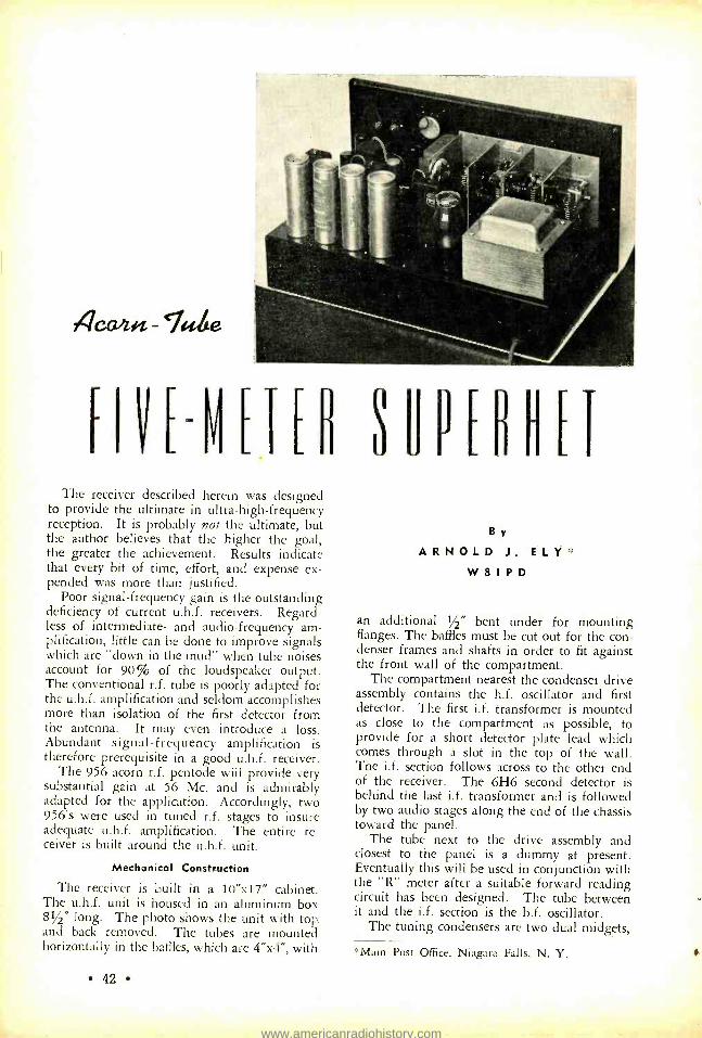
F
4ca,z>« - `Iube
HVEV[TEH UPERHET The receiver described herein was designed
to provide the ultimate in ultra -high - frequency reception. It is probably not the ultimate, but the author believes that the higher the goal, the greater the achievement. Results indicate that every bit of time, effort, and expense ex- pended was more than justified.
Poor signal -frequency gain is the outstanding deficiency of current u.h.f. receivers. Regard- less of intermediate- and audio- frequency am- plification, little can be done to improve signals which are "down in the mud" when tube noises account for 90% of the loudspeaker output. The conventional r.f. tube is poorly adapted for the u.h.f. amplification and seldom accomplishes more than isolation of the first detector from the antenna. It may even introduce a loss. Abundant signal- frequency amplification is therefore prerequisite in a good u.h.f. receiver.
The 956 acorn r.f. pentode will provide very substantial gain at 56 Mc. and is admirably adapted for the application. Accordingly, two 956's were used in tuned r.f. stages to insure adequate u.h.f. amplification. The entire re- ceiver is built around the u.h.f. unit.
Mechanical Construction
The receiver is built in a 10 "x17" cabinet. The u.h.f. unit is housed in an aluminum box 81/2" long. The photo shows the unit with top . and back removed. The tubes are mounted horizontally in the baffles, which are 4 "x4 ", with
42
By ARNOLD J. ELY "
W 8 I P D
an additional 1/2" bent under for mounting flanges. The baffles must be cut out for the con- denser frames and shafts in order to fit against the front wall of the compartment.
The compartment nearest the condenser drive assembly contains the h.f. oscillator and first detector. The first i.f. transformer is mounted as close to the compartment as possible, to provide for a short detector plate lead which comes through a slot in the top of the wall. The i.f. section follows across to the other end of the receiver. The 6H6 second detector is behind the last i.f. transformer and is followed by two audio stages along the end of the chassis toward the panel.
The tube next to the drive assembly and closest to the panel is a dummy at present. Eventually this will be used in conjunction with the "R" meter after a suitable forward reading circuit has been designed. The tube between it and the i.f. section is the b.f. oscillator.
The tuning condensers are two dual midgets,
*Main Post Office, Niagara Falls, N. Y.
www.americanradiohistory.com

956 Cs 956 C,o 954 T, 6K7 Tz 6K7 T3 6H6
Ci -25 -µµfd. midget con- denser
2-3 -30 -µµfd. mica trim- mer
G;, C1-.01-pfd. midget mica
C; -3 -30 -µµfd. mica trim- mer
C, -25 -µµfd. midget con- denser
C; -3 -30 -µµfd. mica trim- mer
C., C9 -.01 -µfd. midget mica
Cio -3 -30 -µµfd, mica trimmer
C;1- .0001 -µfd. midget mica
C12-25 -µµfd. midget con- denser
C13 -3 -30 -µµfd. mica trimmer
C11, C1;, .01 -µfd. midget mica
Cil;, C17 -.05 - pfd. 400 - volt tubular
C1,. -0.1 -µfd. 400 -volt tu- bular
C111, C20, C21 -.05 -µfd. 400 -volt
C22 -0.1 -µfd. 400 -volt tu- bular
C211, C21 -.05 -µfd. 400 - volt tubular
COMPLETE WIRING DIAGRAM
C25-.0005 µfd. midget mica
C2,- B.f.o. coupling (see text)
C27 -.25 -µtd. 400 -volt tu- bular
C2. -8 -10 -pfd. 50-450 - volt elect.
C2,-0.1-pfd. 400 -volt tu- bular
C; ;0, C; ;;, C3:; --8 -µfd. 450 - volt elect.
C;;;; -.0005 - pfd. midge t mica
C34 -25 -µµfd. midget con- denser
C;;,- ,,- 3- 30- µµfd.mica trim- mer
C:;1- .0001 -µfd. midget mica
C:;; -.0005 - pfd. midget mica
G;,. -B. f.o. tuning (see text,
C3,-.01-pfd. midget mica C10-10-pfd. 2 5 -volt tu-
bular C11 -1.0 -µfd. 400 -volt tu-
bular Ca. -.05 -µfd. 400 -volt tu-
bular C1; -.05 -µfd. 400 -volt tu-
bular C11-.01-pfd. 400 -volt tu-
bular
C1;,-10-pfd. 25 -volt elect. C46- .0001 -pfd. midget
mica R1 -1500 ohms, 1 watt R2- 100,000 ohms, 1 watt R;;- 10,000 ohms, 1 watt R.; -1500 ohms, 1 watt R;,- 10,000 -ohm potentio-
meter R1,- 100,000 ohms, 1 watt R7- 10,000 ohms, 1 watt R,. -2000 ohms, 1 watt R.- 500,000 ohms, 1 watt R10- 15,000 ohms, 1 watt R;1- 100,000 ohms, 1 watt R12-500 ohms, 1 watt R;;- 100,000 ohms, 1 watt R1.1- 10,000 ohms, 1 watt Ri:,-100,000 ohms, 1 watt R11 -500 ohms, 1 watt R10- 100,000 ohms, 1 watt R;.- 10,000 ohms, 1 watt R11,- 50,000 ohms, 1 watt R20-500,000 ohms, 1 watt R3;- 50,000 -ohm poten-
tiometer R22--1000 - ohm potentio-
meter R2;;- 100,000 ohms, 1 watt R21 -2000 ohms, 1 watt R 15,000 -ohm poten-
tiometer R21,-1.0 megohm, 1 watt R2, -500 ohms, 10 watts
R 0- 30,000 ohms, 10 watts
R2,- 50,000 ohms, 1/2 watt R30-15,000 ohms, 1 watt R;;;- 100,000 ohms, 1 watt R;; 2- 50,000 ohms, 1/2 watt R:;:- 50,000 ohms, 1 watt R31- 20,000 ohms, 1 watt R;;1- 200,000 ohms, 1 watt R;;,- 250,000 -ohm poten-
tiometer R;;; -2000 ohms, 1 watt Ro.- 100,000 ohms, 1 watt R:;.,- 500,000 ohms, 1/2
watt R;,,- 10,000 ohms, 1 watt R 11-1 .0-megohm pote n-
tiometer R12 -400 ohms, 10 watts R13-1.0 megohm, 1/2 watt Coils -See text T1, 1.2, T;; -See text T1 -6F6 output to voice
coil T5-750 c.t., 80 ma.; 6.3
v., 3 a.; 5 v., 2 amps. Si-Noise silencer switch S2- A.v.c. on -off switch S;;- Communications switch S1 -A.c. line switch 51, -B. f. oscillator on - off
switch M-0 -1 d.c. milliammeter CH;, CH2-20-hy. 75 -ma.
chokes
43
www.americanradiohistory.com

The 56 -Mc. oscillator used in aligning the receiver.
25 ppfd. per section, with isolantite supports. The particular ones used were chosen because their construction was best adapted to the layout and space, which was intentionally limited to make short leads possible. The tuning range covers considerable territory on either side of the 56 -Mc. band. If desired, several plates may easily be removed to decrease the tuning range, but in any case the maximum capacity per sec- tion should not be reduced below 15 Nfld.
The condensers are mounted on the front wall of the compartment at the proper height to couple to the drive assembly. A piece of 5/16" square brass 81/2" long was screwed to the chassis and the wall bolted to it, providing a very substantial support for the condenser gang.
It is suggested that the baffle mounting screws be tapped into the flanges and inserted from below the chassis since the parts on the baffles make the screw holes inaccessible from above. The rear wall is fastened to the chassis by two angles and the top is fastened by angles on the front and rear walls.
Acorn Sockets
Originally, metal sockets with built -in by- passes were used. It later developed that in several cases the clips shorted to the metal plates, causing no end of trouble which was exceedingly difficult to locate. So these sockets were discarded. The oscillator socket is iso- lantite, but the r.f. and first -detector sockets are bakelite, homemade with the clips furnished with the acorn tubes. It probably would have
44
been advisable to have made the sockets from victron or some other insulating material that would be better than bakelite at u.h.f. How- ever, no serious losses are introduced by the bakelite as the grid and plate leads of the pen- todes are in the ends of the envelope and do not come into contact with the socket. The sockets are very easily constructed from dimen- sions and angles given on the technical data sheets. The clips were mounted on the bakelite base by means of the small self -tapping screws furnished with Crowe name plates. They turn very nicely into no. 45 drill holes.
The baffles are from 21/e" to 23/e" apart. The spacing is dictated by the distance between con- densers and the convenience with which the baffles may be made to fit into the proper positions. Due to close spacing between baffles, it is necessary to stagger the elevation of alter- nate tubes above the chassis.
After mounting the sockets, a brass screw was run through each baffle at as central a point as possible to provide a common ground for all leads, by- passes, and a grid return from the opposite side. All leads were left about five inches long, cabled, and anchored to the baffle by cable clamps. When mounting the baffle, the cable is run through a hole in the chassis close to the flange and the leads are soldered to terminal strips underneath. Individual baffles are therefore easily removable for alterations. By- passes, cathode resistors, and grid leaks were mounted on the sockets, but voltage- dropping resistors and decoupling networks were mount- ed on terminal strips underneath the chassis, thereby facilitating voltage adjustments. A separate ground lead is included in the cable for each baffle.
The coupling and padding condensers are all 35 -ppfd. isolantite- mounted compression - type trimmers. These are supported on their leads which are of no. 14 bare copper wire and which should be made as short as possible.
The top of the compartment is provided with holes directly above each padding and coupling condenser, permitting adjustment with the en- tire unit assembled.
Coils
1.1, the antenna coil, consists of 6 turns of no. 14 bare copper wire, 11/16" long and 1 /2- inch in diameter. L2i L3, L4 and L3, the tun- ing inductances for the r.f. stage and the os- cillator, consist of 8 turns, same wire and diam- eter, 1 inch long. L5 is tapped two turns from ground for the cathode tap of the 955 h.f.
www.americanradiohistory.com

oscillator. These coils are mounted directly on the tuning condensers, the leads should be as short as possible, and the coils should be placed as near as possible to the center of their respective compartments.
The r.f. chokes were commercially made, but homemade ones for this frequency should per- form equally satisfactorily.
If each baffle is wired and mounted with its associated inductance, starting with the one next to the drive assembly, no difficulty should be experienced in assembling the high fre- quency unit.
I.F., Second Detector, A.V.C.
T1, T2, and T3 are 3000 -kc. iron -core i.f. transformers. The i.f. section is conventional and feeds into one diode of the 6H6 second detector, which also provides a.v.c. to the intermediate amplifier. The "R" meter is in the plate circuit of the i.f. amplifier and is actuated by changes in the plate current due to signal- variation of the a.v.c. It is backward reading and it is suggested that it be mounted upside down to indicate increased signal as the pointer moves from left to right. Or, a for- ward reading "R" meter as suggested by Higgy
RADIO, Oct., 1937) might be substituted.
Noise Silencing
The other 6H6 diode acts as a noise limiter in a modification of the Watzel circuit. Two systems were tried, the one shown proving to be superior. It does not entirely eliminate ignition interference but the silencer does re- duce it to a level which more than justifies its inclusion. Silencer operating voltage is secured by the drop in the 500 -ohm resistor between the power transformer center tap and ground. This voltage is varied by the 50,000 -ohm po- tentiometer which shunts the resistor. The control is mounted beneath the "R" meter on the panel and the on -off switch for it is a part of the control.
High- Frequency Oscillator
The high -frequency oscillator is of the grounded -plate Hartley type. Both grid and cathode coupling were tried. A slight amount of instability was experienced with grid cou- pling and inasmuch as cathode coupling cor- rected this fault and was otherwise quite satis- factory, the choice was inevitable. The cathode tap was made two turns above ground. The tap position does not seem to be too critical, but it may be necessary to vary it to obtain peak performance.
Under -chassis view. It will be noted that four filter chokes are employed whereas only two are shown in the wiring diagram. These were required because the local line supply was 25 cycles; they will not be needed under ordinary conditions.
Beat -Frequency Oscillator
L6 is the b.f.o. coil. It consists of 11/4 inches of no. 30 enameled wire on a 1/2 -inch wooden dowel, tapped 1/4 inch from ground. This unit was made from the parts of a broadcast i.f. transformer. The compression -type tuning con- denser, grid -coupling condenser, and grid leak were mounted inside the can, which was wrinkle finished to match the i.f. transformers. Coupling to the detector input diode was through the small capacity of one turn of in- sulated wire around the diode lead. Coupling should be varied until it is possible to hetero- dyne signals of various levels satisfactorily. Since taking the photograph, it was found necessary to shield the b.f.o. grid lead and to place a metal cap over the tube, as its output was getting into the i.f. section through the i.f. grid leads.
T4 is a universal output transformer which will couple to any voice coil. A permanent - magnet dynamic speaker was used in our case. The transformer is mounted underneath the chassis.
It will be noted that every stage is decou- pled by a 10,000- or 15,000 -ohm resistor. This may or may not be necessary in all cases. The power transformer supplied more voltage than was required and the excess was utilized in decoupling and providing noise -silencer oper- ating voltage.
Although a front -panel view is not shown, the panel controls are, from left to right: r.f. gain control and primary switch, i.f. gain, a.f. gain, tone control, stand -by switch, a.v.c. switch,
(Continued on Page 77)
45
www.americanradiohistory.com

56 Mc. 2z Rain paid!
By E. H. CONKLI N *
This is W4EDD in Coral Gables, Florida, perhaps more widely known on 28 -Mc. phone. The 56 -Mc.
receivers do not appear in the photo.
All districts participated in the five -meter dx in May! Two stations have already worked seven districts. To mention some of the high spots, W6's worked W7's on the 12th; W4EDD worked all northeastern districts on the 15th ;
W5EHM made 28 contacts with W3 -W8 -W9 on the 19th; W9's worked W2 and W3 sta- tions on the 27th; W5EHM raised gobs of W8 and W9 stations on May 30, 31, and June 1. By the end of the month, everybody seemed to be working everybody else. We have tried to collect both sides of the story for the earlier days in May and at least some of the news for the later ones.
May 12
The first day on which numerous contacts were made, as far as has been reported to us, was May 12. Some of this story was carried last month in Herb Becker's dx department. Eldred W. Start, W7AQJ, of Vancouver, Wash., said that the first symptom was short skip on ten meters after 5 p.m. Pacific time, sixth dis- trict stations coming through with very good signal strength, so he switched to 56 Mc. at six o'clock. In ten minutes the first contact was made with W6I0J in Hollywood whose i.c.w. was a steady R7 to 8. Next he was called by W6MKS in San Diego who got W6DNS in on a three -way, phone and i.c.w., until 6:38. He was then being called by W6AVR in Colton,
*Associate Editor, RADIO.
46
Calif., whose phone was fading from R9 to 7. At 6:55 W6IOJ was again raised.
During this time, W7ABZ, W7FQV and W7AKY of Portland had come on the air when the sixth district seemed to be fading out. Five minutes later the signals were back and W7AQJ spent nearly an hour getting the Portland gang back on the air. W7ERA joined in on the dx. W7AJQ had another contact with W6AVR at 8:15, finding the signals still strong both ways. W6I0J had in the meantime worked W7ABZ but could not raise the others. Contacts con- tinued between the W6's and W7's who were on the air, until 9:15 when things were inter- rupted in Portland by a call from a K7AMM who doesn't seem to be licensed. At 9:20, W6GZE in San Francisco called W7AQJ with an R7 to 8 signal. W6AVR confirmed the Portland observation that the band had been fading out in cycles of approximately thirty minutes with a complete recovery each time. W7AQJ heard W6HDY, W6KFE and W6VQ, receiving cards from W6MQQ and W6OJU.
Start says that he used a three -tube super - regenerative receiver with type 76 tubes, built six years ago. The transmitter uses a self - excited pair of 45's with 20 watts input, mod- ulated by a single 45. The receiving antenna was a horizontal wire, while the transmitting antenna was a half -wave doublet with a para- sitic reflector aimed roughly southwest.
The ultra- high- frequency end of station W2JCY in North Pelham, N. Y. 250 -watt and 1- kilowatt transmitters can be seen in the background. Reading from left to right are Lt. W. A. Freeman, W8NR; RM1C Merritt
Kirchoff; Lt. Commander L. M. Cockaday, W2JCY.
www.americanradiohistory.com

All districts participate in five -meter dx in May! Two stations work seven districts. By the end of the month, everyone seems
to have been working everyone else.
May 15
The honors for Sunday, May 15, go to H. H. Robinson, W4EDD, of Coral Gables, Fla. Robbie worked W5EHM crossband last year, and made definite plans for dx attempts this summer. He put up a 5- element Yagi array "a la W2BMK" with three directors and one reflector all spaced 1/4 wavelength, the antenna fed with a concentric line, and tested several receivers. Larry Cockaday, W2JCY, and Frank Lester, W2AMJ, kept after him to start the schedule. Because Frank was going to pull down his equipment shortly, a test was ar- ranged for 1 p.m. Eastern time Sunday, May 15, with fifteen -minute transmitting and listen- ing periods. This was confirmed on 28 -Mc. phone after W1KNM and W2HWX passed the details on to the first and third districts.
At one o'clock Eastern time nothing was heard, but at 1:15 in came W4EDD giving a list of stations heard in the preceding 15 min- utes. It was apparent that somebody had his clock or the schedule wrong, but there would have been bedlam anyway. W2JCY says that a hundred stations could be heard calling W4EDD during the transmitting periods, while Robbie found the band so wide open and so many stations calling that QRM was terrific. Using a resistance -coupled -i.f. superheterodyne, Robbie could only take the loudest stations. He remarked that sharp i.f. stages, even if only the stabilized stations could be copied, were neces- sary with interference like that.
During the listening periods the following were logged at W4EDD with R6 or louder signals: W1IXP, New London, Conn.; W2ISY, Bogota, N. J.; W2GZC, New York City; W3GMZ, Washington, D. C.; W3EZM, Lang- horne, Pa.; W3GGC, Philadelphia; W2AMJ, Bergenfield, N. J.; W3CMA (incorrect call - not issued) ; W3FOM (not on air; incorrect call) ; W3HKN, Washington, and W3GOK (not on 56 Mc.; incorrect call).
Robbie stuck to the schedule though plenty of the boys worried for fear that the band would close down before contacts were made. W2JCY on 58 Mc., with 250 -watts crystal controlled, told W4EDD that he won the Stetson hat for the first QSO with that district -there remaining only two such offers for the first W6 and W7 stations to work W2JCY, the only remaining unworked districts!
Robbie told Larry about his R9 signals, but completed a series of about five transmissions with W2CUZ testing antennas. Robbie found no difference between horizontal and vertical polarization, but W2CUZ thought that a hori- zontal flat -top gave somewhat better signals and less fading than a vertical "J". W2JCY was next worked. Some of his log reads as follows:
"(W4EDD finishing with W2CUZ) 'Well, this is fine. I want to have a complete two -way QSO with Larry; I think he owes me a brand new Stetson hat! Larry's signal is tremendous here. Well, so long, Den, this has been fine and I hope we can do it again. I'm going over to Larry now. W2JCY, this is W4EDD listening for you now Larry. Come in.'
"W2JCY called W4EDD but could not log what was said. Three transmissions. W4EDD answered as follows: 'W2JCY, W4EDD Coral Gables calling and coming back. O.K., Larry, this is certainly fine and better than ten meters. Little did I think when I talked to you on "ten" this morning making the final arrangements that it was going to be this good. I'm never going back to ten! This is fine. I heard you repeating over and over about the tele- gram and report. . . I have never been so pleased. Boy, am I pleased. When I first heard you, you were R7 but you have been R9 plus with some QSB
The receiving position at W2ISY.
47
www.americanradiohistory.com

W2ISY's Mobile Rig.
but all O.K. Yes, I heard Frank (W2AMJ). I will be glad to listen for him. Go ahead, Larry.'
"W2JCY thanked W4EDD for the test and wanted to sign to give the others a chance. W4EDD an- swered again: 'O.K., Larry. I am glad you have all the transmissions logged. You were on the loud- speaker all the time; could hear you all over the building. Will sign with you now and listen for Frank. Good luck. Will write you tomorrow and will send all stations heard QSL cards. So long, Larry, will see you later.'
"W4EDD contacted W2AMJ at 2:25 Eastern time. At 2:40, he contacted W8CIR in Pittsburgh then W8NED, very short, saying, 'W8NED, you came in O.K. but faded out.' W2CUZ called W4EDD again and tested with him, W4EDD answer- ing, 'Please g_t a message to Frank and tell him that the receiving was done on his Lafayette acorn re- ceiver. I have 150 -watts input into antenna, same type as I use on ten meters. All signals come in just the same with either vertical or a horizontal antenna. My antenna is 30 feet above a two -story building.' W2CUZ made a very long transmission testing on a vertical antenna and on a horizontal beam. W4EDD could hear both about the same; this not logged carefully because of interest in re- sults; could not notice much difference on either a vertical or a horizontal except that when one was best, the other was weakest, in pick -up. The re- sults indicate that this was a real reflection because if it were not, the receiving station would have to use the same polarization as the transmitter to get the best reception.
"At 3:10 there was QRM on W4EDD after which he said, 'It sure doesn't seem to make much differ- ence how much power you fellows use; one of the stations I heard was using only 30 watts. Power doesn't seem to mean much. I will now listen for W1EYM so you can sign off. 73.'
"W4EDD then called W1EYM but didn't QSO until W2JCY called and said he was on 56.64 Mc.
48
after which W4EDD thanked W2JCY for the fre- quency and came back to W1EYM as follows: 'W4EDD coming back to W1EYM. O.K. and R6. Some of those second district stations are putting in terrific signals here and causing me QRM. This is my farthest dx on five meters so far today.'
"Meanwhile, at least a hundred New York sta- tions were calling W4EDD wildly. W4EDD con- tinued, 'W4EDD calling W2ISY. I heard you call- ing me but QRM is terrific now. You were R8 to 9. I hope that I am doing as good.' W2ISY didn't come back until W2JCY relayed the call. W4EDD continued: 'W4EDD calling W2ISY. I heard your first call and answered you but did not hear you come back. So long, O.M. I also heard W2BHD. What say, W2BHD ?'
"Following QRM, W4EDD was heard to say: 'Not very strong here now. I've heard about 30 to 35 stations but too much QRM now. I was trying to get W1EYM through. I got a report from him. I'm trying to do the best I can to answer all the boys I hear calling me. I will turn it back to you. I
appreciate this contact on five meters. W4EDD off to W2BHD : W4EDD back for a final with W2BHD. Will send you my QSL card. Sorry that I could not work everybody. 73 and best of dx.' W4EDD then gave a few more calls but began to fade very rapidly until 3:58 when his voice was too weak and we switched on the beat -frequency oscil- lator. His heterodyne ceased at 4:08, standard time."
The whole rig at W9CQV in Chicago, who worked W5EHM on the 19th. In the center is the T20 long line oscillator, with the superregenerative receiver on the right. Before this, the W8CVQ
card was the proud dx.
Frank Lester, W2AMJ, said that gloom was heavy because of the lack of success with W9 tests after dx in previous years. May 15 was a rainy day, as it was in Florida, keeping many of the fellows home. On tuning his receiver, Frank heard a voice like Robbie's, but passed it up until he heard the list of stations received and knew it to be the test transmission. The signals were hitting R9 plus on peaks on the
www.americanradiohistory.com

R meter in his SX17 receiver, which was being used in conjunction with a tuned 954 r.f. stage plus a little fixed regeneration. As at W2JCY, the signals faded out around 4:08 but they last- ed until around 4:30 at W1EYM and in Ohio.
W2HWX made his contact with W4EDD at about 2:15. His present transmitter is a
band -switch job for 14, 28 and 56 Mc., com- pletely enclosed in a 42 -inch par -metal cabinet with speech amplifier and all power supplies. The final uses a pair of 35T's with 400 -watts input. The receiver is an Ultraskyrider with a two -stage preselector using 956 acorn tubes on 56 Mc. only. The antenna is four -in -phase arrangement in a diamond shape, with five re- flectors, motor driven.
W3GMZ in Washington received a confir- mation for 1:15 to 1:30, but he heard two complete transmissions and copied the key numbers C -155 and C -156. The transmitter is crystal controlled on 57,240 kc. with 135 watts on a pair of T55's in the final. The antenna is a Q -fed horizontal. A resistance coupled i.f. superheterodyne is used.
Up near Pittsburgh, W8CIR has been doing a lot of good dx work. He heard W4EDD from about 2 to 5 p.m. on the 15th using a seven -tube superheterodyne. His transmitter, with 250 watts on 56,130 kc., puts one of the best eighth district signals into Florida, with the help of a Yagi array only 20 feet high, using three directors and three reflectors. This generally gets 2 to 5 R's better reports than a Q -fed dipole 80 feet high.
W8NED in Pittsburgh was another of the stations able to work W4EDD. He said that almost everyone heard Robbie, even one sta- tion located in a narrow valley which has diffi- culty working locally. W4EDD came through
Frank C. South, W3AIR, Princeton, N. J.
X
W1KTV, the station of George Newick in Ports- mouth, New Hampshire.
from 2 to 4:15 while at 2:50 a W5 also was heard, very weak but not identified.
Up in Connecticut, W1EYM heard Robbie promptly at 1:15 on schedule, R9 plus, corn- ing in best on a Q -fed vertical 60 feet high - but when he faded down, the strength could be brought back on a horizontal 20 feet high. The receiver used a converter with a 954 r.f. stage, a 954 detector and a 955 oscillator, work- ing into a Hammarlund Super Pro. The QSO at 3:24 p.m. was made on a crystal controlled transmitter with 70 watts on a pair of 6L6's in the final, modulated with 6L6's. The only other dx that came through during the after- noon was semi -local -W3EZM and W2HWX.
W3EZM, in Langhorne, Pa., says that Rob- bie was coming through with typical 28 -Mc. fading from about 1 to 4 p.m., with almost everybody on the band also hearing him. New- bold has no less than twelve tubes in his super- heterodyne with acorn r.f., 2 -Mc. untuned 1.f., noise silencer, and all the works. The trans- mitter on 58.32 Me. has 150 watts on a pair of 808's feeding either of two 5/8- wavelength vertical antennas through a coaxial cable. The antenna is 70 feet above ground, putting it 290 feet above sea level.
About the time of the schedule, W2ISY de- cided to straighten out his antenna system, then to listen to a b.c.l. program. At 1:45 when the SX17 and single stage regenerative pre - selector were fixed up on "five ", every audible crystal controlled transmitter was calling W4EDD! When he did come through, it was so loud that Ross checked the band switch be- cause it sounded like his usual 28 -Mc. signal. The 400 -watt transmitter brought an R9 plus report when the contact was made at 3:20.
Herb Baasch, W2BHD, was one of the last to make a contact. He was using 120 watts on a pair of 35T's in the final, driven by 802's. The antenna was a 66 -foot center -fed Hertz located 25 feet above the apartment roof, and running north and south. The receiver was built originally for 40 and 20, using two 6D6 preselection stages, 6C6 detector, 6C6 second
49
www.americanradiohistory.com

The 56- and 28 -Mc. rotary beams at W5ALK in Fort Worth, Texas.
harmonic oscillator, two stages of 500 -kc. i.f., 6B7 second detector and 42 audio. The regen- eration in the first r.f. stafze accounts for a lot of the gain.
Other Dx Reports
Within ten days, W4EDD had received some 125 cards from various points from Connecti- cut to Ohio. Most of those whose signals got into Florida were also hearing Robbie. W8KG/ W8YC in Akron listened to most of the QSO's but didn't make contact. W8MST in Arnold, Pa., some eighteen miles north of Pittsburgh, followed most of the work, using a four -tube resistance coupled superheterodyne and a ver- tical J antenna, concentric line fed. W8RSS heard an unidentified W2 but didn't hear W4EDD although other Cincinnati stations heard and worked him. W9WLX in Ft. Thomas, Ky., is another greater Cincinnati station reporting W4EDD. W8PTG in Springfield, Ohio, heard W4EDD weak and fading at 2:50 during the contact with W8NED, although another listener there had reported Robbie R9 a little earlier. W2GZC heard the dx only for about two minutes at two o'clock.
W8VO in Akron heard W4EDD all after- noon, W5EHM around 1:00 p.m., and W2EHV around 4:00 p.m. W8KAY also heard W4EDD. Several stations around Cuya- hoga Falls, Ohio, heard him.
W2KXH at West Orange, N. J., advised his wife not to waste her time listening for the test transmissions. Soon, she let out a shriek when she heard the transmissions start.
In Dallas, W5EHM heard weak carriers from
50
3 to 7:45 Eastern time, then a harmonic from W4EEV in Atlanta. The latter uses a kilo- watt on 28 Mc. and has since put R9 signals into Dallas on "five ".
W4EDD's Rig
The transmitter at W4EDD uses a pair of 809's (what, that little tube ?) with 150 to 175 watts input. The horizontal Yagi antenna has already been described. The receiver was a six -tube superheterodyne with resistance - coupled i.f. stages. Sharper receiver selectivity, even if unstable signals will be sacrificed, will be absolutely necessary for this type of dx when hundreds of signals come through at once. An RME 510X expander has already been re- ceived, allowing a selective receiver to be used in a triple -detection arrangement.
May 19
Up in Milwaukee, W9ANA has been run- ning an automatically keyed 500 -cycle r.a.c. rig on 56,936 kc., with 250 watts on a pair of 50T's in the final, driven by T20's. At 8:16 a.m. Central time on May 19, he was heard by W5ALK in Fort Worth, Texas. At 10:08 a.m., W1KTV in Portsmouth, N. H., logged him for about ten minutes. During the Radio Club meeting that night, W5EHM also heard him. At 1:45 p.m., Eastern time, W8CVQ heard two dx stations on 58 and 59 Mc. send- ing five letter and number code groups to each other, but they faded out.
While there was a lot of dx work done dur- ing the evening, the most remarkable was that of J. C. Patterson, W5EHM, of Dallas who put his contest experience to work and smooth- ly went through twenty -eight QSO's in an hour and forty minutes, some as close together as one minute. He had enough time to test receivers and antennas, and to check the 28- Mc. band to find that it was open in the same direction at the same distance. Between 6:50 and 8:30 p.m. Central time, he made the fol- lowing contacts, almost the entire list having been confirmed to us directly: W8OQJ, W8RSS, W8PEJ, W8KG, W8EUK, W3GMZ, W8KAY, W9CLH, W8JMS, W8QDU, W8CIR, W8YUT, W9WLX, W9CQV, W9FP, W9YFQ, W9AAV, W9TZQ, W9OCW (also reported as W9OPW on May 27), W9VJO, W9SQE, W9ARN, W9ZGD, W9ZEO, W8PNU.
His earlier list also mentioned working W9MPV in Milwaukee (W9ANA confirms this contact) and W8FMI (who moved from
www.americanradiohistory.com

his Cincinnati address), these calls being over- heard by W9TZQ. Calls heard included W3GOD (incorrect call or a bootlegger with an ego), W8NSS and W9ANA.
The first QSO was with W8OQJ in Cuya- hoga Falls, Ohio, at 6:50 p.m. Central time, who said that W5EHM was heard until 8:15 p.m. The receiver is a resistance -coupled su- perheterodyne, the transmitter crystal controlled with 20 watts on a single 6L6 final. The an- tenna is a vertical doublet some 30 feet high.
In Cincinnati, W8RSS was working a weak local when he was interrupted by someone fading in calling "CQ DX ". In some disgust, W8RSS waited for the sign which gave him a terrific jolt when it was W5EHM. This was at 7:10 p.m. Central time, the signal lasting until 8:50. Two or three other fifth district stations were also heard but their calls were not definitely logged. W8RSS runs about 60 watts crystal control, using a vertical antenna 35 feet high. The receiver is the usual for the Cincinnati area, a resistance -coupled super- heterodyne.
Next was W8PEJ in Ingomar, Pa., about ten miles north of Pittsburgh. He had been hear- ing Pat since 6:55 Central time, working him at 7:05 and listening until he passed out at 8:15. During this time a W4 was heard but fast fade and storm static prevented identifi- cation. A single 6L6 with 30 watts input, resistance coupled superheterodyne, and a Q- ted vertical 40 feet high, were used.
In Akron, W8KG /W8YC heard Pat from to 8:20 Central time, working him at 7:15.
W5E? (possibly W5EEX in Houston) on 56.5 Mc. was heard in the QRM. Several other weak stations were also coming through. The transmitter was a single 6L6 final with only 11.5 watts input to the plate and screen, get- ting an R7 to 8 report! The receiver was an SX16 Superskyrider with the r.f. stage cut out by connecting the antenna to the 1st detector grid. On 56 Mc., this has doubled or tripled the signal strength in the several sets on which it was tried.
Pat went right after W3GMZ in Washing- ton, D. C. W5EHM was R4 to 9, slow fad- ing, often louder than many locals. W3GMZ's rig was described under the Florida dx of May 15.
After providing a good dx signal last year, W9CLH has heard some of the dx, and worked W5EHM twice on the 19th, as well as W5EEX in Houston at 8:30 Central time. The crystal controlled rig at W9CLH puts about a half
kilowatt on a pair of HK354's using a short condenser -tuned line running above the rack, as a tank circuit; this rig usually brings an R9 report from the dx ! The antenna now is a vertical four -section flat -top pointed east or a little north of east, for working Chicago and W8CVQ. Both an Ultraskyrider and an RME with the 510X expander are used for receiving.
On the 19th, W8QDU drove out to a hill near Pontiac to try for W8CVQ with a mobile rig. He heard W5EHM making a few con- tacts and dragged down a QSO for himself. The signals lasted until 8:20 Central time, fading all the while. An acorn superregener- ative receiver was used, being interferred with by static discharges. Detroit stations faded down until W5EHM had gone out for some twenty minutes. W8QDU mobile uses 15 watts into a crystal controlled RK34 on 56,016 kc., feeding a 3/4 -wave vertical through a con- centric line. At the home location, 250 to 350 watts on a pair of 35T's on 56,060 and 57,030 are used, the receiver there being a re- vamped Ultraskyrider with a two -stage acorn - tube preselector.
WBCIR didn't miss this dx either. He worked W5EHM with R9 signals both wags using the 80 -foot -high vertical, and R14, ac- cording to W5EHM's R meter, using the Yagi!
[Continued on Page 78]
Mox Fisher, W5ALK, who heard plenty of the dx going on May 19th.
51
www.americanradiohistory.com

THEHVHNEH
is he Zt/o4a2
B y
F R A N K F R I M E R M A N,
W 2 F Z
When George Korper, Jr., W2HMD, finally decided to forego single blessedness, Mrs. Korper, Junior, succeeded where for many years Mrs. Korper, Senior, had lamentably failed. "This radio junk," the interdict read, "must be Gone With the Wind, and so forth; in plain English, either hide it or put it out!"
So we hid it. While not a new one, the problem of how to reconcile the ham station with the interior décor of a Manhattan cliff - dwelling has been solved here with particular elegance, so we think. The physical space avail- able consisted solely of a mahogany "secretary ", outside dimensions 47 "x341/2 "x14 ", inside di- mensions slightly less. Into about half a cubic yard of volume it was desired to stow away a medium -powered phone rig complete with modulator, power supplies, superhet receiver, space for log -book, extra coils, etc., and, as a concession to the lady of the house, a phono- graph to work through the speech amplifier of the modulator for domestic use. Further- more, with the front doors closed, it had to look as innocent as milady's escritoire, which indeed it was.
The results, while not very startling from the point of view of radio theory, merit the attention of amateurs who appreciate a neat piece of design. Working at such close quar- ters, the utmost care had to be taken in the allocation of space to the various units, while at the same time preserving the goals of accessi- bility, safety, and flexibility of control.
The upper third of the secretary was covered by a horizontally swinging door which formed the writing desk when lowered. Behind this a clear space was made by removing miscel- laneous partitions and cubby holes. In the
52
lower right -hand corner of this space was mounted the communications superhet receiver. To the left of the receiver we placed the r.f. end of the transmitter. Directly above it, the speech amplifier and control panel were mounted. All the chassis and panels are of 1 /8" thick aluminum. They were first cut and drilled, then sent out to be engraved and gray crackle sprayed.
The bottom two -thirds of the secretary con- sisted of a tier of three drawers 18" wide, 7" high, and 12" deep. The top drawer was re- served for odds and ends, the middle drawer received the class -B modulator and power sup- ply, while the phono turntable and pick -up were put in the bottom drawer. There remained a volume 21 "x13 "x12 ", covered by a vertically swinging door. The open space was fronted with a piece of matching wood and divided into two sections, the top one containing a ten -inch PM dynamic speaker and the receiver "B" supply, the bottom the main 300 -watt power supply for the transmitter final.
R. F. Lineup
The r.f. end of the transmitter was simpli- fied considerably by W2HMD's operating hab- its. Since he works exclusively on 10 and 20, band- switching by means of the shorted - turns method proved compact and practicable. The oscillator is a 6L6G, an 807 functions as buffer- doubler, and the final uses one of the new 50 -watt beam tetrodes with about 1250 volts on its plate. The oscillator is controlled by any of eight 20 -meter crystals, selected by
www.americanradiohistory.com

CHASSIS A
DRIVER STAGES WITH POWER SUPPLY
P C 6L6G 807
ro CHASSIS B To CHASSIS 10 2 + 3
MONITOR BUZZER
53
KEYING RELAY
c---11 II
A C B D
C17
C1- .0001 -µfd, mica C_ .0005 -µfd. mica C:1- .001 -µfd. mica C4-1 5-14.0d. midget
riable C5-.0001-0d. mica CI -.005 -µfd. mica C; -25 -14µfd. midget
rioble C,0- .002 -µfd. mica CSI -.001 -pfd. mica C,,,- .005 -µfd. mica C11 -30 -µµfd. midget
riable C12 -50 -µµfd. midget
riable
VG-
VO-
va-
va-
0 0 0
a-
vo-
va-
va-
000 T,
C1:1- .001 -µfd. mica C1.1 -0.5 -µfd. 600 -volt tu-
bular C15-0.1 - ¡ltd. 400 -volt tu-
bular Cif,-.002-pfd. mica C1;, C10, C19- .005 -µfd.
mica C_II, CD, -8 -0d. 450 -volt
electrolytics R,- 50,000 ohms, 1 watt R_ -10 ohms, 10 watts R:1 -400 ohms, 10 watts R1-10,000 ohms, 10 watts R,-, -100 ohms, 10 watts RI -10 ohms, 10 watts
R; -5000 ohms, 10 watts R,,-40 ohms, 10 watts 1,I -1000 ohms, 40 watts Rill- 15,000 ohms, 25
watts RFC- 21 /2 -mh. 125 -ma. r.f.
chokes L1 -12 turns no. 18 d.s.c.,
11/4" dia., spaced to 1" L -11 turns no. 18 d.s.c.,
11/4" dia., spaced to 1" and tapped 31/2 turns from gnd. end
CH1- 30 -hy. 50 -ma. filter choke
CH2-5 -hy. 150 -ma. swing choke
CH:,- 15 -hy. 150 -ma. fil- ter choke
T,-6.3 -volt 3-amp. fil. trans.
T2-5 -volt 2 -amp. fil. trans.
T:1 -900 v. c.t., 150 -ma. power trans.
S1- Crystal selector switch SD-Two-circuit bandswitch S3- Buzzer on -off switch Si-Meter switch SD -Plate on -off switch M -0 -100 d.c. m i l l i a m-
meter P -6.3 -volt pilot lamp F- 250 -ma. fuse
means of a front panel switch. This means a choice of eight crystal -controlled frequencies on either band. To save space, the crystals are mounted turret -wise on a dress -up coil can.
The transmitter is mounted on two similar chassis, 9 "x12 "x3 ". These are mounted one above the other on a panel 15%4 "x133/4 ". The lower one, chassis A, has the driver stages, while the upper one, chassis B, bears the final. Chassis A also contains power supply for the driver.
Capacitative coupling between stages is used only because of lack of room. Link or straight inductive coupling is much to be preferred. We have found that the coupling condenser's value is fairly critical, and this has necessitated the use of small variables in this position. Other- wise the troubles have been surprisingly few. The base and input section of the final have been shielded, and no feed -back has been ex- perienced.
A number of refinements have been in_or-
53
www.americanradiohistory.com

Rear view of the entire unit of the "Manhattan transmitter."
Plate, grid, and screen supplies for the RK -47 final amplifier (chassis CI.
CHASSIS E
2 3 4
1
o 320
8
28
RECEIVER 3au B- SW sP:An I¡¡
31 32 4
UN 4 2
CHASSIS D \ á
IS
12 SCOPE
CHASSIS B ANTENNAS
0 0 O 0 7 10 M. 20 M.
RECEIVER 33 34 'SCOPE -0 Q O O
CHASSIS A
10
28 29 23 27
PEAKER
LINE-TO-VOICE-COIL TRANSFORMER
ECEIVER A.C. OUTLET POWER SUPPLY
3 1
DESK LIGHT AND SWITCH
CHASSIS C
24
PHONO. TURN- TABLE AND
PICKUP 26 A.C. POWER
INPUT 13 14 15
LINE CORD
Complete diagram of the interconnections of the various units.
5 4
www.americanradiohistory.com

porated here which are worthy of attention. First, the problem of metering: We have used a method which for some reason is rarely em- ployed by the amateur who, because of economy or lack of space, must use one meter to read current in two or more circuits. It is by far superior to the objectionable plug- and -jack method and even to the new special switches brought out for the purpose.
In effect, the meter shunt is left permanently in series with the circuit through which it is desired to read current, and the meter is simply connected across the shunt whenever necessary. Since the shunts are of low resistance, the loss in voltage through them is negligible. Thus, in our case, the meter shunts are left perma- nently in the cathode circuits of the 6L6G and 807 respectively. Leads a, b, c, d are brought out to a d.p.d.t. switch, with the switch arms across the milliammeter. Cathode current in- stead of plate current is therefore easily read for either tube, but this is good enough; in any case, the same system could be used in the plate circuits. Similarly, leads g, h, 1, k are brought out to a second switch and low -scale meter to read grid current of the 807 and the final. A third meter reads final plate current all the time. Had it been necessary, one meter could easily have been used for all of this, but even so a great saving is effected.
Second, a pair of relays mounted on chassis B perform some interesting functions. It will be noticed that the band switch in the 807 tank has an extra pair of contacts. Since separate
Rear 3/4 view of the transmitter showing chassis A (lower and chassis B (upper).
.33
CHASSIS B
ANTENNA SWITCHING SYSTEM AND FINAL AMPLIFIER
814 OR
RK47 TO OSCILLOSCOPE
TO RECEIVER
pAAND- SWITCH RELAY
SEND - RECEIVE RELAY
ON CHASSIS
rAN K G LN
2 4 3 FROM CHASSIS A
C1 -30 -µpfd. 3000 -volt variable C2- .005 -µfd. mica C3, C4 -.005 -µfd. mica C5- .001 -µfd. 2500 -volt mica R- 20 -ma. meter shunt RFC- 21/2-mh. 125 -ma. chokes SI-Final tank bandswitch S2 -High voltage safety switch S3- Milliammeter switch L -20 turns no. 10 enameled, 11/2" dia., spaced to 5"
and tapped 5 turns from ground M1-0-10 d.c. milliammeter M2-0 -200 d.c. milliammeter
antennas are used for each band, this pair of contacts is used to close a d.p.d.t. relay which then connects the 10 -meter antenna to the out- put. The other relay is similar, but is con- trolled by the plate switch. When this is open, the proper antenna for the band in use is
switched automatically to the receiver. At the same time, and also by means of the plate switch, a closed -circuit relay in the B- lead to the receiver is actuated. This relay is nor- mally closed, but when the transmitter plate switch is on, it opens and the receiver goes dead.
This system therefore accomplishes three de- sirable things: (1) The proper tuned antenna (i.e., the transmitting antenna) is employed by the receiver for the band in use; (2) trans- mitter noise is kept out of the receiver during transmission; (3) alI this is accomplished by the single manual operation of throwing the transmitter plate switch. It might be added
55
www.americanradiohistory.com

FINAL AMPLIFIER PLATE & SCREEN SUPPLY AND BIAS SUPPLY
CHASSIS C L
> 0 N
+
TO D
CI, C0-2 -µfd. 2000 -volt condensers C1 -8 -0d. 450 -volt electrolytics C, -1.0 -1.1fd. 400 -volt tubular R.- 30,000 ohms, 75 watts, slider type R.- 25,000 ohms, 40 watts, fixed
R;;--i5,000 ohms, 25 watts, slider type T1-2.5-volt 10- ampere filament transformer T2 -2800 volts c.t., 200 -ma. power transformer T3 -500 volts c.t., 40 ma.; 5 volts, 3 amperes S -Plate voltage on -off switch
that using the transmitting antennae for recep- tion, aside from being good for reception, saves roof -space for the apartment -dweller, who gen- erally has very little.
Since fixed bias is used on the 807 and final, it is possible to key in the cathode of the os- cillator. The keying relay has double contacts,
CHASSIS D
MODULATOR AND MODULATOR POWER SUPPLY
CH, CH2
To C To E To E
5
R4 C3
e ®® 37 9 75
TO 'SCOPE TO TO B C
one pair of which keys a buzzer, ve_y useful with a bug. A switch on the front panel cuts out the buzzer if desired.
The only thing the outfit doesn't have is a built -in oscil- loscope. It would have been there, but there simply was no place to put it where it could have been seen, not even a measly one -incher. The next best thing was to make provis- ions for an external oscilloscope,
and this was done by bringing out a pair of leads from a small pick -up coil permanently coupled to the amplifier tank.
The class -B modulator and power supply (chassis D), which can just be seen in the middle drawer, employs a pair of 809's or RK- 12's for audio and a pair of 866 jrs. for power. The chassis dimensions are 10 "x17 "x2 ". Audio excitation is supplied from the speech ampli- fier, which will be described later. The con- denser C3 and potentiometer R, provide for trapezoidal patterns on the oscilloscope, in con- junction with the r.f. pick -up coil noted above. Since the modulator is not visible, the plate milliameter had to be mounted on the speech
(Continued on Page 90)
CI- 1500 -volt 2 -1.fd. filter condenser C2- 1000 -volt 4-pfd. filter condenser C:; -.02 -µfd. 5000 -volt mica R1-25,000 ohms, 75 watts R2-10 ohms, 10 watts R3- 250 -ma. meter shunt R I -1.0- megohm potentiometer T1-6.3-volt 5 -amp. fil. trans. T3 -2.5 -volt 5 -amp. fil. trans. T3 -1700 v. c.t., 225 ma. power trans. T -Class -B input trans. T3- Class -B output: 9000 ohms p.- to -p.,
8300 secondary CH, -5 -25 by., 225 -ma. swing choke CH2-10 hy., 225 -ma. filter choke F- 250- milliampere fuse
56
www.americanradiohistory.com

Figure 1. Horrible example No. 1, the old buffer unit at W9FM. Symmetry of de- sign alone does not make
for perfect operation.
TAHURLE HHHTNH
B y E. H.
Not so very long ago -about fifteen years - most of the wire in a "wireless" transmitter was in a 25 -turn inductance. With it, we could get down to about 240 meters if the radio in- spector put enough pressure on us. A little later, a few receivers were pared down to well below 200 meters and some good contacts across the country and the Atlantic became pos- sible using considerably less than a couple of kilowatts. There followed a mad rush to re- move the bases from tubes, and otherwise to cut down on all possible losses in an attempt to get "low loss" circuits that wouldn't catch fire now and then, and actually tune down to a wavelength of nearly 100 meters.
Since those years, when the battle cry was "Spark Forever ", we have learned a lot. The 1933 model four -band transmitter at W9FM looks more like the dark ages than a 1929 Ford. Particularly, we have found out how to generate real power at frequencies which not so far back were considered a toy. We have applied our ultra -high frequency construction technique even to the lowest wavelength bands, thus eliminating many "bugs" which a few years ago were commonplace.
True, some fellows have rigs which are satis- factory for one frequency only, but mostly they are kidding themselves if they think that they won't have to rebuild for greater flexibility in the next few years, especially if they are work- ing below 80 meters. When the last W9FM rig was put together with various evidences of the depression incorporated in it, the 28 -Mc. band was a waste of time, 14 Mc. went dead at 5 p.m., 7 Mc. passed out by 7 or 8 p.m., and
*Associate Editor, RADIO.
CONK L I N
ifrt stcqed
a skip developed even on 3.5 Mc. during the evening. Should we not plan for 1943 or thereabouts, the next minimum of the sunspot cycle, when we shall again be forced to crowd the lower frequency bands?
While there have been a number of excel- lent articles on the subject of proper transmit- ter design,' much of the knowledge is unwrit- ten, being a result of personal experience and acquaintance with layouts used by others. We see final amplifiers with nearly a kilowatt on a 250TH using only a 35T driver, without a bug from 28 Mc. to 3.5 Mc. Occasionally we see sets that pop into oscillation or have other dif- ficulties. The owners of the latter kind of rig can still afford to read about the troubles others have had, and the cure which, often, is revis- ing the layout.
Long Leads
In a push -pull stage, both sides of the cir- cuit should be symmetrical, but symmetry of design alone does not make for perfect opera- tion, even though neutralization is complete. The old buffer unit at W9FM, shown in figure 1, was laid out so that there were equal length leads in the plate and neutralizing circuits, but proper design in cramped space, with tuning condensers mounted on the panel, was not ac- complished. On the higher frequency bands, the tubes were too hard to drive. This is at- tributed to the parasitic circuits which are p:es-
'G. W. Fyler, "Parasites and Instability in Radio Transmitters ", Proceedings I.R.E., September, 1935, page 985. The material in the present article and in the R.C.A. Transmitting Tube Manual TT3 includes only part of the points mentioned by Mr. Fyler.
57
www.americanradiohistory.com

ent and to the fact that the inductance of long leads from the tube through the tank condenser to the filament reduces the useful voltage at the next grid. This is illustrated in figure 2.
Parasitic Oscillations
Parasitic oscillations are those of a spurious nature other than the normal oscillation for which the vacuum tube circuit was designed. They are also referred to as "bugs," which should be removed for the stage to operate sat- isfactorily. They may cause additional signals (which are often rough in tone), other than normal harmonics, hash on each side of a modulated carrier, voltage breakdown or flash- over, instability or inefficiency, and shortened life or failure of the tubes. They may be damped and stop by themselves after keying or on modulation cycles, or they may be undamped
Sometimes the fact that the plate supply is keyed obscures parasitic oscillations that might be very severe if the plate voltage were left on and only the excitation removed. Leroy Mof- fatt, W9IJ, has used a test for parasites in r.f. amplifiers which is somewhat more exacting than other methods commonly used. The grid bias is reduced to zero or even run positive. The plate voltage is then reduced to the point where the input does not far exceed the maxi- mum permissible plate dissipation. If the ex- citation is then keyed, with the plate voltage remaining on the tube, any weak tendencies to oscillate will have an unimpaired chance to build up. If the stage will operate normally when in this class -A condition as well as at normal plate voltage, there is little likelihood that it will pop into oscillation at any frequency, or on any part of a modulation cycle, when in normal use.
F rR
FIGURE 2
Simplified circuit showing undesired inductance in plate and grid lead.
FROM
BUFFER
FIGURE 3
Parasitic oscillation through neutral- izing circuit shown in heavy line.
FIGURE 4
Simplified circuit showing important placement of tuning condenser close to tube to shorten t.p. -t.g.
parasitic circuit.
and built up during ordinary unmodulated transmission, continuing if the excitation is re- moved. They may be at audio or radio fre- quency, in either type of amplifier (though only the r.f. amplifier is treated in this discus- sion). They may result from series or paral- lel resonant circuits of all types including the dynatron. Due to the neutralizing lead length or the nature of most parasitic circuits, the am- plifier is not usually neutralized for the para- sitic frequency.
The old method of removing such diffi- culties, when transmitters were simple oscilla- tors, was to t:y some other type of circuit -the new layout automatically changing the circuit conditions. Adjusting the circuit to detune the parasite or putting in a resistor to damp it, are more useful than the more common ama- teur remedy of increasing the C -bias enough to prevent more serious effects on the apparatus.
58
In some cases, an all -wave receiver or an all - wave wavemeter will prove helpful in finding out if the amplifier is without spurious oscil- lations, but it may be necessary to check from one meter on up, to be perfectly sure. A nor- mal harmonic is weaker than the fundamental but of good tone; a strong harmonic or a rough note at any frequency generally indi- cates trouble.
If a parasite persists with the excitation re- moved, without overheating the tube, the stage can often be dismanteled piece by piece until the offending leads or parts are located. Some- times the glass bulb of a neon tube can be used to explore the circuit but if the neon tube is heavily coupled to the leads, the oscillation may stop.
When one parasitic oscillation has been cured, another that was previously too weak to get going may start. But don't let it be dis-
www.americanradiohistory.com

couraging. Some twelve different types of os-
cillations were removed from the WLW trans- mitter before stable and efficient operation was attained.
A familiar type of unwanted oscillation often occurs in shunt -fed circuits in which the grid and plate chokes resonate, coupled through the tube's inter -electrode capacity. It can also hap- pen with series feed. This oscillation is gener- ally at a lower frequency than the desired one
and causes additional carriers to appear, spaced twenty to a few hundred kilocycles on either side of the main wave. One cure is to change the type of feed in either the grid or plate cir-
cuit or to eliminate one choke. Another is to use much less inductance in the grid choke than in the plate choke, or to replace the grid choke by a wire -wound grid leak of 100 to 10,000 ohms depending upon the class of amplifier.
I TO FIL.
Figure 5A. Ordinary single -ended circuit diagram. Figure 5B depicts symmetrical layout with equal plate and neu- tralizing circuits from grid terminal. See text for details.
This form may take place in push -pull cir-
cuits, in which case the tubes are effectively in
parallel for the parasite and the neutralization is not effective. The grids or plates can be connected together without affecting the unde- sired oscillation.
Experience with a transmitter at W9MZ, some ten years ago, illustrates the nature of u.h.f. parasitic oscillations in long neutralizing leads. The set operated well on 20 and 40 meters, but on 80 the final wanted to draw an ampere of plate current, oscillating inefficiently below 4 meters when normal voltage was ap-
plied. After much work getting the plate cur- rent down to where there were a few seconds to look for the trouble before the power had to be removed, it was noticed that a hand placed anywhere near the neutralizing condenser be- came slightly warmed due to the parasitic u.h.f. currents. The grid and plate inductances could
be removed after the u.h.f. oscillation started, without disturbing the troublesome circuit. Chokes in the plate or grid leads were not sat- isfactory because they reduced the normal power output before they stopped the unwanted os- cillation. Articles had appeared discussing parasitic troubles, but none covering this par- ticular type, shown in figure 3, had come to our attention. This is an ultra -audion or series tuned oscillator which can be stopped by plac- ing a few turns of wire in the neutralizing lead, at the point marked X.
The same difficulty was later encountered in a 210 buffer stage which operated satisfactorily when an 852 was used in the same layout. This time, however, removing the filament by -pass condenser also proved to be a cure. A third time that this occurred, the stage neutralized satisfactorily but when the power and excita- tion were once turned on, the oscillation per-
sisted after the excitation was removed; with the small choke in the neutralizing lead, all was well except that the neutralizing con- denser had to be reset on some bands.
A non -inductive- resistor of a few ohms up to perhaps 50, as a damping resistor, might have been better than the small detuning choke which made re- neutralization neces- sary on several bands. The use of a split - stator tank condenser with grounded rotor might also have been a cure. A suggestion has been madel that the grid tank connection could have been placed in the center of the small detuning coil rather than directly on the grid terminal, permitting a balance of
the inductance in the neutralizing circuit over a wide range of frequencies.
The Single -Ended Stage
'We hear a great deal about short leads, but is this in itself the answer? Parallel rod os- cillators have such long leads -the rods them- selves -that ordinarily there isn't any necessity to use a tuning condenser. It is more likely that the answer lies in shortening the "by- pass" path from the tube plate or grid, through the tuning condenser, if one is used, and back to the filament, even if the inductance leads are long enough to reach into the next room. This type of construction is diagramed in simple form in figure 4. Likewise, the neutralizing circuit must be kept short. Another precaution is to avoid having a long filament lead provid- ing a common coupling between plate and grid circuits.
59
www.americanradiohistory.com

Figure 6. Horrible example No. 2. The old W9FM final with leads a couple of feet long between
the tubes.
Some r.f. amplifiers will not neutralize com- pletely. These are generally built similar to the normal circuit diagram, with a great deal of attention being paid to the shortness of grid and plate leads to the inductances, but none to the neutralizing lead and often neglecting the inductance through variable condensers. In order to neutralize properly a stage, the direct and neutralizing voltages not only must be of equal voltages but must also be of exactly op- posite phase. If there is more inductance in one half of the circuit than in the other, or if the neutralizing circuit connection is not made close to the tube element, these two require- ments are not exactly met. The ordinary sin- gle -ended stage shown in figure 5A might bet- ter be constructed as in 5B. In the latter, it will be seen that the two sides of the plate cir cuit are identical, with the neutralizing con- denser on one side exactly balancing the tube plate -grid capacity and internal inductance on the other. These changes in a single -ended amplifier at W9RHK made it possible to neu- tralize completely the stage for all bands, and to drive it to high output and efficiency with a minimum of driving power.
There still exists a plate -filament capacity which normally is not duplicated on the neu- tralizing side of the plate circuit. When this causes unbalance, such as with tubes having a large output (plate -filament) capacity, a small trimmer condenser can be added between the tank side of the neutralizing condenser and ground as shown in the dashed lines of figure 5B.
Grounding the Split- Stator Condenser
In either the single -ended or push -pull cir-
60
cuit, a spit- stator condenser may be used. This condenser is seldomly made so that the middle of the rotor may be grounded, in which case a
flat piece of spring brass may be arranged to slide on the rotor shaft at its center, making a
short, low- inductance path to the filament cir- cuit.
When one end of a split stator condenser frame is grounded, an unbalance may occur. A noticeable improvement on W6DHG's final, using a pair of 35T's plate modulated at 2100 volts, followed upon moving the ground to the center of one of the end -to -end braces. This still leaves a long inductive path to the rotor plates, however, and may not prove to be as good as arranging the central rotor contact.
Leaving the rotor ungrounded may increase the output of a stage if it adds regeneration, but the practice invites parasitic oscillations which would be shorted out by the ground connection. Using a single- section condenser in a double - ended circuit may have a similar effect; at W9GV, a push -pull circuit with a single -ended condenser developed a voltage that blew a
hole right through the side of an 852. The tube promptly tried to outdo a rainbow for color as the "vacuum leaked out."
Closed Loops
When a tube circuit itself is not capable of generating spurious oscillations, a closed metal- lic loop in the framework or in a condenser may couple unwanted elements into a circuit, or link -couple the grid and plate circuits. The cure in this case is to open the loop or relocate the offending part.
The Push -Pull Stage
Another unit in which long leads between grids and tuning condensers made it hard to drive on high frequency bands, is pictured in figure 6. At the time, the layout seemed to be a good idea, with tubes out where they can get plenty of ventilation, inductances handy for band -changing, and the rest of the apparatus down under the base where it is out of the way. The inductive path between the tubes, how- ever, is a couple of feet long. The wires on the plate inductance as seen in the photograph are taps for the single- wire -fed antenna for the several parts of the 7 -Mc. band. The grid link replaces a rubber covered turn that caught fire after using up a lot of the much -needed exci- tation power.
The important leads which should be short, are the heavy lines in figure 7. The neutraliz-
[Continued on Page 92]
www.americanradiohistory.com

FUN ON THE FARM
Wide -eyed amazement is
shown by the cow, as WIAPA and W1APW amuse themselves with the power lawn -mower and a wagon at W1GRU's
home.
DEPflB1NENiS I)x
Postscripts and Announcements
Book Reviews
Question Box
56 Megacycles
Yarn of the Month
-W 1 L I G
e
www.americanradiohistory.com

DX HERB. BECKER, W6QD
Readers are invited to send monthly contributions for publication In these columns direct to Mr. Becker, 1117 West 45th Street, Los Angeles, Calif.
The past few weeks certainly have been filled with events. So much so, in fact, that if anything like it happens again very soon you'll be sending your dx news to the DX Ed. who will be in a bug - house. Laugh, doggone it, laugh .... but read on and see if you can take it.
W8CRA Married
Through a W8 operative, it was finally discovered that Frank slipped one over on the bunch of us and was married somewhere around a year ago. I imagine the guy figured he would take a beating from the dx gang if he broke loose with the news. Anyway it couldn't last forever because ... W8CRA is NOW A DADDY. In case you don't believe what you have just seen, Frank is a "poppa" and says he is going to make the Jr. op. the youngest ham in the world.
Howya doin' gang, are ya still with me? If you
are, hang on 'cause here goes again. A week or two ago while prowling around the band I happened to be listening to a few phone stations. I lit on one of 'em who was working W5DNV and his conversation interested me. He said something like this to W5DNV, "Say, fellow, what do you know about grid modulation? I've been fussing around all day with this darn thing, trying to grid modulate this Gammy. How much bias do I need? What is the best way to swamp the soup out of the grid tank? How do you tell when you're modulating enough ?" You surely have guessed it by now . W8CRA on PHONE!!! Now, howya doin' ? Can you imagine . . . a No. 1, c.w. dx man with three accomplishments like that within a year. We really should add a zone to Frank's total for this, but on the other hand let's make him work for that zone 23 ... just as a sort of a penalty for keeping it a secret. Before words fail me altogether. I want to extend my congratulations, and fellows, when you work Frank . . . just let him have it. Whew, this is too much for me. Hurry, James, a bromo.
Who Wants Zone 19
Now that we all have eavesdropped on Cannons - burg, let's take a look around and see what else we can dig up. Here's something ... does anyone want Zone no. 19? Hey, don't all rush at once, and I'll let you in on it. W7FST, C. W. DeRemer, has left for Kotzeboc, Alaska, where he'll have about 500 watts. Twice a month he will be going over to East Cape, which is in zone 19. Incidentally, for the fel- lows who have worked him as K7FST at Wrangell Island he will still send them a card providing they drop him a line. Yes, pal, Wrangell is in 19, too. However from Kotzeboc he will send a new five - color card . and is making plans for plenty of contacts as he is having 10,000 printed. This should be a good chance to get after this zone as it seems pretty tough for most of the fellows to get a card out of a U in that zone.
Welcome to F8VC and F8KI who have just re- ported for the first time. F8VC uses phone only and has 22 zones and 42 countries. His rig consists of an RK2O modulating the suppressor grid, with an input
62
F. "Dud" Charmon, G6CJ, and Jack Payne, G6PR, at the former's station in Stoke Poges, Bucks, England. Charman is an
expert on antennas.
www.americanradiohistory.com

of 47 watts. His antenna is a full wave Hertz Windom. During the past two months F8VC has made WAC 10 times. F8KI has done fine work and has 26 zones and 53 countries to his credit ... of course on phone. F8KI says his "handle" is Jean and pronounced Gene. A line from VK2EG tells that he has added a couple of zones in YR5AA and VU2AN. This makes him 33 and 69. VK2EG is on c.w. Here's just a glance at what's going on in Ra- cine, Wisconsin. W9KYU runs 165 watts to his 35T and has 23 zones and 63 countries. W9KYJ has 50 countries and W9KZZ has 40 so far. W9YNB runs about 160 watts and claims 23 zones and 45
countries. YNB is really going after them and should have no trouble getting ahead. He uses an 8JK an- tenna for one skywire and the other is a sort of a "sawed -off" Vee beam.
W3AIR informs us that G6DH, who is well known on 28 Mc., is on his way to look over the States, as a matter of fact at this time he should be just about arriving in Montreal. He'll be around, so keep your ears primed for an "accent ". Remember Doc Hard ... well, he is signing XE1GE and is on 28 -Mc. phone. W4BBP was the first W station to work FR8VX on 10 meters, and this all happened on that very fine day, February 13, 1938. I expect this will draw about a dozen other come -backs that they were the first. Watch out now, gang! There was a slight rumor to the effect that YV6AL, along with several others, were phoney but W4BBP has a card from YV6AL who gives his address as Apartado 35, Ciudad Bolivar, Venezuela, S. A., and is old W4IH. I see that my old friend Fred Elser, W6GVU, is now in Springfield, Mass., and has a new call, W1KOM. Fred used to be KA3AA.
A line from XU8XA, in Shanghai, says that he is gunning for W1, 2 and 3 now so there's your chance fellows. XU8XA suggests that the East Coast gang spread out a little more when working an XU. He continually has trouble when he opens
PHONE
CT1AY 14050 SP2HH 14280 -14025 FA3HC 14100 SU1KG 14070 HAIG 14100 VO6D 14260 HH3L 14255 VP1DM 14412 HK5DB 14010 VS1AI 14060 HP1A 28180 VS2AK 14150 J2MI 14100 VS2AS 14265 J7CR 14275 VU2LL 14285 KA20V 14280 XU8ET 14100 PK2DF 14090 XUBRJ 14070 PK3AA 14270 XZ2EZ 14325 PK3WI 14140 YV1AP 14080 PK4CB 14156 YV1AQ 14000 PK4JD 14090 YV5AZ 14090 PK6XX 14006-14194 ZB1L 14125
SM5OZ 14385
C. W.
AC4YN 14120 U5KN 14375 CR7AU 14240 UX1CN 14390 CT2BD 14360 VK9VG 14350 -14100 FP3AA 14375 VO6D 14260 -14400 GW3CR 14405 V06J 14355 GW8CT 14410 VP6LO 14045 GW8WU 14390 VQ4KTF 14090 J8CD 14410 VQ8AB 14290 K6OCL 14050 VQ8AS 14325 LX1AG 14000-14425 VR1AM 7165 LX1A0 14410 VS3AB 14330 LX1A5 14405 XU6PZ 14310 OY4C 14350-14410 XU6TL 14325 PK5FF 14100 XU8XA 14198 PK7FF 14280 14236 5U1CR 14400 14336 SV1RX 14415-13990 14360 TA2N 14415 YV2CU 14420 TF5B 14415 ZC2L 14370
Snapped at Whitehead, Northern Ireland, by R. Barr, Jr., of GI5UR. On the left is Harry Longhorn, a pal of W. H. Faulkner, Jr., of
W3BSY, who is standing next to him. Frank Robb, GI6TK, dressed in the light- colored suit,
stands on the right.
up with a flock of W stations piling up on one fre- quency, with the consequence he has a heck of a time working one station. XU8XA is on the air every other evening from 4:30 to midnight, Shanghai time. (You figure it). For his frequencies see else- where in this section. Other XUs soon to be on 20, and probably are by this time, are XU8RL, XU8MR, XU8AG, XU8NR.
K6CGK, K6AKP and K6JPD think that FI8AC and ZE1JI are two of the most consistent hams on the air. I suppose there is such a thing as consistent hams off the air, too. Anyway the thing that makes my ears droop is a simple line from CGK which reads thus, "A number of K6's have worked AC4YN, so guess he is still on the air." Can you beat it. What do you say ... let's all gaze into the crystal ball and with a power of concentration, maybe we can get om Fox of AC4YN on the air a little more. Every day I hear, "Oh, for that zone 23."
LU7AZ is figuring on the contest next year al- ready. He is sure he can beat this year's score be- cause he will be on 3.5 Mc. too. The rig at LU7AZ winds up with a single 150T with a kw. Milo brings up an interesting point regarding the South Orkney Islands. He claims that only the Argentine flag is there and should not be VP8 as we have supposed. The only inhabitants are the six members of the Official Scientific Commission who are changed each year in February. In 1934 there was an operator on the Commission, LU3BG. LU3BG had a number of QSO's with hams, and we are pulling for a ham to be selected on this commission for next year.
A very fine 4 -page letter was received from LU3DH written completely in Spanish. If you don't think I had a swell time, because my Spanish is just about the same as my Arabic, which has hit a new low. Anyway after chasing through the Spanish dic- tionary, and with the aid of a dozen friends of mine "who knew Spanish ", I finally have some very fine information. Each of these friends knew about
63
www.americanradiohistory.com

Here is L. Gregory of G2AI sitting at his station in ' Walcot', Uphill Grove, Mill Hill,
London.
twenty -five words. One of the most important things that George brings up is the system of assigning LU call letters, and their areas. Contrary to general belief, the numeral in the call does not denote the district or province in which the station is located. The thing that governs where the station is located is the first letter after the numeral. For example, in the City of Buenos Aires they have the series beginning with LU1AA and ending with LU9CZ. This means that letters A, B and C are assigned to the city proper, and these letters are the ones appearing right after the numeral. Now then, for the Province of Buenos Aires they have the D and E series, in other words all calls falling from LU1DA to LU9EZ inclusive. The Province of Sante Fe has F and G. So fellows, you can work an LU2 and an LU7 and yet they will both be in the same Province. Just remember that the letter immediaately following the numeral denotes the Province.
To get on with LU3DH . he uses an RK20 with 100 watts input, has QSO'd 3000 W's and is lacking in cards from Delaware, So. Carolina, Ar- kansas, Nevada and So. Dakota. George has 33 zones and 81 countries, and among his prize contacts are those with LDIV, the searching Expedition for the dirigible Italia when it was lost at the North Pole, and with WFBT, the Byrd South Pole Expedition.
Upon opening a note from D3FZI, I discovered it was written entirely in German . . . or should I say "Deutsch ". You don't realize how near this month's column came to being a total flop. I'll just have to "brush up" on my 14 foreign languages. Have no fears, because I have a "pull" and know what every line in his letter says, and on top of that I can read between the lines. D3FZI is anxious to trade some German made merchandise for used USA radio gear. This is not an ad but he apparently wants a rig using USA "valves" and an SW3. D3FZI complains of the few cards he has received from the W6's, and yet he has contacted 70 or 80 of them. This is a good spot for the following announcement.
64
Contests
The DJDC 1938, German DX Contest will he held during the four weekends of August, starting with August 6th. Each weekend from Saturday 1200 G.m.t. to Sunday G.m.t.
The 1938 VK -ZL Contest will be held during the weekends of October, 1938. The first two weekends will be devoted to the Senior Division, and the last two, to the Junior Division. Each weekend starting with October 1st at 1200 G.m.t. and ending at 1200 G.m.t. Sunday. The same to be repeated the next weekend starting with 1200 G.m.t. October 8th.
What the C.W. Men Are Doing
W7AYO complains about not being able to work anything, but sends in 9 additions to his countries, now making 90. New ones for Stan are K6TE, K6NVJ, FI8AC, VR6AY, SV1RX, HH4AS, etc. His zones stand at 35. Stan is going to put a beam an- tenna in preparation for the DJDC contest in August. Says the hardest part is to get the poles down out of the mountains. W9UQT is in again, and this time he is a little peeved at himself for being so considerate of OY4C. It seems that on a certain night when OY4C was coming through he called CQ "not USA ". W9UQT said he didn't think this was entirely "cricket" on the part of the OY, because of being so rare, but he calmly stood by without giving him a call. The catch is when UQT listened in, there was a big signal calling OY4C . and then it signs W6CXW. To shorten it up a bit the OY comes back to Henry, and then 9UQT promptly in- hales a deep breath and looks around for a brick wall to bat his skull against. His own head, I mean, not CXW's. The OY went into a fade so W9UQT is still minus one. However, Doc has not been as reluctant as all that because he has added seven new ones to his list and now has 38 and 110. A few of them are TF5B, GR7AN, LX1AS, VR4AD, VR6AY.
W3GHD joins the happy mob with his 34 zones and 90 countries. He runs 150 watts into a pair of T20's and is doing alright wth them. W6PBI is only 15 years of age and has only been on the air 10 months but has a good start with his 20 zones. W6CXW is getting back into condition after settling into married life, and finds it great stuff to work a few new countries for a change. He has added five which brings his total to 144 at the top of the 39 zone gang. As you've read before, Henry worked that rather elusive OY4C, FP3AA, K6NVJ, K6HCO, K6DSF and to show you that he doesn't fool he hooked three LX's in one night. LX1AG, LX1AS, and LX1AO . . . they must have had a contest. I guess the avocados are helping Henry with this sudden burst of enthusiasm.
Here's That Man AC4YN Again
G5VU worked AC4YN on May 23, 1938, at 1745 G.m.t. and his frequency was about 14,120 kc. and the report to him was 449x. The rig at G5VU winds up in an RK25 with 25 watts input, while the re- ceiver consists of a 6K7 detector and 6C5 audio. Stan Henton is this lucky guy's name and says he has worked 31 zones and 73 countries on a genuine 25 watts. Mebbe we're all using too much power??? Nice going, G5VU, and good luck to you in the future.
W5ENE worked the station signing CR6PG, and is not quite sure whether the guy is OK or not. Anyway, the CR6 passed along his QTH for anyone wanting to find out: Jean Phail, Rue 7 W112, Angora, Angola, West Africa. Ben is still using a pair of 852's and says they still like a kilowatt. For
www.americanradiohistory.com

This good looking chap is George Bohm, Manuel Castro 1851, Bonfield, Buenos
Aires. His call, LU3DH.
those who are collegiate, W5ENE attends Southern Methodist University. W8OXO pops up from no- where with 34 zones and 90 countries. W9KG adds five countries with VR6AY, TG9AA, VK9VG, G5TZ, LX1AG. W6MXD passes along the QRA of XU8RB: XU8RB, Lane 159, House no. 6, Sey- mour Road, Shanghai, China. XU8RB uses an HK- 354 class -B modulated, a Comet Pro receiver and two Vee beams. W6MXD also says that VS2AS told him that VS2AK is returning to England, so if you have any QSL troubles with him, take it up with Parliament.
W5BB is on c.w. and fone. New ones for Tom are HP1A, ES5C, J8CD, VK9VG, YU2CU, PK7FF, VO6D, VR4AD, VR6AY. His total is 38 and 118. W4BHY has worked a lot of nice stuff during the few months including FY8AE and CN8AS. W6KUT located in Fresno has been doing right well by him- self, and now stands at 32 zones and 85 countries. Rig uses a pair of HK- 354E's. W8JSU has been striving to get his 30 zones and has done so . . . in fact he has 31 zones and 58 countries. So far this year W8JSU has made WAC seven times. Says he's still plugging for WAC on 7 Mc. W8OSL is getting that good of summer feeling, so I guess that means he won't be very active for a while. W3GAU has hooked VQ4KTF and U5KN and K6OCL which boosts him up a few notches, 36 and 106. K6OCL is in Guam.
PK5KF in Netherlands Borneo
For those who want to take a fling at PK5KF you will find him around 14,100 with a T7 signal. His QRA: PK5KF, Broekhuigen, Balikpagan, Netherlands Borneo, Neth. East Indies. He has usually fired up around 0800 G.m.t. and stays in there for a few hours.
Lindy, W2BHW, hung around late one night and collected K6NVJ, K6BAZ, K6GNW and VR1AM
which gives him 132. W2GVZ has chased W1OXAB for 10 months and finally landed him. Another good one for Pat is ZD2H. G2I0 wants you fellows to look for UX1CN who is with the Polar Expedition, Rudolph Island, in the Franz Josef group. He uses two spots, one near the low fre- quency end of 14 Mc. and on the other end of the band, approximately 14,390 kc. Comes into G around 2000 G.m.t.
Zones and Countries
For the benefit of those who may have not seen similar explanations to this in previous issues of
RADIO, I'll repeat: When you submit your number of zones and countries for the first time, we require you to send a list of the zones worked showing the call letters of at least one station for each zone. No cards should be sent in unless demanded, except when you have WAZ (Worked All Zones). In re- porting the number of countries simply send the total number which you have worked to date. Your countries should be counted as per the Country List in RADIO for January, 1938. It is true that the way is clear for "chiselers" to boost up their countries, but I'm quite sure we would find the gang as a whole quite honest. A fellow would be kidding himself more than anyone else if he did choose to do some chiseling.
Say, gang, when you send in your reports every month, don't forget to show the frequencies for those stations worked . especially the most rare ones. Then, too, I like to receive photos of dx stations as well as W's . sooner or later we can use them. Send in all the dx news you can get, as this is your section, not mine. Let's make it full of information for the next guy. As a reminder .. .
the next issue of RADIO will be the October number which will be out about the middle of September. However, darn ya, keep firing that news in all sum- mer, and we'll really pour it into that October issue.
With the Phone Men
W7BVO got really lucky a short time ago and knocked off a fast WAC on 14 -Mr. phone. The time was 1 hour and 45 minutes, and the stations involved were FA3HC, G5LJ, HK3GL, W7EYD, VK2VA and J2NG. This is about the fastest I've heard of in the 7th district, and Rollie now has 26 zones. W5BB likes to be what he calls a "bah anced amateur ". By that he means half his time on c.w. and the other half on phone. Now then, this "balanced amateur" has just taken in his 20th zone on phone, but didn't state his total countries on phone. Probably 20 countries, too. W6ITH hooked VK9VG and ES5D on 20 phone which gives him 67 countries. Reg had a letter from J2NG, a part of which is quoted: "The hours which we are al- lowed on the air are as follows: 2 a.m. to 4 a.m.; 6 a.m. to 8 a.m.; 10 a.m. to 12 noon; 2 p.m. to 3
p.m.; 4 p.m. to 6 p.m.; 10 p.m. to 12 midnight. All the times are J.s.t. which is 9 hours ahead of G.m.t.
[Continued on Page 95]
LU8EN began activities in 1926, was w.a.c. in 1927 on 15 watts of c.w. Present rig consists of a 59 crystal oscillator into a pair of RK -20's with 262 watts input. Suppressor grid modulated using a 56 into a 2M. LU8EN has a 45- minute wa.c. to his credit, and has logged over 4000 dx stations. Countries worked are 81. The photo shows a very neat and well planned station.
65
www.americanradiohistory.com

HTX RPTSI. aaci 4IZ`laiU2CeNLP.oItd
List Your Call
W7FSH points out the advisability of listing your call in the local postof ice directory if you live in a town of any size. Thousands of SWL and QSL cards have been destroyed because of insufficient address. "Amateur radio W7FSH, Seattle, U.S.A." is a poor way in which to address a QSL card, but many foreigners ad- dress cards in just this manner.
Re "Modulation Transformer Design"
Two corrections in the text of the article "Modulation Transformer Design," by Lloyd W. Root, W9HA- W9EHD, have been brought to our attention. The first, mentioned by Mr. Root himself, is in regard to an error in equa- tion (16) as it appeared on page 40 of the magazine text. In the second term of the equa- tion, the square root sign should be only over the coefficient of A2 and not over A2 itself. This term of the equation should read:
/ d2 2
+ 2 V 98E (d12 -I ) A2 + 1.2
The balance of the equation is correct as it stands.
The other error was brought to our attention by Douglas Fortune, W9UVC. It concerns the method of computation of the effective value of the resultant of the d.c. and audio current flowing in the secondary of the transformer. It was stated that since the d.c. current was 0.15 ampere and the r.m.s. audio current was 0.1 ampere, the secondary would be called upon to carry the sum of these two currents or 0.25 ampere. This, instead of being the effective value of the secondary current, is more close to the peak value of the current that will be carried. Actually it is somewhat in between the
66
two, but a correct determination of the effective (or heating) value of the secondary current is obtained by integrating from zero to 27r the area under the superimposition of the audio wave upon the steady d.c. current.
If the superimposed audio waveform is of the form of a sine wave, the result of the integration is greatly simplified and comes down to the simple form:
I. =VId...2+I....2. In other words, the heating value of the sec- ondary current (and that is what we must consider when determining wire size) is found by taking the square root of the sum of the squares of the steady d.c. current and the r.m.s. value of the audio secondary current.
If the transformers are constructed according to the original design, there will be a factor of safety since the secondary wire will be capable of handling more current without heating than it will be called upon to carry. Or, if desired, the wire size may be reduced accordingly.
Paley Award
The 1937 William S. Paley Amateur Radio Award has been presented to Robert Tomp- kins Anderson, W9MWC, in recognition of his courageous efforts in providing communication between flood -stricken Shawneetown, Ill., and relief agencies which were attempting to bring help. Through his efforts the entire popula- tion of the community was evacuated to higher ground without loss of life.
The Paley Award was founded in 1936 and was given that year to Walter J. Stiles, Jr., W8DPY, of Coudersport, Pa., in recognition of his activities in furnishing the communication that brought food and clothing to the 4000 in- habitants of Renova, Pa., during the peak of the March, 1936, flood.
Radio Subscribers
If your call letters are not included on the stencil which addresses your copies of RADIO, we would like to add them. Just write on a postcard, "Add my call" and sign your name, call, and address -legibly, please. We'll do the rest.
Complaints
Several unsigned complaints have been re- ceived by our circulation department regarding non - receipt of copies of the RADIO ANTENNA HANDBOOK ordered recently. If you have sent in a complaint but have received neither an answer nor the book, kindly try again.
www.americanradiohistory.com

AND REVIEW, F CATALOG,
(Books submitted to the Review Editor will be carefully considered for review in these columns, but without obligation. Those considered suitable to its field will also be reviewed in Radio Digest.)
A new book, entitled "Electrolytic Capacitors ", in which both radio and electrical men will find authen- ticated information on the theory, construction, char- acteristics and applications of electrolytic capacitors of all types, has just been published. Its author, Paul McKnight Deeley, is chief engineer of the elec- trolytic division, Cornell -Dubilier Electric corporation. "Electrolytic Capacitors" is available through the Cornell -Dubilier Electric Corporation, South Plain- field, N. J. Price: $3.00.
A Service Guide listing data on a new line of transformers is announced by the Standard Trans- former Corporation, 1500 North Halsted Street, Chi- cago, Illinois. The new line, consisting of 14 differ- ent transformers, is suitable for use in servicing the majority of existing radio receivers. Through the use of a new type of mounting bracket arrangement the transformers may be used in a horizontal or vertical position, or they may be used in the con- ventional half -shell or Underwriter's type of mounting.
RCA has announced the release of two new book- lets on vacuum tubes. One is the RCA Receiving Tube Characteristics Chart (1275 -B) and the other is RCA Air -Cooled Transmitting Tubes (TT -100).
The Receiving Tube Chart 1275 -B, in booklet form for convenience, gives characteristics data on all RCA glass, glass -octal, and metal types in nu- merical- alphabetical sequence. Socket connections with RMA designations are also given.
The Transmitting Tube booklet classifies RCA air - cooled transmitting types according to triodes, tetrodes, pentodes, rectifiers and miscellaneous types. While the characteristics of the individual tubes are not given, charts have been made up to assist the amateur in deciding upon the best tube to use in a particular class-B modulator, class -C amplifier (triodes are listed separately from pentodes and tetrodes), class -A amplifier or rectifier circuit. The tube types of especial interest are set aside in bold- face type and, in most cases, are illustrated in the text.
Copies of both of these booklets (1275 -B and TT -100) may be obtained upon request from Com- mercial Engineering Section, RCA Radiotron Divi- sion, Harrison, N. J.
Wholesale Radio Service Company, 100 Sixth ave- nue, New York, active in the radio supply field for the past twenty years, announces the publication or a catalog devoted entirely to cameras and photo- graphic supplies.
Readers of this magazine will find a large selec- tion of famous name cameras and photographic sup- plies. In addition, space in the catalog has been devoted to practical information and various tables to help make better pictures.
Copies of this catalog may be secured free of charge by writing to or calling at any branch of the Wholesale Radio Service company.
s An enlarged catalog of stock Ohmite rheostats and
resistance units for the industrial, radio and elec- tronic fields has just been issued by Ohmite Manu- facturing company. The catalog lists and describes the company's extensive line of vitreous enameled rheostats, resistors, tap switches, chokes, line -cord resistors, transmitting band -change switches, pre- cision resistors, etc. Tables list the ohmage, current and voltage ratings of the different units. Copies of this catalog, entitled stock catalog no. 17, may be obtained from Ohmite Manufacturing Company, 4835 Flournoy Street, Chicago, Illinois.
Question Box Three of us, last night, argued for four hours,
hunted through text books, magazines, and various papers, and finally gave up in disgust on a question, the explanation of which is probably so obvious that it will floor us when we hear it. We evidently have slipped up on something, but it has us at present.
The "RADIO" HANDBOOK says resonance occurs in a tank Circuit when the inductive reactance and the capacitative reactance are equal. From this we infer that at resonance a circuit is purely resistive and non -reactive.
Q is equal to reactance divided by resistance. If at resonance there is no reactance, how can there by any Q?
The answer to your question is so close to what you have already arrived at that it probably will floor you, as you have said; Q is equal to reactance over resistance all right, but it is not a function of the net reactance of the tank circuit but of the re- actances of the capacitance and inductance that make up the tank circuit. That is where you made your mistake.
Q - coL /R, or Q 1 /nRC. In other words, the Q of a loaded tank circuit is
equal to the reactance of the inductance that is used in that circuit divided by the coupled -in resistance due both to the losses in the tank circuit and to the external load that is coupled to it. It is also equal to the reciprocal of the product of the coupled -in resistance and the capacitative reactance of the tank condenser at its particular capacity setting, by defini- tion in the equation given above.
67
www.americanradiohistory.com

By E. H. CONKLIN'
Well, plenty has been happening on "five" during recent months. We reviewed the news in a separate article in this issue, saving our editorial comments for this column. Last month we published W4EDD's telegram of May 15 with a couple of errors in it as given to us over the phone by the telegraph company; the new story will correct the calls.
Ionosphere Conditions
Ionosphere conditions for May 15 were com- mented upon by the National Bureau of Stand- ards as follows:
"Replying further to your letter of May 15, our ionosphere records indicate no sporadic -E layer reflections at Washington on May 15. There was nothing on our records to account for 56 -Mc. transmission. Since you report such transmissions between Miami, Florida, on the one hand, and New York, Philadelphia, and Pittsburgh on the other, we believe that there was strong sporadic -E layer at the midpoint of the path over eastern South Carolina at that time. This indicates that the clouds of sporadic E can at times be much smaller than 400 to 500 miles across."
According to our globe and more complete reports, we note that the midpoints of all QSO's were along the Atlantic coast from Brunswick, Ga., for Miami -Cincinnati contacts, along the edge of South Carolina up to south- ern North Carolina for the Connecticut QSO. Roughly, of course, this means that the layer was over eastern South Carolina. Detroit, Chi- cago and Dallas were within the usual 500- 1200 mile range for sporadic -E layer com- munication but the layer apparently did not extend even to the northern parts of South Carolina or Georgia. Boston may be just outside this range (unless helped by low atmos-
*Assistant Editor, RADIO.
68
phere bending at one end or the other) but other Massachusetts points were on the outer limit.
The fact that there are more good dx days for the southern stations than for Chicago to New York or Boston can be attributed to a number of things. The southern stations have improved their equipment considerably over last year and the more favorable latitude and transmission distance favors their working northern stations. W9WLX points out that everybody hears the dx this year -possibly attributable in part to improved equipment at the receiving end as well as more effective transmitters and antennas at W4EDD and W5EHM. Other W5's were not as widely heard.
It has been more usual at Chicago during recent summers to hear southern stations rather than eastern districts on 28 Mc., possibly be- cause of more favorable distance and latitude. This year, W9QDA remarked that during four- teen days in early May, W2's came through on "ten" for short periods on three days while W5's came in for hours at a time on nine days. This situation has been the reason for our de- sire to urge southern stations to join in sum- mer 56 -Mc. dx attempts.
Use Unmodulated C.W.?
O. H. Mills, W8NED, heard 28 Mc. open to the west of Pittsburgh on May 22 and on 56 Mc. heard several stable carriers too weak to copy. He mentioned that if they had been keyed, they could have been copied.
On this same subject, we point out that the R.S.G.B. cup will be won by some station using c.w. only, for contacts over distances greater than 200 miles. See the contest rules published at the beginning of the year.
We wonder if there is sufficient interest in a winter dx attempt with Europe, South Amer- ica, Australia, etc., for us to arrange another test for November of this year. Possibly the rules should be the same as for those last January and February. Let us hear from you if you are interested.
Receivers
The use of regular ham -band receivers on 56 Mc. is increasing. This requires operating the oscillator on 28 Mc., with a five -meter tuned circuit, coupled to the antenna, between de- tector grid and ground in place of the regular grid clip. No operations on the receiver are required. Some sets may not have suitable conversion efficiency on the oscillator's second harmonic. An additional capacity across the oscillator coupling condenser may help. A 1/6- wavelength concentric line with a small trim- ming condenser across the unshorted end, as
{Continued on Page 88)
www.americanradiohistory.com

Here's the combination every radio operator has been looking for: 1 kilowatt input; 80% plate efficiency ; minimum harmonic radiation ; ease of excitation; full coverage of all amateur bands (5 to 160 meters) ; maximum power to the antenna and perfect operation on either phone or CW. At 3000 volts 330 milliamperes, 100TH tubes oper- ate well within their ratings.
Circuit efficiencies in the order of 80% with harmonic radiation at a minimum results from the fact that the tank circuit is designed for optimum "Q." Since the entire tank capacity is confined to a space of but one cubic inch, it is easy to see why difficulties caused by stray capacities and high inherent inductance are eliminated. Tank circuits of optimum "Q" also insure the proper load balance on each of the tubes and reduce phone "splatter" to the very minimum.
With Eimac 100TH's and the new Vacuum Tank
circuit you can expect and get a highly efficient and thoroughly practical 1 kilowatt amateur "rig."
Complete information about the Eimac Vacuum Tank Condenser is contained in an attractive four page folder. This folder may be obtained from your dealer or by writing directly to the factory. See your dealer today.
EITEL -McCULLOUGH, INC., San Bruno, Calif.
69
www.americanradiohistory.com

YARN ate VHNTH
Little Ham, What Now?
It's fellows like Toby Shannon that some- times make me wonder about "ham radio ". It seems likely that maybe this world is losing a lot of good doctors and lawyers and maybe bankers, because young twerps like this Toby will get so doggoned enthusiastic about their hobby that they'll overlook all the other things that need doing. The fact that these same CQ artists are maybe a little more serious -minded and a little smarter than other young fry just makes the matter that much worse.
For this reason I had a first rate lecture all wrapped up ready for Toby. I was just waiting for a chance to deliver it when he dropped in at the shack.
Now you've all known someone pretty much like Toby. His hair is blond and curly and his face is as innocent as a baby -even if he isn't. To watch him, you'd think he took life with a laugh and maybe a shrug of his shoulders, but his record on "The Hill" where he'd just finished two years toward his EE sort of belied that.
Toby was usually in hot water with most of the old timers because he'd never heard the old rule that young squirts should be seen and not heard. That, and the fact that although you'd just paid two weeks' wages for a new bottle, he'd likely pick it up as casually as though it were a head of cabbage. Then he'd probably turn it upside down and shake it while you gulped and grasped weakly at the furniture, and he'd more than likely find something loose and rattling about inside that you'd completely over- looked. This done, he'd maybe remark that the tantalum plate should have been built with at least four cooling fins, and that so and so was making them now with the grid lead out the side and knee action plate supports. He might also volunteer a bit of information about mutual conductance, space charge, and the amount of overload it would stand.
I'd never resented this characteristic, because
70
whenever his slide -rule let him down he'd usual- ly traipse over to my place for a bit of home- spun "technology ". Usually he heralded his approach with a "HEY -Y, SMITTY!" that en- abled me to get the more fragile glassware out of sight and maybe run up the zipper on the high -power job. With three -thousand volts in the shack you have to be careful, especially when you can't stand the smell of burnt ham.
But this time Toby caught me flat -footed. Without so much as a word of warning he just quietly pushed open the door, dragged himself through, and slid into the nearest chair -my chair. And there I was with a brand new 906 laying out in plain sight. Keeping one eye on him, I started to edge my hand toward it, and then I saw it wasn't even necessary. Something was wrong with Toby. He'd seen that four- teen dollars worth of glassware, and yet he hadn't even reached for it. He just sat there, his hands in his pockets and his chin hanging on his chest.
" 'S'matter ?" I asked. "Sick ?" "Unh -uh." He shrugged himself deeper
into my chair. "No, I'm all right -I guess." "Just worked an FM8," I said, marking time
until he got ready to unburden himself. "I was listening," he said, without enthus-
iasm. "Nice signal." "You have no idea," I said sarcastically,
"how nice it is to have you just listen for a
change. I was expecting that five -hundred -watt buzz -saw to smear him at any minute."
Even that didn't get a rise out of Toby. "I guess I won't be bothering you for a
while," he said. "You don't say so! Off the air ?" Dismally, he nodded assent. "Tube ?" I asked sympathetically, remember-
ing the color at which he ran his 35T's. "Worse than that," he groaned, plumbing the
depths of despair. "It's Dad. He says if there's any money in radio it's time I was finding it
J O H N L. M a c A L L I S T E R
www.americanradiohistory.com

2/02finktitt4ene,/xi./... . . . your receiver might be the best money can buy, and your antenna okayed by the
best engineers in the country, but that doesn't mean you're immune.
Don't get yourself in this guy's shoes. Be prepared for an emergency!
Every ham at some time or other is troubled by a noise level so high
as to make his incoming signals practically unintelligible . . . regardless
of his equipment . . . so don't let it catch you unawares. With the
NOISE REDUCTION HANDBOOK up your sleeve, you can be assured
that the signals you wont to hear won't be drowned out when you're
unable to handle the situation.
The 1938 "RADIO" NOISE REDUCTION HANDBOOK is a completely different addition to
RADIO'S unique library of essential information for every radioman. It tells you how to
eliminate or greatly reduce practically every form of radio noise except natural static.
Particular emphasis is laid on the elimination of the noise at
its source, and how to locate the source. When that is im-
practical, a new, highly effective modification of the noise
balancing method used in commercial work can be used with
almost equally good results. A complete description, theoretical
and constructional, of the application of this old telephone
"gag" to modern radio work is included.
When noise does get into the receiver, one of the practical
noise limiters described will "work wonders" in increasing
signal readability.
Radio, Ltd. 7460 Beverly Blvd. Los Angeles, Calif.
C O U P O N
Rates: 35c in U.S.A. 40c or is. 8d. elsewhere
British postal orders accepted
Enclosed find $ for copies of the "Radio" Noise
Reduction Handbook.
Nome
Address
City 231
71
www.americanradiohistory.com

out.... school's over. I've got to go to work. ... No job -no radio." "And now," I nodded in understanding,
"among other things, you're a little sore at Dad."
"It's hardly fair," he admitted. "After all, I have been looking for a job."
That reminded me of the lecture I'd been saving up. So I unlimbered my heavy artil- lery. Pulling up my second best, and not so comfortable, chair I started in.
"So now," I asked sarcastically, "you're go- ing right down and take that commercial phone exam as the first step toward making a living ?" And believe me, I knew just what I was going to say when he answered in the affirmative.
"No," he replied. "As a matter of fact, I took that and the telegraph second during spring vacation. All I want now is a job. I- I thought, Smitty, maybe you could help. Maybe you know someone -"
Isn't that just like a young squirt, non- chalantly knocking off from studies long enough to go down and breeze through enough theory to-. That made the first half of my lecture totally ineffective. Gasping for breath, I floundered in somewhere near the middle.
"There's something I'm going to say to you," I began, "but first, I want to ask you two ques- tions: Have you tried to get a broadcast job? And did you get it ?"
"I did," Toby admitted, "and I didn't. They just say they don't need anyone. That's why I thought if you'd -"
"Now listen, son," I interrupted, getting a good grip on my chair, "I've never known it to fail. No sooner does a young blue -jay like yourself begin to sprout a few tail feathers than he hightails it for the RI's, gets a ticket, and then naively heads for the local broadcast station. Once in a while one of 'em gets a job. Mostly, they don't. And sometimes those that don't are the lucky ones ... Oh, hadn't you thought of that ?"
"When I like it well enough to spend ten hours a day playing with it -why shouldn't I work at it ?" Toby countered.
"Now listen, Toby, I hate to admit this, but in spite of the fact that you're using hundred and twenty cycle modulation on that corn sheller of yours, and in spite of the fact that you should put at least one of the weights back on your bug, I still think you're a smart young fellow. There are probably lots of things you could make a success of. Hasn't it ever oc- curred to you that you might keep your hobby
72
for just what it is: a pretty fair means of keep- ing out of mischief, and a better way of for- getting troubles than ever was put in bottles? Hasn't it ever occurred to you that you might keep it just as a hobby ?"
"Is that why you never went into commer- cial radio ?" he wanted to know.
"No," I told him, "I had a better reason. When I was a little kid in a country town I decided there was only one man who could eat all the ice cream he wanted -the druggist. That was thirty years ago, but I still like ice cream
. And I can still get all the radio I want after I'm through putting up prescriptions. Now, isn't there something you've always wanted to do ever since you were a kid ?"
"Uh- huh," Toby admitted brightly, "I've al- ways wanted to be a radio operator, and if you'd -"
"I give up," I yelped, banging on the desk top 'till I happened to notice that the 906 was doing a tap dance, "I positively and definitely give up! I'll pull strings at the telephone corn- pany, or even the gas company. I'll mention your name at diathermy labs and research labs. I'll even give you the addresses of a couple geophysical labs, but I wouldn't make a radio operator out of you even if I didn't like you. There's too doggoned many of 'em now!"
It didn't worry Toby in the least. "Okay," he said easily. "But I'm going to
haunt you when I do get a job and get back on the air. Don't say I didn't give you a chance."
"Well," I told him, "if you're holding out for a commercial job, that still leaves me plenty of time to enjoy my hobby to the utmost. I'll work a few AC's and maybe a U or so, and there won't be any interference from a coffee grinder in the next block, and the young squirt who runs the bug with the greased dot lever."
"I wasn't going to mention it," Toby said simply, "but the other night I managed to con- tact U9EX. He came back to me, but you cov- ered him up when he signed. Don't suppose I can get a card from him."
This gave me something to think about. I knew he'd been trying for that 17th zone for a long time.
"Why didn't you call me ?" I asked. "You know I would have stood by for you."
"'Sall right," he said. "Just part of the game. I'll hook him again after I get back on the air."
"That may be a long time, Toby," I warned him. "That is, unless you want to take a
www.americanradiohistory.com

bit of advice.... Of course, there's still the police station and the airport."
"I was thinking of them," he confessed. "Remember," I said, "you've got to be a
born politician to get a job at the police sta- tion-in which case you'd be wasting your talents -and as for the air lines, son, it's 35 w.p.m., eight hours a day. Takes a doggoned good op and they might require a bit of con- vincing. They might not think you could do it, Toby."
"Yeah," he nodded thoughtfully. "They might, at that." And then abruptly, "Well, s'long," he said, getting to his feet.
"What's the hurry? Stick around for a while and you can pound this rig if you want."
"Thanks," he said. "I'd better be getting home. Guess I'll copy commercials for a while. At least I can still use the receiver."
He left, and I guess he was feeling better because I heard him whistling as he crossed the yard.
It was maybe three or four days before I
heard from Toby again. When I did -I was trying to pull an SM5 out of the background noise, and was doing a pretty poor job of it, too. I had both gain controls wide open and even then the SM wasn't doing much better than a whisper. That was when I heard from Toby.
Did you ever have anyone touch off a five - hundred -watt power leak right under your nose? And did you ever get the fones off your ears so quick that you couldn't rightly tell afterwards whether they'd blown off, or whether you'd just naturally jumped clear of them? Yes, the SM was gone. But something else was there, and even before I turned the gain controls to zero and the squawks sub- sided into a fair semblance of machine -gun dots and dashes, I knew that Toby was back on the air. He was calling his U8, and he got him, too. When he signed, I gave him a call and asked for the low down.
"VY SIMPLE," Toby came back, pulling another weight off the bug. "ES SMITTY, I
OWE IT ALL TO U. REMEMBER WHAT U SED ABT AIR LINES? TNX FER TIP. I COPIED THREE 8 HR SHIFTS ON AIR LINE'S QRG ES TOOK ALONG A 24 HR RECORD WHEN I ASKED FER JOB. AM WRKNG FER AIRLINES NW. NICE WRK IFUCANGETIT. HI! ! !"
And what can you do with a young twerp like that? Maybe some people are just born to be radio operators. For them at least, the answer is simple when someone says: "LITTLE HAM, WHAT NOW ?"
For Longer Life and Greater Dependability
Insist oli
MA L LO RY vibrators
When you buy a Mallory Replacement Vibrator, you are assured of: 1. Lowest cost per hour of actual use. 2. Trouble free long life. 3. Positive starting. 4. Easy installation. 5. Freedom from lead breakage. 6. Freedom fromfailures due to lead corrosion. 7. Absolute freedom from broken reeds. Radio amateurs appreciate quality and will recog- nize the superiority of construction and design of Mallory Replacement Vibrators. They are built by the most highly specialized group of technicians in the vibrator industry. The majority of these em- ployees have been with Mallory since the begin- ning of the vibrator industry. Such a highly trained personnel can only assure the highest quality of workmanship possible. Mallory pioneered vibrators for automobile radios and has always led in all new developments in the vibrator industry. For recommendations by receiver make and model number, see your distributor for Folder E -551, or consult the Mallory - Yaxley Radio Service Encyclopedia (Second Edition).
P. R. MALLORY & CO., Inc. INDIANAPOLIS INDIANA
Cable Address- PELMALLO
Maw APPROVED RADIO
PRECISION PRODUCTS
73
www.americanradiohistory.com

Long Range Dx Prediction [Continued frone Page 26)
and of the exact peak of sunspots -which may have been last winter or may yet come in the next year or so, it cannot be said definitely that we are soon to enter the downward phase of the cycle. We can say that conditions are un- likely to change markedly in the next year, and comment on how things will be by 1944. At that time, presumably, solar activity will again be around its low, and 28 -Mc. winter dx will be very scarce. 14 Mc., in the winter, is likely to go dead for U.S.A. work much below 2200 miles in the early evening; the Europeans who have been coming through most of the night are likely to pass out in mid- afternoon; and in the late evening the band is likely to sound completely dead, not to open up until just be- fore sunrise. 7 Mc. may also pass out for U.S.A. work at short distances by eight o'clock
GET THE MOST OUT OF YOUR RIG
with Ohmite Vitreous- Enameled Resistors & Rheostats
OHMITE
* Ask your jobber for Ohmite "Brown Devils" when you need sturdy. depend- able (but economical) resistors for volt- age- dropping, bias units, bleeders, and a hundred -and -one other transmitter and receiver resistor requirements in your "shack." Remember, Brown Devils are built RIGHT from the core out -sealed tight with permanent, vitreous enamel coatingl And will they take a "beating." * With an Ohmite Vitreous -Enameled Rheostat, you can keep your power tube filament at rated value all the time - increase tube life -attain maximum effi- ciency. Sizes and ratings for all low and high power tubes.
See your Jobber or Write for Catalog 17.
MANUFACTURING COMPANY 4837 West Flournoy Street, Chicago, Illinois, U.S. A.
©ll=llMllTJE RHEOSTATS RESISTORS TAP SWITCHES
74
in the evening, but stay open for dx at dis- tances beyond about 1500 miles.
There is some reason to look to transmitter, receiver, and antenna design that will permit reasonably rapid change of band, including the use of "80," for a late evening rag -chew in 1944.
One very hopeful result of a long -range study of conditions is that the 28 -Mc. band, out of every ten or eleven years, may be open for winter dx from as few as five years (of which three have already passed), to as many as eight years with somewhat more spotty conditions at the beginning and end of that period. This is based on what has happened since 1933, and assumes that conditions will not change for the worse much more rapidly than they im- proved following the last sunspot minimum.
"The Mighty Mite" [Continued from Page 23)
and the condenser values are retained as rec- ommended.
If the crystal stage oscillates at all settings, regardless of crystal frequency, increase the size of the .00035 - .tfd. condenser from crystal to ground. If no oscilation is found, reduce the size of this condenser. Reducing this value will aid in producing greater harmonic output, but tends to increase possibility of uncontrolled oscillations on other than crystal harmonics.
Next, plug in the 807 and allow it to warm up. Connect the coil and plate cap. Retain the meter switch in the crystal oscillator plate circuit and throw on B power. Return the crystal tank for greatest dip, then switch the meter to the 807 plate circuit. Tune final tank condenser for greatest dip. When this is ac- complished, the r.f. unit may be considered working correctly. Plate current indications in this stage also include the screen current and the dip should be to about 12 ma. Trouble- shooting on the final may be accomplished, so far as coils are concerned, in a manner similar to that described for checking the oscillator.
Next, try the audio system. Remove the r.f. tubes from the set and connect a magnetic speaker across the output of the modulation transformer. Plug in a crystal pick -up or mi- c; ophone, turn on the B power, throw the speech- modulator d.p.s.t. plate supply switch to the on position, and then turn up the gain.
www.americanradiohistory.com

If the circuit has been followed faithfully and good attention paid to layout, no trouble should be experienced. Of course, if the microphone and speaker are within close range of each other, audio feedback will result. If no output is forthcoming, use the usual methods of check- ing for trouble, such as testing plate voltages at each socket, testing tubes, etc. If found okay in all respects and working satisfactorily, re-
move the speaker and connect a ten -watt lamp across the output of the modulation trans- former. Turn on B power and turn up the microphone gain. You should be able to turn the gain on full without lighting the lamp unless feedback or hum is present. When you have done this, speak into the microphone, and the lamp should flare up. When this test has been proven, the speech and modulator may be considered okay. Then replace the r.f. tubes and place a three- or four -turn link around the final amplifier tank coil, link- coupling it to the antenna tuning system. Tune via usual methods for greatest load, (55 to 65 ma.) and you're on the air!
An All -Wave Tuner Panel
[Continued from Page 31)
clearly. Below- chassis placements are similarly self -explanatory. It might simply be noted that CH3 (the output plate choke) hangs from the chassis, that the output line transformer is sup- ported on the right wall in horizontal position, that the one -pfd. noise diode timing capacity (the largest foil condenser shown) is posi- tioned close to the second detector, and that the tapped voltage divider is mounted on one of two shielded r.f. chokes which in the labora- tory model have been used to replace two of the i.f. plate de- coupling resistors. (Resistors or 16 -mh. chokes may be employed, as an in- dividual builder prefers.)
Construction, Wiring and Adjustments
Constructional and adjustment details are hardly necessary here; but the writer will, in closing, enumerate several recommendations which will or should facilitate duplication and assure efficient performance.
1. The chassis may be a blank one, or simply the made -up Meissner job. The stamped unit is of course well worth while, as the layout has been developed so that the utmost use of the cutouts and drillings may be made; it will simply be necessary to drill a very few extra small holes and to enlarge socket cutouts slight- ly (preferably by means of an Amphenol LD -1 die) for proper installation of the retainer -ring mounted socket items.
LOTSA DOPE IN HERE
444 ?lo1+4 lo44e4 .. .
for the
NEW CENTRALAB Volume Control Guide
Again ... the servicemen's most popular guide ... now available .. . bigger and better than ever. Lists 10,000 models! ...240 informa- tive pages.. . more than 400 types of radios . . . complete line of midget Radiohm Replacements... Also a complete listing of all other Centralab products: switches, re- sistors, sound projection controls, and the new Centralab wire - wound Radiohm.
FREE: Volume Control Guide at your jobber . . .
or send 10c to cover handling and railing to:
Division of Globe Union, Inc.
MILWAUKEE, WIS.
75
www.americanradiohistory.com

If, by the way, the completed assembly is to be rack mounted and the prepared Meissner chassis is to be used, the under lips of this chassis will very probably have to be cut back flush with the side drops, at least for three or four inches of their length.
2. Drilling layout for the chassis walls, the panel, and the supporting arms is such as to elevate the chassis slightly above bottom level for the panel after assembly, and to extend it back from this panel far enough for proper dial face clearance.
3. As the r.f. assembly or "front end" is a complete job, properly wired, the busi- ness of hookup of the r.f. circuits will be greatly simplified. Only six color -coded wires connect from the tuning unit to various receiver points or components: the blue from the mixer plate to the first i.f. transformer; the yellow from the a.v.c. network to the a.v.c. bus or line; the brown to the R18 gain control ; the red to
Order through your jobber
SOLAR MFG. CORP. 599 -601 Broadway, New York, N. Y.
e
76
the high side of the voltage divider; the orange to a tap on this divider providing 100 volts for the 6K7 screen ; and the white to the sensitivity or gain control R18. (The latter lead, from antenna to R1Bi may be omitted if not required.)
4. The usual precautions should be taken in wiring up the tuner. R.f. leads should be kept short. Returns for each stage should be brought to one chassis point -preferably to the number 1 ter- minal of the associated tube socket. Leads from the second detector to the noise switch, and the audio level potentiometer -if they are to be shielded -should be run through low capacity shield tubing, as proper noise suppression will not be ef- fected if the rectified high frequency im- pulses are attenuated to ground; C9, for a like reason, should have as small a value as possible to be consistent with good r.f. by- passing.
5. As has been indicated previously in this writing, plate voltage -with all tubes in their sockets and drawing full current -will be approximately 250 as measured at the high side of the divider. Screen voltages should be adjusted separately for each stage along this divider, until, with R9 wide open for full tuner gain, proper limiting voltage (three volts) is meas- ured at r.f. and i.f. tube cathodes.
6. The i.f. transformers are supplied factory peaked at 456 kc., and the r.f. as- sembly is supplied prealigned for proper operation at this value of i.f. It is there- fore quite simple to line -up the tuner - minor adjustments alone being necessary to compensate for the capacitative effects of the wiring (particularly in the inter- mediate channel) . Any re- alignment, of course, should be done with the accep- tance switch in the position providing high selectivity.
7. As this receiver is to be used as an auxiliary job, the writer did not include an R -meter in the layout. He does not believe that the average amateur would find any such refinement necessary unless the job were to be used with a ham -band "front end" for a great deal of communi. cations service (emergency or general). He has, however, worked in a 6G5 tun- ing indicator) and it is suggested that the builder include an "eye" when construct- ing the tuner.
Thus endeth this particular story. If given
www.americanradiohistory.com

layout and circuit specifications are carefully followed, or if omissions and changes are con- fined only to the a.v.c and a.f. circuits, any reader building this job should be able to end up with a very flexible, practical, and efficient receiver for his trouble -and at moderate cost and with surprisingly little constructional ef- fort.
It is felt that the design will suggest more or less exact duplication and come pretty close to the ideal assembly which the amateurs who have requested circuits and layouts have had in mind. In any event, it is hoped that the thing as it stands will fill the auxiliary receiver bill. Further, it is hoped that it will recommend it- self to the beginner or to anybody else who can't afford a factory receiver but who wants a switched -coil, all -service super in his shack.
Acorn -Tube 5 -Meter Superhet [Continued from Page 45]
and b.f.o. switch. All these controls are ar- ranged in a line along the bottom of the panel. "R" meter zero adjustment is at the left of the meter and below it is mounted the silencer potentiometer and switch. The jacks for head- phone and loud speaker reception are also mounted on the front panel.
R.F. and First Detector
The first r.f. stage is run wide open and the overall r.f. amplification is controlled in the second stage. The control was found necessary to prevent blocking on local signals. The r.f. section should be run wide open whenever pos- sible and the i.f. and a.f. as low as possible. This will provide best signal -to -noise ratio.
Combination grid and plate detection was used in the first detector. The only adjustment worthy of mention is the screen voltage. Al- though this is not too critical, it will be worth- while to vary this voltage for maximum sensi- tivity indication. Maximum sensitivity seems to occur with abnormally low screen voltage.
The only bug which gave any amount of trouble was the oscillation of the r.f. stages with the gain wide open. Before any attempt was made to remedy this difficulty, the antenna was connected and the oscillation ceased. It was later found that the trouble also disap- peared when the r.f. unit shield can was com- pletely assembled.
A 56 -Mc. oscillator was thrown together and
No guesswork with the GORDON WORLD DX CLOCK. Instantly tells GMT or local time of stations you contact. Available for 110 or 220 volts; 25,40, 50 and 60 cycles. 24 hr.. colored dials. Self- starting Waltham move- ment. Can be mounted flush in a panel. See your jobber today!
GORDON SPECIALTIES CO. CN CtGO,alLLINGiS
J144144 Jitfrui-144z
n., BLILEY CRYSTAL UNITS
DEVELOPMENT
Each Bliley Crystal Unit is specifically de- signed for its own particular frequency band. The holder design, the shape of the electrodes, the electrode pressure, the crystal cut and size are all carefully determined for best stability and dependability over long periods of active !v.-vice. In addition. Bliley Research Engineers ar9 constantly working to improve present de- signs and to develop new products which will out -perform the old.
MANUFACTURE Correct design is only beneficial when each
step of the manufacturing process is accurately carried out. The quality and performance of all Bliley Crystal Units is assured through the use of the finest materials available, the application of especially designed equipment, the employ- ment of skilled workmen, and strict maintenance of rigid standards.
INSPECTION
But even this is not enough! Each Bliley Crystal Unit is subjected to over 31 tests and inspections before receiving approval for ship- ment. As a final positive check, each unit is tested in a loaded oscillator under conditions more exacting than usually encountered in normal operation.
Nine precision Bliley Crystal Units cover operation in every amateur band from 5 to 160- meters inclusively. Each one represents the utmost in crystal value - ask your distributor about them. And don't forget to ask him for your copy of FREQUENCY CONTROL WITH QUARTZ CRYSTALS -it's only l0c (Canada 15c).
BLILEY ELECTRIC COMPANY UNION STATION BUILDING ERIE, PA.
77
www.americanradiohistory.com

modulated by an audio oscillator to serve as a signal generator. This greatly simplified align- ment. It is suggested that alignment be at- tempted only over the 56- to 60 -Mc. range. It will be less trying to one's patience and the receiver will still operate, although not as well, outside these limits.
To the constructor of the receiver -it is a fine job and provides r.f. gain, sensitivity, and sig- nal -to -noise ratio of the highest order, but don't lose sight of the fact that it is only a signal amplifier and cannot amplify signals it does not receive. Therefore, give it at least half a chance with a good antenna! Your 56 -Mc. transmitting antenna will probably be the best bet, especially if horizontally polarized.
56 Mc. Dx Rampant [Continued from Page 51]
W8CIR was being heard in Baltimore, 250 miles away, at the same time.
In Ft. Thomas, Ky., W9WLX found W5EHM to be R9 just as W4EDD was four days before. Some fifty Cincinnati stations were calling Pat but W9WLX was successful in adding W5 to his districts worked. He heard Pat solid for the full time he was work- ing dx. 120 watts are used in the transmitter.
Kathryn Sheffer, W9CQV, is the proud pos- sessor of a single dx card -from W8CVQ. HOwever, she and Joe raised W5EHM using
The GENERAL ROTARY BEAM ANTENNA
Efficient design with close spaced elements - Light in weight - Easy to install - Easy to operate. A Cheaper Way to Increase the Effective Power of Your Station.
Contact A GENERAL User in U.S., Canada or South America and check his
results. THE GENERAL
ANTENNA DIRECTION INDICATOR
Gives Accurate Direction Covering 360 °.
Permits remote control with convenience.
Can be used on any Rotary Beam.
For fall information and prices -Address
Sales Dept.
GENERAL ROTARY ANTENNA CO.
Coral Gables, Florida Factory -Springfield, O.
78
45 watts on a pair of T20's in a long lines os- cillator, and using a superregenerative receiver.
In Oak Park, near Chicago, W9YFQ was heard by W5EEX in Houston and raised W5EHM. He uses a pair of T55's driven by an 809. The receiver is a six -tube superhetero- dyne, the antenna a Q -fed vertical.
In Waukegan, Ill., W9TZQ gave up traffic work on 3675 kc. because of conditions and turned to 56 Mc. for a local contact. He uses a simple 56 superregenerative detector plus audio with four feet of wire for an antenna. He said he jumped a foot on hearing W5EHM reply to W8JMS. He has a single 53 oscillator with 12 watts input, feeding a horizontal zepp running from the table across the room, end -on to Dallas. The modulator is a 2A5 capable of only 50 per cent or so. However, he raised W5EHM! It must have been stable to be re- ceived on the selective superheterodyne at W5EHM. W9TZQ heard the final fade -out at around 8:30 when W5EHM was trying to work "W8FMI ", identical with the closing of the band at W5EHM.
W6EVO portable, also in Waukegan, heard both W5EHM and W5EEX.
W9SQE went down to 56 Mc. just this year, using 150 to 200 watts on a crystal -controlled T55 final, and an acorn superregenerative re- ceiver. He successfully raised W5EHM.
Down in Peoria, W5EHM was heard by W9FST, W9YYY, W9ZOA, W9VKU, W8ADJ portable, and W9ARN. W9LLC in Pekin also heard him. W9VKU heard an un- identified station in Kentucky. W9ARN raised W5EHM with 100 watts on a 35T final, using an RME -69 with 510X expander. The antenna was a 28 -Mc. V beam, 6 wavelengths on a
side on "ten ", pointed at England. In Milwaukee, W9ZGD went on 28 Mc. at
5:27 p.m. Central time, finding the skip quite short. He heard W5ALK mention hearing W9ANA that morning, so shifted to "five ". He writes, "The first dx I heard was W5EHM; I almost fainted when I heard that southern drawl." He made a contact, and heard Pat pass out at 8:30. Then at 8:38 he heard W5ALK on c.w. call W9FP in Chicago, fol- lowed by silence. W9ZGD mentions that the skip shortens on 14 and 28 Mc. at the same time as on 56 Mc. He uses a regular communi- cations receiver on 28 Mc. with a 56 -Mc. tank circuit between detector grid and ground, with the antenna coupled to it, leaving the oscillator on 28 Mc. and using no r.f. The transmitter is a 6L6 doubler! It takes 20 watts and feeds a vertical double -zepp.
www.americanradiohistory.com

In Fort Worth, W5ALK listened to a good share of the QSO's during the last half hour that the band was open, logging the following: W9ARN, W9YFQ, W9CQV, W9CLH, W9FP, W9ZEO, W9FP, W9CLH, W9ANA, W9SQE, W9AAV, W8RSS.
He could copy only the crystal controlled or stable oscillator signals, many broad self- excited carriers also being heard. His ordinary 28 -Mc. receiver was used with the help of a stunt we have mentioned before - putting a 56 -Mc. tuned circuit in the detector of the receiver. A three -plate condenser, with a four -turn one - inch- diameter coil soldered across it, was con- nected to the detector tube grid in place of the usual grid clip. This was tuned to 56 Mc. About four turns of insulated wire as an an- tenna coil was pushed into the tank coil. By tuning the receiver over the 28 -Mc. range, using the second harmonic of the oscillator, 56 -Mc. signals come through with surprising strength, locals being too loud for full gain. A modified rotary flat -top beam was used; the horizontal is believed to be better for dx sig- nals. A quick attempt to double in the final in time to make some QSO's was not success- ful before the band folded, though he was heard in Milwaukee on c.w.
In Shreveport, La., W5FYS heard a large
number of carriers but few were loud enough to over -ride the superregenerative hiss. W9ARN, W9CLH, and a Chicago station were heard. The band closed for him at 8 o'clock.
W9CX in Chicago heard Pat until 8:35, sometimes loud enough to be heard all over the house, on a Ultraskyrider. He also heard W5EEX. W5ADG in Dallas heard W9CLH and W9ANA.
A Springfield, Ohio, listener found the band open for dx that evening, according to W8PTG. WBNED said that in addition to W5EHM, the Pittsburgh stations heard a "W3MW" giving his location as Baltimore.
That evening, the ten -meter band was re- ported open to W5's from Chicago, just as was the 56 -Mc. band.
W5EHM's Rig
Patterson at W5EHM is said to be running 400 watts input to his final. He has a 14 -Mc. rhombic adjusted for 56 -Mc. low -angle signals, giving 5 to 6 R's over a vertical dipole and 3
to 4 over a reflector- director arrangement, ac- cording to the meter in his receiver. The old superregenerative receivers that were used in the dx last year are now largely junked in favor of an ordinary communications receiver ar-
BUD Bj p Friend of the Ham Operator!
Every BUD research man is a short wave fiend ... eats it, sleeps it, experi- ments and perfects it!
That's why BUD Radio Parts are al- ways a step ahead, always "THE BEST FOR LESS." Your problems are BUD'S problems.
Here are several BUD parts taken at random. Every one is dependable. Use BUD parts for Q5 -R9+ Reports.
Send for YOUR copy of the new 60 -page BUD Ama- teur Station Log and Data Book. NOW ONLY 10c
BUD RADIO, INC. CLEVELAND, OHIO
79
www.americanradiohistory.com

ranged to operate on 56 Mc. with the oscil- lator on 28 Mc. Signals must be R5 to R6 on the superheterodyne before they can be heard on the others.
Morning of May 27
With a premonition that dx was about due, L. J. Kramer, W9HPP, tuned over the band at 10:00 a.m. Eastern time on the 27th. He no- ticed a peculiar condition with a few words of voice here and there, and decided to wait for developments. At 10:30 things popped wide open to New Jersey, New York City, and the W3's in Pennsylvania. Up until 12:15 he worked the following: W3AFJ, W3GPS, W3GQS, W3EET, W2HQX, W3BZJ, W2HGE, W2FZA, W3AIR, W3GEF, and W2KLO.
Kramer noticed considerable fading, and numerous receiver squeals from dx stations. The receiver is a type 76 tube superregenera- tor with audio, on a vertical antenna. The transmitter uses a 210 ultra -audion oscillator with 20 watts input.
Ii
Tahe a`1ip... You will find it to your advantage to buy from Bob Henry, W9ARA. You get personal attention, ten day trial of all receivers, fair trade in value for your receiver or equipment, and terms financed by W9ARA so you can buy with less cost and less red tape. No wonder Bob Henry's customers are boosters. You will be too.
IN STOCK: ACR -111 16 tube receivers $129.50, the new National Exciter units and National 600 watt transmitter kit, Signal Shifters $39.95, $7.50 Mac Keys at special price of $5.95. W9ARA has the latest equipment.
Compare Bob Henry's Terms with Others
Model and Receiver
Cash Price
Down 12 Monthly Payment Payments
The new NC100A $120.00 $24.00 $8.48 NC8OX and NC8IX 99.00 19.80 6.99 The Improved' NC101X 129.00 25.80 9.11 The New RME -69 141.03 28.20 9.98 Breting 14AX 99.00 19.80 6.99 The NEW Sky Buddy._ 29.50 5.90 2.08 Sky Champion 49.50 9.90 3.49 Sky Challenger II 77.00 15.40 5.44 Super Skyrider 99.00 19.80 6.99 Also Super Pro, HRO, PR15, Breting 9, Sargents, others.
Similar terms on Harvey, RCA, RME, Temco trans- mitters and National, Progressive, Utah, Stancor, All Star kits.
HENRY RADIO SHOP 211 North Main Street Butler, Missouri
80
HARRY BEWIC
In Bristol, Pa., W3AFJ worked W9HPP, W9SQE, and heard W9ZEO. His transmit- ter is a long lines oscillator with a pair of 10's, 48 watts input. The antenna is 75 feet high but the ground is only 25 feet above sea level. The receiver is super -regenerative.
W3GQS in Feasterville, Pa., worked W9HPP, W9SQE and W9YLV. He heard W9VVE, W9CX, and W9ZEO. Locals heard calling the ninth district included W3AXU, W3BZJ, W3EGG, W3AFJ, and W3ARG. The receiver is a Lafayette acorn superheterodyne, the transmitter is the five - and ten -meter job described in the Taylor Tube Manual, with 100 watts input.
When he heard W9HPP, W3EET in Cam- den had his exciter unit on the floor for changes. The receiver just happened to be tuned to the right frequency. Quick repairs resulted in QSO's with W9HPP, W9ZEO and W9SQE. He heard W9CX. He received a card from a Chicago listener and another from W9USU in Fort Wayne, Ind. The receiver has a resistance coupled i.f. ; the transmitter uses a pair of 809's in the final with 100 watts input. The antenna is two half -waves in phase.
W2HWX was in on the dx this day, too. He worked W9HPP, W9AUQ, W9ZEO, W9ZXD, and W9YLV. He heard W9SQE and W9OPW. He received a number of cards from Chicago, one from W9USU in Fort Wayne, another from Cincinnati.
In Brooklyn, W2FZA says that no W1 and W3 stations were coming through when the band was open for W8 and W9 at 11:00 to 12:15 Eastern time. Most stations were fad- ing. He worked W9HPP and W9SQE, hear- ing W9QCY in Fort Wayne, W9NNI in Cul- ver, Ind., W9ILV in Galesburg, Ill., W9OPW in Chicago, W8OJF in Dayton, W9YX and W8PPK in Cincinnati, and W8JDA in Dear-
www.americanradiohistory.com

born, Mich. He uses a 6J5 superregenerator with audio, a TNT oscillator with 100 watts into a pair of 210's feeding a vertical J an- tenna. He said that W2LEG and W2CBI also made dx QSO's.
In Princeton, W3AIR was trying out a new antenna when the New York stations took a funny fade up and down. A local was over- heard mentioning the dx. W3AIR heard W9HPP, on the low frequency end a W5EH? (W5EHM ?) at 10:50 Eastern time. Then W8OJF, W8 ?FE, W9HVE, and W9SQE broke through. W9ZEO came up to R9, and W9HPP was worked. W9YLV and W9VVE were logged.
W3GEF worked W9SQE and W9HPP with a short -line 809 oscillator, on a vertical antenna 30 feet up. The receiver is an acorn superregenerator. He also heard W9OPW.
W2KLO worked W9HPP and heard W9QCY, W9ZXD and W8OJF. A pair of 210's in a TNT oscillator with 50 watts input were used on a vertical antenna.
In Chicago, W9SQE was working W8OKC in western Pennsylvania on 28 Mc. when it was suggested that the short skip might bring in five -meter signals. A call on "five" brought a reply from a W3 and the W8 was forgotten! Among those worked or heard were W3GQS, W3EET, W2HWX, W2FZA, W3GEF, W2HGE, W2KLO, W3AIR, W3BZJ, W3AFJ and W3GPS.
W9ZXD raised W2HWX and heard W3GEF using a type 56 in a superregenerator plus audio, and 30 watts into a '10 oscillator.
W9AUQ was using a transceiver with five watts input when he worked W2HWX. He heard W3EET, W3AIR, W2HJE, W3GQX (W3GQS ?) and W2FBA, all on the low fre- quency end. His antenna is mounted on the side of the house, single wire fed. He noticed a peculiar decrease in local signal strengths during the dx.
W9ZCN noticed short skip on 14 Mc. and shifted to five meters. There, he heard W3AIR and W3GEF. W2HWX and the local W9CX were on the same frequency and would alter- nately fade in and out. W2KLO and W2HGE were also logged. He used an old b.c.l. receiv- ing antenna at the time!
W9VVE said that the dx came in for a few minutes at 8.00 a.m. Eastern time but didn't get good until ten o'clock when W3EET, W2HFF, W2HWX, W3GQX (W3GQS ?), W3FZA, W3EZO, W3AIR, W2HGE and W3GPS were heard.
W9CX heard W2HWX, W3EEF and W3AIR on his Ultraskyrider.
W9YLV worked some of the dx, using a 6C5 superregenerator, and a 6E6 in a unity coupled oscillator with 30 watts input.
W9QDA in Chicago did not listen during the dx but a few minutes later noticed that Ohio and Pennsylvania stations were coming through on very short 28 -Mc. skip.
QUALITY
TO FIT EVERY
AMATEUR
PURSE
PRICES OF OTHER
GAMMATRONS ON REQUEST
NHEINTZ AND QEp) KAUFMAN?) SOUTH TD CALIFORNIA
SAN FRANCISCO U. S. A.
81
www.americanradiohistory.com

At 10 a.m. Central time, W5ALK heard a
weak carrier on "five" and found K4FKC on ten at half the frequency. During a QSO, however, he could no longer hear the supposed harmonic.
W1KTV heard W9ANA for 25 minutes starting at 8:48 Eastern time, while reading his QSL card for the May 19th reception! W1KTV uses a superregenerator with separate quench oscillator.
Afternoon of May 27
At 4:50 p.m. Central time, WSEHM started working the following: W8EUK, W8EGQ, W8QXV, W9UAQ, W9YFO, W8YX, W9CLH, W8QKI, W8CIR, W8QDU and, at 7:30, W9ANA. He said that W8CIR worked W5KI in Houston; and some station was call- ing W5AKI.
W9HPP reported W5EHM. W9ZCN heard WSEHM, W5EE? (probably W5EEX) and mentions a W2EY ?.
May 30
Between 12:55 and 2:10 p.m. Central time on May 30, W5EHM worked W8QDU,
o
Buy a Fresh Copy Today
of the
RADIO AMATEUR CALL BOOK
The CALLBOOK is the only publication that lists all licensed radio amateurs in the United States and over a hundred and seventy -five different foreign countries. Each issue also contains a world map showing amateur prefixes, press time and weather sched- ules, amateur prefixes listed alphabetically and by countries and a world time conversion chart.
Complete ... Accurate ... Up -to -Date
Issued Quarterly MARCH ... JUNE . SEPTEMBER and DECEMBER
Annual subscription $4.00
Buy your copy now from your radio jobber or direct from:
Single copies $,1.25
RADIO AMATEUR CALL BOOK, Inc. 606 S. Dearborn St. Chicago, III., U. S. A.
82
Receiving positions of W9CLH, showing both the Ultra - skyrider and the RME with u.h.f. expander. Looks like the old receiver in the waste basket. At Elgin, Illinois.
W8PZU, W8QXV, W9CQV, W9ANA, W9ZGD, W9HPP, W8NFE, also hearing W9UKD and W9NWN. Between 7:00 and 7:25 he heard W4EZQ, W4EMM, W4FAP and W4EEV.
May 31
From 11:50 a.m. to 1:26 p.m. Central time on the 31st, W5EHM raised W9RBK, W9DNW, W8RBA, W8YX, W8OJF, W9QEI, W9JPD, W9ZUL, W4EMM (believed to have been a W8 playing tricks), W9ANA, W9NY, the latter two being on c.w. He also heard W8OPO and W8CIR.
W9NY is now using 300 watts on a pair of T40's in the final, with a converter in front of his regular superheterodyne. His antenna is a vertical double -zepp type.
At 6:30 p.m. Eastern time, while driving in his car and listening on a five -tube superregen- erator, W1EYM again heard W4EDD in Coral Gables, working a W4 in Ft. Lauderdale (W4DRZ ?) . He was R8. W3EZM over- heard that W1KTH heard Robbie but did not know 'of, any reception by Pennsylvania sta- tions. W3AIR also mentioned that W4EDD had cóme through again. That was a particu- larly good night for "long local" reception for W3AIR who worked stations in Massachusetts,
www.americanradiohistory.com

Connecticut, Maryland, and Washington, D.C. He heard W3FKF in Virginia, W3HI in Bal- timore, and a whole list of WI's up to 4:30 a.m. June 1.
June 1
Patterson, W5EHM, was at it again from 11:35 a.m. to 12:45 p.m. Central time on June 1, working W8CIR, W8OPO, W8QMZ, W8EUK, W9RBK, W9DNW, W8RVT, W8KG, W8JLQ, and W8NKJ. He heard W4EEV's 28-Mc. harmonic R9 at 10:30 a.m.
Other Days
The 56 -Mc. band has apparently been open on a number of other days. W2JCY says that W1CLD heard W4EDD about March 15 at full moon, and W2JCY heard him in the mid- dle of April, two days after full moon.
On April 22, W5EHM reported harmonics of W6KZR, W6LUV, and W6NWH. On May 9, he heard the third harmonic of W8XK and was reported in Pennsylvania twice, as we mentioned in the last issue.
On May 11, W9ZGD heard a W2 call a W3 but didn't get any calls, about 5 p.m. Central time. An hour later, W8CIR heard
W9ANA's tape transmission and worked a
"local dx ", W8PK near Rochester, N.Y., about 200 miles. At that time, W8PK had noticed the 14 -Mc. band change from fading Europeans to a quickly shortening skip for W8's and W2's in two hours. This same condition had been noticed in Pittsburgh.
W5EHM had a 5 -10 cross band contact with W8KAY on May 13. On the 16th, W8KAY reported his signals rather weak. On the 29t1-, Pat heard W4FAT and W4EMV at 12:25 p.m., mentioning that on 28 Mc. he heard a more northern station working W4EDD bLt the skip was north and Robbie couldn't be heard.
W5AJG in Dallas heard W9ANA, W9BHG and W9UHJ on the 23rd around 8:45 p.m. Central time.
On Thursday evening, May 26, W1KTV and W1KXK were in Portsmouth, N. H., tes_ -
ing the latter's superhet. W8NKJ in Detroit and W1JUJ in Sanford, Maine, were over- heard in a 100 per cent QSO. W1KEX and W8NKJ heard each other but did not make a
contact. W1ENY and W1GIJ also heard W8NKJ.
SPEECH AMPLIFIER and MODULATOR RT -10A 10 WATTS RT -25A 25 WATTS
Both units are NEW THROUGHOUT and have these features:
Electronic Mixing Phase Inversion Beam Output Tubes Inverse Feedback (Optional) 115 db Gain Over -all
RT-10A 2 Inputs (1 high gain, 1 low) RT -25A 3 Inputs (2 high gain, 1 low)
You will find the Fader Control in the RT -25A a very convenient feature. The RT -25A is an ideal modulator for low power transmitters, or speech and driver for high power modulator stage. For those desiring more power the RT -50A is available. All parts used are from standard lines such as IRC, Peerless, Thordarson, Aerovox, Crowe, and RCA.
Chassis is drilled for regular output transformer, Multi - Match transformer, or the Special Bi -Push modulation trans- former.
"FLEXTAL" CONVERSION EXCITER Another KIT by 'Radio -Tel'. This "Flextal" Exciter as de- scribed in May RADIO will give you frequency shifting over the entire band with crystal stability and a crystal note.
"FLEXTAL" KIT NOW AVAILABLE.
W6CUH - W6QD - WSJWQ - W6LFC - WGNOF -
RT -10A KIT 925.95 Wired and Tested 33.95
RT -25A KIT 935.95 45.95 Wired and Tested
Prices include tubes and are Net, F.0.8. Los An,t,h,
e Bi -Push (RF portion only) KIT S23.75
Wired and Tested 33.75 Bi -Push and Power Supply KIT 41.75
Wired and Tested 56.75 DESCRIPTIVE BULLETINS AVAILABLE
Bulletin No. 15 Bi -Push Exciter Bulletin No. 16 "10 -20" Final Bulletin No. 17..Modulators, RT -10A, RT -25A, RT -50A
W6CCX - W6NYU - W6DUX - W6EAS - W6FMK
RADIO -TELEVISION SUPPLY COMPANY 1701 So. Grand Ave.
"WHERE HAM SPIRIT PREVAILS" Los Angeles, Calif.
83
www.americanradiohistory.com

W5EHM and many others have noticed the connection between the ten -meter band and five -meter dx at 500 to 1200 miles. Almost always, "ten" is open in the same direction, sometimes with much shorter skip.
P O S T S C R I P T
After writing ten thousand words on the subject of 56 Mc. dx, we thought it was time to go to press. But the way mail is pouring in, with W9CLH working 32 dx stations although not getting on the air until ten hours after the band opened, with W3AIR logging fifty -one stations in seven districts in one day, we can't resist unburying the dead -line.
W6DNS gives us some more about May 12. He tells about contacting W7AQJ, and says that at 6:45 p.m. Pacific time, he was quite sure that he heard a K6 but due to heavy QRM and weak signal strength, he was unable to get the complete call. He seemed to be exactly on 60 Mc. W7AQJ was heard working dx until after seven o'clock though W6OIN reported hearing him as late as 8:20. Other W7's were coming in but with about 36 bootleg stations on the air locally, the dx situation was bad. W6DNS uses an HK54 concentric oscillator driving a pair of them in the final with 1200 volts, 170 watts input. The transmitter is on the roof. The antenna is a co- linear array of three half- waves, with directors spaced one - tenth wave. The receiver is superregenerative, with r.f. ahead, and a separate quench.
W6KFE, previously mentioned, was not on "five." It must have been someone else.
From W6IOJ we hear that he worked W7ABZ as well as W7AQJ on May 12. He has been doing a lot of work with San Diego, 125 miles away. The transmitter has an HK54 in the final with 150 watts input, modulated with an audio oscillator. The antenna is a vertical double -zepp. The receiver is a nine tube superheterodyne with 1600 -kc. i.f. trans- formers, every consideration being given for weak signal response, using fixed -mu tubes, keeping the coils in the clear, etc. A watch is kept on 28 Mc. for short skip to indicate pos- sible dx on "five."
W6AVR says that the dx signals on May 12 sometimes had a bad echo effect, and from periodical fades would increase nearly enough to block the receiver. He has mountains 4000
MORE D X W ATTS
-_.
aaI Get peak power all stages. Check feeder line losses. Mea- sure audio output. Easy to read and use.
R F WATTMETER
Send for free catalog.
guar Vn e: r. $9.65
ASSOCIATED !joNSULTING ENGINEERS t120 NORTH ASHLAND AVENUE CHICAGO. ILLINOIS
84
feet at the low point to the north and east! He raised W7AQJ several times, also hearing W7ABZ and W7ERA. He overheard them calling K7AMM. His final has push -pull RK11's with 100 watts input. The receiver is a superregenerator with 6D6 r.f. stage.
In Cadillac, Michigan, W8RYJ is trying to stir up 56 -Mc. interest. On May 30, just be- fore 3 p.m. Eastern time, he heard W5EHM. W8PLC had been listening on 28 Mc., hearing W5EHM call "CQ DX 5," and told W8RYJ to get down there. On June 2, he heard an R9 carrier with no modulation and slow fading, about 2:30 p.m. It was not a local harmonic. He says that he heard W5DYH and W5FVE last summer when in Akron. He uses a super - regenerator.
Frank South, W3AIR, says that the band was open again on June 2. W3GQS worked W8JIN in Cincinnati at 1:30 p.m. Eastern time, R8 both ways. He also worked W8QMZ. The band closed at 1:52. Fading was as pro- nounced as on May 27.
W3ATR in Philadelphia reviews recent local dx. On May 26, he heard W9ANA at 3:34 p.m. Eastern time. On May 27, he heard W9SQE at 11:35 a.m., several W9's and pos- sibly a W4 but fading was too much for him. At the same time, Detroit stations were coming through on ten meters. On June 2, he missed the dx but heard suburban stations calling W8's in Ohio around 2 p.m. On June 5, he heard W9NY in Milwaukee on c.w. during a contact with W3BZJ at 10:20 a.m., fading out at 10:31. Most reception was done on a superregenera- tive receiver except that of W9NY which was on an SX16 Skyrider. W9SQE's voice came through on the superheterodyne after becoming inaudible on the other receiver. He says that 28 Mc. seems to be a good marker, with 400 - to 600 -mile short skip whenever the five -meter band is open.
June 5
The biggest five -meter dx day in history was June 5. Every district east of the Rockies par- ticipated in an all -day Sunday frolic. Even the VE1 and VE3 boys had a chance.
W8NED says that the band opened in Pitts- burgh at 10:30 a.m. Eastern time with the third district coming through weak. One was heard saying he was in New Jersey, and a W2 signed from New York City. W2GAH was heard for six minutes. Then the first district came through with a great many Wl's heard. W8CIR worked W2GAH, W1QV and W1IVA; and W8NED worked W1BJE and W1IZY. The band went out at 11 a.m. but throughout the afternoon stations were heard fading in and out rapidly. The whole Pitts- burgh gang was lined up in the afternoon but
www.americanradiohistory.com

nothing happened until 5:45 p.m. when sig- nals were swishing in and out too quickly for a
QSO. W8VO in Akron was heard calling W1 and W9, and W8CIR heard somebody calling G5ML (W5ML ?). At 5:45, W8MST heard W4EDD for a minute or two. At 5:50, W8CIR worked W2KLZ, before the east coast went out for good. From 5:45 to 6 p.m. the first, second, fifth and ninth districts were all coming through but all with a rapid and deep fade.
At seven o'clock, the W9's started to come through strong and steady, with W9ZJB in Kansas City outstanding with his 9x c.w. signal, sometimes the only W9 coming in. As the evening progressed, more ninth district stations were heard and worked. At 8:17, W9GKO in Duluth, Minnesota, was heard R9, testing for - reports, but had no receiver on the band.
Things slowed up around 8:30, until 8:55 when W5's started to come in. "W5FZ" was heard, also W5ZS in Shreveport, W5ETQ and WSAHZ. At 9:45, the nines started in again with the fives lasting until 10:45 and the nines until 11:23. During the morning, W8NED heard a c.w. harmonic of WDS.
An incomplete list of stations worked fol- lows: W8CIR: W2GAH, W1QV, W1IVA, W9ZJB, W9AHZ, W9UIZ, W5ETQ, W9WTV, W2KLZ.
W8CLS: W5ZS, W9AHZ. W8MST: W9ZJB, W5ETQ. W8NED: W1BJE, W1IZY, W9ZJB,
W5ZS. W8VO: Reported he had worked four WI's,
one W2, two W5's, one VE3, also hearing 21
first district stations and a VE1.
Heard in Pittsburgh area: W 1 JUN, W 1 IXB (W1IXP), W1IJG, W1QV, W1IVA, W1BJE,
W1IZY, W2GAH, W2IXY, W2KLZ, W3FZE, W4EDD, W5ZS, W5ETQ, W9AHZ, W9OLY, W9KDY, W9WWD, W9WTV, W9MOW, W9ZJB, W9GKO, W9FD, (W9FP ?), W9QVP, W9UIZ, WDS.
W8CIR now has seven districts worked, needing only the two west coast districts, tying with W2JCY and W5EHM. W4EDD at last report had a cross -band with W5EHM, but no
W9- W6 -W7. In Elgin, west of Chicago, W9CLH is on
the air every evening, and will continue this schedule throughout the summer. He missed the morning dx but between 6:30 and 9:00 p.m. Eastern time on June 5 worked the fol- lowing 32 stations: W 1 JNT, W 1 KGE, W2LAH, W1IZY, W1SI, W2KBG, W1KUM, W3ERA, W2KHR, W1JLI, W1KOE, W2BB, W2HYJ, W1IXO, W2FQM, W1 JXM, W2MO, W2LP, W2FBY, W3VY, W3VYF, W2JCY, W2FBI, W2KNV, W1IUI, W1KTF, W2BHD, W2ISY, W2KLV, W3AYF,
W8AGU, W3FVR, W1JIT, W2KYY, W2KOU, W2IXY, W2LEY.
QRM was terrific and some QSO's were not completed. In fact, it is doubtful if ten per cent of the stations calling W9CLH were ac- tually worked, and if contacts were had with ai much as one per cent of those coming through. Many east coast stations were heard calling a
North Dakota station, also believed heard a: W9CLH, but the call was not copied in the QRM. The New York gang said that the opening of the band was preceded by a severe storm, which held true in Florida on May 15 .
and in Chicago on May 19 and 27 when the band opened to W5EHM and W5EEX. How- ever, it has been a wet month.
W9PQH in Batavia made 21 contacts before he left the air. W9ARN in Peoria, W9NY in
Milwaukee and W9LNV were among the sta- tions being called by the dx.
At around 10 a.m. June 5, W9SQE in Chi- cago worked WI IXP and W 1 DEI, noting that the band alternated between W2 and W1 sta- tions. His wife made him quit working the dx. On the previous day, he had heard a WI, and syllables of voice on the band, while 28 Mc. was wide open to the east; but good five - meter signals did not quite develop.
W9ARN in Peoria says that things opened
,.
Type MP Power Type
HIGH FREQUENCY
RESISTORS A recent development, the I RC Power Type
Metallized Resistor Type MP is unexcelled as
a terminating resistor for obtaining maximum gain in a given direction with a Rhombic An- tenna. The frequency characteristic is essen- tially gat up to 60 megacycles and above.
Ratings represent the maximum allowable dissipation in free air. They are based on a
maximum temperature of 140 °C. Since the terminating resistor in a Rhombic Antenna must dissipate approximately one -half the an- tenna power, the 50 watt unit will handle a
final stage with a power output up to 100 watts. The 800 ohm, 150 watt size will handle a final stage with a power output up to 300 watts; and two of the 400 ohm, 150 watt re- sistors in series will handle a final stage with a power output up to 600 watts.
Units should be mounted with free air cir- culation around them. A vertical mounting in an enclosure with large openings at top and bottom is suggested. Supplied with lug terminals.
Type MPO -800 ohms 50 watts, 1%" dia. x 101 /2" long -Net Price $ 5.00
Type MPR -800 ohms, 150 watts, 2" dia. x 181/2" long -Net Price $10.00
Type MPR -400 ohms, 150 watts, 2" dia. x 181/2" long -Net Price $10.00
INTERNATIONAL RESISTANCE CO. "401 No Broad St., Philadelphia, Pa., U.S.A.
85
www.americanradiohistory.com

up on June 5 at 9:45 Eastern time in the morn- ing, and he worked W2DMM, W1EYM, W1IJG, W1IXP, and W1KUD, hearing W1HM, W1DEI, W1KIB and many self -ex- cited jobs too hard to read on the 510X ex- pander. The band closed at 11:00 a.m. Dur- ing this time, W9LLC in Pekin worked W1EYM, WIIGJ, W2GAH and heard W1DEI, W1KIB, W1IXP and W1IZY. At 5 p.m. things opened again but W9ARN didn't come on until an hour later, then contacting W1JXN, W1KLZ, W1JQO, W1KEE, W1JZN, W1KXK, W1IUI, WIMJ and W2HWX, also hearing W8AGU, W1JLI, W2JMC and W2KLW befo e the band closed at 9 p.m. During this time, W9TMM in East Peoria worked about a dozen east coast stations. In a half hour, W9LLC at Pekin worked W2MO, W1JQA, and W3GEF. About 11 p.m. W5ZF (probably W5ZS) was heard. The outstanding signal was W1KEE, as good as the best on 14 or 28 Mc., putting the R meter across the scale at times. On the superhetero- dyne, crystal -controlled signals came through clearly but the self- excited rigs caused a lot of QRM. Sometimes four or five modulated oscil- lators, not adjusted for small frequency modu- lation, would call W9ARN at once but he was lucky if he could identify one out of the bunch. He suggests a calls heard list for 56 Mc.
In Kansas City, W9ZJB appears to be the outstanding station in the recent dx. The band was open from 5:00 to 11:15 p.m. Eastern time. He worked W 2 H W X, W 2 I S Y, W8AGU, W8CIR, W8GU, W8DSU (straight c.w. both ways -first R.S.G.B. contest score re- ported to us), W8MST, W8NED. He heard W3FOP and W3FVH calling W8RVC; W3EZM calling W8WEN; W3FBH calling W8EVC; W1KEE calling W9QCY; W1SI, W2KLV, W1GDJ, W3FVR, W1JNT and W2HGB calling W9CLH; W2MO calling W8CRV; W8QDU calling W5AJG; W2JCY calling W9TI or W9CI; and W2GJK, W1JQA, W1JNC, W1JMT, W2DYR, W2JMC, W3CUD, W3VX, and W3HK1.1 calling CQ. W9ZJB was usini4 a tvn -tube superregenerative receiver, 6C5 and 6L6; and a crystal controlled transm'tter with 120 watts into a pair of T20's in the final, not modulated.
Herb Wareing, W9NY, has been working W9CLH from Milwaukee quite often. He
ft -A' serves the trade with every need In radio complete 160 -page catalog of nationally known radio receivers, public address, parts, supplies and equipment. Orders shipped same day received.
BURSTEINAPPLEBEE COMPANY 3011 -11 MCGEE 5T. ... KANSAS CITY. MO.
86
heard the band open to the east coast on May 27 at 7:45 a.m. Central time for an hour, and to W5 that night for a few minutes at 5:30 and 7:30 p.m. On May 31, it was open to W5 again at 1:30 p.m. But Sunday, June 5th, it really opened wide starting at 9 o'clock in the morning to W8, drifting to the east coast, for two and a half hours. It opened again be- tween 4:40 and 8:06 p.m. starting at the east coast and drifting somewhat closer. It opened again from 9:45 to 11 :40 p.m. to W5. On the three days, the following we-e worked on straight c.w. : W 1 B JE, W 1 CSR, W1 EYM, W1IZY, W1KAD, W1KTF, W2BVY, W3AIR, W3BYF, W3BZJ, W3CXU, W3EVT, W3FVR, W 5 A J G, W5 E H M, W5ZS, W8CLH.
The following were heard, all stable signals: W1IXP, W1KEX, W1SI, W5CSU -1, W2DYR, W2FQM, W2GAH, W2HYJ, W2IXY, W2JCY, W2KBG, W2KFG, W2KHR, W2KTC, W2KTU, W3CUD, W 3 DO D, W3FAA, W3FSI, W3GHY, W3GIO, W3GKW, W3GMZ, W3HG, W3HJX, W3HJT, W3HKM, W3VX, W5ML (is that the G5ML somebody called ?), a W8 and WDS.
W9NY was not logging calls but looking for those who could copy his c.w. on 56.012 Mc. The band was solid with crystal con- trolled signals from 56 to 58 Mc., all that his receiver covers. Modulated oscillator phones did not make as much QRM as expected. Some were there, but it was just a little more back- ground noise, and the crystal signals covered them completely! His receiver, using an acorn converter ahead of a regular superheterodyne, is sharp enough to cut through the broad sig- nals. Wareing says we need more c.w. sig- nals and good receivers.
Another Milwaukee station, W9ZGD, was in on things on June 5. He heard the short skip on 28 Mc. and went down to "five" in the afternoon, working five W1's, seven W2's, and four W3's. His rig has been described pre- viously. After 8:05 p.m. Central time he went back to 28 Mc. until Minneapolis was heard at 10 p.m., when W5ZS came in on 56 Mc. On June 6, he says that at 5:17 p.m., one station in Bridgewater and one unidentified signal were heard. On 28 Mc., W2JCY said that he had been heard in South Africa, South America and fourteen times in Europe, on five meters!
In Brentwood, Pa., W8RUE heard W5ZS and W5EZR working each other at 6:00 p.m. Eastern time; W9AHZ in Kansas City; W9Q ?? in Duluth, Minn.; W5ETQ mobile in Tulsa, Okla.; W5AJG calling W8GU; and W9OLY in Des Moines working W3FZR at 10:50.
In Shreveport, W5FYS heard W8QDU at 6:35 p.m. Central time on June 5, calling
www.americanradiohistory.com

W2IMH and working W3AIF. Covington says he is shifting his superheterodyne to "five" using the 28 -Mc. oscillator coil, and hopes to hear more of the dx.
W1 JIS in Rockland, Mass., says W9CLH blocked his receiver on June 5. In the bedlam from six until after nine o'clock, he logged these: W8OIA, W9ZSS, W8RVT, W8EGQ, W8YX, W9HG, W9CLH, W9FP, W9ALE, W8RSS, W9LLC, W9ARN, W9QZY, W9CX, W9PQH, W9ZDE, W9IXQ ( ?), W9LYI, W9HPP, W8ELP.
He also gives this list for W1SS: W9PQH, W9S7Z, W9BNN, (W9TMM ?), W9CH, W8QXV, W8YUT, W9ARN, W8RVT, W8RSS, W8AZZ, W8JIN, W9CLH, W5DRN (Wichita Falls, Texas), W9L7.7, W9IVC, W9YSU, W9FER, W8CAS, WBLGT, W9VHJ, W8BTC, W8IUD, W8EGO, W8KTB, W9FEN, W9ALE.
Also, he mentions 5DRN and W4EDD heard by W1SS on the evening of June 7, but his letter is postmarked that morning. Possi- bly this was June 6.
W 1 AZW went up to Monument Mt. at 7:30 p.m. Eastern time and reported W9LNV (Chicago), W8RSS in Cincinnati calling W2JMP, W9TMM on i.c.w. calling WISS. Then the old reliable, W9CLH, was heard R8 working W1, W2 and W3. W9ARN in Peoria was loud for a while, but didn't stay in long. The last was W9TMM working W2JLK, say- ing he had 40 watts on a pair of 801's in the final. The band closed at 9 o'clock standard time.
J. F. Brewster, WI JQA, says that things opened at 11 a.m. (apparently Eastern daylight time) but he came on at 6:30 p.m. to work W8RSS, W9LZL, W9ZSS, W9LLC, W9CLH and W9PQH, also hearing W9ARN, W9QDY (QCY ?), W9ALE, W9FP, W8EGQ, W8RVT, W8YX. The band closed at 9:45 p.m.
Near Detroit, W8PPU noticed the band open shortly before 10:30 a.m. Eastern time, best be- tween 57 and 60 Mc. for the first forty -five minutes, then until noon, better below 57 Mc. He is not sure of all the calls but reports these: W2DB, W2VKL, W2GAH, W2ITE, W2JCY, WIKMN, W1EYM, WIKPN, W1HM, WIKJT, W1DEI (best signal), W1AQM, WiIZY, W1KIB, W1LBK, WINFX, W 1 EKT, W 1 IYT.
In Chicago, W9YSV missed the May 27 morning dx by calling on some other stations. He got home in time to work W5EHM in the evening, also hearing WSZS. On June 5th, starting at 10 a.m., he worked W2HWX, W2MO, W1KNN, W2JMC, W2DB, W2JUN, W2JCY (who was working them in lots, wholesale), W2KHR, W1KGA, W1JLI and W 1 HXE. He says he heard W 1 KUD,W 1 JSR,
W1KTF, W1JQN, W1KIZ, W1GPE, W1DEI- W1JFK, W1DPP, W1IZY, W1LBK, W2IYT. W1KMY, W1IAH, W1JQO, W1IJ, W1JUJ. W3FCN, W2GAH.
The best list of calls heard -fifty- one -came from W3AIR who listened from 7:30 to 11:55 Eastern daylight time. He worked W9NY who was using c.w. (and what a punch!). His calls heard include W7EYN (the last letter questionable -who was this ?) and these: W5ML, WSZS, W7EYN ?, W8NU, W8NKJ_ W8OTG, W8LSS, W8RRH, W8QDU. W8JLQ, W8RKD, W8AGU, W8WEN W8RSS, W8OIA, W8RYT, W9BEA W9ARN, W9MXK, W9USH, W9JVE W9YRC, W9AHZ, W9LRY, W9LVX, W9YMD, W9NY, W9YFZ, W9CLH W9YMG, W9FEN, W9UTS, W9ZJB, W9FT (W9FP ?), W9PQH, W9LZN, W9YSV W9YGC, W9ALE, W9ZSS, W9LNV W9TMM, W9CX, W9LVK, W9EGV, W9LZL, W9OVK, W9CPX, W9GGH, W9ZGD, W9ZB (W9ZD ?).
In Dallas, W5AJG heard W9ISM at 4:41 Central time and W8SSW ( ?) at 5:25 on June 1. On the 5th, he worked W8VO, W8NP,
EE'
Think twice before you go vacationing without PEE -WEE. It's portable as your wallet. Have it for an emergency rig in the shack. Makes an
ideal unit for the amateur with his first station. The PEE -WEE package makes a complete 25
watt crystal -controlled transmitter, all on a sin- gle chassis. Great value at a low cost. $,995 Complete kit ready for assembly . .
NEW CAMERA CATALOG rRr Just out! Big NEW camero catalog, and it's
FREE! Everything you need in photography. SEND Cameras -all makes, all types . equipment
and supplies. Save real money in photography. Send for FREE catalog now.
FOR,
NEW YORK, N.Y. CHICAGO, ILL. ATLANTA , G 10O SIXTH AV ENUt 901W. JACKSONEEVD. 265 PECHTEEE STKE.
BOSTON, MASS. . BRONX, N.Y. NEWARK, N. J. JAMAICA,
WHOLESALE RADIO SERVICE CO.. INC. 100 SIXTH AVENUE. NEW YORE, N. Y Rush FREE RADIO Catalog No. 7l- 6G8.0 Rush FREE Camera Catalog No. 72 -6G8.0
Name
Address
City State
coup H TFiis pill
NO W FOR
G In
1111 PASTE COUPON ON PENNT POSTCARD
87
www.americanradiohistory.com

W8QKI, W8JLQ, W8QDU, (the only phone) and W9NY, the last R9 plus on straight c.w., all between 9:27 and 10:15 p.m. W8CIR was heard at 9:18, and W8OPO a little later. May noticed an absence of fading this year, with more c.w. work.
W8IPD sent us a card from Lake Placid where he was looking over the expedition pos- sibilities. We bet he was sore about having missed all the dx at home!
SM5SN is running continuously, tone modu- lated, at frequencies between 56.0 and 57.5 Mc., crystal controlled. Transmissions may run for at least this year, with a probable interrup- tion from June 25 to July 18.
W9USI in Brookings, South Dakota, heard W8RVB at 11:15 a.m. Central time on May 19.
The Milwaukee club and the A.R.R.L. offer a cup for 2000 -mile work between continents. California to Hawaii should be a cinch.
Acknowledgement
We wish to thank the many stations who reported the details to us so completely. We shall be glad to receive reports throughout the summer, addressed to E. H. Conklin, Associate Editor of RADIO, Wheaton, Ill., so that we can bring you a complete review of the summer dx in the October issue, out about September 15.
The Dx Bandhopper [Continued from Page II]
ings, and the grid turns are interwound between the plate turns of the 10 -meter coil in order to get sufficient coupling without resorting to a large number of pickup turns.
Tuning Up
The first thing to do is to tune the oscillator for maximum output, with the 1000 -volt supply
HAMMAflLUNO SHORT WAVE MANUAL
HAMS- - FANS !
The 1938 edition of the famous Hammarlund SHORT WAVE MANUAL is chock full of high and ultra -high frequency receivers and trans- mitters. No ham or experi- menter can afford to be with- out a copy.
Send 10c for your copy now! HAMMARLUND MFG. CO., INC.
424 W. 33 St., N.Y.C. Dept. R -7
88
disconnected. Then, one at a time, tune the doublers for minimum plate current after throw- ing the switch to the corresponding position. Next, slight readjustment is made of the set- tings of the three midget condensers until ap- proximately the same grid current to the TZ -40 is available on all three bands, without worry- ing too much about the actual number of milliamperes being pulled by the 6L6 -G's. Be careful not to hit the third harmonic of the oscillator.
The TZ -40 stage is then neutralized in the conventional manner, with the 20 -meter coil in service. The neutralization adjustment is correct when no jump in grid current is noticed as the TZ -40 plate tank condenser is swung through resonance from a few degrees either side. When neutralized on 20 meters, the ad- justment will hold sufficiently close for 10 and 40 meters, and no readjustment of the neutral- izing condenser is required when changing bands.
When the high voltage is applied to the TZ -40, the grid current will drop somewhat, but it should still be at least 20 ma., preferably 25 or so. With less than 20 -ma. grid current, the efficiency of the TZ -40 stage begins to suffer.
The cathode current should run around 50 ma. for the oscillator and approximately 70 -85 ma. for the doublers. It should be borne in mind that this is the combined plate and grid current, and not just the plate current; hence the high reading for the high-Li triode doublers. For good tube life, the plate current to the TZ -40 should run around 125 ma., and should not exceed 135 ma.
56 Megacycles [Continued from Page 68]
a tuned circuit, may be an improvement. An acorn tube r.f. stage also should help. This is all rather makeshift, but often the results are better than on a superregenerative receiver.
A lesson in the use of sharper receivers is provided by Frank Lester, W2AMJ:
"Incidentally, you might urge the construc- tion of receivers that are as sharp as they would be on other bands, for five meters, rather than continue with comparatively broad tuned jobs merely for the sake of the modulated oscillator. I am not trying to be high hat, but making this suggestion with a view toward improving five -meter reception as well as transmission. I
am sure I will be backed up by any of the boys who are using crystal controlled rigs with a fairly decent receiver. Such receivers will, of
www.americanradiohistory.com

course, make it impossible for one to work a modulated oscillator (if it is severely frequency - modulated-Ed.). However, at the same time this is liable to give the still large majority of modulated oscillator users sufficient stimulation to go to crystal control, and then to build a
selective superhet. I can assure you that this will go a long way toward making five -meter dx contacts more numerous, as well as im- proving all local five -meter communication.
"Since using the receiver set -up I have men- tioned previously, it has really made five meters a different band for me. I can work the first and third districts any night now, with the sec- ond district going full blast. I merely mention that the antenna I am using is a simple Q about 50 feet off the ground, which is used for both transmission and reception."
A further lesson was provided by W4EDD whose dx contacts were severely limited by the broad resistance coupled i.f. in his receiver, making it necessary to try for only the loudest signals.
And finally, there is W5EHM who points out that R5 to 6 signals on the ham -band super- heterodyne are necessary before they are audible on a good superregenerator. He makes no attempt to copy any but the more stable trans- mitters -but works gobs of stations!
Transmitters
Getting a crystal -controlled transmitter to work properly does not seem to be as hard a job as antennas and receivers, for the "soup" in the antenna is measured easily. We note that the A.R.R.L. has decided to have a poll among league members or amateurs in general on extending the stability requirements to in- clude the five -meter band. We don't know how it will be worded. We note, however, that Section 381 of the F.C.C. rules, on pre- vention of interference, can be interpreted two
ways depending on whether the clause, "below 30,000 kilocycles" is applied to the sentence in which it appears, or to the whole section. In the former case, overmodulation is illegal even on 56 Mc. And that means modulation in
excess of modulation capability, which may be below 50 per cent for some transmitters, par- ticularly oscillators. Some modulated oscillators were copied on selective superheterodynes In
the recent dx, and may have been adjusted as
to be comparatively free from frequency mod.j- lation. Commercial practice does not seem to
require a buffer between a self- excited oscillator and a modulated amplifier, but the oscillator generally is concentric line controlled.
Section 382 prohibits i.c.w. below 30 M_., requires "adequately filtered" d.c., and mini- mized frequency modulation. If the frequency modulation on 56 Mc. is controlled by proper adjustment of the transmitter, it doesn't appear to follow that i.c.w. should be prohibited. The only objection to i.c.w. we have heard was on the part of a superregenerative receiver user whose trouble probably would not have oc-
curred with a superheterodyne. On dx, i.c.w. may reduce fading compared with unmodu- lated c.w.
Antennas
As far as dx beyond 500 miles is concerned, the tests in May reasonably well proved that there isn't much difference between verticals and horizontals, other things remaining equal. Of course, an antenna with more gain at the useful angles between two and ten degrees above the horizon should be superior to one of lower gain, regardless of its polarization. Fading may be different on the horizontals compared with verticals. If the antenna is high enough to have a null below ten degrees, it will be "blind" to signals arriving at the angle
[Continued on Page 98]
SARGENT STRI:AMLINER '39
NET PRICE COMPLETE . . . . $33.90 Includes speaker, R.C.A. tubes and power supply for 110 volt, 50/60 cycle operation. Nothing else to buy. Available for bat- tery operation at $38.90 net, including tubes and speaker but no batteries.
.1 5 -Tube Communication Super A Knockout on 10 Meters C.W. Oscillator
Tunes 9.5.550 Meters A.V.C. Switch
4 Tuning Bands Vernier Tuning, No Backlash
Individual Coils, Each Band Phone Jack
2 Stages I.F. Amplification Jensen Speaker
Illuminated, Communication- Built -in Power Supply type Dial
Special I.F. circuit with one iron core transformer- coupled, one impedance
stage. Has 50% greater sensitivity than single I.F. Excellent summer po-table. Gets police, broadcast, amateur phones, code, airplanes. World -wide range. Good
tone. Easy to operate. We believe it greatest money value ever offered in a
communication -type set. Compare it with others and note EXTRA FEATURES of STREAMLINER '39 not found elsewhere in this price range.
IMMEDIATE DELIVERY
Distributors, Write
E. M. SARGENT CO., 212 9th Street, Oakland, Calif >rnia
89
www.americanradiohistory.com

r
XTALII MIKE
CHASSIS E FIRST SECTION
SPEECH AMPLIFIER AND POWER SUPPLY
R,
6J7 6A3
26 -i CRYSTAL PHONO. PICKUP
25 I I
i
T2
Ris
1.3 i T" ^000
A.C. SUPPLY
3
C1-10-pfd. 25 -volt elect. C9-110-0c1.100-volt elect. C2-.05 -Pfd. 400 -volt tu- 0111, C11, C12, C13-8 -1.fd. bular 450 -volt electrolytics
C3 -1.0 -Pfd. 400 -volt tu- R1 -3 megohms, 1/2 watt bular R2-1600 ohms, 1 watt C1- .005 -Pfd. 400 -volt tu- R3 -1 megohm, 1 watt bular R 1- 250,000 ohms, 1 watt
C,-, -10 -µfd. 25 -volt elect. R7, -1 0 0, 0 00 ohms, 1 C6-.05-pfd. 400 -volt tu- watt bular 126-500,000-ohm poten-
C; -10 -Pfd. 25 -volt tubu- tiometer lar R7 -2500 ohms, 1 watt C...-1.0-pfd. 400 -volt tu- R..- 250,000 ohms, 1 watt bular
R3- 250,000 ohms, 1 watt R10, R17- 100,000 ohms, 1
watt R12- 500,000 ohms, 1 watt R13 -2000 ohms, 1 watt R11 -1 megohm potentio-
meter R1; -1500 ohms, 25 watts R1,- 50,000 ohms, 5 watts R17- 100,000 ohms, 2
watts T7- 6C5- to -p.p. 6A3 -gri d
trans.
6A3
SPEECH -,¡ OUTPUT \ ---
21 20 f9
T2 -6.3 -volt 5 -amp, fil. trans.
T3 -6.3 -volt 4 -amp. fil. trans.
T.1 -750 v. c.t., 125 ma.; 5 v., 2 a.
T-, -P.p. 6A3 plates to speaker line
CH1- 20 -hy. 50 -ma. filter choke
CH_, CH3- 15 -hy. 125 -ma. chokes F- 250 -ma. Littelfuse
Streamlined is the Word [Continued from Page 56]
amplifier panel, which is directly in front of the operator. The meter shunt, however, has been left in the modulator chassis, so that the connecting leads 17 and 18 do not carry around high voltage.
Nothing much need be said about chassis C which holds plate and grid supplies for the final amplifier. The a.c. input has been filtered for r.f. A high -voltage fuse and primary safety switch have been provided here, as in all the other power supplies of the rig. Safety is inex- pensive and highly desirable. The chassis is 10"x12 °x3 ", and fits neatly into its space in the lower right -hand corner (rear view).
Chassis E has the speech amplifier and asso-
90
ciated power supply and the nerves of the ap- paratus. All controls except tuning are centered here. The chassis is 17"x9"x3", the front panel 191/2 °x51/2 ". A crystal mike feeds into a 6J7, which in turn feeds into the grid of one triode of a 6N7. Input from the crystal phono pick -up down in the bottom drawer is on the grid of the other triode. The 6N7 functions as a mixer, separate gain controls being provided. It then drives a 6C5 which in turn drives a pair of push -pull 6A3's. The output from the 6A3's is controlled by switch 6, which throws it either to the modulator or to the speaker. Either or both speech and recordings may be fed to the speaker, since the speech amplifier is controlled separately by switch 1. Switch 8 controls phono motor. Remaining switches are:
www.americanradiohistory.com

CHASSIS E SECOND SECTION
6.3 V.A.0 3 1
COMPLETE OPERATING CONTROLS
21 20 19 25 26
-.0 .
SPEECH (-Of ..,Hp//)
0
11 l
FILAMENTS (2)
PLATE (3)
d PHONE -Cw (4)
TS1 T'I W <
1 1 Ñ I
(6) V 0 a w
TO MODULATOR
CLASS B CURRENT
O
-O
KEY JACK
To D TO A
RECEIVER
IP.1ór0"OR'C
RECEIVER
TO SPEAKER
(91
TO RECEIVER TO PHONO. MOTOR
TO PHONO
PICKUP
Switch 2 controls the transmitter and modu- lator filaments. Switch 3 controls the trans- mitter and modulator plates, and remains open until 2 is closed. Switch 4 cuts the primaries of the modulator power supply onto switches 2 and 3 above. The final stage plate lead runs permanently through the modulation transform- er secondary; hence all that is needed for phone operation is to close switch 4, where- after the modulator plate and filaments are
Top and bottom views of the speech amplifier chassis.
controlled by 2 and 3. The remaining switch, 9, controls the receiver. The relay R1, as men- tioned before, is the receiver stand -by control.
E. H. RIETZKE PRES. OF CREI
There's always a BetterJob ... for a Better
If you're satisfied and content with your present job, you won't be interested in CREI
but, if you're ambitious and can see the bright opportunities that lie ahead in Radio for specialized men who have been Tech- nically Trained . . . then, CREI can help you as it has helped others out of routine jobs into top positions in the Radio Industry.
"Invest" One Cent today... Write for FREE Illustrated Catalog. It will explain our Home -Study course and the one - year Residence course (starts Sept. 19 in our new building)
. every ambitions radioman should read our "Tested Plan ". Write today!
CAPITOL RADIO ENGINEERING INSTITUTE DEPT. RO -7
3224 -16TH ST., N. W., WASHINGTON, D. C.
91
www.americanradiohistory.com

Front 3/4 view of the r.f. business
AS will be clear by consulting the diagrams, this relay and the antenna send -receive relay are actuated by the transmitter plate switch, 3.
Now all this sounds like a complicated mess. Actually, once it is decided what type of work is going to be done, the operation is even simpler than usual. For example, suppose we wish to get set for phone QSO's: Switches 1, 2, 4, and 9 are closed. Switch 6 is thrown to modulator and switch 7 to receiver. All sub- sequent activity is controlled by a single switch, 3, the plate switch. Closed, you are ready to speak; open, it shifts the antenna, closes the receiver B -, and you are ready to listen. This is one operation less than customary practice, which requires separate antennaes and a sep- arate receiver stand -by switch. For c.w. opera- tion, simply open switch 4, leaving the others as for phone. For operating the phonograph, only switch 1 need be closed, and switches 6 and 7 shifted to speaker and speech amplifier respectively. The motor is then separately con- trolled by switch 8, and the phono gain con- trol turned up. For plain reception, only the receiver switch, 9, need be used. In short, despite the inordinate number of switches, op- eration is actually very simple, and the flex- ibility and diversity of uses are pleasurable. Strictly speaking, the phonograph is not part
RADIO POSITIONS There are good positions waiting for good -type, well -trained men in
radio ... There are good opportunities for fine futures ... but an advanced COMPLETE ACTUAL PRACTICAL TRAINING ... as well as high type theory . . . is essential. Free Bulletin on Positions, Futures and Training. Frank C. Jones Lecturers Arthur Halloran Author "Radio Handbook" Author "Cath. Ray & Tel."
PACIFIC RADIO SCHOOL Dept. B, 735 Larkin Street San Francisco, Calif.
92
of the ham station; yet it is a nice thing to have and softens the wifely heart to the parlor rig. The receiver, by the way, is fitted with extra coils and does double duty as the family b.c.l. set.
The logical, centralized system of control and operation, while not so dear to the hearts of many of our haywire loving hams, is the only way to put together a station for the maximum of operating pleasure with a minimum of wasted space. Any outfit of comparable com- plexity would require a like number of controls, although one usually doesn't notice them be- cause they are thrown all over the place.
A word about the cabling: If one checks up on the wiring, it will be seen that the rig has been so designed that no high voltage or cur- rent is transported except in two instances: The first is the cable between the "B" supply and the receiver, and is of no importance; the second consists of two leads carrying final stage plate voltage, one from the transmitter to the modulator, the other from the modulator to the main power supply. These are extra -in- sulated, and are made through feed -through insulators. The outfit is as safe as possible.
A number of local hams who have seen the rig have asked about ventilation. Quite a lot of heat is developed. However, the back is
open to the air at strategic points, and a few inches clearance from the wall allows ample circulation. The interior of the secretary is thickly lined with asbestos. No trouble is expected.
Trouble Shooting in R.F. Stages
(Continued from Page 60]
ing leads which go from the grid of each tube to the plate of the other, not shown in the cir- cuit diagram, should be approximately the same length as the direct path through the tubes.
Proper push -pull design, therefore, appears to call for very short leads from the tube ele- ments to the tuning condenser rotors, through the condensers, and between the midpoint of the rotor and the filaments of the tubes. Most important is the path from the grids through the grid tank condenser to the filament; the plate circuit is generally longer through the tube, the larger tank condenser, and back to the filament. The shortest possible plate -to- ground circuit, because of tube and condenser size, is likely to be much longer than the short, high frequency, grid -to- ground circuit so that a
tuned -plate tuned -grid u.h.f. oscillation, with the tubes effectively in parallel, is not likely to get started. Inductance of the neutralizing cir- cuit can be held down by using wide leads.
www.americanradiohistory.com

Figure 7. Simplified push -pull circuit showing semi -reso- nant parasitic circuit in heavy lines through which tubes can os-
cillate in parallel.
The amplifier in figure 6 proved to be very hard to drive on 14 Mc. a half kilowatt on the driver being necessary to keep the plates from melting with a kilowatt on them. The grid current, even at best, was low; in fact, the grid -milliammeter was more often below zero than above. This indicates negative grid dynatron characteristics, more often found with water- cooled tubes, in conjunction with a sin- gle series or parallel tuned parasitic circuit. Oc- casionally the grid tank circuit will permit os- cillation on the fundamental frequency even
Figure 8. A push -pull amplifier illustrating the design principles given herein. The amplifier is built upon a 6" deep by 12" square chassis with all the grid circuit shielded from the plate circuits. The plug -in grid coil may be changed from the front through the cut -out in the chassis. The circuit diagram is conventional; a pair
of 100TH tubes are used.
with perfect neutralization. The parasitic cir- cuit can be damped, but the fundamental grid tank cannot. Getting new tubes without nega- tive grid characteristics is perhaps the next most simple remedy.
Parallel Tubes
A very high frequency inter -tube oscillation often occurs when tubes are operated in paral- lel. Non -inductive damping resistors in the grid circuit, or short inter -connecting grid leads together with small plate choke coils, very likely will prove helpful.
Tapped Inductances With capacity coupling between stages, par-
ticularly when one of the stages is tapped down from the end of the coil for loading, addi- tional parasitic circuits are formed because of
z o
CAPACITORS Sturdy welded -
steel container. High -tension pil-
lar terminals.
With new uni- versally adjust- able mounting bracket. Upright or i n v e r t e d
mounting.
Labelled with Aerovox name, voltage, capacity.
1000, 1500, 2000 and 3000 v. 1, 2
and 4 mid.
If first cost is your práme problem, then use HYVOL wax -filled capacitors. Same specs. as for Aero- vox oil- filled units except for filling. Ideal for nor- mal -duty service. Cost considerably less. Ask your jobber for these units. Literature on re- quest.
CORPORATION
93
www.americanradiohistory.com

Figure 9. Damping and detuning elements in amplifier circuit (heavy lines/.
the multiple resonant effects of this complex circuit. Inductive or link coupling permits making adjustments without forming these un- desired circuits. Likewise, a condenser tapped across only part of an inductance, for band - spread tuning or capacity loading, makes the situation more complex.
Multi- Element Tubes
Screen -grid and pentode tubes may help to eliminate parasitic circuits by using no neutrali- zation, but their high gain occasionally makes parasitic oscillation easy, particularly when some form of input- output coupling exists. Furthermore, the by -pass circuit from the addi- tional elements to the filament must be short and effective, particularly at the higher fre- quencies, to prevent undesired internal cou- pling. At the high frequencies, a variable screen by -pass condenser at some settings may improve the internal shielding without causing a new parasitic oscillation. A blocking (re- laxation) effect may occur if the screen is fed through a series resistor. The screen circuit can, of course, act as the plate in a tuned -grid tuned -plate oscillation that can be detuned or damped at the control grid terminal.
Crystal Stages
Crystal oscillators are seldomly suspected of parasitic oscillation troubles even when crys- tals are punctured. Ordinary as well as para- sitic circuit coupling between the grid and plate circuits should be held to a minimum by sepa- rating or shielding the grid and plate leads, and by reducing the area of the loop from grid through the crystal holder to the filament. Keep- ing the grid circuit short, even adding a small choke coil of a few turns in the plate lead next to the tube, will probably eliminate the pos- sibility of high- voltage series -tuned parasitics.
Suppressing Undesired Oscillations
We have already discussed some of the meth-
HEADSETS AMATEURS! Choose the ultra -sensitive, ruggedly con-
structed, lightweight COMMERCIAL PHONE. Write Dept. R -17 for catalogue
TRIMM RADIO MFG. CO. 1770 W. Berteau Ave. Chicago, Ill.
94
ods of damping parasitic oscillations using non - inductive resistors of a few up to fifty ohms, and detuning them with coils of six or eight turns of wire wound on a half -inch diameter placed in a lead near the tube. Sometimes a
choke coil shunted by a resistor or a small trimming condenser will also be effective. Some of the uses of these in a single -ended circuit are shown in figure 9.
Link Coupling
Occasionally, reversing a link connection will alter the coupling between two stages. This indicates that coupling already exists and can be aided or bucked by the link circuit. As long as the coupling is between desired tank coils, all is well; if it is between the input of one stage and the output of the next, probably there will be undesired regeneration or degenera- tion.
Conclusion
Even a well -designed, simple layout may be troubled by one or another of the difficulties mentioned above. Every amplifier should be tested and any necessary measures for the pre- vention or cure of the undesirable factors should be taken. A good share of the fun in amateur radio lies in "chasing bugs " -if it doesn't get you down -not the operation of a faulty trans- mitter generating QRM and little slips from the F.C.C.
The Barrage Antenna [Cowin/red from Page 14]
wires which should be soldered at this time. Since these insulators are placed at a current point in the array, it is not particularly impor- tant that they have a long leakage path; any small insulators capable of carrying the strain may be used at this point.
The assembly had best be made in a large flat space directly under the place where the array is to be raised. In our particular case the antennas were installed atop a hill some distance from the transmitter. The various sec- tions were carried to the top of the hill and laid out in their proper positions as indicated in figure 4. Each of the half -wave phasing sec- tions is given a half turn (as indicated in the diagram), the various ends of the wires are
ALLI ED's new Spring Catalog is packed with news for every Ham! 164 pages, all latest Am- ateur Gear -all leading lines, transmitters, re- ceivers, transceivers; over 12,000 parts, new Kits of all types, 63 new Knight sets, Test Equipment, P.A., etc. Send Postcard today.
ALLIED RADIO CORPORATION Dept. 14 -G -38, 833 W. Jackson Blvd., Chicago
www.americanradiohistory.com

thoroughly scraped and then soldered in place with a hot soldering iron. We resorted to a plumber's gasoline stove and an old- fashioned soldering iron to do the job. A small alcohol torch should prove quite suitable also.
After the array has been assembled, the feed- ers or stub a_-e attached and the whole thing raised. Incidentally. it is quite disconcerting to note how high the supporting poles must be to raise a 20 -meter array so that the bottom sections will clear the ground a respectable distance. However, our experience has shown that the bottom of the array need not be a great distance above the ground. In one par- ticular array, a 20 -meter one, the bottom sec- tions only cleared the ground by about six feet but no detriment to the operation was noticed from this small clearance.
If the array is to be fed as in figures 3B, D, or F, it will be only necessary to connect the transmission line to the array and fire it up. However, due to the small mismatch in imped- ance between the line and the array, standing waves will be noticed upon the line. But the mismatch is comparatively small and the stand- ing waves will be of small magnitude and will not interfere with operation. The only disad- vantage is that the particular point at which the feeders are coupled to the transmitter will determine the amount of coupling required. If they are coupled to the rig at a point in the vicinity of a voltage node, less coupling will be required than if they were coupled at a point near a current node.
If it is desired to operate the transmission line as a true untuned device on which no standing waves exist, a stub, as in figure 3A, C and E will be required. Of course, in the larger arrays where the impedance at the point of feed is close to that of the transmission line, the standing waves will be small without the use of an impedance -matching stub.
If the stub is used, it can be resonated in the conventional manner by parasitically exciting the array from a small antenna in the vicinity, and then sliding the shorting bar up and down until maximum indication is obtained on an r.f. milliammeter connected across or in series with the stub. When resonance has been ob- tained, the feeders can be attached to the stub and slid up and down until standing waves are eliminated. The correct point of attach- ment will be found to be usually in the vicinity of 1/16 to 3/16 wavelength up from the short whether the stub is 1/4 or wavelength long. The larger the array, the further up on the stub will be the proper position for attachment.
The results obtained from arrays of this type have been truly gratifying; much more satis- factory results have been obtained from this type than from other arrays comparable in size.
Dx [Continued from Page 65]
pounding, as he had succumbed to phone. After reading on at great length about it I put his letter down and turned on my receiver for a little jiver - sion. The first signal I tuned into was on 14,004 lac. and it signed W5DNV. I thought the whole thing was a gag but after actually hooking up with the guy, I plied him with questions. Sezze, "Well, I figured if that staunch c.w. lug, W8CRA, was on phone it was time for me to get back on c.w." W5DNV's putter -outer uses a 354C in the final.
W6NEP is a new one for the phone section . . .
21 and 53. So is Ken Moore, W6PDB, our eminent staff artist, with his 20 zones and 24 countries . . .
all on 28 Mc. Ken is using one of those barrage type antennas. Anyway the thing works to beat h -h -h -heck. My, my the phone boys are going to town. Here's W4TS with 21 and 45. W4TS uses a couple of 803's, suppressor modulated. C-tarles Êndres, who is W8RL (roaring lions), has done nobly and they add up to 27 and 58. A maximum of 275 watts input has been used for all contacts.
An interesting incident happened at W6NNR re- cently, which I think will bear printing. Gu" was in a 4 -way QSO with three other stations, W9YGC, W8ORI and K6OQE, when the telephone rang. He
[Continued on Page 98]
Model 0 -7 Pickup THE PLAYING ARM THAT
RESTS ON A CUSHION In this new Crystal Pickup, designed es- pecially for modern radio phonograph combinations, Astatic Engineers have in- corporated Axial Cushioning, insulating the arm from its supporting base to re- duce motor noise and speaker pickup feedback. Other features include Offset Head, easier needle loading and shorter mounting possibilities. Full year guar- antee.
/,ix! Prirf. $6.50 ASTATIC MICROPHONE
LABORATORY, IN Dept. D -11, Youngstown, O.
Licensed Under Brush Development Co. Patents
95
www.americanradiohistory.com

Where to Buy If PARTS REQUIRED FOR BUILDING EQUIPMENT SHOWN IN THIS ISSUE
The parts listed are the components of the models built by the author or by "Radio's" staff. Other parts of equal merit and equivalent electrical characteristics usually may
tuted without materially affecting the performance of the unit.
ADAMS SUPERHETERODYNE R.f. Assembly (general coverage(- Meissner 7511 R.f. Assembly (5 to 555 meters(- Meissner 7512 IIf the receiver is to be used primarily for amateur com-
munication work, it is recommended that the latter of these two assemblies be used. lt does not cover the long - wave band but does afford coverage of the 56- 60 -Mc. band and employs an r.f. stage on the 28- 30 -Mc. band.)
Chassis -Standard 10 "x17 "x3" blank, or Meissner type 18281 punched
I.f. expansion and a.v.c. switches- Meissner 18254 T1, T2- Meissner 7412 transformers T:,- Meissner 5714 transformer T1-Meissner 6762 diode transformer T-,- Meissner 6753 b.f.o. transformer T,- Jefferson 467 -177 output Power transformer- Jefferson 463 -411 CHI- Jefferson 466 -190 CH - Jefferson 466 -290 Audio plate feed choke -Jefferson 466 -380 Magic eye holder- Amphenol MEA -6 R(- Yaxley L control Ris-Yaxley H control R_;- Yaxley A5MP control C11, (;. 16 -Aerovox GLS -5 8 pfd. C,,; (audio by- pass(- Aerovox PR25 25 pfd. Tubular condensers- Aerovox 484 Mica condensers- Aerovox 1468
GRIGGS "MITY MITE" All mica and tubular condensers -Cornell -Dubilier Can -type and paper filter condensers -Cornell -Dubilier Wire -wound resistors -Ohmite C7-Bud 911 C., -Bud 1559 RFC(,_,:( -Bud 920 21/2" coil forms -Bud 736 11/2" 6 -prong amplifier coil forms -Bud 310 11/2 " -5 -prong oscillator coil forms -Bud 126
Laboratory be substi-
ILLINOIS -Chicago
Chicago Radio Apparatus Co., Inc.
Established 1921
415 South Dearborn Street (Near Van Buren Street)
All Supplies for the Short Wove Fon and Radio Amateur
Quotations Freely Given on Any Kit or Layout
Short Wave Receivers Taken in Trade Get our low prices
TZ -40 BANDSWITCHING RIG Mica capacitors -Aerovox type 1450 Midget mica capacitors -Aerovox type 1467 Wire wound resistors -Ohmite Brown Devil Turret Coil Assembly -Barker & Williamson Bud Radio, Inc., parts as follows: C1, Cu-Type 898 C;, -Type 897 C( -Type 1518 C-, -Type 1553 RFC _2_:;-Type 920 RFC, -Type 876 Jacks -Type 233 Tube and Coil Sockets -Bud Isotex Coil Forms -Type 126
It's the authority... take "RADIO
s RADIO, Ltd. 7460 Beverly Blvd. Los Angeles
BE A two year subscription saves $2.40 from single copy prices
EVERY ERY issue subscribe today
THRIFTY
Canada, for foreign rates see page 4.
Call
Send RADIO for one year, $2.50
in U.S. A, and Cana two years, $4.00 five issues, $1.00 for new subscribers in U.S.A. and Canada only.
Also include "RADIO HANDBOOK" ($1.50 in continental U.S.A.; elsewhere $1.65 or 7s.) "RADIO Antenna Handbook" (75c in continental U.S.A.; elsewhere, 85c or 3s. 6d.) "RADIO Noise Reduction Handbook" 135c in continental U.S.A.; elsewhere, 40c or Is. 8d.)
Name
Address
City
96
231
www.americanradiohistory.com

The /Yla/theiplace
(a) Commercial rate: 10c per word, cash with or- der; minimum, $1.00. Capitals: 13c per word. For consecutive advertising, 15'8: discount for 3d, 4th, and 5th insertions; 2554 thereafter. Break in con- tinuity restores full rate. Copy may be changed often as desired.
(b) Non -commercial rate: 5c per word, cash with order; minimum, 50c. Available only to licensed am- ateurs not trading for profit; our judgment as to character of advertisement must be accepted as final.
(c) Closing date (for classified forms only): 25th of month; e.g., forms for March issue, published in February, close January 25th.
(d) No display permitted except capitals. (e) Used, reclaimed, defective, surplus, and like
material must be so described. (f) Ads not relating to radio or radiomen are ac-
ceptable but will be grouped separately. (g) No commissions nor further discounts allowed.
No proofs, free copies, nor reprints sent. (h) Send all Marketplace ads direct to Los Angeles
accompanied by remittance in full payable to the order of Radio, Ltd.
METER Repair -D.C. Milliammeters, springs repaired $1.75. Change range, new scale $1.75. Thermocouples 1 ta 5 amperes, $2.50. Change thermocouple range add 25c. All repairs reasonable. Braden Enginering Co., 305 Park Dr., Dayton, Ohio.
QSL's -SWL's: UNBEATABLE BARGAINS! FRITZ, 455 MASON, JOLIET, ILLINOIS.
EXTRA deep chassis. Panels. Special fittings. R. H. Lynch, 970 Cam - ulos, Los Angeles, Calif.
CRYSTALS: Eidson's "T9" 40.80 meters, $1.60. C.O.D.'s ok. Van Radio, 464 East 117th, No. 7, Cleveland, Ohio.
DOUGLAS Modulation Transformers match all tubes. A quality product. Designed by WSUD. Sold by W9IXR. 50 watts audio $4.95 pair. 100 watts audio $7.75 pair. Guaranteed. Postpaid in U.S. For de- tails write W9IXR, Rice Lake, Wisconsin.
QSL's, 2 colors, $1.80 for 300 post paid. W9DGH, 2005 North 3rd Ave., Minneapolis, Minn.
SELL or Trade: 250 watt Pone, rack, panel transmitter. R.F. 802, 802's parallel, T55's Final; Audio 4.46's class B modulators. Rec- tifier 4-866 bridge, 1000 V -2000V -400 MA. WAS. Photos. Take $200. Want sound on film recorder, Presto, Universal recording out- fit. Unit f.o.b. W9KHC, 1239 Kinsmoor Ave., Fort Wayne, Indiana.
LISTEN for High Frequency Broadcast Station W9XA, 26,450 Kilo- cycles, Kansas City.
N EON CALL LETTERS -Panel Mounting. 1.1/2" high, $2.50. With transformer, $5.00. Knorr Laboratories, 5344 Mission St., San Francisco, Calif.
ALL New: Franklin transformers 6000v; 5000v; 4000v; 3000v; 1200v: Chokes, 150T; 50T; HK154; 800; 804; RI(25: Used ACR175; PR1O, prese lector. W6MVK, Modesto.
QSL's- HIGHEST QUALITY -LOWEST PRICES. RADIO HEADQUAR- TERS, FT. WAYNE, INDIANA.
FOR Sale: Comet Pro receiver, $50.00. Phone Twin Oaks 6870, Los Angeles.
FOR Sale: Dismantled 150 -watt transmitter. 50T, "B" 801's, 4 power supplies, many extra parts, modern. W6NPG. Fl 7336 during day.
SELL: 30 -watt Class B modulator and speech amplifier. Complete 2A6, 56, transformer, p.p. 45's, transformer, p.p. 46's, output transformer and power supply. $25 takes all. Eilen RX -14 -AB communications receiver. 5 bands and band spread. Like new. First $20.00. W9ZAA, Athens, Illinois.
CHRISTIANITY ACCORDING TO SCIENCE. (Not Christian Science.) .
25 tracts 50c. Booklet 10c. Canadian Mailers, Walkerton 4, Ont., Canada.
A ' 9`uQex
Aerovox Corp 93
Allied Radio Corp 94
Associated Consulting Engineers 84
Astatic Microphone Laboratory, Inc 95
Bliley Electric Co TT
Bud Radio, Inc 9
Burstein -Applebee Co 86
Capitol Radio Engineering Institute 91
Centralab 75
Cornell -Dubilier Electric Corporation Inside Front Cover
Eitel- McCullough, Inc 69
General Rotary Antenna Co 78
Gordon Specialties Co 77
Hammarlund Mfg. Co., Inc 38
Heintz & Kaufman, Ltd .31
Henry Radio Shop .30
International Resistance Co 35
P. R. Mallory & Co., Inc 73
Ohmite Mfg. Co 74
Pacific Radio School 92
Radio Amateur Call Book, Inc 82
RADIO DIGEST Inside Back Cover
Radio Noise Reduction Handbook 71
Radio -Television Supply Co )33
RCA Mfg. Co., Inc Outside Back Cover
E. M. Sargent Co 89
Solar Mfg. Corp 76
Taylor Tubes, Inc 3
The Turner Co 98
Trimm Radio Mfg. Co )4
Wholesale Radio Service Co., Inc 37
97
www.americanradiohistory.com

Dx [Continued from Page 95]
naturally answered it and it was John Boles on the other end. (Yes Josephine, John Boles, the "movie star ".) John Boles is an ardent amateur fan and was intensely interested in this three -way QSO, as he was hearing all sides of it. Guy put the telephone up to his mike and told John to go ahead. Using the call "JB ", Boles had a big time talking to these stations. He may be a ham yet . . . although an "amateur" might sound better to him. W6NNR now has 31 zones and 71 countries. Guy has recently made some changes in his rig, consisting namely of putting a pair of 250TH's in the final. His tank condenser flashed over occasionally so he yanked it out and installed one of the new Eimac vacuum condensers. It might be mentioned here, that a good way to tune the coil when using one of these con- densers is to take a small variable condenser and connect it across the two center turns of the final tank coil, thus acting as a trimmer or padder. This condenser need only be of a much smaller type as there will not be much r.f. across two turns. Guy finds it quite satisfactory, and the whole amplifier now is much more compact.
More Cigars W6LYM This Time
It must be in the air, and if so the Heaviside layer seems to be just right for the dx gang. All of a sudden W6LYM shows up passing out cigars, with a smile on his face like he had worked Zone 23. Anyway, the event took place on June 15th, and Norol says his rhombic antenna system didn't have a thing to do with it, but did admit the oranges from his grove may have helped. Norol's Jr. op
NOW YOU CAN HAVE A GUARANTEED -LICENSED
CRYSTAL MICROPHONE AT THIS AMAZING LOW PRICE
LIST Turner Torpedo -Model 55
Fast production methods make this startling low price possible. Now you can lay aside those microphones which have seen their best days and put pep in your equipment with the TURN- ER TORPEDO. Smooth re- sponse on both highs and lows. Your voice "sounds like You." Because it is streamlined and free from peaks you can berate it close to loud speakers with- out feedback trouble. Opera- tion is semi -directional. No polarizing voltage or input transformer needed. Works with any amplifier designed for crystal or other high impedance mike. Output level -60 DB, range 50 -7000 cycles. Eight foot cable and side open coupler provided. Fits any stand. Crystal cartridge floated to eliminate noise and breakage. Finished in sparkling chrome, air- craft aluminum and black. An expensive -looking micro- phone at low cost. Guaranteed for a year.
FREE WIRING DIAGRAMS WITH EACH TORPEDO These show how you connect the Torpedo -build an all AC operated preamplifier, or add a high gain stage to your present amplifier, bringing it up to date. Write today for complete catalog showing full line of Turner microphone equipment.
THE TURNER COMPANY CEDAR RAPIDS, IOWA, U.S.A.
Licensed tins' p,u<uts of 114 liradb Development Company
Model 55 Torpedo
98
Latest additions and changes in the "WAZ" Honor Roll appear below. The complete list will be published in the next issue
Zones Coun- tries
of RADIO.
W6CXW 39 144 LU3DH ..33 81 W6GRL _ 39 138 W6CEM 33 88 W6ADP __ 39 140 W6KQK 33 63 W2BHW 38 132 VK2EG 33 69 W5BB 38 118 K6CGK _ 33 61 W6GRX __38 111 W6KUT _.32 85 W9KG 38 106 G5VU 31 73 W6QD 37 123 W8JSU __ 31 58 W6LYM .37 111 W6GNZ 31 85 W2GVZ ..37 109 PHONE LU7AZ ..__37 93 W6NNR _ 31 71 W2BXA ____37 105 VE1CR ....30 68 K6AKP ..-.37 67 W9BCV 28 58 VK2EO ..._36 112 W8RL 27 58 W6ITH .__.36 86 W6GCT ....27 49 W3GAU ..36 107 W7BVO ._26 38 G2QT 36 98 W5DNV _ 26 60 W6TI 35 71 W6LYM ..25 39 W7AY0 ..35 91 G6BW __ 24 53 W6AQJ .-..35 92 W6NCW ..22 23 W3TR 34 96 F8VC 22 42 G2IO 34 93 W6NEP ..__21 53 K6JPD ._._34 W4TS 21 45 W3GHD .34 90 F8KI 20 53 W80X0 ..34 90 W6PDB -._.20 24
seems to have the wrong idea about ham radio, as he causes too much QRM late at night. Congrats, Norol . and fellows, everyone is doing nicely, especially LYM.
W1JCX was informed by VP4TK that VP4GA is a bl in Trinidad, so all of you feelows who worked him better start gunning for VP4TK to make it stick. W1JCX is on 14 -Mc. phone mostly and is doing swell work with ZB1L, HAIG, SP2HH, SM5OZ, I1RE, etc.
56 Mc. [Continued from Page 89]
of the null. A vertical will have a maximum where the horizontal has a null, and the re- ciprocal. This suggests using two receivers on modulated signals with either vertical and hori- zontal antennas at the same height, or antennas separated at least two wavelengths. Operating them on loud speakers in the same room gives a diversity effect, reducing fading on this type of dx.
From a theoretical standpoint at least, an antenna effectively two wavelengths high and in the clear will give good low -angle efficiency for the ionosphere type of dx, though it would probably be inferior to a much higher antenna for 100 -200 mile work. In either event, vertical stacking of the elements or use of end -fire arrays will increase the low angle efficiency. A properly designed rhombic can be used if it is
pointed in a desirable direction. Long V an- tennas are good, particularly when they are 50 to 100 wavelengths long (the latter requiring about 91/2 degrees between the wires) in which case such an antenna is aperiodic just as is a
properly terminated rhombic, and it becomes unidirectional.
www.americanradiohistory.com

Because... it is as impossible for even the best technical staff in the world to meet all your needs in one publication, as it is for
you to try to read all the books that are written, we give you
RADIO DIGEST, the technical world at a glance ... Reviews and condensations of the outstanding developments of the month from the leading radio magazines of the world .. .
American and foreign.
PRICE, 25c PER COPY
$2.50 for twelve issues in U.S.A., Canada, and Pan -American countries. Elsewhere, $3.00 or 12s.6d ( British postal orders accepted ) for 12 issues.
(I) TECHNICAL PUBLISHERS - 7460 BEVERLY BLVD.. LOS ANGELES
M i T E D
www.americanradiohistory.com

USE THE RCA -806 for that big job. Its new totally enclosed tan:alum anode provides im-
proved efficiency and performance, especially for the higher -frequency amateur bands. The new anode eliminates loss of input power resulting from bulb bombardment and stray electrons. At 30 mega- cycles this improved con'truction provides the user with approximately 75 additional watts of useful power per tube.
The RCA -806 is designed to operate at maximum ratings at frequencies as high as 30 megacycles. No effort has been spared to make this tube a leader in performance and quality. High power rigs will be tops with the RCA-806.
For Class C Telegraph? Maximum Plate Voltage 3000 volts Maximum Plate Dissipation 150 watts
See yourTT3 Manual for complete ratings and oper- ating data.
Have you a copy of our "Air - ©oled Transmitting Tube Man- ual" TT31 If not, ask your distributor, or send 25c to RCA
Manufacturing Company, Inc., Harrison, N.J.
RCA presents the Magic Key ere-y Sunday. 2 to 3 P. M., E. D."1 on the NBC Blue Network
FIRST IN METAL FOREMOST IN GLASS
FINEST IN PERFORMANCE
RCA MANUFACTURING CO., INC., Camden, N. J. A Service of the Radio Corporation of America
www.americanradiohistory.com