jb4 for vag ea888 gen 3 engines install guide · jb4 for vag ea888 gen 3 engines install guide last...
TRANSCRIPT

JB4 for VAG EA888 Gen 3 engines Install Guide
Last Updated: 2/24/2017 Use subject to terms and conditions posted at http://www.burgertuning.com/terms.htm
THIS PART IS LEGAL FOR USE ONLY IN COMPETITION RACING VEHICLES AS
DEFINED UNDER CALIFORNIA LAW, AND IS NOT LEGAL FOR USE IN ANY OTHER MOTOR VEHICLE. California law defines a "racing vehicle" as "a competition vehicle
not used on public highways." (Calif. Health & Safety Code 39048) This part may only be used
on competition racing vehicles operated exclusively on a closed course in conjunction with a
sanctioned racing event. Competition-only motor vehicles may not be driven to a racing event
on a public highway and must be transported on a trailer or other carrier. USE OF THIS PART
IN ANY OTHER VEHICLE MAY SUBJECT YOU TO FINES AND PENALTIES FOR
VIOLATION OF FEDERAL AND/OR STATE LAW, WILL VOID YOUR WARRANTY FROM
BURGER MOTORSPORTS INC, AND CAN VOID YOUR VEHICLE'S WARRANTY. It is your
responsibility to comply with all applicable federal and state laws relating to use of this part, and
Burger Motorsports INC hereby disclaims any liability resulting from the failure to use this part
in compliance with all applicable federal and state laws. In preparation for the install for the Golf R, Audi S3 and Audi S1 you may want to drive
the car onto ramps or raise it so Plug D further down the install can be accessible.
Step 1: Disconnect battery or let the car go into sleep state
It is advisable to either disconnect the cars battery when doing the install or let the car go
to sleep by opening the hood and letting the car stand for 5-10min. Working on the plugs
whilst the ECU is still active will trigger faults that will be stored. Note when battery is disconnected on start up there will be warning on the dash that will
get reset once the car become mobile again. This is a safety feature the ECU has and is
not related to the install. Step 2: Remove the engine cover
The engine cover is held in place by three rubber grommets, it is removed by simply lifting
it up. This will expose the 3 sensors (2 sensors for Rev 2 units) that need to be intercepted
at the top of the engine bay.

In the engine overview below the sensors are marked A, B, C, and optional AFR Wire.
There are slight variances between cars relative to the car having the ROW Dual
injection motor or the US single.
Pictured is the dual injection motor but the sensors are in the same locations regardless of
type. Sensor D is not pictured since it’s at the bottom of the engine bay. On the end of the
JB4 box there is also a small Molex plug. The OBD cable that runs from inside the car to
the JB4 will be connected to this small plug.
Plug A only applies to older Rev1 Stage1 units. New Rev2 Stage1 & all JB4 units do not
utilize this connection.

Step 3: Harness layout and JB placement
The JB unit can be placed either behind the battery box or in the area behind the
ECU. The harness passes under the intake pipe to the left of the engine. The JB may
be removed from harness for ease of passing the harness under the intake pipe using
a flat screw driver. The harness can also go over the pipe if cosmetics is not an issue. Below is a layout of the JB locations and routes to the sensors. This may vary if a
after-market intake is fitted.
Step 4: Connect the JB harness to the car On the JB harness you will find male and female sets of plugs. The JB works by intercepting
and altering the signal going to the ECU hence you will remove the factory plug replacing it
with the plug on the JB harness and plug the factory plug into the JB harness. The optional AFR wire and OBDII cable both are direct connections.

PLUG A: Not applicable to JB4 units purchased new and upgraded JB1 Rev2 units.
Remove the plug from the camshaft sensor by sliding back the grey tab all the way
back and then pushing it down. Plug the removed plug into the male plug on the JB
harness and the female plug from the JB harness into the sensor. Remember to
lock the grey tabs back into place once the plugs have clicked back in. Note the Golf 1.8T US Spec and some other models do not have this sensor
position. In these instances leave it tucked out of the way for future expansion.

PLUG B: The boost sensor plug on the manifold is removed by pushing the grooved
tab down on the end of the sensor (yellow square) and pulling the plug towards the
back of the car. Plug the removed plug into the male plug on the JB harness and the
female plug from the JB harness into the sensor. Once JB plug is put in sensor lock
by pushing grey tab towards sensor.

PLUG C:
This is the 14pin plug that sits on the side of the manifold. It is easier to work on if its
slid out of its holder by pulling it toward the front of the car. It is removed by pressing
on the tab in the back and pulling toward the right as positioned. Plug the removed
plug into the male plug on the JB harness and the female plug from the JB harness
into the sensor. You can push the sensor back into its holding clips after this.

PLUG D:
Plug D is found on the charge pipe which goes to the throttle body. It is visible by
looking down past the throttle body and is the plug with the brown, yellow , red and
grey wires and is the lower plug of the two in the area. (There is a plug with a visible
yellow wire in the same location which connects to the air-con pump with two large
silver pipes exiting coming up from this). 50% of our users can access the plug from the top of the motor. If you are not successful you
will need to remove the engine under-tray under the car. The removal of the engine under-tray
requires 8 x T25 Torx screws (locations circled in red) to be removed and the under- tray slides
toward the back of the car and out. Do not forget to put it back once done. For Golf R,
Audi S3 and Audi S1 it is only possible from the bottom.

ILLUSTRATION
Plug D is removed by pulling the tab away from the sensor toward the left of the car. More
effort should be on the away movement with slight pushing down. Usually the plug forms a
vacuum so it sometimes helps to push it in and then do the out movement. You can also use a small flat screw driver to dislodge the locking tab by pushing
into the plug where the blue arrow is pointing. You can get a idea of how this
works by plugging the two JB plugs into themselves to see how the lock works. Below is a picture of the plug showing the tab. (For illustration purposes the
sensor is on a aftermarket boost pipe).
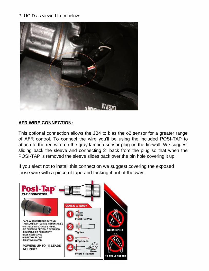
PLUG D as viewed from below:
AFR WIRE CONNECTION:
This optional connection allows the JB4 to bias the o2 sensor for a greater range
of AFR control. To connect the wire you’ll be using the included POSI-TAP to
attach to the red wire on the gray lambda sensor plug on the firewall. We suggest
sliding back the sleeve and connecting 2” back from the plug so that when the
POSI-TAP is removed the sleeve slides back over the pin hole covering it up.
If you elect not to install this connection we suggest covering the exposed
loose wire with a piece of tape and tucking it out of the way.

Below is how the AFR POSI-TAP will look if installed. Note wire colour is
normally blue from JB4 to posi-tap:

OBD cable from inside car:
The installation of this cable is different for right hand drive and left hand drive cars.
LEFT HAND DRIVE INSTALL
The OBD plug (purple) can be found on the panel above the pedals of the car
on the left hand side as pictured below:
The panel can be removed by removing the hex screws holding it in place.
Remove the insulation foam and this will expose a grommet that can be punched
to get the wire pushed into the engine bay. In order to avoid removing the battery
a wire guide or cable tie can be used by taping onto the end of the OBD wire.

The wire will come out of an area behind the battery and can be run to the JB4
unit and plugged into the Molex plug. It is essential the male and female molex
plugs are connected the right way round with no force needed.
RIGHT HAND DRIVE INSTALL
The OBD plug (purple) can be found on the panel above the pedals of the car
on the right hand side as pictured below:

The OBD plug will go into the engine bay as per LHD instructions by passing
over the centre tunnel just above the foot rest. Use a guide and tape the end of
the OBD plug and start by passing it over the centre tunnel through the gap in
the back. Pictured below is the wire taped to a long enough cable tie.
Pull the wire across to the left hand side of the car and follow the LHD
instructions to get it into the cabin.
At this stage the installation is done. When you start the car if the traction
control light and start/stop light are on they will go away as the car drives.
The car will take a few full throttle runs to fully adapt. If you need
additional installation assistance email [email protected]