jaxa’s research and development of - nasa · jaxa’s research and development of unmanned...
TRANSCRIPT

JAXA’s Research and Development ofUnmanned Aircraft System Technologies
for a Disaster Risk Reduction
Japan Aerospace Exploration Agency (JAXA)
Aeronautical Technology Directorate
Daisuke Kubo
1
@IFAR, 06/14/2017
@IFAR, 06/14/2017
K
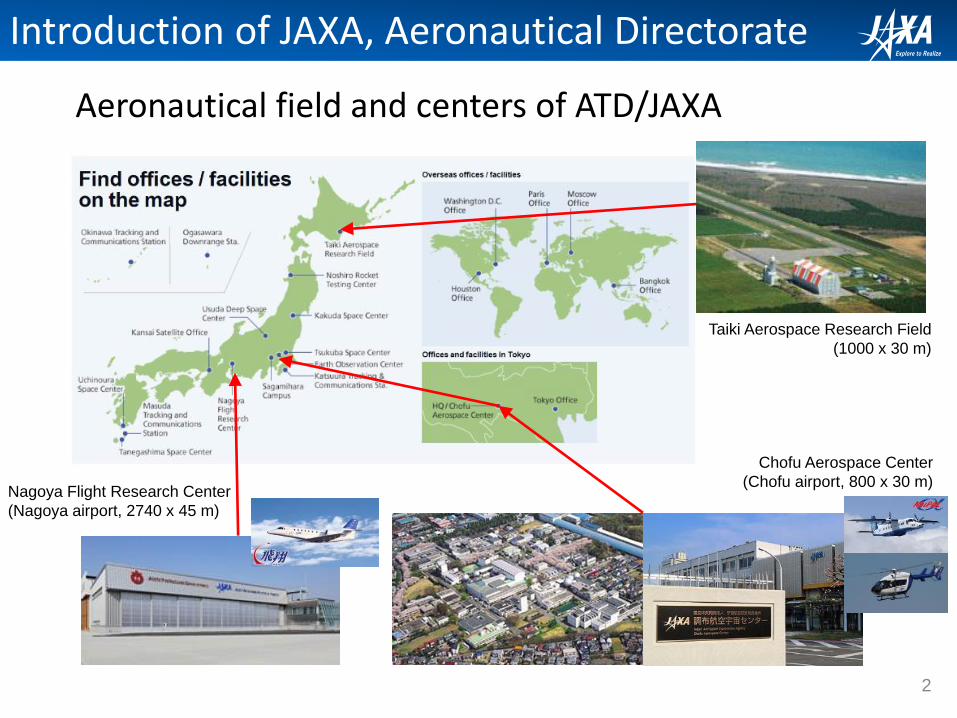
Aeronautical field and centers of ATD/JAXA
2
Taiki Aerospace Research Field
(1000 x 30 m)
Chofu Aerospace Center
(Chofu airport, 800 x 30 m)Nagoya Flight Research Center
(Nagoya airport, 2740 x 45 m)
Introduction of JAXA, Aeronautical Directorate
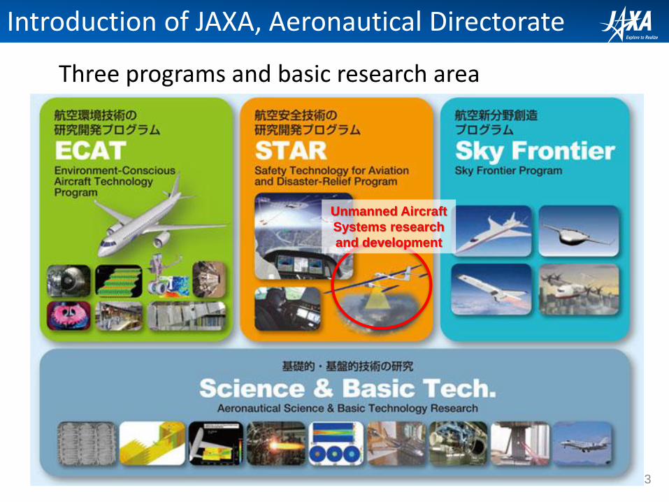
Three programs and basic research area
Unmanned Aircraft
Systems research
and development
3
Introduction of JAXA, Aeronautical Directorate

4
JAXA’s R&D of Unmanned Aircraft Systems (UAS)
2003 - 2007 2008 - 2012 2013 - 2017 2018 - 2022
Weather Observation UAS
Disaster Monitoring UAS
Remote Sensing UAS
Radiation Monitoring UAS (UARMS)
HALE-UAS
Reentry Vehicle Technology
(ALFLEX, HSFD)
Tiltwing VTOL Aerodynamics for Supersonic Transport
(NEXST-1, D-SEND)
Unmanned aircrafts for aerospace technology demonstration
Safety Technologies for sUAS
Recent R&D related to UAS in JAXA

5
II. Small UAS radiation monitoring for Fukushima (2011-)
I. High altitude long endurance UAS conceptual study (2011-)
III. Multiple MAV corporative mission capability (2012-)
IV. UAS traffic management and flight performance (2015-)
Control station Cooperation with a ground robot
Adhoc networkExploration
Autonomous localizationImage of our research
Autonomous task apportionment
JAXA’s R&D of Unmanned Aircraft Systems (UAS)
This talk includes… ongoing 4 UAS R&Ds
6
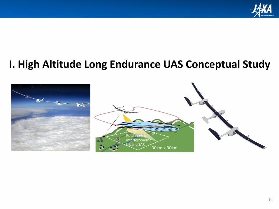
I. High Altitude Long Endurance UAS Conceptual Study

• Seismic intensity 9.0 (the Richter scale)
• Number of missing and dead: 18,446
• Largest earthquake in Japan especially wide areas
• Huge tsunami, wide area
• Resulting nuclear power plant accident
• There is “small number” of actual use of UAS
Sendai airport1)
1) https://ja.wikipedia.org/wiki/%
E6%9D%B1%E6%97%A5%
E6%9C%AC%E5%A4%A7%
E9%9C%87%E7%81%BD
Miyagino-ku, Sendai-city1)
7
Background: Northeast Japan Huge Earthquake, 2011
Miyagino-ku, Sendai-city1)
I. High Altitude Long Endurance UAS Study

8
HALE UAS for a “continuous mission” platform
I. High Altitude Long Endurance UAS Study

9
Target Flight Performance
I. High Altitude Long Endurance UAS Study

10
Operation analysis based on past airport weather data
ETOS [ % ]
滞空時間 [ hr ]
92.836
97.214
98.872
99.549
99.848
99.935
99.978
99.971
99.999
100.000
100.000
100.000
100.000
100.000
100.000
92
94
96
98
100
102
24 36 48 60 72 84 96 108 120 132
空港 1ヵ所 ( 長崎 )
滞空時間 [ hr ]
ETOS [ % ]
98.271
99.558
99.874
99.955
99.991
99.995
100.000
100.000
100.000
100.000
100.000
100.000
100.000
100.000
100.000
92
94
96
98
100
102
24 36 48 60 72 84 96 108 120 132
空港 3ヵ所 ( 長崎 , 帯広 , 茨城 )
Single airport operation
Multiple airports operation
Endurance performance [hr]
Endurance performance [hr]
• Rotational operation
• Constraint of airport weather (cross wind and visibility)
• Cover exclusive economic zone of Japan
• 72 hours endurance enables continuous operation capability
I. High Altitude Long Endurance UAS Study
*ETOS: Effective Time On Station
*ETO
S [%
]*E
TOS
[%]

11
Technological challenges to realize the flight performance
I. High Altitude Long Endurance UAS Study

12
Small scaled HALE demonstration platform (preliminary)
StratosphereCruising flight and mission capability demonstration
Release from balloon
Recovery
Climbing
Balloon releasing
Landing
Current battery energy density is not sufficient
4 kW required for cruising
High solar alt. required
Specifications (preliminary)
Weight 150 kg
Wing span 17 m
Cruise speed 100 kt
Payload 40 kg
Solar-powered high-speed airplane allows large experimental-payload capacity for high altitude flight demonstration, if you compromise that the flight is limited in daytime and summer season.
Cruising
I. High Altitude Long Endurance UAS Study

13
II. Fixed Wing UAS for Radiation Monitoring
JAEA: Japan Atomic Energy AgencyUARMS: Unmanned Airplane for Radiation Monitoring System
UARMS

14
Background: Nuclear Accident and Radiation
Radiation monitoring using manned helicopters
Continuous mission, not only once, but every year for monitor the variation
A number of flights are required
II. Fixed Wing UAS for Radiation Monitoring
15
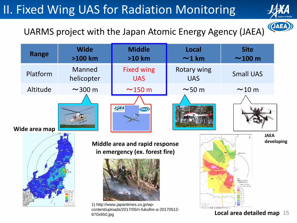
UARMS project with the Japan Atomic Energy Agency (JAEA)
RangeWide
>100 kmMiddle>10 km
Local~1 km
Site~100 m
PlatformManned
helicopterFixed wing
UASRotary wing
UASSmall UAS
Altitude ~300 m ~150 m ~50 m ~10 m
JAEA developing
1) http://www.japantimes.co.jp/wp-
content/uploads/2017/05/n-fukufire-a-20170512-
870x650.jpg
II. Fixed Wing UAS for Radiation Monitoring
Wide area map
Local area detailed map
Middle area and rapid response in emergency (ex. forest fire)
16
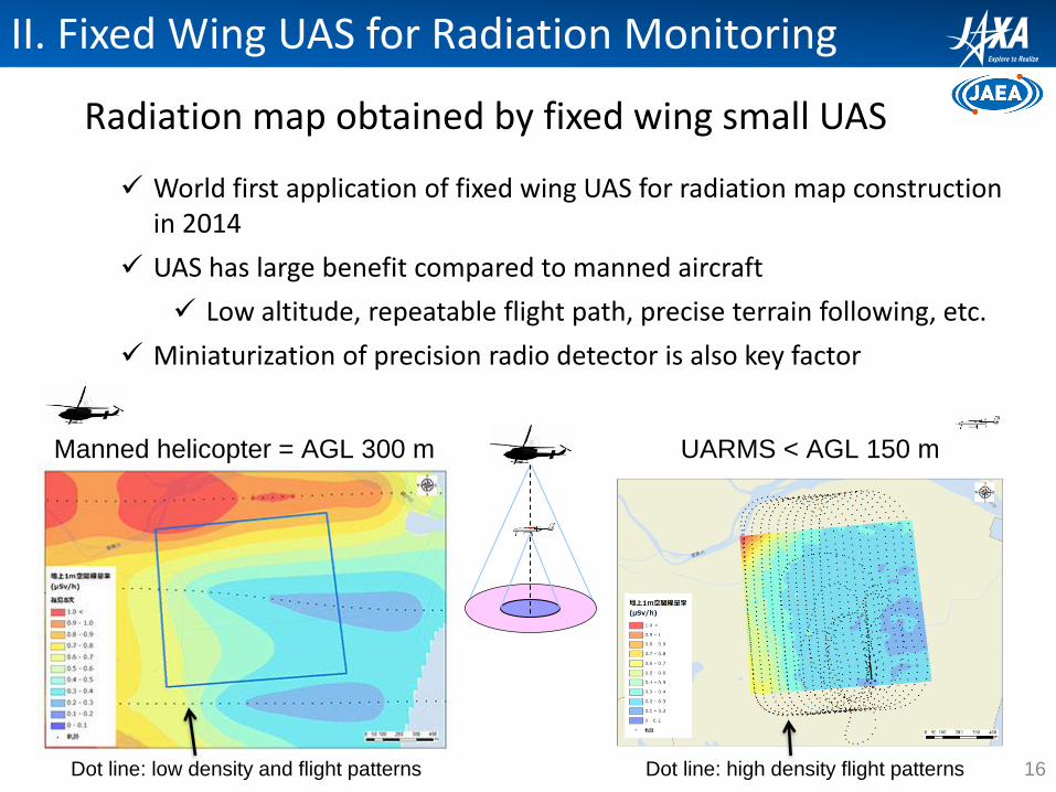
Radiation map obtained by fixed wing small UAS
II. Fixed Wing UAS for Radiation Monitoring
World first application of fixed wing UAS for radiation map construction in 2014
UAS has large benefit compared to manned aircraft
Low altitude, repeatable flight path, precise terrain following, etc.
Miniaturization of precision radio detector is also key factor
UARMS < AGL 150 mManned helicopter = AGL 300 m
Dot line: high density flight patternsDot line: low density and flight patterns
17
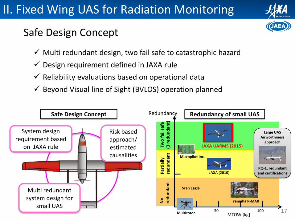
Safe Design Concept
Safe Design Concept
50 100
No
re
du
nd
ant
MTOW [kg]
Two
fai
l saf
e(3
re
du
nd
ant)
Yamaha R-MAX
JAXA (2010)
JAXA UARMS (2015)
Multirotor
Par
tial
lyre
du
nd
ant
Scan Eagle
Micropilot Inc.
Redundancy Redundancy of small UAS
System design requirement based
on JAXA rule
Multi redundant system design for
small UAS
Risk based approach/estimated causalities
II. Fixed Wing UAS for Radiation Monitoring
Multi redundant design, two fail safe to catastrophic hazard
Design requirement defined in JAXA rule
Reliability evaluations based on operational data
Beyond Visual line of Sight (BVLOS) operation planned
RQ-1, redundant and certifications
Large UASAirworthiness
approach
18
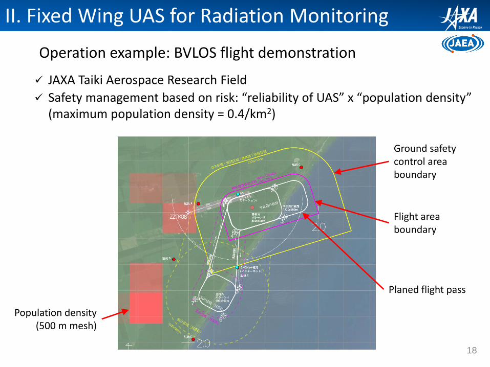
Operation example: BVLOS flight demonstration
JAXA Taiki Aerospace Research Field
Safety management based on risk: “reliability of UAS” x “population density”(maximum population density = 0.4/km2)
II. Fixed Wing UAS for Radiation Monitoring
Flight area boundary
Planed flight pass
Population density(500 m mesh)
Ground safety control area boundary

19
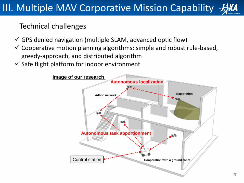
III. Multiple MAV Corporative Mission Capability
Control station Cooperation with a ground robot
Adhoc networkExploration
Autonomous localizationImage of our research
Autonomous task apportionment
20
Technical challenges
Control station Cooperation with a ground robot
Adhoc networkExploration
Autonomous localizationImage of our research
Autonomous task apportionment
GPS denied navigation (multiple SLAM, advanced optic flow) Cooperative motion planning algorithms: simple and robust rule-based,
greedy-approach, and distributed algorithm Safe flight platform for indoor environment
III. Multiple MAV Corporative Mission Capability

21
GPS Denied Navigation
SLAM occupancy grid map overlaid on actual buildingDistortions are issue that is currently addressed via loop closing technique
Small Lidar equipped MAV for SLAM research
SLAM: simultaneous localization and mapping
Developed in ground robotics area and recently applied for MAV
Challenge: multiple flying vehicle data real-time integration
III. Multiple MAV Corporative Mission Capability

22
Red dot: MAV, Blue circle: communication relay constraintSimulation of the algorithm
Cooperative motion planning algorithms
Simple and robust rule-based
Greedy-approach
Distributed algorithm for multipole MAVs operation
Real time HILS
III. Multiple MAV Corporative Mission Capability

23
More safe platform technologies: ducted-fan type MAV
Palm-sized single ducted fan flying robot has a high level of safety because of the shrouded propeller, which is harmless to ground objects and people.The undesired noise because of the high speed rotation and interference of duct structures will be the biggest problem and the research task.
10 cm-duct-diameter ducted fan MAV
15 cm-duct-diameter ducted fan MAV
III. Multiple MAV Corporative Mission Capability
Video
Smaller 7.5 cm-duct-diameter ducted fan MAV

24
IV. UAS Traffic Management and Flight Performance

Background: BVLOS flight for nuclear reconnaissance
• BVLOS (beyond visual line of sight) operation• No long distance command and control links• Flight over populated area at altitude of 1,200
m, 2 hour flight including 1 hour stay over the power plant
• Airspace segregated by civil aviation authority• Safe and regular operation technologies are
required
Fuji-imvac Type B1)
1) http://www.yamazaki-
k.co.jp/airphoto/concept.html
Fukushima dai-ichi nuclear
power plant1)
03/20/2011 (9 days after the
accident)
25
44 miles
Over populated area
Fukushima nuclear power plant
IV. UAS Traffic Management Study
Airfield

Background: more sUAS in recent disaster, now
• Small UAS are now more popular and many VLOS operations
• Small UAS were flown by governmental institute, universities, companies, NPOs, news medias
• Conflict resolution will be required in future disaster
Media drone “chased” disaster
relief helicopter flying low altitude3)
Geographical
Survey
26
Infrastructure damage
assessment by company
IV. UAS Traffic Management Study
Kumamoto earthquake 20162)Heavy rain fall and landslide at
Hiroshima, 20141)
1) https://blogs.yahoo.co.jp/y294maself/34523293.html
2) https://news.yahoo.co.jp/story/146
3) https://weathernews.jp/soramagazine/201705/08/

UTM concept proposed by NASA
27
IV. UAS Traffic Management Study
“Currently, there is no establishedinfrastructure to enable and safelymanage the widespread use oflow-altitude airspace and UASoperations, regardless of the typeof UAS. A UAS traffic management(UTM) system for low-altitudeairspace may be needed, perhapsleveraging concepts from thesystem of roads, lanes, stop signs,rules and lights that govern vehicleson the ground today, whether thevehicles are driven by humans orare automated.”(cited from NASA UTM website)
NASA UTMhttps://utm.arc.nasa.gov/documents.shtml

UTM basic research and experiment in Japan
28
GCSGCS
UAS UTM system
Comm.Network
Flight plan applications Conflict detection
IV. UAS Traffic Management Study

Flight performance study: gust tolerance of small UAS
• Wind tolerance is one of the most important technical challenges for the practical use of drones• sUAS’s relatively light weight and low-
altitude operation
• Too high “drone user’s requirement” of position control accuracy even in gusty wind
• For beyond visual line of sight (BVLOS) operations, guidance accuracy degradation due to the existence of gust wind is an important factor
29
IV. UAS Traffic Management Study
1) http://www.triplem.com.au/melbourne/news/blog/2013/7/wind-to-smash-victoria/
Gusty wind ??? 1)

30
IV. UAS Traffic Management Study
Gust wind tunnel flight for direct gust response evaluation
Using a gust wind tunnel facilities and a motion capture based precise flight control system, direct gust tolerance performance evaluation method was constructed.
Advantages:
Free flight without any aerodynamic interference
Reproducibility and quantitativeness
Limitations:
The wind tunnel can generate only brown-up and down gust, however, cross wind gust is also important
2x2 m low speed WT with gust generator
Precise navigation and
guidance using a motion
capture technology
Actual flight in gust wind tunnel
31
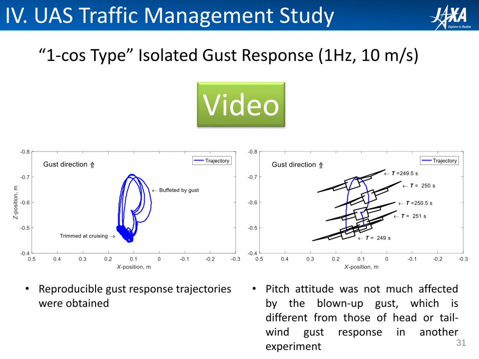
“1-cos Type” Isolated Gust Response (1Hz, 10 m/s)
• Reproducible gust response trajectories were obtained
• Pitch attitude was not much affectedby the blown-up gust, which isdifferent from those of head or tail-wind gust response in anotherexperiment
IV. UAS Traffic Management Study
Video
32
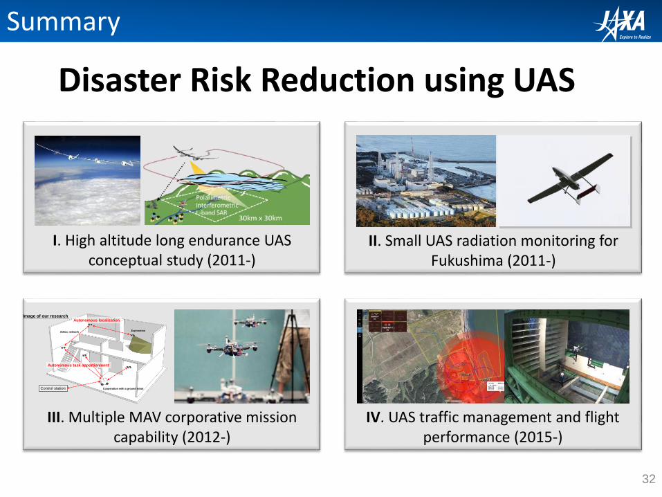
II. Small UAS radiation monitoring for Fukushima (2011-)
I. High altitude long endurance UAS conceptual study (2011-)
III. Multiple MAV corporative mission capability (2012-)
IV. UAS traffic management and flight performance (2015-)
Control station Cooperation with a ground robot
Adhoc networkExploration
Autonomous localizationImage of our research
Autonomous task apportionment
Summary
Disaster Risk Reduction using UAS
Thank you for your kind attention!Please do not hesitate to visit Japan!!
Daisuke Kubo