jas 39 park jet construction manual
TRANSCRIPT

Page 1
�������������� ����� �������� ������ ����������������

Page 2
This model was designed to be built from either BlueCore fan-fold foam or 6 mm Depron foam. If using BlueCore, note you’ll need to peel the film backing off the fuselage exterior parts to allow sanding the fuselage corners to shape. Leave the film on the wing and empennage parts since it adds strength, durability, and smoothness.
This model can be built using the following types of adhesives:
• Epoxy • Odorless cyanoacrylate (CA) with accelerator • UHU Creativ for Styrofoam (or UHU POR) • 3M 77 spray adhesive • Hot glue gun • ProBond (or Gorilla Glue)
To minimize weight, try to use as little epoxy as possible on this model, saving it for only critical joints such as wing spars and motor mounts. The majority of construction should use a lightweight and quick-drying adhesive such as CA, UHU Creativ, or 3M 77. I personally use 3M 77 and UHU Creativ (picture at left) for the majority of construction. Begin by cutting out all of the paper parts templates with scissors, trimming them to within approximately 1/8” of the lines. Then test fit all of the templates onto the foam sheet, trying to minimize wasted foam as much as possible. Once you’re satisfied with the arrangement, remove each template individually and spray the back of the template LIGHTLY with 3M 77 spray adhesive. Then replace the template onto the same spot on the foam sheet. Repeat for every template. After all the templates are tacked onto the foam, cut out all the pieces by cutting on the lines with a SHARP hobby knife. When done, peel the paper templates off of each piece and discard.

Page 3
1. Start assembly with the forward fuselage. Lay the two fuselage sides down flat on the work bench and glue the foam corner doublers to the locations shown on the plans. Make sure to make two mirror image parts—a left side and a right side. Either 3M 77 spray adhesive or UHU Creativ works best for this step. [Note: These photos show the prototype model, which used balsa triangle stock at the corners. The updated design now uses foam strip doublers at the corners, which are just as strong and can be sanded to a more rounded shape.] After the glue has dried, glue the two fuselage bulkheads to one of the fuselage sides at the locations shown, making sure they are perpendicular.
2. Glue the two fuselage sides together. Set the sides upright and flat on the workbench, apply glue to the edge of the bulkheads, and push the sides together. Note the aft end is left open at this point—it will be glued together later. Glue on the forward fuselage bottom piece and the forward fuselage top pieces.

Page 4
3. Laminate all of the nosecone pieces together using 3M 77 adhesive. Then glue the nosecone block to the front of the fuselage. Once the glue has dried, sand the nosecone and forward fuselage to shape. Start by tracing the top outline of the nosecone onto the foam and cut to shape with a long knife or saw. Begin with coarse sandpaper (100 grit) to rough out the basic shape, then move to a finer sandpaper (220 grit) to do the final shaping. End with 320 grit sandpaper to do the final polish sanding and provide a very smooth surface.

Page 5
4. Laminate and carve the canopy to shape using the same procedure as the nosecone.
5. Glue the small plywood canard pivot supports to the fuselage sides at the location shown on the plans. Then stack the two sides together, carefully align them, and drill the 3/16” diameter hole through both pieces for the canard pivots (a drill press is highly recommended for this step to ensure the hole is exactly perpendicular to the sides). Glue the foam corner doublers to the fuselage sides at the locations shown on the plans. Make sure to make left and right mirror image pieces.
Page 6
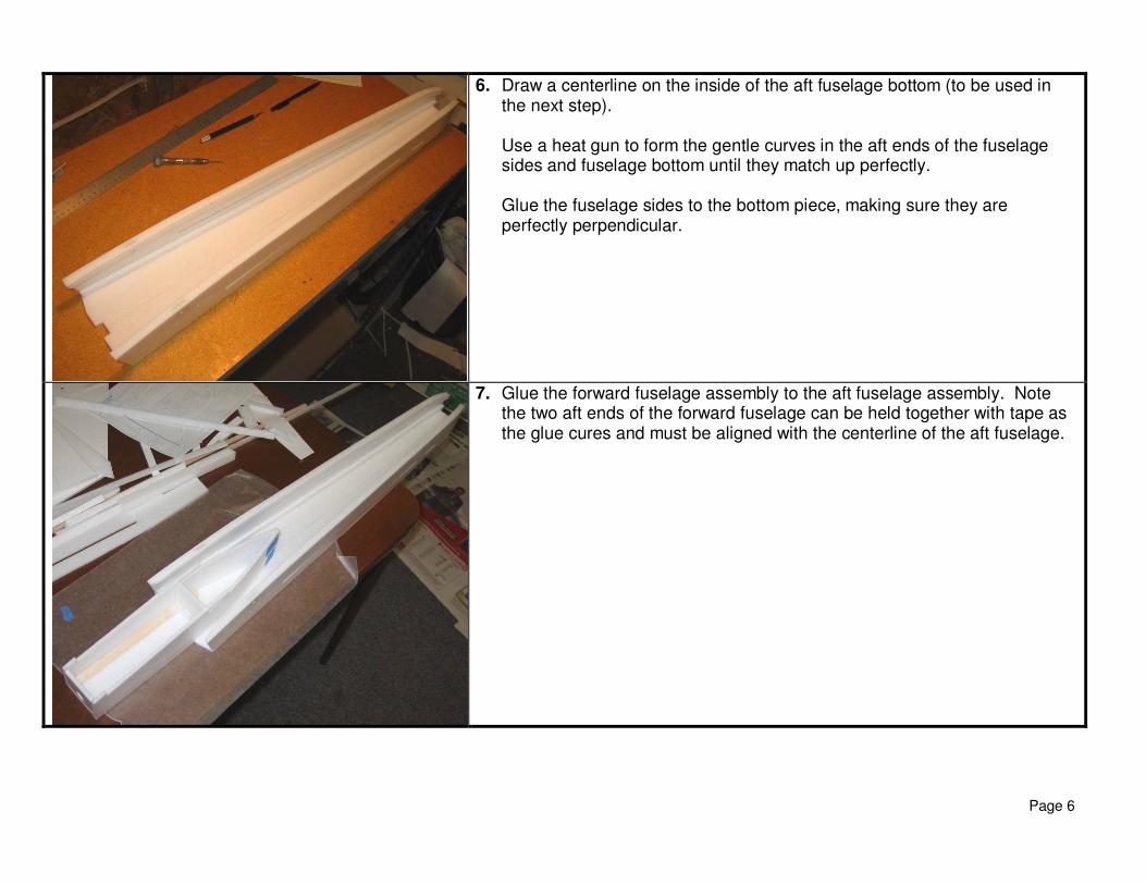
6. Draw a centerline on the inside of the aft fuselage bottom (to be used in the next step). Use a heat gun to form the gentle curves in the aft ends of the fuselage sides and fuselage bottom until they match up perfectly. Glue the fuselage sides to the bottom piece, making sure they are perfectly perpendicular.
7. Glue the forward fuselage assembly to the aft fuselage assembly. Note the two aft ends of the forward fuselage can be held together with tape as the glue cures and must be aligned with the centerline of the aft fuselage.

Page 7
8. Glue the hardwood motor stick into the foam motor mount with 5 minute epoxy and let it cure. Then glue the motor mount into the aft fuselage (5 min epoxy recommended), making sure it is aligned with the centerline drawn on the fuselage bottom.
9. Sand the leading edge of the wing to a well-rounded shape, and sand the trailing edge to a gentle taper. Cut a slot for the carbon tube wing spar. Lay the wing down on a flat surface and use 30 minute epoxy to glue the carbon wing spar in place. Place heavy books over wax paper on top of the wing to hold the wing perfectly flat as the glue cures. After the glue has cured, cut the flaperons free from the wing. Then cut a 45 degree bevel in the leading edge of the flaperons using a ruler and a hobby knife. Hinge the flaperons to the wing using your hinge of choice. I recommend 3M Satin tape hinges, running full span on the top and bottom.

Page 8
10. Slide the wing into the fuselage. Make sure it is perfectly flat and perpendicular to the fuselage centerline, trim and shim as required, and then glue into place.
11. Next install the hardware for the pivoting canard. The 0.157” diameter carbon canard rod pivots inside two 0.5” pieces of 3/16” diameter aluminum, which are supported by two small squares of 1/64” ply glued to the fuselage sides (study the plans carefully here!). Two end stops (made from nylon servo arms drilled out to fit the rod and with the arms snipped off) butt up against the aluminum tubes to keep the rod from sliding left and right. The control horn on the pivot rod is made from either a spare nylon servo arm or a common nylon control horn cut to fit. Sand the leading edge of the canard to a well-rounded shape, and sand the trailing edge to a gentle taper. Test fit the aluminum tubes into the holes and slide the carbon rod into both pieces. Adjust the fit as required until the carbon rod is perfectly straight and turns freely, and then glue the aluminum tubes in place using CA or epoxy.

Page 9
After the glue is cured, remove the carbon tube and glue it into one of the canard halves at the location shown (5 minute epoxy recommended). After the glue is cured, slide the carbon tube back into the airplane, and slide on the two end stop bearings and the pivot rod control horn (in the proper order). Install the stabilator servo and connecting hardware (I recommend 1/16” threaded music wire, Dubro EZ connectors, and a steel clevis). After everything is connected and aligned, glue on the second canard half, making sure it is perfectly aligned with both the fuselage and the other stabilator half (5 minute epoxy recommended). Then glue the end stop bearings and the control horn onto the pivot rod.
12. OPTIONAL: A rudder can be installed if desired. While it is very nice to have on this model, it is not mandatory and the model will fly fine without it. It is useful mostly for directional control during high angle of attack maneuvering and also for aerobatics. In fact, during extreme high alpha flight (60 degrees+), the rudder is the only real means of steering the plane since the ailerons become ineffective. If installing a rudder, install the hardware now. I located the rudder servo next to the canard servo in the forward fuselage and ran a thin carbon rod for the length of the fuselage, supported throughout by small scraps of foam. 1/32” music wire is attached to the end and bent to a shape that allows it to exit the fuselage and connect with the rudder control horn (see the plans for a template).

Page 10
13. Glue the fuselage top into place as shown. If installing a rudder, cut an exit slot for the pushrod end and pull the pushrod up through the slot.
14. Glue the 3mm Depron inlet spacers onto each side of the fuselage, and then glue the 3mm Depron inlet fences on top of each spacer as shown.

Page 11
15. Glue the turtledeck sides onto the fuselage top, taking care to form the curves shown on the plans and making sure the ends are on the fuselage centerline. Glue on the turtledeck top piece. Laminate the fuselage top spine and glue into place.
16. Sand the leading edge of the vertical tail to a well-rounded shape, and the trailing edge to a tapered shape. Glue on the 3mm Depron vertical tail radar fairings onto each side of the tail, and then shape with sandpaper. If installing a rudder, cut the rudder free, bevel the leading edge, and hinge with 3M Satin tape. Install the plywood control horn. Glue the vertical tail on using epoxy. Connect the rudder control horn to the pushrod end as you glue the tail in place. Apply a single strip of 3M Satin tape around all leading edges on the wing, canard, and vertical tail. The tape helps provide a very smooth leading edge shape and also provides more durability against the inevitable “hangar rash.”

Page 12
17. Now thoroughly sand the entire fuselage to round all corners. Start with coarse sandpaper (60 or 100 grit) to do the basic shaping quickly, and then progressively work your way to finer grades of sandpaper (150, 200, and then 320). Sand the corners of the aft fuselage especially well, trying to approximate the rounded shape of the Gripen fuselage. I used a power orbital sander to make quick work of this.

Page 13
18. Cut holes in the fuselage sides to fit the elevon servos tightly, and install the servos. Install the elevon control horns, and make a pushrod from 1/32” music wire (using Z-bends at both ends).
19. The canopy is removable to allow easy access to the battery compartment. It is held in place with two bamboo skewers (or toothpicks) forward that slide into matching holes in the forward bulkhead, and two small strips of Velcro aft that are mounted to short pieces of ¼” balsa triangle stock. Cut two 2” lengths of bamboo and sharpen both ends. Stick the bamboo into the foam at the front of the canopy so that only ½” protrudes and glue into place. After the glue dries, push the canopy onto the airplane so that the protruding ends poke holes into the forward bulkhead. Then glue the Velcro mounts to the fuselage sides as shown on the plans and attach the matching Velcro pieces to the mounts and to the canopy. Cut a hatch in the turtledeck as shown to allow access to the receiver. Use small strips of tape to keep this hatch in place in flight.

Page 14
20. Install the receiver and speed control. Make a wire extension to connect the battery in the forward fuselage to the speed control in the aft fuselage. Use at least 16 gauge wire. To reduce the amount of RF interference with the receiver, twist the wires in the extension tightly together and also wrap them tightly with 3 or 4 layers of household aluminum foil. This will provide shielding that should reduce interference. Solder the connectors of choice to both ends (Deans Ultra connectors are recommended). Install Velcro in the forward fuselage to hold the battery in place.
21. Attach the motor to the wood motor mount stick. Two screws (one on each side) can be used to hold the motor on. Make sure the thrust line is set with zero right/left and zero up/down thrust. If not, trim and shim the wood mounting stick as required. Plug the motor into the leads to the speed control. Note that a “soft-mount” prop adapter is recommended to prevent damage to the prop or the model during landings.

Page 15
22. CONGRATULATIONS! Your model is now complete. The model can be flown as is or can be painted using standard acrylic craft paint (available at most craft stores) applied with either a brush or airbrush. Remember to wipe the foam with rubbing alcohol before painting to remove any grease or dirt. Rough areas such as the canopy and nosecone should be filled with standard wall spackling compound thinned with water, which fills the holes and can be sanded to a very smooth finish (with minimal weight gain).

Page 16
Additional Photos

Page 17
Flight Setup 1. This model flies best with canard and elevon mixing. Set up a mix so that full up elevator command drives the canard 3/4"
trailing edge down and the elevons +/- 3/8” trailing edge up. If your transmitter does not support mixing, this airplane will fly fine with either the canard as the only primary pitch control or the elevons as the only pitch control. The model will not be able to high angle of attack maneuvers as well without mixing, but it will fly fine for normal sport flying.
2. Adjust the controls to provide the following recommended deflections (all dimensions are measured at the root trailing edge): • Canard: +/- 3/4” • Elevons: +/- 3/4” (ailerons), +/- 3/8” (elevator), • Rudder: +/- 1.5”
3. I recommend using -60% exponential rates on elevator and ailerons. 4. Recommended hand launch procedure: Grip the airplane near the CG, set 50% throttle, and throw it moderately hard straight
ahead and parallel to the ground. Be careful to keep your hand away from the prop as you throw it! It’s important to launch at only 50% throttle to minimize prop torque effects at launch, which could cause the model to roll left immediately after you throw it.