japan radio test report - texas instrumentsprocessors.wiki.ti.com/images/b/bc/jr731625_r01... ·...
TRANSCRIPT

SPORTON INTERNATIONAL INC. Page Number : 1 of 28
TEL : 886-3-327-3456 Report Issued Date : Jun. 10, 2017
FAX : 886-3-328-4978 Report Version : Rev. 01
Report Template No.: BU5-JRRADIOWLAN2G4 Version 1.0
JAPAN Radio Test Report – WLAN 2.4GHz Band Report No. : JR731625
JAPAN Radio Test Report
WLAN 2.4GHz Band
APPLICANT : Texas Instruments Incorporated
PRODUCT NAME : 2.4GHz Wi-Fi® Module
MODEL NAME : CC3220MODASF12MON, CC3220MODASM2MON, CC3220MODSF12MOB, CC3220MODSM2MOB
TYPE EMISSIONS : 14M2G1D (DSSS_802.11b) ; 16M9G1D/D1D (OFDM_802.11g) ; 18M2G1D/D1D (OFDM_802.11n_HT20)
DECLARATION OUTPUT POWER
: 3.50 mW/MHz (DSSS_802.11b) ; 2.50 mW/MHz (OFDM_802.11g) ; 2.50 mW/MHz (OFDM_802.11n_HT20)
STANDARD : Article 49‐20 and the relevant articles of the Ordinance Regulating Radio Equipment
TEST PROCEDURE
: MIC Notice No.88 Appendix No.43

SPORTON INTERNATIONAL INC. Page Number : 2 of 28
TEL : 886-3-327-3456 Report Issued Date : Jun. 10, 2017
FAX : 886-3-328-4978 Report Version : Rev. 01
Report Template No.: BU5-JRRADIOWLAN2G4 Version 1.0
JAPAN Radio Test Report – WLAN 2.4GHz Band Report No. : JR731625
The product sample received on Mar. 16, 2017 and completely tested on May 26, 2017. We,
SPORTON INTERNATIONAL INC., would like to declare that the tested sample has been
evaluated in accordance with the procedures given in MIC Notice No.88 Appendix No.43
and shown to be compliant with the applicable technical standards. Article 2 Paragraph 1
Item 19 of the Certificate Ordinance of the Radio Law indicates the classification of the
specified radio equipment.
The test results in this report apply exclusively to the tested model / sample. Without written
approval of SPORTON INTERNATIONAL INC., the test report shall not be reproduced except
in full.
Review by: Louis Wu Approved by: Jones Tsai / Manager
SPORTON INTERNATIONAL INC. No. 52, Hwa Ya 1
st Rd., Hwa Ya Technology Park, Kwei-Shan District, Tao Yuan City, Taiwan, R.O.C.

SPORTON INTERNATIONAL INC. Page Number : 3 of 28
TEL : 886-3-327-3456 Report Issued Date : Jun. 10, 2017
FAX : 886-3-328-4978 Report Version : Rev. 01
Report Template No.: BU5-JRRADIOWLAN2G4 Version 1.0
JAPAN Radio Test Report – WLAN 2.4GHz Band Report No. : JR731625
TABLE OF CONTENTS
REVISION HISTORY .......................................................................................................................................... 4
SUMMARY OF TEST RESULT ......................................................................................................................... 5
1 GENERAL DESCRIPTION .......................................................................................................................... 6
1.1 Applicant ............................................................................................................................................ 6
1.2 Manufacturer ...................................................................................................................................... 6 1.3 Feature of Equipment Under Test ..................................................................................................... 7 1.4 Modification of EUT ........................................................................................................................... 9 1.5 Testing Site ...................................................................................................................................... 10 1.6 Applied Standards ........................................................................................................................... 10 1.7 Ancillary Equipment List .................................................................................................................. 10
2 TEST CONFIGURATION OF EQUIPMENT UNDER TEST ...................................................................... 11
2.1 Carrier Frequency Channel ............................................................................................................. 11 2.2 EUT Operation Test Setup .............................................................................................................. 11
3 TEST RESULT .......................................................................................................................................... 12
3.1 Frequency Tolerance Measurement ................................................................................................ 12 3.2 Occupied Bandwidth and Spread-spectrum Bandwidth / Spread Factor Measurement ................. 13 3.3 Unwanted Emission Intensity Measurement ................................................................................... 15 3.4 RF Output Power / Tolerance .......................................................................................................... 17 3.5 Limitation of Collateral Emission of Receiver Measurement ........................................................... 19 3.6 Transmission Antenna Gain (EIRP Antenna Power) Measurement ............................................... 21
3.7 Transmission Radiation Angle Width (3dB Beamwidth) Measurement ........................................... 23 3.8 Radio Interference Prevention Capability Measurement ................................................................. 25 3.9 Carrier Sense ................................................................................................................................... 26 3.10 Construction Protection Confirmation Method ................................................................................. 27
4 LIST OF MEASURING EQUIPMENT ........................................................................................................ 28
APPENDIX A. SETUP PHOTOGRAPHS
APPENDIX B. TEST RESULTS
APPENDIX C. TEST PLOTS

SPORTON INTERNATIONAL INC. Page Number : 4 of 28
TEL : 886-3-327-3456 Report Issued Date : Jun. 10, 2017
FAX : 886-3-328-4978 Report Version : Rev. 01
Report Template No.: BU5-JRRADIOWLAN2G4 Version 1.0
JAPAN Radio Test Report – WLAN 2.4GHz Band Report No. : JR731625
REVISION HISTORY
REPORT NO. VERSION DESCRIPTION ISSUED DATE
JR731625 Rev. 01 Initial issue of report Jun. 10, 2017

SPORTON INTERNATIONAL INC. Page Number : 5 of 28
TEL : 886-3-327-3456 Report Issued Date : Jun. 10, 2017
FAX : 886-3-328-4978 Report Version : Rev. 01
Report Template No.: BU5-JRRADIOWLAN2G4 Version 1.0
JAPAN Radio Test Report – WLAN 2.4GHz Band Report No. : JR731625
SUMMARY OF TEST RESULT
Report Section Description Result
3.1 Frequency Tolerance Pass
3.2 Occupied Bandwidth and Spread-spectrum Bandwidth / Spread
Factor Pass
3.3 Unwanted Emission Intensity Pass
3.4 RF Output Power / Tolerance Pass
3.5 Limitation of Collateral Emission of Receiver Pass
3.6 Transmission Antenna Gain
(EIRP Antenna Power) N/A
3.7 Transmission Radiation Angle Width
(3dB Beam width) N/A
3.8 Radio Interference Prevention Capability Pass
3.9 Carrier Sense Function N/A
3.10 Construction Protection Confirmation Pass

SPORTON INTERNATIONAL INC. Page Number : 6 of 28
TEL : 886-3-327-3456 Report Issued Date : Jun. 10, 2017
FAX : 886-3-328-4978 Report Version : Rev. 01
Report Template No.: BU5-JRRADIOWLAN2G4 Version 1.0
JAPAN Radio Test Report – WLAN 2.4GHz Band Report No. : JR731625
1 General Description
1.1 Applicant
Texas Instruments Incorporated
12500 TI BLVD., Dallas Texas, 75243
1.2 Manufacturer
Texas Instruments Incorporated
12500 TI BLVD., Dallas Texas, 75243
SPORTON INTERNATIONAL INC. Page Number : 7 of 28
TEL : 886-3-327-3456 Report Issued Date : Jun. 10, 2017
FAX : 886-3-328-4978 Report Version : Rev. 01
Report Template No.: BU5-JRRADIOWLAN2G4 Version 1.0
JAPAN Radio Test Report – WLAN 2.4GHz Band Report No. : JR731625
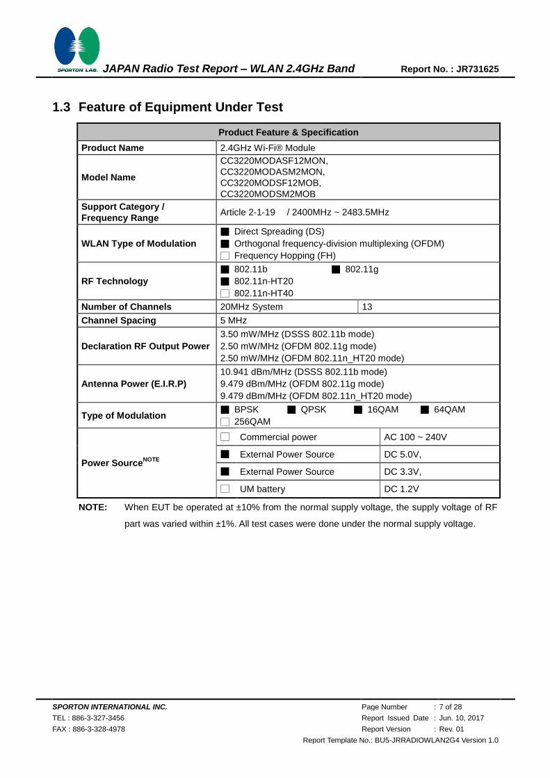
1.3 Feature of Equipment Under Test
Product Feature & Specification
Product Name 2.4GHz Wi-Fi® Module
Model Name
CC3220MODASF12MON,
CC3220MODASM2MON,
CC3220MODSF12MOB,
CC3220MODSM2MOB
Support Category /
Frequency Range Article 2-1-19 / 2400MHz ~ 2483.5MHz
WLAN Type of Modulation
■ Direct Spreading (DS)
■ Orthogonal frequency-division multiplexing (OFDM)
□ Frequency Hopping (FH)
RF Technology
■ 802.11b ■ 802.11g
■ 802.11n-HT20
□ 802.11n-HT40
Number of Channels 20MHz System 13
Channel Spacing 5 MHz
Declaration RF Output Power
3.50 mW/MHz (DSSS 802.11b mode)
2.50 mW/MHz (OFDM 802.11g mode)
2.50 mW/MHz (OFDM 802.11n_HT20 mode)
Antenna Power (E.I.R.P)
10.941 dBm/MHz (DSSS 802.11b mode)
9.479 dBm/MHz (OFDM 802.11g mode)
9.479 dBm/MHz (OFDM 802.11n_HT20 mode)
Type of Modulation ■ BPSK ■ QPSK ■ 16QAM ■ 64QAM
□ 256QAM
Power SourceNOTE
□ Commercial power AC 100 ~ 240V
■ External Power Source DC 5.0V,
■ External Power Source DC 3.3V,
□ UM battery DC 1.2V
NOTE: When EUT be operated at ±10% from the normal supply voltage, the supply voltage of RF
part was varied within ±1%. All test cases were done under the normal supply voltage.

SPORTON INTERNATIONAL INC. Page Number : 8 of 28
TEL : 886-3-327-3456 Report Issued Date : Jun. 10, 2017
FAX : 886-3-328-4978 Report Version : Rev. 01
Report Template No.: BU5-JRRADIOWLAN2G4 Version 1.0
JAPAN Radio Test Report – WLAN 2.4GHz Band Report No. : JR731625
Power Supply voltage
5.00 Vdc (Nominal)
Power Supply voltage
5.50 Vdc (+10%)
Power Supply voltage
4.50 Vdc (-10%)
3.3 3.3 3.3
Measurement point
Antenna Information
Item Brand Name Antenna Type Device Name Peak Gain
(2.4GHz)
1. FoxCon PCB T77H533 2.5 dBi
2. Ethertronics Dipole 1000423 -0.6 dBi
3.
LSR
Rubber Whip /
Dipole
001-0012 2 dBi
4. 080-0013 2 dBi
5. 080-0014 2 dBi
6. PIFA
001-0016 2.5 dBi
7. 001-0021 2.5 dBi
8. Laird PCB
CAF94504 2 dBi
9. CAF94505 2 dBi
10. Pulse Ceramic Chip W3006 3.2 dBi
11. ACX Multilayer Chip
AT3216-BR2R7HAA 0.5 dBi
12. AT312-T2R4PAA 1.5 dBi
13. CUSTOM
ANTENNA Inverted F CUSTOM ANTENNA 3.3 dBi
14.
TDK
Multilayer
Ceramic Chip
Antenna
ANT016008LCD2442MA1 1.6 dBi
15. ANT016008LCD2442MA2 2.5 dBi
16. Mitsubishi
Material
Chip Antenna AM03DP-ST01 1.6 dBi
17. Antenna Unit UB18CP-100ST01 -1.0 dBi

SPORTON INTERNATIONAL INC. Page Number : 9 of 28
TEL : 886-3-327-3456 Report Issued Date : Jun. 10, 2017
FAX : 886-3-328-4978 Report Version : Rev. 01
Report Template No.: BU5-JRRADIOWLAN2G4 Version 1.0
JAPAN Radio Test Report – WLAN 2.4GHz Band Report No. : JR731625
Antenna Information
Item Brand Name Antenna Type Device Name Peak Gain
(2.4GHz)
18.
Taiyo Yuden
Chip Antenna /
Herical
Monopole
AF216M245001 1.5 dBi
19. Chip Antenna
/Monopole Type
AH212M245001 1.3 dBi
20. AH316M245001 1.9 dBi
21.
Antenna
Technology Dipole
AA2402SPU 2.0 dBi
22. AA2402RSPU 2.0 dBi
23. AA2402A-UFLLP 2.0 dBi
24. AA2402AU-UFLLP 2.0 dBi
25.
Staf Mono-pole
1019-016 2.14 dBi
26. 1019-017 2.14 dBi
27. 1019-018 2.14 dBi
28. 1019-019 2.14 dBi
29.
Map
Electronics Rubber Whip
MEIWX-2411SAXX-2400 2.0 dBi
30. MEIWX-2411RSXX-2400 2.0 dBi
31. MEIWX-1511RSXX-2400 5.0 dBi
32. MEIWX-151XSAXX-2400 5.0 dBi
33. MEIWX-1451RSXX-2400 4.0 dBi
34. MEIWX-282XSAXX-2400 2.0 dBi
35. MEIWX-282XRSXX-2400 2.0 dBi
36. MEIWF-HP01RS2X-2400 2.0 dBi
37. Yageo Chip ANT3216A063R2400A 1.69 dBi
38. Mag Layers
Scientific Chip
LTA-3216-2G4S3-A1 1 dBi
39. LTA-3216-2G4S3-A3 2 dBi
40.
Advantech
Rubber Whip /
Dipole AN2450-5706RS 2.38 dBi
41. Rubber Whip /
Dipole AN2450-5010BRS 5.03 dBi
42. Rubber Whip /
Dipole AN2450-92K01BRS 5.03 dBi
43. Rubber Whip /
Dipole R-AN2400-5701RS 3.3 dBi
44. Rubber Whip /
Dipole AC0104158R00 5.5 dBi
Remark: The above EUT's information was declared by manufacturer. Please refer to the
specifications or user's manual for more detailed description.
1.4 Modification of EUT
No modifications are made to the EUT during all test items.

SPORTON INTERNATIONAL INC. Page Number : 10 of 28
TEL : 886-3-327-3456 Report Issued Date : Jun. 10, 2017
FAX : 886-3-328-4978 Report Version : Rev. 01
Report Template No.: BU5-JRRADIOWLAN2G4 Version 1.0
JAPAN Radio Test Report – WLAN 2.4GHz Band Report No. : JR731625
1.5 Testing Site
Test Site SPORTON INTERNATIONAL INC.
Test Site Location
No. 52, Hwa Ya 1st Rd., Hwa Ya Technology Park,
Kwei-Shan District, Tao Yuan City, Taiwan, R.O.C.
TEL: +886-3-3273456 / FAX: +886-3-3284978
Test Site No. Sporton Site No.:
TH02-HY
Test Items Uncertainty Remark
Occupied Channel Bandwidth ± 0.49 % Confidence 95%
RF output power, conducted ±0.61 dB Confidence 95%
Power density, conducted ±0.60 dB Confidence 95%
Temperature ±0.8 °C Confidence 95%
Humidity ±3 % Confidence 95%
Time ±0.33 % Confidence 95%
1.6 Applied Standards
According to the specifications of the manufacturer, the EUT must comply with the requirements of the
following standards:
Article 49‐20 and the relevant articles of the Ordinance Regulating Radio Equipment
Remark:
1. All test items were verified and recorded according to the standards and without any deviation
during the test.
2. The measurement was implemented in accordance with MIC Notice No. 88 Appendix No. 43.
1.7 Ancillary Equipment List
None.

SPORTON INTERNATIONAL INC. Page Number : 11 of 28
TEL : 886-3-327-3456 Report Issued Date : Jun. 10, 2017
FAX : 886-3-328-4978 Report Version : Rev. 01
Report Template No.: BU5-JRRADIOWLAN2G4 Version 1.0
JAPAN Radio Test Report – WLAN 2.4GHz Band Report No. : JR731625
2 Test Configuration of Equipment Under Test
2.1 Carrier Frequency Channel
Channel Frequency
(MHz)
1 2412
2 2417
3 2422
4 2427
5 2432
6 2437
7 2442
8 2447
9 2452
10 2457
11 2462
12 2467
13 2472
2.2 EUT Operation Test Setup
During testing, RF test program provided by the customer was used to control the operating channel as
well as the output power level.

SPORTON INTERNATIONAL INC. Page Number : 12 of 28
TEL : 886-3-327-3456 Report Issued Date : Jun. 10, 2017
FAX : 886-3-328-4978 Report Version : Rev. 01
Report Template No.: BU5-JRRADIOWLAN2G4 Version 1.0
JAPAN Radio Test Report – WLAN 2.4GHz Band Report No. : JR731625
3 Test Result
3.1 Frequency Tolerance Measurement
3.1.1 Limit
Item Limits
Frequency Tolerance ≤50ppm
3.1.2 Measuring Instruments
See list of measuring instruments of this test report.
3.1.3 Test Procedure
1. Frequency accuracy of instrument shall be less than 10% of limits tolerance (5ppm).
2. Two methods for the item
a. CW Tone method
i. Setting of SA is following as: RBW:1kHz / VBW:30kHz.
ii. Maker Max. level to get measuring frequency f.
b. 10dB down method
i. Setting of SA is following as: RBW:100kHz / VBW: 100kHz / Trace: MaxHold
ii. Display line Level = Max. level – 10dB to place two markers, highest(fH) and lowest(fL)
frequency
iii. Determine measuring frequency f = (Fh+fL)/2
3. The frequency tolerance test case is directly measured using spectrum analyzer. Then the
frequency error formula is (f-fc)/fc×106 ppm and the limit is less than ±50ppm.
3.1.4 Test Setup
3.1.5 Test Deviation
There is no deviation with the original standard.
3.1.6 EUT Operation during Test
The EUT was programmed to be in continuously transmitting mode.
3.1.7 Test Result of Frequency Tolerance
Please refer to Appendix B.

SPORTON INTERNATIONAL INC. Page Number : 13 of 28
TEL : 886-3-327-3456 Report Issued Date : Jun. 10, 2017
FAX : 886-3-328-4978 Report Version : Rev. 01
Report Template No.: BU5-JRRADIOWLAN2G4 Version 1.0
JAPAN Radio Test Report – WLAN 2.4GHz Band Report No. : JR731625
3.2 Occupied Bandwidth and Spread-spectrum Bandwidth / Spread Factor Measurement
3.2.1 Limit
Item Limits
Occupied Band Width DS ≤ 26MHz; Others ≤ 26MHz
OFDM (For BW=20MHz) ≤ 26MHz
OFDM (For BW=40MHz) ≤ 38MHz
Spreading Bandwidth DS ≥ 500 kHz
3.2.2 Measuring Instruments
See list of measuring instruments of this test report.
3.2.3 Test Procedures
1. Setting of SA is following as: RBW: 300KHz / VBW:300KHz / Sweep Mode: Continuous sweep /
Detect mode: Positive peak / Trace mode: Max hold.
2. EUT have transmitted each modulation signal and fixed channelize (For DSSS or OFDM
Device). SA set to 99% of occupied bandwidth to measure occupied bandwidth. The limit is less
than 26MHz (For DSSS or OFDM Device).
3. SA set to 90% of occupied bandwidth to measure Spread Spectrum Bandwidth and must
greater than 500kHz.
4. Spread Spectrum Factor = Spread Spectrum Bandwidth / modulation rate of EUT.
5. Spread Spectrum Factor limit is greater than 5.
3.2.4 Test Setup

SPORTON INTERNATIONAL INC. Page Number : 14 of 28
TEL : 886-3-327-3456 Report Issued Date : Jun. 10, 2017
FAX : 886-3-328-4978 Report Version : Rev. 01
Report Template No.: BU5-JRRADIOWLAN2G4 Version 1.0
JAPAN Radio Test Report – WLAN 2.4GHz Band Report No. : JR731625
3.2.5 Test Deviation
There is no deviation with the original standard.
3.2.6 EUT Operation during Test
The EUT was programmed to be in continuously transmitting mode.
3.2.7 Test Result of Occupied Bandwidth and Spread-spectrum Bandwidth / Spread
Factor Measurement
Please refer to Appendix B.

SPORTON INTERNATIONAL INC. Page Number : 15 of 28
TEL : 886-3-327-3456 Report Issued Date : Jun. 10, 2017
FAX : 886-3-328-4978 Report Version : Rev. 01
Report Template No.: BU5-JRRADIOWLAN2G4 Version 1.0
JAPAN Radio Test Report – WLAN 2.4GHz Band Report No. : JR731625
3.3 Unwanted Emission Intensity Measurement
3.3.1 Limit
Item Limits
Tx Spurious Emission
≤ 2.5 μW (2387MHz > f ; 2496.5MHz < f )
≤ 25 μW
(2387MHz ≤ f <2400MHz) and (2483.5MHz < f ≤ 2496.5MHz)
3.3.2 Measuring Instruments
See list of measuring instruments of this test report.
3.3.3 Test Procedures
1. EUT have transmitted the maximum power and fixed channelize.
2. Setting of SA is following as: RBW:1MHz / VBW:1MHz above 1GHz, Sweep time: Auto / Sweep
Mode: Continuous sweep / Detect mode: Positive peak / Trace mode: Max hold.
3. Setting of SA is following as: RBW:100KHz / VBW:100KHz under 1GHz, Sweep time: Auto /
Sweep Mode: Continuous sweep / Detect mode: Positive peak / Trace mode: Max hold.
4. Setting of SA is following as 30MHz and stop frequency 2387MHz Then to mark peak reading
value + cable loss shall be less than 2.5μW.
5. SA adjusted to start frequency 2387MHz and stop frequency 2400MHz. Then to mark peak
reading value + cable loss shall be less than 25μW.
6. SA adjusted to start frequency 2483.5MHz and stop frequency 2496.5MHz Then to mark peak
reading value + cable loss shall be less than 25μW.
7. SA adjusted to start frequency 2496.5MHz and stop frequency 12500MHz Then to mark peak
reading value + cable loss shall be less than 2.5μW.
8. If the Result_Value is over the requirement, take total sum of 1MHz band centered at the spur
frequency like ACLP measurement as Result_Value.
3.3.4 Test Setup

SPORTON INTERNATIONAL INC. Page Number : 16 of 28
TEL : 886-3-327-3456 Report Issued Date : Jun. 10, 2017
FAX : 886-3-328-4978 Report Version : Rev. 01
Report Template No.: BU5-JRRADIOWLAN2G4 Version 1.0
JAPAN Radio Test Report – WLAN 2.4GHz Band Report No. : JR731625
3.3.5 Test Deviation
There is no deviation with the original standard.
3.3.6 EUT Operation during Test
The EUT was programmed to be in continuously transmitting mode.
3.3.7 Test Result of Unwanted Emission Intensity
Please refer to Appendix B.

SPORTON INTERNATIONAL INC. Page Number : 17 of 28
TEL : 886-3-327-3456 Report Issued Date : Jun. 10, 2017
FAX : 886-3-328-4978 Report Version : Rev. 01
Report Template No.: BU5-JRRADIOWLAN2G4 Version 1.0
JAPAN Radio Test Report – WLAN 2.4GHz Band Report No. : JR731625
3.4 RF Output Power / Tolerance
3.4.1 Limit
Item Limits
Antenna Power Density ≤ 10mW/MHz (OFDM,DS from 2400~2483.5MHz)
≤ 10mW (Other from 2400~2483.5MHz)
Antenna Power Error +20%, -80% (Base on manufacturer declare antenna power density)
3.4.2 Measuring Instruments
See list of measuring instruments of this test report.
3.4.3 Test Procedures
1. A power meter is connected on the IF output port of the spectrum analyzer.
2. Adjust the spectrum analyzer to have the center frequency the same with the measured carrier.
RBW=VBW=1MHz, detector mode is positive peak. Turn off the averaging function and use zero
span.
3. The calibrating signal power shall be reduced to 0 dBm and it shall be verified that the power
meter reading also reduces by 10 dB.
4. Connect the equipment to be measured. Using the following settings of the spectrum analyzer in
combination with "max hold" function, find the frequency of highest power output in the power
envelope: center frequency equal to operating frequency; RBW & VBW: 1 MHz; detector mode:
positive peak; averaging: off; span: 3 times the spectrum width; amplitude: adjust for middle of
the instrument's range. The frequency found shall be recorded.
5. Set the center frequency of the spectrum analyzer to the found frequency and switch to zero
span. The power meter indicates the measured power density “E”.
6. Remove the EUT and put the replacing standard signal generator (SSG). Set the standard
signal generator (SSG) at same frequency and transmit on, then set SSG output power at Pt to
give the equivalent output level of “E”.
7. Calculate antenna power density by the formula below PD = Pt + 10*log(1/x).
x: The duty cycle of the EUT in continuously transmitting mode
Pt: Output power of the SSG
8. Antenna Power Error is definition that actual measure antenna power tolerance between + 20%
to - 80% power range that base on manufacturer declare the conducted power density.

SPORTON INTERNATIONAL INC. Page Number : 18 of 28
TEL : 886-3-327-3456 Report Issued Date : Jun. 10, 2017
FAX : 886-3-328-4978 Report Version : Rev. 01
Report Template No.: BU5-JRRADIOWLAN2G4 Version 1.0
JAPAN Radio Test Report – WLAN 2.4GHz Band Report No. : JR731625
3.4.4 Test Setup
3.4.5 Test Deviation
There is no deviation with the original standard.
3.4.6 EUT Operation during Test
The EUT was programmed to be in continuously transmitting mode.
3.4.7 Test Result of RF Output Power / Tolerance
Please refer to Appendix B.

SPORTON INTERNATIONAL INC. Page Number : 19 of 28
TEL : 886-3-327-3456 Report Issued Date : Jun. 10, 2017
FAX : 886-3-328-4978 Report Version : Rev. 01
Report Template No.: BU5-JRRADIOWLAN2G4 Version 1.0
JAPAN Radio Test Report – WLAN 2.4GHz Band Report No. : JR731625
3.5 Limitation of Collateral Emission of Receiver Measurement
3.5.1 Limit
Item Limits
Rx Spurious Emission ≤ 4nW (f < 1GHz)
≤ 20nW (1GHz ≤ f)
3.5.2 Measuring Instruments
See list of measuring instruments of this test report.
3.5.3 Test Procedures
1. EUT have the continuous reception mode and fixed only one channelize.
2. SA set RBW: 100KHz and VBW: 100KHz. Then adjust to start frequency 30MHz and stop
frequency 1000MHz. Search to mark peak reading value + cable loss shall be less than 4nW.
3. SA set RBW: 1MHz and VBW: 1MHz. Then adjust to start frequency 1000MHz and stop
frequency 12500MHz. Search to mark peak reading value + cable loss shall be less than
20nW.
4. If power level of lower emissions are more than 1/10 of limit (.0.4nW for f < 1GHz, 2nW for f >=
1GHz), all those are to be indicated in the 2nd and 3rd lines. If others are 1/10 or less more of
the limit, no necessary to be indicated.
3.5.4 Test Setup

SPORTON INTERNATIONAL INC. Page Number : 20 of 28
TEL : 886-3-327-3456 Report Issued Date : Jun. 10, 2017
FAX : 886-3-328-4978 Report Version : Rev. 01
Report Template No.: BU5-JRRADIOWLAN2G4 Version 1.0
JAPAN Radio Test Report – WLAN 2.4GHz Band Report No. : JR731625
3.5.5 Test Deviation
There is no deviation with the original standard.
3.5.6 EUT Operation during Test
The EUT was programmed to be in continuously reception mode.
3.5.7 Test Result of Limitation of Collateral Emission of Receiver
Please refer to Appendix B.

SPORTON INTERNATIONAL INC. Page Number : 21 of 28
TEL : 886-3-327-3456 Report Issued Date : Jun. 10, 2017
FAX : 886-3-328-4978 Report Version : Rev. 01
Report Template No.: BU5-JRRADIOWLAN2G4 Version 1.0
JAPAN Radio Test Report – WLAN 2.4GHz Band Report No. : JR731625
3.6 Transmission Antenna Gain (EIRP Antenna Power) Measurement
3.6.1 Limit
Item Limits
EIRP Power Density ≤ 12.14dBm/MHz (OFDM,DS from 2400~2483.5MHz)
≤ 12.14dBm (Other from 2400~2483.5MHz)
Remark: This test item will not be applied to EIRP power of EUT is lower than 12.14dBm/MHz.
3.6.2 Measuring Instruments
See list of measuring instruments of this test report.
3.6.3 Test Procedures
1. Set EUT ad measuring antenna at the same height and roughly facing each other.
2. Move the measuring antenna height up and down within ± 50cm of EUT height and swing it to
find the maximum output of the measuring antenna. The output level at the spectrum analyzer
is read sa “E“.
3. Remove the EUT from the turn table and put the replacing antenna facing to measuring
antenna at same height. Set the standard signal generator (SSG) at same frequency and
transmit on then receive the signal.
4. Swing the replacing antenna give a maximum receiving level.
5. Move the measuring antenna height up and down within ± 50cm of replacing antenna height
and swing it to find the maximum receiving level.
6. Set SSG output power at Pt to give the equivalent output level of “E” or caluate Pt with SSG
output which gives the nearest of “E” and difference (± 1dB). Record the Pt.
7. Calculate EIRP by the formula below EIRP = Gt – L + Pt.
Gt: gain of replacing antenna (dBi)
L: feeder loss between SSG and replacing antenna
Pt: Output power of the SSG
8. If the antenna for the EUT has circular polarization, sum of V-field and H-field will be result if
measuring antenna is linear polarization.

SPORTON INTERNATIONAL INC. Page Number : 22 of 28
TEL : 886-3-327-3456 Report Issued Date : Jun. 10, 2017
FAX : 886-3-328-4978 Report Version : Rev. 01
Report Template No.: BU5-JRRADIOWLAN2G4 Version 1.0
JAPAN Radio Test Report – WLAN 2.4GHz Band Report No. : JR731625
3.6.4 Test Setup
<For EUT radiation measurement>
<For standard antenna measurement>
3.6.5 Test Deviation
There is no deviation with the original standard.
3.6.6 EUT Operation during Test
The EUT was programmed to be in continuously transmitting mode.
3.6.7 Test Result of Transmission Antenna Gain (EIRP Antenna Power)
Please refer to Appendix B.
For the antenna gain, please refer to antenna test report.
Remark: This test item will not be applied to EIRP power of EUT is lower than 12.14dBm/MHz.

SPORTON INTERNATIONAL INC. Page Number : 23 of 28
TEL : 886-3-327-3456 Report Issued Date : Jun. 10, 2017
FAX : 886-3-328-4978 Report Version : Rev. 01
Report Template No.: BU5-JRRADIOWLAN2G4 Version 1.0
JAPAN Radio Test Report – WLAN 2.4GHz Band Report No. : JR731625
3.7 Transmission Radiation Angle Width (3dB Beamwidth) Measurement
3.7.1 Limit
Item Limits
3dB antenna beamwidth
360/A (If A < 1; then A = 1)
A = {EIRP Power [dBm/MHz] – 12.14 [dBm/MHz] for DS, OFDM} or
{E.I.R.P Power [dBm/MHz] – 6.91 [dBm/MHz] for FH
Remark: This test item will not be applied to EIRP power of EUT is lower than 12.14dBm/MHz.
3.7.2 Measuring Instruments
See list of measuring instruments of this test report.
3.7.3 Test Procedures
1. Set EUT and measuring antenna at the same height and roughly facing each other.
2. Set spectrum analyzer with condition in section 3.7.2 and tune reference level to observe
receiving signal position.
3. Rotate directions of the EUT horizontally and vertically to find the maximum receiving power.
4. Move the measuring antenna height up and down within ± 50cm of EUT height and swing it to
find the maximum output of measuring antenna. The output level at the spectrum analyzer is
read as “E”.
5. Calculate permitted radiation angle in horizontal and vertical using EIRP measured in another
test method.
6. Calculate 3dB antenna beam width by the formula below 360/A (If A<1; then A=1).
A = {EIRP Power [dBm/MHz] – 12.14 [dBm/MHz] for DS, OFDM} or
A = {E.I.R.P Power [dBm/MHz] – 6.91 [dBm/MHz] for FH}

SPORTON INTERNATIONAL INC. Page Number : 24 of 28
TEL : 886-3-327-3456 Report Issued Date : Jun. 10, 2017
FAX : 886-3-328-4978 Report Version : Rev. 01
Report Template No.: BU5-JRRADIOWLAN2G4 Version 1.0
JAPAN Radio Test Report – WLAN 2.4GHz Band Report No. : JR731625
3.7.4 Test Setup
3.7.5 Test Deviation
There is no deviation with the original standard.
3.7.6 EUT Operation during Test
The EUT was programmed to be in continuously transmitting mode.
3.7.7 Test Result of Transmission Radiation Angle Width (3dB Beamwidth)
Please refer to Appendix B.
For the antenna gain, please refer to antenna test report.
Remark: This test item will not be applied to EIRP power of EUT is lower than 12.14dBm/MHz.

SPORTON INTERNATIONAL INC. Page Number : 25 of 28
TEL : 886-3-327-3456 Report Issued Date : Jun. 10, 2017
FAX : 886-3-328-4978 Report Version : Rev. 01
Report Template No.: BU5-JRRADIOWLAN2G4 Version 1.0
JAPAN Radio Test Report – WLAN 2.4GHz Band Report No. : JR731625
3.8 Radio Interference Prevention Capability Measurement
3.8.1 Limit
Item Limits
Identification code ≥ 48 bits
3.8.2 Measuring Instruments
See list of measuring instruments of this test report.
3.8.3 Test Procedures
1. In the case that the EUT has the function of automatically transmitting the identification code: a.
Transmit the predetermined identification codes form EUT. b. Check the transmitted identification codes
with the demodulator.
2. In the case of receiving the identification code: a. Transmit the predetermined identification codes form
the counterpart. b . Check if communication is normal. c. Transmit the signals other than predetermined
ID codes form the counterpart. d. check if the EUT stops the transmission, or if it displays that
identification codes are different from the predetermined ones.
3.8.4 Test Setup
3.8.5 Test Deviation
There is no deviation with the original standard.
3.8.6 EUT Operation during Test
The EUT was programmed to be in normal transmitting mode.
3.8.7 Test Result of Radio Interference Prevention Capability
Please refer to Appendix B.

SPORTON INTERNATIONAL INC. Page Number : 26 of 28
TEL : 886-3-327-3456 Report Issued Date : Jun. 10, 2017
FAX : 886-3-328-4978 Report Version : Rev. 01
Report Template No.: BU5-JRRADIOWLAN2G4 Version 1.0
JAPAN Radio Test Report – WLAN 2.4GHz Band Report No. : JR731625
3.9 Carrier Sense
3.9.1 Limit
The radio equipment connected to telecommunication circuit equipment shall be equipped with a
device which detects emissions radiated from another radio station and prevents interference, or a
device which prevents interference by operation on a receive signal and a signal for diffusion for signal
level detection.
3.9.2 Measuring Instruments
See list of measuring instruments of this test report.
3.9.3 Test Procedures
1. Set the EUT link with a peripheral, access point 802.11n-HT40
2. Set a signal generator (simulate a radio device which co-exists with EUT) at same frequency channel
with a proper signal level (exceeding 100mV/m) output to act as interference signal.
3. Monitor the signal transmission between the EUT and peripheral, while the interference signal
presents. The EUT would stop transmitting once it detects interference signal over the air, then record
it pass, otherwise, the result is fail.
3.9.4 Test Setup
3.9.5 Test Deviation
There is no deviation with the original standard.
3.9.6 EUT Operation during Test
The EUT was programmed to be in normal transmitting mode.
3.9.7 Test Result of Carrier Sense
Not Applicable.

SPORTON INTERNATIONAL INC. Page Number : 27 of 28
TEL : 886-3-327-3456 Report Issued Date : Jun. 10, 2017
FAX : 886-3-328-4978 Report Version : Rev. 01
Report Template No.: BU5-JRRADIOWLAN2G4 Version 1.0
JAPAN Radio Test Report – WLAN 2.4GHz Band Report No. : JR731625
3.10 Construction Protection Confirmation Method
3.10.1 Limit
The high-frequency section and modulation section of the radio equipment except for the antenna
system shall not be capable of being opened easily.
3.10.2 Confirmation Method
□ Sealed with special screws.
□ Plastic chassis is being welded using ultrasonic waves.
□ Chassis is glued using a special adhesive.
□ Metal covers are spot-fused.
□ Cover is specially interlocked.
■ RF and Modulation components are covered with shielding case and this shielding case is
soldered.
□ Shield case is welded at RF and modulation parts, and ID-ROM is welded using the BGA
Method.
□ Shield case is welded at RF and modulation parts, and ID-ROM is glued at its lead with a
special adhesive.
□ Shield case is welded at RF and modulation parts, and ID-ROM is glued with a
non-transparent laminating agent.
□ Other :
3.10.3 The Photos of Construction Protection

SPORTON INTERNATIONAL INC. Page Number : 28 of 28
TEL : 886-3-327-3456 Report Issued Date : Jun. 10, 2017
FAX : 886-3-328-4978 Report Version : Rev. 01
Report Template No.: BU5-JRRADIOWLAN2G4 Version 1.0
JAPAN Radio Test Report – WLAN 2.4GHz Band Report No. : JR731625
4 List of Measuring Equipment
Instrument Manufacturer Model No. Serial No. Calibration
Date Test Periods Due Date
Calibration
Body
Calibration
Method
Spectrum
Analyzer
Rohde &
Schwarz FSV 40 101397 Nov. 04, 2016
Apr. 20, 2017~
May 26, 2017 Nov. 03, 2017
Rohde &
Schwarz C
Signal Generator Agilent E4438C MY49070755 Sep. 30, 2016 Apr. 20, 2017~
May 26, 2017 Sep. 29, 2017 ETC , R.O.C C
Power Meter Anritsu ML2495A 1132003 Aug. 04, 2016 Apr. 20, 2017~
May 26, 2017 Aug. 03, 2017 ETC, R.O.C C
Power Sensor Anritsu MA2411B 1126017 Aug. 04, 2016 Apr. 20, 2017~
May 26, 2017 Aug. 03, 2017 ETC, R.O.C C
Programmable
Power Supply GW Instek PSS-2005 EL890001 Oct. 03, 2016
Apr. 20, 2017~
May 26, 2017 Oct. 02, 2017 GW Instek C
Multimeter YFE YF-303 1317530 Jan. 05, 2017 Apr. 20, 2017~
May 26, 2017 Jan. 04, 2018 ETC , R.O.C C
Note: Above test equipment was used and kept valid calibration period during test.
Calibration Method :
a):Calibration conducted by the National Institute of Information and Communications Technology〜
NICT〜 or a designated calibration agency under Article 102-18 paragraph
(1) TELEC Engeneering Center, Intertek Japan K.K., Keysight Technologies, Inc〜.
b):Correction conducted pursuant to the provisions of Article 135 or Article 144 of the Measurement
Law (Law No. 51 of 1992)〜Japan Calibration Service Syste〜
c ):Calibration conducted in foreign countries, which shall be equivalent to the calibration conducted by
the NICT or a designated calibration agency under Article 102-18 paragraph
(1)〜 TELEC Engeneering Center, Intertek Japan K.K., Keysight Technologies, Inc〜.

SPORTON INTERNATIONAL INC. Page Number : A1 of A1
TEL : 886-3-327-3456
FAX : 886-3-328-4978
JAPAN Radio Test Report – WLAN 2.4GHz Band Report No. : JR731625
Appendix A. Setup Photographs
Front View
Near View

SPORTON INTERNATIONAL INC. Page Number : B1 of B1
TEL : 886-3-327-3456
FAX : 886-3-328-4978
JAPAN Radio Test Report – WLAN 2.4GHz Band Report No. : JR731625
Appendix B. Test Results
Please refer to the following pages for test results.

Report Number :
5.50
Declaration Output Power
Declaration Output Power
mW/MHz
-----
dBm/MHz5.441
Packet Type (Mode)
21.449OFF TIME
Ratio
dB
33.033
10.580 msec
Type
Dipole
MHz
-5.3897 PASS
13
-----
-----
PASS
SISOAntenna System
No.
Environment of Test Room51~53
22~24Temperature
Type Emissions : Humidity
5.50 dBi
3.50
°C Modulatoin Type :
%
10.941
Kenny ChenTest Engineer
Gain
Reading Frequency (TX1)
MHz
mode
2.4GHz Band Wideband Low-Power Data Communication System
1Mbps
Burst
24.1
dBm/MHz
---Antenna
3 --- ---
(11Mbps mode)
Frequency equal to the transmission rate
VDC3.30
---
Tested Circuit Insertion Loss
%
msec
ON TIME
Use the DC Power Supply to adjust voltage.
Comprehensive operation test
-----
50
----------
-----
-----
-----
Peak Antenna Gain
Occupied Bandwidth (TX3)
-----
-----
-----
14.26
MHz -----
mW/MHz 2.919
mW/MHz
13.94
-----
-----
-----
-----
Spread Bandwidth (TX3)
dBmReal Total Output Power (TX1)
Real Total Output Power (TX2)
ppm
Frequency Tolerance (TX1) ppm
RF Output Power (Max)
RF Output Power (TX2)
2.919
%
RF Output Power (TX3) -----
Test Category :
Measurement Frequency Result
-----
-----
24722442 Regulation
-----
MHz 2411.987
2412
-----
----- -----
-----
2.906RF Output Power (TX1)
----- -----
dBm
dBm
-----
14.01
-16.59
-----
Real Total Output Power (Max) 14.01 -----13.94
-16.98 PASS
-----
-----
dBm
-----
-----
MHz
-----
MHz
MHz
-----
-----
MHz
3.001
9.77
14.26
This report shall not be reproduced except in full without the written approval of Sporton International Inc.
JR731625
-----
-----
-----
-----
14M2G1D
PASS
-----
-----
1
2
1. TEST RESULTS DATA
WLAN 2.4G Band - 802.11b
Occupied Bandwidth (TX2)
Reading Frequency (TX3)
14.11 14.11MHz
Frequency Tolerance (TX3) -----
Spread Bandwidth (TX1)
DS
mW/MHz
1
1.1. TEST Results (Normal Voltage)
PASS
----------
-----
2.906
-----
-6.4725
-----
-----
20%~-80%
26
----------
14.18
-----
-----
-----
-----
9.849.77 0.5
-----
-----
-----
3.001
-----
-----
-----
-6.1425
-----
1.375
of the modulation signal
2441.985
10.00
-----
RF Output Power Tolerance
Max(TX1,TX2,TX3)
Real Total Output Power (TX3)
Occupied Bandwidth (TX1)
MHz
Spread Bandwidth (TX2)
mW/MHz
-14.26
E.I.R.P
Input Power Voltage
-----
-----
Frequency Tolerance (TX2)
-----
Channel Number Ch. 7
2471.984
Reading Frequency (TX2) -----
ppm -----
-----
B1 of B6

Report Number :
5
-----
----------
0.054576
0.041591
0.287078
1 - 12.5GHz
nW
MHz
Under 1GHz
1 - 12.5GHz
-----
6638.843
-----
0.294442
This report shall not be reproduced except in full without the written approval of Sporton International Inc.
2374.870
2412
883.660
-----
1 - 12.5GHz
nW
7.16
-----
-----
-----
-----
0.024044
-----
-----
-----
-----
----- -----
PASS
PASS20
-----
----- -----
-----
----- -----
-----
-----
-----
-----
-----
-----
769.115 -----
0.023933
----- -----
----------
-----
4
It should be added up all spurious measurement values within "Reference Bandwidth(=1MHz)" of the same frequency.
-----
μW/MHz
-----
-----
-----
-----
-----
----------
nW
-----
-----
0.314775
-----
6880.322
0.322107
2491.221
-----
----- -----
2490.877MHz
-----MHz
MHz -----
-----
MHz
nW 0.021038
-----
-----
7.10
-----
-----
2.5
-----
-----
Interference Prevention Function -----
1 - 12.5GHz
Spread Factor
nW
Under 1GHz
Secondarily
Emitted Radio
Wave Strength
(RX Spurious)
(RX3)
-----
good
nW
MHz
nW
-----
-----
7.10
-----
-----
-----
-----
----------
-----
----- -----
-----
----------
-----
-----
6651.300
-----
-----
-----
-----
-----
Under 1GHz-----
MHz
Channel Number
2496.5MHz-12.5GHz
MHz
μW/MHz -----
-----
Unwanted
Emission
Strength
(TX3) for
Ch1 ~13
Under 2387MHz μW/MHz
MHz
2387-2400MHz
μW/MHz
0.072277
0.170216
-----
-----
MHz
Secondarily
Emitted Radio
Wave Strength
(RX Spurious)
(RX2)
nW
763.877
2496.5MHz-12.5GHz
2387-2400MHzμW/MHz
6881.096
MHz
μW/MHz
0.049204
MHz
2397.508
μW/MHz
372.909
Secondarily
Emitted Radio
Wave Strength
(RX Spurious)
(RX1)
Under 1GHz
-----
Unwanted
Emission
Strength
(TX1+2) or
(TX1+2+3) for
Ch1 ~13
2483.5-2496.5MHz
2387-2400MHz
μW/MHz -----
MHz
μW/MHz
MHz
μW/MHz -----
MHz -----
μW/MHz
-----
-----
μW/MHz
-----
-----
-----
-----
-----
-----
-----
-----
-----MHz
-----
----------
-----
-----
-----
-----
-----
-----
-----
-----
-----
-----
-----
-----
-----
-----
-----
MHz
-----
-----
-----
-----
Unwanted
Emission
Strength
(TX2) for
Ch1 ~13
Under 2387MHz
0.054702
6970.118
0.065163
2483.5-2496.5MHz
----- -----
-----MHz2483.5-2496.5MHz
-----
Under 2387MHz MHz -----
μW/MHz2496.5MHz-12.5GHz
-----
-----
-----
-----
μW/MHz
-----2387-2400MHz
-----
-----
-----
-----
-----
-----
----- -----
-----
-----
-----
-----
-----
-----
-----
-----
-----
-----
25
-----
-----
-----
-----
-----
-----
-----
-----
-----
2487.343
-----
6813.079
-----
-----
-----
-----
2395.241 -----
-----
Secondarily
Emitted Radio
Wave Strength
(RX Spurious)
(RX1+2) or
(RX1+2+3) It should be added up all spurious measurement values within "Reference Bandwidth(=1MHz)" of the same frequency.
-----
-----
-----
PASS
-----
2.5
-----
-----
-----
-----
-----
-----
----- PASS
PASS
0.045920
2496.5MHz-12.5GHzMHz
MHz
μW/MHz
-----
-----
-----
-----
-----
-----
-----
-----
-----
-----
-----
MHz
Under 2387MHz μW/MHz 0.039446
MHz
PASS252483.5-2496.5MHz
0.043954
JR731625
-----
0.055976
Result
1.1. TEST Results (Normal Voltage)
-----
PASS
Regulation
7
2442
2359.620
Unwanted
Emission
Strength
(TX1) for
Ch1 ~13
-----Ch. 1
2388.913
2472
13
PASS
Measurement Frequency
B2 of B6
Report Number : JR731625
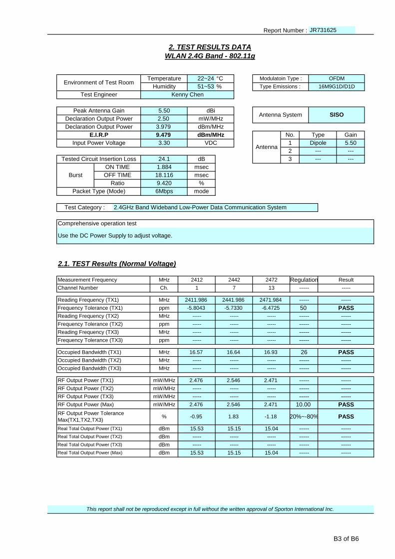
2. TEST RESULTS DATA
WLAN 2.4G Band - 802.11g
Environment of Test RoomTemperature 22~24 °C Modulatoin Type : OFDM
Humidity 51~53
Declaration Output Power 2.50 mW/MHz
Declaration Output Power 3.979 dBm/MHz
% Type Emissions : 16M9G1D/D1D
Test Engineer Kenny Chen
Peak Antenna Gain 5.50 dBiAntenna System SISO
---
Tested Circuit Insertion Loss 24.1 dB 3 --- ---
Gain
Input Power Voltage 3.30 VDC 1 Dipole 5.50
E.I.R.P 9.479 dBm/MHz
Antenna
No. Type
2 ---
Packet Type (Mode) 6Mbps mode
Test Category : 2.4GHz Band Wideband Low-Power Data Communication System
Comprehensive operation test
Burst
ON TIME 1.884 msec
OFF TIME 18.116 msec
Ratio 9.420 %
Use the DC Power Supply to adjust voltage.
2.1. TEST Results (Normal Voltage)
Measurement Frequency MHz 2412 2442 2472 Regulation Result
-----
Reading Frequency (TX1) MHz 2411.986 2441.986 2471.984
Channel Number Ch. 1 7 13 -----
----- -----
Frequency Tolerance (TX1) ppm -5.8043 -5.7330 -6.4725 50 PASS
-----
Frequency Tolerance (TX2) ppm ----- ----- ----- ----- -----
Reading Frequency (TX2) MHz ----- ----- ----- -----
-----
Frequency Tolerance (TX3) ppm ----- ----- ----- ----- -----
Reading Frequency (TX3) MHz ----- ----- ----- -----
PASS
Occupied Bandwidth (TX2) MHz ----- ----- ----- ----- -----
Occupied Bandwidth (TX1) MHz 16.57 16.64 16.93 26
-----
RF Output Power (TX1) mW/MHz 2.476 2.546 2.471 ----- -----
Occupied Bandwidth (TX3) MHz ----- ----- ----- -----
-----
RF Output Power (TX3) mW/MHz ----- ----- ----- ----- -----
RF Output Power (TX2) mW/MHz ----- ----- ----- -----
PASS
RF Output Power Tolerance
Max(TX1,TX2,TX3)% -0.95 1.83 -1.18 20%~-80% PASS
RF Output Power (Max) mW/MHz 2.476 2.546 2.471 10.00
Real Total Output Power (TX1) dBm 15.53 15.15 15.04 ----- -----
-----
Real Total Output Power (TX3) dBm ----- ----- ----- ----- -----
Real Total Output Power (TX2) dBm ----- ----- ----- -----
-----
This report shall not be reproduced except in full without the written approval of Sporton International Inc.
Real Total Output Power (Max) dBm 15.53 15.15 15.04 -----
B3 of B6

Report Number : JR731625
2.1. TEST Results (Normal Voltage)
Measurement Frequency MHz 2412 2442 2472 Regulation Result
Channel Number Ch. 1 7 13 ----- -----
2.5 PASS
MHz 2386.653 2357.541 2373.484 ----- -----Unwanted
Emission
Strength
(TX1) for
Ch1 ~13
Under 2387MHz μW/MHz 0.179061 0.048641 0.066069
2387-2400MHzμW/MHz 4.064433 0.070307 0.091411 25 PASS
MHz 2399.893 2399.769 2398.386 ----- -----
PASS
MHz 2489.857 2492.534 2483.711 ----- -----2483.5-2496.5MHz
μW/MHz 0.118850 0.060814 3.630781 25
PASS
MHz 6752.064 6585.022 2497.000 ----- -----2496.5MHz-12.5GHz
μW/MHz 0.046345 0.048306 0.144544 2.5
----- -----
MHz ----- ----- ----- ----- -----Unwanted
Emission
Strength
(TX2) for
Ch1 ~ 13
Under 2387MHz μW/MHz ----- ----- -----
2387-2400MHzμW/MHz ----- ----- ----- ----- -----
MHz ----- ----- ----- ----- -----
-----
MHz ----- ----- ----- ----- -----2483.5-2496.5MHz
μW/MHz ----- ----- ----- -----
-----
MHz ----- ----- ----- ----- -----2496.5MHz-12.5GHz
μW/MHz ----- ----- ----- -----
----- -----
MHz ----- ----- ----- ----- -----Unwanted
Emission
Strength
(TX3) for
Ch1 ~ 13
Under 2387MHz μW/MHz ----- ----- -----
2387-2400MHzμW/MHz ----- ----- ----- ----- -----
MHz ----- ----- ----- ----- -----
-----
MHz ----- ----- ----- ----- -----2483.5-2496.5MHz
μW/MHz ----- ----- ----- -----
-----
MHz ----- ----- ----- ----- -----2496.5MHz-12.5GHz
μW/MHz ----- ----- ----- -----
----- -----
MHz ----- ----- ----- ----- -----
Unwanted
Emission
Strength
(TX1+2) or
(TX1+2+3) for
Ch1 ~13
Under 2387MHz μW/MHz ----- ----- -----
2387-2400MHzμW/MHz ----- ----- ----- ----- -----
MHz ----- ----- ----- ----- -----
-----
MHz ----- ----- ----- ----- -----2483.5-2496.5MHz
μW/MHz ----- ----- ----- -----
-----
MHz ----- ----- ----- ----- -----2496.5MHz-12.5GHz
μW/MHz ----- ----- ----- -----
Secondarily
Emitted Radio
Wave Strength
(RX Spurious)
(RX1)
Under 1GHznW 0.030903 0.020941 0.021928 4 PASS
MHz 931.767 747.195 759.998 ----- -----
It should be added up all spurious measurement values within "Reference Bandwidth(=1MHz)" of the same frequency.
PASS
MHz 6999.146 6627.344 6768.207 ----- -----1 - 12.5GHz
nW 0.282488 0.337287 0.281838 20
----- -----
MHz ----- ----- ----- ----- -----
Secondarily
Emitted Radio
Wave Strength
(RX Spurious)
(RX2)
Under 1GHznW ----- ----- -----
1 - 12.5GHznW ----- ----- ----- ----- -----
MHz ----- ----- ----- ----- -----
----- -----
MHz ----- ----- ----- ----- -----
Secondarily
Emitted Radio
Wave Strength
(RX Spurious)
(RX3)
Under 1GHznW ----- ----- -----
1 - 12.5GHznW ----- ----- ----- ----- -----
MHz ----- ----- ----- ----- -----
----- -----
----- -----
Secondarily
Emitted Radio
Wave Strength
(RX Spurious)
(RX1+2) or
(RX1+2+3)
Under 1GHznW ----- ----- -----
1 - 12.5GHznW ----- ----- ----- ----- -----
----- -----
This report shall not be reproduced except in full without the written approval of Sporton International Inc.
It should be added up all spurious measurement values within "Reference Bandwidth(=1MHz)" of the same frequency.
Interference Prevention Function ----- good ----- PASS
B4 of B6

Report Number : JR731625
3. TEST RESULTS DATA
WLAN 2.4G Band - 802.11n-HT20
Environment of Test RoomTemperature 22~24 °C Modulatoin Type : OFDM
Humidity 51~53
Declaration Output Power 2.50 mW/MHz
Declaration Output Power 3.979 dBm/MHz
% Type Emissions : 18M2G1D/D1D
Test Engineer Kenny Chen
Peak Antenna Gain 5.50 dBiAntenna System SISO
---
Tested Circuit Insertion Loss 24.1 dB 3 --- ---
Gain
Input Power Voltage 3.30 VDC 1 Dipole 5.50
E.I.R.P 9.479 dBm/MHz
Antenna
No. Type
2 ---
Packet Type (Mode) MCS0 mode
Test Category : 2.4GHz Band Wideband Low-Power Data Communication System
Comprehensive operation test
Burst
ON TIME 1.761 msec
OFF TIME 18.313 msec
Ratio 8.773 %
Use the DC Power Supply to adjust voltage.
3.1. TEST Results (Normal Voltage)
Measurement Frequency MHz 2412 2442 2472 Regulation Result
-----
Reading Frequency (TX1) MHz 2411.984 2441.987 2471.984
Channel Number Ch. 1 7 13 -----
----- -----
Frequency Tolerance (TX1) ppm -6.6335 -5.3235 -6.4725 50 PASS
-----
Frequency Tolerance (TX2) ppm ----- ----- ----- ----- -----
Reading Frequency (TX2) MHz ----- ----- ----- -----
-----
Frequency Tolerance (TX3) ppm ----- ----- ----- ----- -----
Reading Frequency (TX3) MHz ----- ----- ----- -----
Occupied Bandwidth (TX1) MHz 17.87 18.16 17.80 26 PASS
Occupied Bandwidth (TX2) MHz ----- ----- ----- ----- -----
-----
RF Output Power (TX1) mW/MHz 2.221 2.246 2.076 ----- -----
Occupied Bandwidth (TX3) MHz ----- ----- ----- -----
-----
RF Output Power (TX3) mW/MHz ----- ----- ----- ----- -----
RF Output Power (TX2) mW/MHz ----- ----- ----- -----
PASS
RF Output Power Tolerance
Max(TX1,TX2,TX3)% -11.17 -10.16 -16.96 20%~-80% PASS
RF Output Power (Max) mW/MHz 2.221 2.246 2.076 10.00
Real Total Output Power (TX1) dBm 15.52 15.16 14.63 ----- -----
-----
Real Total Output Power (TX3) dBm ----- ----- ----- ----- -----
Real Total Output Power (TX2) dBm ----- ----- ----- -----
-----
This report shall not be reproduced except in full without the written approval of Sporton International Inc.
Real Total Output Power (Max) dBm 15.52 15.16 14.63 -----
B5 of B6

Report Number : JR731625
3.1. TEST Results (Normal Voltage)
Measurement Frequency MHz 2412 2442 2472 Regulation Result
Channel Number Ch. 1 7 13 ----- -----
2.5 PASS
MHz 2386.653 2358.234 2355.462 ----- -----Unwanted
Emission
Strength
(TX1) for
Ch1 ~13
Under 2387MHz μW/MHz 0.260615 0.055208 0.046559
2387-2400MHzμW/MHz 2.055891 0.058345 0.068865 25 PASS
MHz 2399.302 2398.282 2399.276 ----- -----
PASS
MHz 2487.525 2488.850 2483.672 ----- -----2483.5-2496.5MHz
μW/MHz 0.082414 0.067143 1.584893 25
PASS
MHz 6851.088 6827.082 2497.000 ----- -----2496.5MHz-12.5GHz
μW/MHz 0.051168 0.052000 0.069663 2.5
----- -----
MHz ----- ----- ----- ----- -----Unwanted
Emission
Strength
(TX2) for
Ch1 ~ 13
Under 2387MHz μW/MHz ----- ----- -----
2387-2400MHzμW/MHz ----- ----- ----- ----- -----
MHz ----- ----- ----- ----- -----
-----
MHz ----- ----- ----- ----- -----2483.5-2496.5MHz
μW/MHz ----- ----- ----- -----
-----
MHz ----- ----- ----- ----- -----2496.5MHz-12.5GHz
μW/MHz ----- ----- ----- -----
----- -----
MHz ----- ----- ----- ----- -----Unwanted
Emission
Strength
(TX3) for
Ch1 ~ 13
Under 2387MHz μW/MHz ----- ----- -----
2387-2400MHzμW/MHz ----- ----- ----- ----- -----
MHz ----- ----- ----- ----- -----
-----
MHz ----- ----- ----- ----- -----2483.5-2496.5MHz
μW/MHz ----- ----- ----- -----
-----
MHz ----- ----- ----- ----- -----2496.5MHz-12.5GHz
μW/MHz ----- ----- ----- -----
----- -----
MHz ----- ----- ----- ----- -----
Unwanted
Emission
Strength
(TX1+2) or
(TX1+2+3) for
Ch1 ~13
Under 2387MHz μW/MHz ----- ----- -----
2387-2400MHzμW/MHz ----- ----- ----- ----- -----
MHz ----- ----- ----- ----- -----
-----
MHz ----- ----- ----- ----- -----2483.5-2496.5MHz
μW/MHz ----- ----- ----- -----
-----
MHz ----- ----- ----- -----2496.5MHz-12.5GHz
μW/MHz ----- ----- ----- -----
Secondarily
Emitted Radio
Wave Strength
(RX Spurious)
(RX1)
Under 1GHznW 0.019320 0.023878 0.021727 4 PASS
MHz 978.129 668.245 972.018 ----- -----
It should be added up all spurious measurement values within "Reference Bandwidth(=1MHz)" of the same frequency.
PASS
MHz 6634.051 6596.679 6997.229 ----- -----1 - 12.5GHz
nW 0.292415 0.287740 0.321366 20
----- -----
MHz ----- ----- ----- ----- -----
Secondarily
Emitted Radio
Wave Strength
(RX Spurious)
(RX2)
Under 1GHznW ----- ----- -----
1 - 12.5GHznW ----- ----- ----- ----- -----
MHz ----- ----- ----- ----- -----
----- -----
MHz ----- ----- ----- ----- -----
Secondarily
Emitted Radio
Wave Strength
(RX Spurious)
(RX3)
Under 1GHznW ----- ----- -----
1 - 12.5GHznW ----- ----- ----- ----- -----
MHz ----- ----- ----- ----- -----
----- -----
----- -----
Secondarily
Emitted Radio
Wave Strength
(RX Spurious)
(RX1+2) or
(RX1+2+3)
Under 1GHznW ----- ----- -----
1 - 12.5GHznW ----- ----- ----- ----- -----
----- -----
This report shall not be reproduced except in full without the written approval of Sporton International Inc.
It should be added up all spurious measurement values within "Reference Bandwidth(=1MHz)" of the same frequency.
Interference Prevention Function ----- good ----- PASS
B6 of B6

SPORTON INTERNATIONAL INC. Page Number : C1 of C6
TEL : 886-3-327-3456
FAX : 886-3-328-4978
JAPAN Radio Test Report – WLAN 2.4GHz Band Report No. : JR731625
Appendix C. Test Plots
C.1. 2.4GHz Band_NV
C.1.1. 802.11b
i. Frequency Tolerance
Low Channel Middle Channel High Channel
Antenna 1
ii. Occupied Bandwidth and Spread-spectrum Bandwidth
Occupied Bandwidth
Low Channel Middle Channel High Channel
Antenna 1
Spread-spectrum Bandwidth
Low Channel Middle Channel High Channel
Antenna 1

SPORTON INTERNATIONAL INC. Page Number : C2 of C6
TEL : 886-3-327-3456
FAX : 886-3-328-4978
JAPAN Radio Test Report – WLAN 2.4GHz Band Report No. : JR731625
iii. Unwanted Emission Intensity
Low Channel Middle Channel High Channel
Antenna 1
iv. Limitation of Collateral Emission of Receiver
Low Channel Middle Channel High Channel
Antenna 1
SPORTON INTERNATIONAL INC. Page Number : C3 of C6
TEL : 886-3-327-3456
FAX : 886-3-328-4978
JAPAN Radio Test Report – WLAN 2.4GHz Band Report No. : JR731625
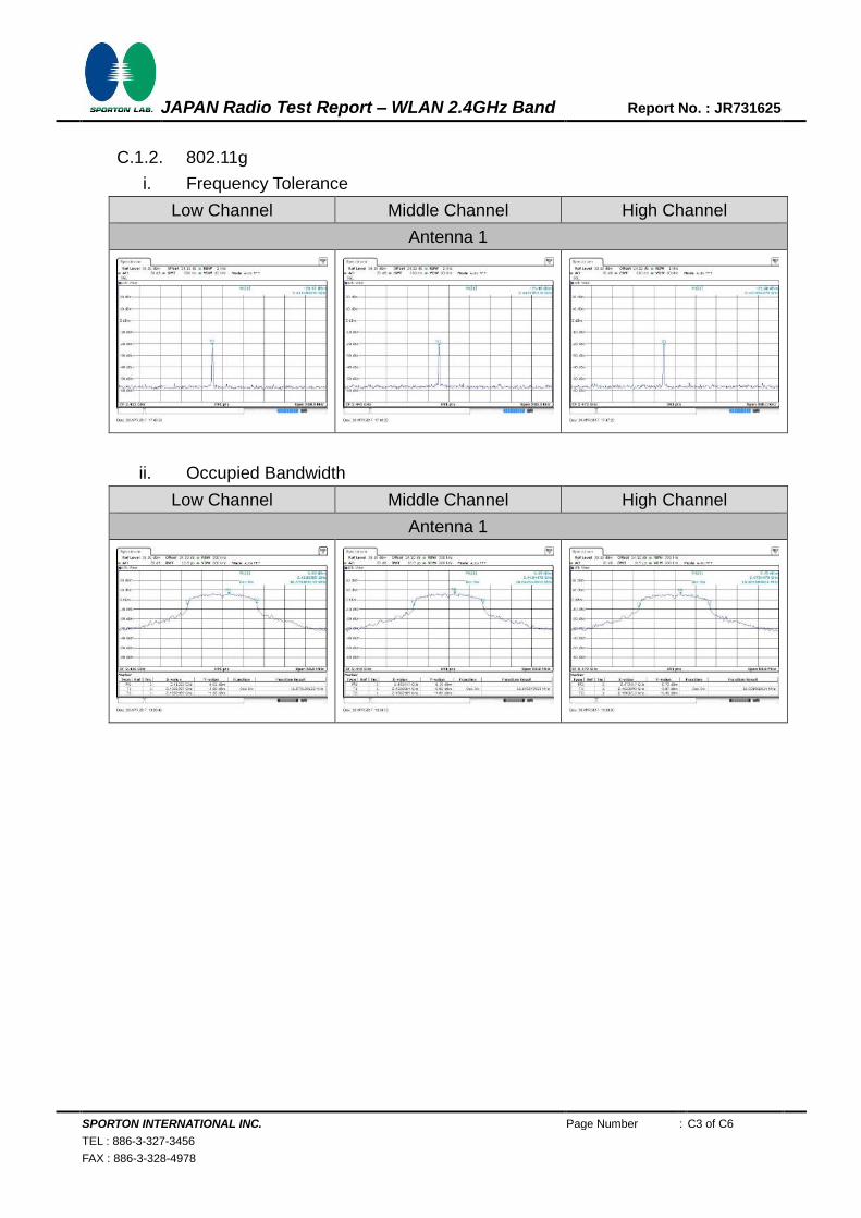
C.1.2. 802.11g
i. Frequency Tolerance
Low Channel Middle Channel High Channel
Antenna 1
ii. Occupied Bandwidth
Low Channel Middle Channel High Channel
Antenna 1

SPORTON INTERNATIONAL INC. Page Number : C4 of C6
TEL : 886-3-327-3456
FAX : 886-3-328-4978
JAPAN Radio Test Report – WLAN 2.4GHz Band Report No. : JR731625
iii. Unwanted Emission Intensity
Low Channel Middle Channel High Channel
Antenna 1
Note : The spurious emission which exceed limit was re-measured by setting zero span in the spectrum analyzer shown as below plot.
N/A
iv. Limitation of Collateral Emission of Receiver
Low Channel Middle Channel High Channel
Antenna 1
SPORTON INTERNATIONAL INC. Page Number : C5 of C6
TEL : 886-3-327-3456
FAX : 886-3-328-4978
JAPAN Radio Test Report – WLAN 2.4GHz Band Report No. : JR731625
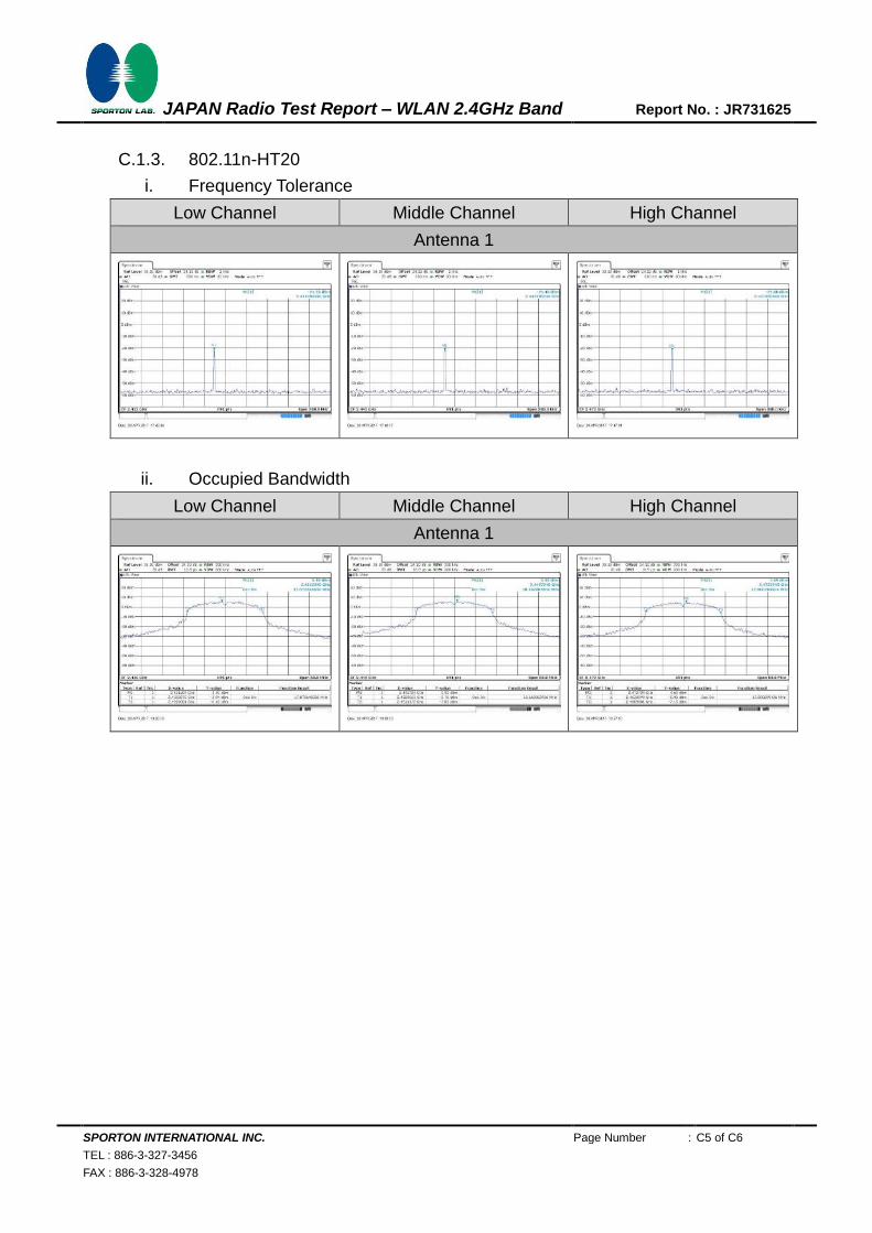
C.1.3. 802.11n-HT20
i. Frequency Tolerance
Low Channel Middle Channel High Channel
Antenna 1
ii. Occupied Bandwidth
Low Channel Middle Channel High Channel
Antenna 1

SPORTON INTERNATIONAL INC. Page Number : C6 of C6
TEL : 886-3-327-3456
FAX : 886-3-328-4978
JAPAN Radio Test Report – WLAN 2.4GHz Band Report No. : JR731625
iii. Unwanted Emission Intensity
Low Channel Middle Channel High Channel
Antenna 1
Note : The spurious emission which exceed limit was re-measured by setting zero span in the spectrum analyzer shown as below plot.
N/A
iv. Limitation of Collateral Emission of Receiver
Low Channel Middle Channel High Channel
Antenna 1