january 2015 making progress in 2015
TRANSCRIPT

www.augiworld.com US $8.00
Making Progress in
2015
January 2015
AUGIWorldT h e O f f i c i a l P u b l i c a t i o n o f A u t o d e s k U s e r G r o u p I n t e r n a t i o n a l
Diamond Sponsors
Also in This Issue
• Hidden Gems for Surveyors
• Design-Level BIM
• Transitioning from AutoCAD to Revit

© 2015 Hewlett-Packard Company, L.P. The information contained herein is subject to change without notice.1The HP Z230 SFF Workstation is certified for AutoCAD 2015. 2Units shipped based on IDC Quarterly Worldwide Workstation Tracker Q2 CY2014. 3Based on the white paper, AutoCAD 2015 Performance: HP Z230 Workstation vs. HP PC. Autodesk was not involved in testing; this does not constitute an endorsement of these claims by Autodesk. NVIDIA, the NVIDIA logo and Quadro are registered trademarks and/or trademarks of NVIDIA Corporation in the United States and other countries. Autodesk and AutoCAD are registered trademarks or trademarks of Autodesk, Inc.,and/or its subsidiaries and/or affiliates in the USA and other countries. All other trademarks are the property of their respective owners.
HP can deliver up to:59% faster modeling 40% faster rendering 95% better overall performance3
Make your AutoCAD® performance more awesome with
HP recommends Windows.
Z It’s time to move up to an AutoCAD 2015 certified, affordably priced Z Workstation from HP.1 Featuring next-gen processors and professional graphics technologies, Z Workstations are specifically designed to handle today’s most complex modeling and rendering projects. Add in our three-year warranty and experience HP’s ultimate combination of performance and value. Find out what makes HP Z Workstations the world’s #1 workstation brand.2 Learn more at hp.com/go/autocad

AUGIWorld JAN
UA
RY
2015
contentsproduct focus
28
January 2015 www.augi.com 3
columns4 Letter from the President
8 Technology in Practice, with CASE & HP
12 AUGI Wish List 2014
18
16 Product Review: MSI WS60: An Autodesk-Worthy Laptop
39 Inside Track
36
Cover image: Miami Marlins Stadium, Miami, Florida, USA. Photo
Copyright© 2012 - David Harrington. Reuse of full or partial copyright image, in any form, without prior
written permission is strictly prohibited.
40
6 CAD Manager: And Now a Word from Our Sponsor
10 AutoCAD 2015: Work on Your Personal Advancement
18 Revit MEP: Trial, Error, Success
24 AutoCAD Architecture 2015: Speed and Simplify with Sheet Set Manager
28 AutoCAD Civil 3D 2015: Hidden Survey Gems
33 BIM Construction: Design-Level BIM
36 Inventor 2015: 10 Reasons Why Inventor Is Still My Sweetheart
40 Revit Structure: Real Life Perspective: Transitioning from AutoCAD to Revit

Letter from the President
4 www.augi.com January 2015
JAN
UA
RY
201
5
www.augiworld.com
EditorsEditor-in-ChiefDavid Harrington - [email protected]
Copy EditorMarilyn Law - [email protected]
Layout EditorDebby Gwaltney - [email protected]
Content Managers 3ds Max - Brian ChapmanAutoCAD - Walt SparlingAutoCAD Architecture - Melinda HeavrinAutoCAD Civil 3D - Shawn HerringAutoCAD MEP - William CampbellBIM Construction - Kenny EastmanCAD Manager - Mark KikerInside Track - Brian AndresenInventor - John EvansNavisworks - Michael SmithRevit Architecture - Jay ZallanRevit MEP - Todd ShackelfordRevit Structure -Kimberly Fuhrman
Advertising / Reprint SalesKevin Merritt - [email protected]
AUGI Management President R. Robert Bell
Vice Presidents Scott Wilcox
TreasurerWalt Sparling
SecretaryMichael Smith
ManagementKevin Merritt - Director of CommunicationsJuly Ratley - Director of FinanceDavid Harrington - Director of Operations
AUGI Board of DirectorsR. Robert BellShaun BryantChris LindnerCurt MorenoKate Morrical
Melanie PerryMichael SmithWalt SparlingScott Wilcox
Publication InformationAUGIWorld magazine is a benefit of specific AUGI membership plans. Direct magazine subscriptions are not available. Please visit http://www.augi.com/account/register to join or upgrade your membership to receive AUGIWorld magazine in print. To manage your AUGI membership and address, please visit http://www.augi.com/account . For all other magazine inquires please contact [email protected]
Published by: AUGIWorld is published by Autodesk User Group Inter-national, Inc. AUGI makes no warranty for the use of its products and assumes no responsibility for any errors which may appear in this publication nor does it make a commitment to update the information contained herein.
AUGIWorld is Copyright ©2015 AUGI. No informa-tion in this magazine may be reproduced without expressed written permission from AUGI.
All registered trademarks and trademarks included in this magazine are held by their respective companies. Every attempt was made to include all trademarks and regis-tered trademarks where indicated by their companies.
AUGIWorld (San Francisco, Calif.)ISSN 2163-7547
A GREAT AUTODESK UNIVERSITY FOR AUGI
I write this letter while still recovering from this year’s Autodesk University. No, it’s not what you think... I didn’t stay up too late at night nor did I overindulge. You see, this was my first year attending Autodesk University as the president of AUGI. And let me tell you, there is a lot that goes on.
I did present one class. Thankfully, it was only one class! Those who know me well can remember when I would present four to six classes year after year. Those days are behind me now as I focus more on AUGI while at AU.
There were many highlights for AUGI this year at AU.
Our booth was as popular as ever. There was great participation in both the Top DAUG contest and the AUGI Scavenger Hunt. The overall winner of the Top DAUG contest was Tracy Chadwick and the winner of the AUGI Scavenger Hunt was Ashley Otomo. Congratulations to both winners of a free pass to Autodesk University 2015!
Another highlight for AUGI this year was the Annual Meeting held on Wednesday. I would personally like to thank Ignite Shanbaky of Autodesk for providing AUGI with a professional venue and excellent AV support for the meeting.
The meeting was lively and fun and even included an appearance by the AutoCAD Genie, played by the willing victim, er, volunteer Shaan Hurley of Autodesk. My first two AutoCAD wishes, intentionally selected, were already granted in prior releases. But my third wish, the actual #1 wish this year, has not yet been granted (only time will tell if it makes it into the next release). The skit between Shaan and I was a fun way to show that AUGI’s Wish List system is a valuable resource for Autodesk and that our wishes do come true. This year’s Wish List participation was much higher than last year’s, so keep up the good work.
We presented the top wish for each of the products we have in the Wish List system, which was sponsored by HP|Intel this year. Don’t forget to check your AUGI profile and make sure the products you use are selected in your profile. This is the only way you can participate in the AUGI Wish List.
We gave away a free pass to next year’s Autodesk University to one lucky attendee at the Annual Meeting, Kurt Tolliver. We also surprised people who arrived early to the meet-ing with AUGI-branded items.
At the Annual Meeting we recognized our benefactors for the year: Autodesk (Olivier Le Pord), HP (Sean Young), and Dell (Andy Rhodes).
We wrapped up the Annual Meeting by sending everyone out the door with a beer mug to be filled with whatever refreshing beverage they wanted at the AUGI Reception held in the exhibit hall immediately after the meeting.
There were many other things going on at this year’s AU—too many to list here. But hopefully reading about the great things that went on at the event will inspire you to attend next year!
R. Robert BellAUGI President
AUGIWorld
Autodesk, AutoCAD, Autodesk Architectural Desktop, Autodesk Revit, Autodesk Building Systems, Autodesk Civil Design, Autodesk In-ventor and DWF are either registered trademarks or trademarks of Autodesk, Inc. in the U.S.A. and/or in certain other countries. All other brand names, product names, or trademarks belong to their respective holders.

bim arcat.combim arcat.com
Free to use, no registration required
arcat.combim it
Thousands of BIM objects and systems
Available in multiple formats
BIM@ Ad.indd 1 10/6/2014 3:58:39 PM

6 www.augi.com January 2015
CAD ManagerC
OL
UM
Nby: Mark Kiker
6 www.augi.com January 2015
These words, spoken so well for so many years by Alfred Hitchcock on TV, were usually delivered in a slightly sarcastic, tongue-in-cheek manner. Then the show
would cut away to commercials. This article is not a commercial interruption, but rather an encouragement to help others.
According to Sylvia Ann Hewlett of the Center for Talent Innova-tion, leaders who sponsor talented individuals in their companies end up more successful in their careers.
Most of us understand mentoring at some level. The wise one passes on knowledge to the student—kind of like Obi-Wan Kenobi and Luke Skywalker. The Master passes wisdom on to the young Padawan.
What some may not realize is that mentoring engages two differ-ent functions: sponsor and mentor. The function of the sponsor is similar to that of the mentor but goes beyond it. Mentors may think of themselves as teachers or professors—they pass out wis-dom and knowledge, but have little stake in the game. If the pro-tégé does not “get it,” or take the advice or improve, then there is little negative impact on the mentor other than frustration.
And Now a Word
from Our Sponsor

January 2015 www.augiworld.com 7January 2015 www.augiworld.com 7
CAD Manager CO
LU
MN
Mark Kiker has more than 25 years of hands-on experience with technol-ogy. He is fully versed in every area of management from deployment plan-ning, installation, and configuration to training and strategic planning. As an internationally known speaker and writer, he is a returning speaker at Autodesk University since 1996. Mark is currently serving as Direc-tor of IT for SIATech, a non-profit public charter high school focused on dropout recovery. He maintains two blog sites, www.caddmanager.com and www.bimmanager.com .
The mentoring functions call for close interaction the protégé. Mentors teach protégés the ropes—the trade and the tools of that trade. Mentors serve as positive role models that protégés can watch and observe. Mentors help build the self-esteem, fortitude, resilience, and stamina of the protégé. They come alongside the protégé and demonstrate the use and application of knowledge in order to produce wisdom.
The sponsor, on the other hand, extends the wisdom and knowledge, but also has a personal stake in the outcome of the protégé’s progress. Sponsors and protégés are tied closely together. If one succeeds, the other does also. If the protégé stumbles, the sponsor may hear criticism and be regarded as one who cannot choose or grow talent.
A sponsor would be an advocate for the promotion of the protégé. The sponsor would offer the protégé up as the perfect fit to lead the next project or the proper selection for a critical assignment. They would nudge oth-ers to support the efforts of the pro-tégé and seek to lift them up to the next rung of the career ladder. It is a combination of mentor and coach. The sponsor is an encourager who gives advice and promotes the work of the protégé.
The sponsor also connects the protégé with the right people in the firm. Sponsors offer tips on succeeding with senior staff and pass on clues to avoid political pitfalls. They will step in to avert difficult situations between an executive and the protégé, seeking to have both sides fully understand the issues and seek agreement.
The benefits to the protégé are often very obvious. Protégés that have consistent input from a mentor or sponsor show bet-ter job performance. They are more likely to help others, have greater job satisfaction, and have a positive perspective on the future. They are more motivated, have career goals, and re-ceived assistance in reaching these goals.
There are also benefits for the mentor/sponsor. They connect with talented staff that provides a bridge of understanding into new ideas, updated technology, and project methods. The pro-tégé keeps the mentor connected to the front lines of CAD and BIM projects. The protégé brings unique ideas that the mentor can spread throughout the company. The protégé can expand the sponsor’s breadth of knowledge and be a go-to person for specific technical wisdom. The protégé can be a lifeline into another department and extend the reach of the sponsor’s ef-forts. Just as the sponsor promotes and protects the protégé, they return the support and protect their sponsor from blind spots that they sponsor may not be aware of. The protégé can be the eyes and ears that uncover the telltale signs of a project going off track or a guideline being ignored.
The mentor/sponsor also garners personal fulfillment through contributing to the protégé. They get the satisfaction of help-ing another and shaping the future of the firm and the industry. They develop talent, which makes their company stronger and sets a career in motion.
Anyone who has attended one of my Autodesk University pre-sentations knows that I end each class with a final slide: the appeal to “Pass It On.” One of the best ways to pass on informa-tion, ideas, advice, and more is to do it through the individual you are counseling. Pouring yourself into others is enriching.
Some firms have formal programs to encourage the connection between a mentor and a protégé. I have been involved in some of
these programs from both sides—that of mentor and protégé. Unfortunately, many of these programs seem con-trived and are so structured that they become deflating rather than platforms that enabled people to soar.
I now encourage personal mentoring, which can be tailored to exactly what might be needed in an early or even mid-career staffer. Connecting sea-soned employees with those coming up the ranks can provide enriching interactions. By having some formal
and informal processes in place, you can impact someone in such a positive way that you may soon seek more of these kinds of relationships.
Over the next few months, I will unpack this concept and discuss how the process might work from both the mentor/sponsor and the protégé perspectives. By connecting seasoned industry veterans with emerging talent, we can all help the De-sign, Manufacturing, Entertainment, CAD, and BIM indus-tries grow strong.
[ ]The wise one passes
on knowledge to
the student—kind of
like Obi-Wan Kenobi
and Luke Skywalker.
The Master passes on
wisdom to the young
Padawan.

Tech Insights Tech
nolog
y in P
ractice, with
CA
SE &
HP
Tech InsightsT
ech
nol
ogy
in P
ract
ice,
wit
h C
ASE
& H
P
multiple offices struggling to keep everyone in sync or for firms that have remote workers who are unable to sync large files. And since the files are stored on servers or centralized storage infrastructure rather than laptops and memory sticks, there is less risk of project data being stolen, which is an important consideration for firms working on sensitive governmental projects.
Virtualization does have its drawbacks, particularly if you have a slow or intermittent connection back to the server. For virtualization to feel natural, the network latency needs to be below 150ms and ideally around 70ms. On a local network this shouldn’t be a problem provided you have gigabit Ethernet. However, if the workstation is being operated outside the local network, you may require a MPLS connection to ensure the least latency.
Employees also need a period to adjust to virtualization. For those accustomed to PCs, the fact that their files and computing power don’t reside locally can be slightly difficult to grasp. In most circumstances this shouldn’t be a problem provided the change from PCs to virtualized infrastructure is managed and communicated well.
The virTualizaTion sTackVirtualization requires a combination of software and hardware. There are four main components to the software powering virtualization:
1. The Hypervisor hosts and provides resources for virtual machines.
2. The virtual desktop management software manages the deployment of the virtual machines to the users.
3. The sending agent creates and sends data from the server to the user.
4. The receiving agent renders the desktop on a client access device, such as a laptop or thin client.
The two main providers of virtualization software are Citrix® and VMware®.
On the hardware side, you need a server to run the virtual machine and a client for the user to interact with. Since the client machine is only displaying the desktop and sending the user input, it can be relatively lightweight. It could even be a tablet if you are travelling. Although if you are working at your desk you probably want to go with either an HP ZBook 14 Mobile Workstation or an HP t620 Flexible Thin Client.
The server should be highly spec’d. Remember that you are essentially splitting the cost of this server across the number of users accessing it. Therefore, the server should have a fast processor—like an Intel® Xeon® processor—because Revit loves GHz. It should also have plenty of CPU cores in order
to maximize the number of users. Also, get as much RAM as possible, since you will be running multiple instances of the same program from one server. The number of GPUs and the way they are distributed to the virtual machines is another important consideration, particularly for 3d applications.
The HP DL380p server has been specifically optimized to support high-end 3d graphics software. These servers also feature a choice of the latest Intel Xeon E5-2600 v3 CPUs (up to 18 cores each), up to 1.5TB of 2,133 MHz, DDR4 memory, and a choice of NVIDIA® GPUs, including up to two NVIDIA GRID™ K2s (8 GB each). It can also support up to ten 2.5-inch drives internally and boasts 10 Gigabit Ethernet for a high-speed connection to shared data center storage. HP servers have been designed to support Citrix and VMware software with HP’s software for remotely administering virtualized workstations and monitoring performance.
abouT hPHP helps you stay ahead of the curve with professional desktop and mobile workstations designed for large and complex datasets, dispersed teams, and tight deadlines. HP Z Workstations built for Pros with Intel Inside® deliver the innovation, high performance, expandability, and extreme reliability you need to deliver your 3D CAD projects in less time. To learn how to configure a HP Z Workstation, visit the HP and Autodesk Page at (www.hp.com/go/autodeskmanufacturing). Start saving now!
abouT caseCASE exists where building and technology intersect. We combine our experience as architects, engineers, project managers, software developers, and educators with a passion for technology to improve the way buildings are designed, realized, and operated. CASE is a building information modeling (BIM) and integrated-practice consultancy. We provide strategic advising to building design professionals, contractors, and owners seeking to supplant traditional project delivery methods through technology-driven process innovation.
becoming virtualized: the future of computation in the aec industry
The advent of the personal computer (PC) in the 1980s carried with it the intrinsic message that every individual should possess their own “personal”
computer. This type of independent ownership made sense at a time when computers were used primarily by individuals working in isolation. But today, with people in the AEC industry working remotely and together, it seems like an anachronism to suggest that they need to be physically at their own PC in order to get their work done.
With the advent of low-latency, high-bandwidth network connections, and a range of new hardware and software designed for virtualization, a number of AEC firms are moving away from PCs to a virtualized computing environment. Many more firms are testing the feasibility of this approach, with virtualization looking set to become a lasting trend in the industry. In this article, we look at the key considerations for firms moving to a virtualized environment and suggest a range of hardware configurations to make the most of virtualization.
considering virTualizaTion Generally speaking, you can think of virtualization as a way to use the internet as an extension cord for your keyboard and monitor. You don’t need to be beside a virtualized computer to use it. The workstation might be in another room, receiving your keyboard and mouse commands via the local network and returning with what needs to be displayed on the monitor. The workstation might even be in a different city or in another country. Provided the network has sufficient capacity and a low latency, operating a computer virtually can feel as fluid as operating one locally.
This makes virtualization a compelling solution for AEC firms that increasingly need to accommodate a highly mobile
workforce. Instead of carrying a powerful laptop, employees can carry a lightweight Ultrabook™ (or even a tablet) while still having access to the performance of a high-end workstation.
Another advantage of virtualization is that computing resources can be consolidated. Rather than every employee having an individual workstation, there may be as many as 16 people working from a single server. These virtual computers can be tailored to each individual. Users doing basic tasks can be assigned fewer resources in order to free up even more computing power for other users. Some firms are also experimenting with a hybrid virtualization setup, whereby users have their own individual workstation for their most common tasks, but also have access to high-performance virtualized servers for when they need to do computationally intensive tasks such as rendering, clash detection, and point cloud processing.
Since the virtualized workstations can be hosted together in a datacenter, file transfer between workstations and from central storage is extremely fast. Users don’t need to sync files to their local machines, but can instead work on files directly from the server. This can make a huge difference for firms that have
➲
© 2015 Hewlett-Packard Development Company, L.P. The information contained herein is subject to change without notice. The only warranties for HP products and services are set forth in the express warranty statements accompanying such products and services. Nothing herein should be construed as constituting an additional warranty. HP shall not be liable for technical or editorial errors or omissions contained herein. Intel, Xeon and Ultrabook are trademarks of Intel Corporation in the U.S. and other countries. NVIDIA and Grid are trademarks and/or registered trademarks of NVIDIA Corporation in the U.S. and other countries. Citrix® is a registered trademark of Citrix Systems, Inc. and/or one more of its subsidiaries, and may be registered in the United States Patent and Trademark Office and in other countries. Screen Image Courtesy of Autodesk.
8 www.augi.com January 2015

Tech Insights Tech
nolog
y in P
ractice, with
CA
SE &
HP
Tech Insights
Tec
hn
olog
y in
Pra
ctic
e, w
ith
CA
SE &
HP
multiple offices struggling to keep everyone in sync or for firms that have remote workers who are unable to sync large files. And since the files are stored on servers or centralized storage infrastructure rather than laptops and memory sticks, there is less risk of project data being stolen, which is an important consideration for firms working on sensitive governmental projects.
Virtualization does have its drawbacks, particularly if you have a slow or intermittent connection back to the server. For virtualization to feel natural, the network latency needs to be below 150ms and ideally around 70ms. On a local network this shouldn’t be a problem provided you have gigabit Ethernet. However, if the workstation is being operated outside the local network, you may require a MPLS connection to ensure the least latency.
Employees also need a period to adjust to virtualization. For those accustomed to PCs, the fact that their files and computing power don’t reside locally can be slightly difficult to grasp. In most circumstances this shouldn’t be a problem provided the change from PCs to virtualized infrastructure is managed and communicated well.
The virTualizaTion sTackVirtualization requires a combination of software and hardware. There are four main components to the software powering virtualization:
1. The Hypervisor hosts and provides resources for virtual machines.
2. The virtual desktop management software manages the deployment of the virtual machines to the users.
3. The sending agent creates and sends data from the server to the user.
4. The receiving agent renders the desktop on a client access device, such as a laptop or thin client.
The two main providers of virtualization software are Citrix® and VMware®.
On the hardware side, you need a server to run the virtual machine and a client for the user to interact with. Since the client machine is only displaying the desktop and sending the user input, it can be relatively lightweight. It could even be a tablet if you are travelling. Although if you are working at your desk you probably want to go with either an HP ZBook 14 Mobile Workstation or an HP t620 Flexible Thin Client.
The server should be highly spec’d. Remember that you are essentially splitting the cost of this server across the number of users accessing it. Therefore, the server should have a fast processor—like an Intel® Xeon® processor—because Revit loves GHz. It should also have plenty of CPU cores in order
to maximize the number of users. Also, get as much RAM as possible, since you will be running multiple instances of the same program from one server. The number of GPUs and the way they are distributed to the virtual machines is another important consideration, particularly for 3d applications.
The HP DL380p server has been specifically optimized to support high-end 3d graphics software. These servers also feature a choice of the latest Intel Xeon E5-2600 v3 CPUs (up to 18 cores each), up to 1.5TB of 2,133 MHz, DDR4 memory, and a choice of NVIDIA® GPUs, including up to two NVIDIA GRID™ K2s (8 GB each). It can also support up to ten 2.5-inch drives internally and boasts 10 Gigabit Ethernet for a high-speed connection to shared data center storage. HP servers have been designed to support Citrix and VMware software with HP’s software for remotely administering virtualized workstations and monitoring performance.
abouT hPHP helps you stay ahead of the curve with professional desktop and mobile workstations designed for large and complex datasets, dispersed teams, and tight deadlines. HP Z Workstations built for Pros with Intel Inside® deliver the innovation, high performance, expandability, and extreme reliability you need to deliver your 3D CAD projects in less time. To learn how to configure a HP Z Workstation, visit the HP and Autodesk Page at (www.hp.com/go/autodeskmanufacturing). Start saving now!
abouT caseCASE exists where building and technology intersect. We combine our experience as architects, engineers, project managers, software developers, and educators with a passion for technology to improve the way buildings are designed, realized, and operated. CASE is a building information modeling (BIM) and integrated-practice consultancy. We provide strategic advising to building design professionals, contractors, and owners seeking to supplant traditional project delivery methods through technology-driven process innovation.
becoming virtualized: the future of computation in the aec industry
The advent of the personal computer (PC) in the 1980s carried with it the intrinsic message that every individual should possess their own “personal”
computer. This type of independent ownership made sense at a time when computers were used primarily by individuals working in isolation. But today, with people in the AEC industry working remotely and together, it seems like an anachronism to suggest that they need to be physically at their own PC in order to get their work done.
With the advent of low-latency, high-bandwidth network connections, and a range of new hardware and software designed for virtualization, a number of AEC firms are moving away from PCs to a virtualized computing environment. Many more firms are testing the feasibility of this approach, with virtualization looking set to become a lasting trend in the industry. In this article, we look at the key considerations for firms moving to a virtualized environment and suggest a range of hardware configurations to make the most of virtualization.
considering virTualizaTion Generally speaking, you can think of virtualization as a way to use the internet as an extension cord for your keyboard and monitor. You don’t need to be beside a virtualized computer to use it. The workstation might be in another room, receiving your keyboard and mouse commands via the local network and returning with what needs to be displayed on the monitor. The workstation might even be in a different city or in another country. Provided the network has sufficient capacity and a low latency, operating a computer virtually can feel as fluid as operating one locally.
This makes virtualization a compelling solution for AEC firms that increasingly need to accommodate a highly mobile
workforce. Instead of carrying a powerful laptop, employees can carry a lightweight Ultrabook™ (or even a tablet) while still having access to the performance of a high-end workstation.
Another advantage of virtualization is that computing resources can be consolidated. Rather than every employee having an individual workstation, there may be as many as 16 people working from a single server. These virtual computers can be tailored to each individual. Users doing basic tasks can be assigned fewer resources in order to free up even more computing power for other users. Some firms are also experimenting with a hybrid virtualization setup, whereby users have their own individual workstation for their most common tasks, but also have access to high-performance virtualized servers for when they need to do computationally intensive tasks such as rendering, clash detection, and point cloud processing.
Since the virtualized workstations can be hosted together in a datacenter, file transfer between workstations and from central storage is extremely fast. Users don’t need to sync files to their local machines, but can instead work on files directly from the server. This can make a huge difference for firms that have
➲
© 2015 Hewlett-Packard Development Company, L.P. The information contained herein is subject to change without notice. The only warranties for HP products and services are set forth in the express warranty statements accompanying such products and services. Nothing herein should be construed as constituting an additional warranty. HP shall not be liable for technical or editorial errors or omissions contained herein. Intel, Xeon and Ultrabook are trademarks of Intel Corporation in the U.S. and other countries. NVIDIA and Grid are trademarks and/or registered trademarks of NVIDIA Corporation in the U.S. and other countries. Citrix® is a registered trademark of Citrix Systems, Inc. and/or one more of its subsidiaries, and may be registered in the United States Patent and Trademark Office and in other countries. Screen Image Courtesy of Autodesk.
January 2015 www.augiworld.com 9

by: Walt SparlingAutoCAD 2015P
RO
DU
CT
FO
CU
S
10 www.augi.com January 2015
This month’s theme is on advancement and as I complete this article, I am flying back from Autodesk University (AU) in Las Vegas. Although I had to leave early to at-
tend a wedding, I was able to see a lot of new faces (vendors and end users) out to accomplish their own vision of ad-vancement. The people attending AU are all working to advance something, whether it be to advance their knowledge, careers, sales, or networking.
End users are constantly looking for advancements in the hardware used to create their designs. They want more processor speed, memory capacity, and drive storage size and speed. These same us-ers also look to software vendors for advancements in their design applications and utilities with the hopes of being more productive.
Many of the vendors exhibiting at AU were showing off their new software and hardware. The numerous products being promoted are new or improved versions of previous releases that have gone through product “advancements.”
Work on YourPersonalAdvancement
January 2015 www.augiworld.com 11
AutoCAD 2015 PR
OD
UC
T F
OC
US
While helping out at the AUGI booth, I had the opportuni-ty to talk to a lot of the attendees about their experience this year. It is always amazing and intriguing to meet so many at-tendees who have been to every AU since the beginning in At-lanta. I spoke with many others who had been between 6 and 12 times—many of whom pay for the trips themselves, These are some dedicated folks!
From the looks of the turnout at this year’s AU, there were prob-ably between 9,000 and 10,000 attendees, and although that’s a big number, there are 10s of thousands of users who were unaware, unable, or even uninterested in attending this incredible event.
So what can you and these other users do to advance your educa-tion, career, and networking?
In some of the classes I was able to attend it was interesting to see the presentations about how to become more productive and ef-ficient by using the powerful tools available in AutoCAD®. Ironi-cally many of the commands highlighted were not new, but have been around for seven or eight years. Even more interesting is that many of the attendees admitted that they don’t utilize them and many didn’t even know they existed.
In order to advance their knowledge and career opportunities, us-ers need to do more than just get faster hardware and newer ver-sions of software. They need to learn as much as possible about the software they already have and use daily. Then learn how to in-corporate the new commands and improvements that come with their updated software into their existing processes. Getting an updated version of AutoCAD each year, but not learning the new features and tools that come with it, is counterintuitive. There is typically a lot more to a software update than a new color option for your interface.
Although not everyone can attend AU every year, the majority of the content is available through live and recorded streams and class document downloads. In the AUGI forums, for example, users can get the documentation for many of the previous year’s class-es. Look for classes on tips and tricks and how to maximize your efficiency, and then dig deeper by downloading and going through the classes that focus on specific commands or topics such as AutoLISP, xrefs, paper space, sheet sets, etc. You may not benefit from every topic, but if you don’t understand them or even know that they exist, how will you ever find out?
New releases typically have a few outstanding items that are cov-ered in the marketing documents, but I recommend that you do some digging online. Google “new features AutoCAD version ####” and check out blog posts and product review sites for ad-ditional new features, commands, and system variables that may not have been highlighted. I personally keep a spreadsheet of new features by version since the 2004 release. Sometimes you will find some gems that solve issues you have been dealing with for years.
Subscribe to blogs and participate in the AUGI Fo-rums. (Not a member? Sign up—basic membership is free.
<https://www.augi.com/account/register/default_site>). Not only are the Forums a great resource for solving issues, but you may be able to grow your network of like-minded fellow product users.
Read, read, and read some more. Not a reader? Google the topics that you are curious about and look for videos that can advance your understanding.
Whether you subscribe to blogs, read the AUGI periodicals, or watch videos, be sure to put what you have learned to work and practice, practice, practice. As your knowledge increases, so too will your confidence. Mastering one command or feature will of-ten invigorate you to learn even more.
In an ever-changing world of hardware and software advance-ments and the increasing competitive workplace, make sure that in the new year “personal advancement” is high on your priority list.
Walt Sparling has worked in the build-ing design industry for 25+ years, starting as a hand drafter. He moved on to CADD in the mid 1980s and then into CADD and networking training and consulting. Walt has served as project manager and designer in the mechanical and architectural realms and currently works with an electrical engineering firm in Tampa, Florida. In his spare time, Walt maintains a couple of blogs and a personal website: FunctionSense.com and waltsparling.com

AUGI Wish List 2014SP
EC
IAL
FE
AT
UR
E
12 www.augi.com January 2015
AUTOCAD ARCHITECTURE# Description Author
1 Update & Improve Roof Object Tool Nathan Ellery
2 Dynamic Array settings Matthew Dougherty
3 Improve Slabs Nathan Ellery
4 Detail Component Manager acting like Properties Window or XREF Window A. K.
5 Improve Doors Nathan Ellery
6 Autodesk Users Gregory Robson
7 Synchronized Tool Sets Joe Perkins
8 Pop out Tabs for Multiple Monitors Ben Fruehling
9 Previous selection sets Ron Filiatrault
10 Portability of a custom catalog in the Content Browser Mark Bauer
AUTOCAD CIVIL 3D# Description Author
1 I wish Civil3d pipes could lock inverts and slopes at points of interest Chris Brenton
2 Dynamically link feature lines created via stepped offset James Lord
3 Include Current Technology features Doug Roberts
4 Upgrade OSNAP Functionality Sebastien Leonard
5 Global STOP Function Sebastien Leonard
6 Show intersecting profiles Mike Pryor
7 Create Design Profile from a Polyline/Object within a Profile View Jason Eggen
8 Linetype Generation on Feature Lines Steve Boon
9 Unified Edit command Aaron Litteken
10 Create Civil 3D Deliverables Cyndy Davenport

AUGI Wish List 2014 SPE
CIA
L F
EA
TU
RE
January 2015 www.augiworld.com 13
AUTOCAD# Description Author
1 Lock Drawing order of Specific Objects Yair Yes
2 Allow Windows to be Resizable Mark Wallner
3 Modify a Cloud Donald Boyer
4 Text Wrap in Dimensions Michael Shick
5 OSNAP for center of polygon Billy Wooten
6 Complex linetypes Jake Delgado
7 Visibility Parameter Enhancement Ray Mendoza
8 Find and Replace for Multiple Drawings Rick Spangenberger
9 Floating Paperspace Remondo Mak
10 Set Osnap Priority Richard Farlow
INVENTOR# Description Author
1 Make Inventor Compatible with Multicore Processors Jim Durkin
2 We need an escape key to cancel commands David Gaskill
3 Positionally Constrain a Slot to a Hole Rick Hageman
4 More Detailed Error messages Kendred Cooper
5 Migration of Settings to new Release Maarten Verbunt
6 Assembly Insert Constraint and Lock Rotation Josh Hunt
7 Improvements to the measurement tool Sam Sather
8 Show the “other” source of constraint conflicts Xavier Venisse
9 Multiple Solid Bodies in a Sheet Metal Part Michael Eck
10 Add Kwikset Functionality to Inventor Brian Burch

AUGI Wish List 2014SP
EC
IAL
FE
AT
UR
E
14 www.augi.com January 2015
NAVISWORKS# Description Author
1 Clash Detection Groupings Jason Matthews
2 Zone Based Clashing Daron Denton
3 Run clash tests only on visible areas when model is sectioned Brooks Williams
4 Find Items Dialog too sensitive Joe Perkins
5 Multi-user reviews of Models Colin Magner
6 Selection Tree folders Joe Perkins
7 Shortcut keys Michael Smith
8 Multi-processor Presenter rendering David Mettler
9 Improve Measurements In Navisworks Chris Grochowski
10 More Clash report Customization Nick Ambrosino
REVIT ARCHITECTURE# Description Author
1 Site tools Bret Thompson
2 Family Browser Enhancement Hans Andrasko
3 Better railing functionality Robert Manna
4 Automatic line weights for elevations James Raesly
5 More Robust Text Editor John Blasquez
6 Import of PDF Files Eric Maguire
7 Custom Wall Joins Nick Baxter
8 Easier to model Sloping Walls Rick Bulic
9 More control on formatting the schedule and use of different colors of text Thomas Chuffart
10 Graphically create fill patterns Brian Hadley

AUGI Wish List 2014 SPE
CIA
L F
EA
TU
RE
January 2015 www.augiworld.com 15
REVIT MEP# Description Author
1 Tell us why our systems are not well connected Colin Magner
2 Connectors across a linked model Nick Crane
3 Add a footer/notes section to schedules Aaron Bulla
4 Spaces to cope with vertically irregular spaces better Colin Magner
5 Create coordinated single-line diagrams. Daniel Rodriguez
6 Plan Regions should apply to pipe, duct, pipe accessories, pipe fittings conduit, etc Eric Kuszewski
7 Calculate Length Thru Pipe, Duct, Conduit, Cable Tray, etc. Daniel Rodriguez
8 Fix Pipe up and down single line symbology Kevin McGlothlin
9 Convert shapes to revision clouds Elizabeth Reynolds
10 Duplicate sheets in order to reduce customizing time and increase consistency Le Hien Huynh
REVIT STRUCTURE# Description Author
1 Pier and Grade Beams Rick Blankenship
2 Grade Beam Object Class Shaun Peppers
3 Tag alignment, all angles possible not just horizontal or vertical Arnout van IJsseldijk
4 Revision Cloud Sketch Rebecca Frangipane
5 Make joist extended ends visible on coarse view Allen Wear
6 Keep override even if dimension change Evalucia 2000
7 Add a System Pier Family Richard Mitchell
8 Tag the elevation Steve Saltsman
9 Automated beam, and column connections with checkbox options Shaun Peppers
10 Reference tags in text S. Watts

Product Review - HardwareSP
EC
IAL
FE
AT
UR
E
16 www.augi.com January 2015
SPE
CIA
L F
EA
TU
RE
16
by: David Harrington
MSI WS60: An Autodesk-Worthy
Laptop
Welcome to the first AUGI Product Review of 2015. This time around we look at a laptop that normally I would have not considered for an Autodesk-
based system, namely the MSI WS60. It begs the question: what defines a computer for Autodesk users? Name brand? Performance? Reliability? Customization? Basically, why do we as users gravitate to one brand and type over another?
What we normally assume is that all systems are the same. It’s the processor, RAM provided, and nowadays, the type of hard drive, that differentiates a good system from a great system. While these assumptions are not wrong, I would propose you shoot for a little more under the hood time when looking at systems.
First off, I give props to the MSI guys for their attractive delivery of the actual PC. Besides the overly generous shipping box, inside that was another cardboard box with decent black Styrofoam packing elements to keep everything in place during shipping. Then once at the actual “box,” a very clean black high-density packaging, with black foam on the interior, nested the laptop which was inside a soft, black (a perva-sive color theme) bag. Once I pried the computer free of the packag-ing and popped this baby open, it had yet another layer of protection between the keyboard and screen. A black, linen-like sheet was there keeping everything nice and clean and totally scratch free. Of course these protections are one-time use, but it says a lot and is very Apple-like in terms of delivering a pristine machine to you.
Okay, reviewing the laptop form factor (the case) I see a number of niceties. At my hands is a SteelSeries keyboard waiting for my grubby fingers to use. Those who have done any PC gaming will recognize this, and I certainly did, as this keyboard is based off award-winning peripheral devices for your banging away inputting rapid fire, or in this case, rapid nudging in Revit®. The keyboard is backlit, of course, and a dream to type on. One does need to get used to the Star Trek-like fonts for the keys but most of us have that pretty much memorized.
At the bottom of the keyboard is a trackpad with left/right but-ton areas at the bottom edge. This format is certainly clean, but I personally found myself hitting the wrong button or worse, trying to hit the button but missing and moving the mouse cursor. I sus-pect given another week or two my monkey hands may learn. The other odd thing about the keyboard is that the Windows key is on the right side of the spacebar. This may be a carryover from the gaming side of the system development. Considering most users of gaming or business software keep one hand very near the mouse (unless typing), that placement might be annoying for some. But the added numeric keypad at the right side is a very welcome ad-dition that many laptop manufacturers seem bent on pretending that no one wants.
The other major feature clearly shown on the keyboard side of the laptop is the Dynaudio brand for the hidden speakers and the large round button in the middle for powering up. Once I got into the

Product Review - Hardware SPE
CIA
L F
EA
TU
RE
January 2015 www.augiworld.com 17
station system. But it is also almost 50 percent lighter and that isn’t comparing the “brick” of a power supply my work system has. This system could go with me anywhere in the world and I would never be disappointed in performance and portability.
Does it have any flaws? Yes, of course. No computer is perfect (yet anyway). The main issue I have for in-office work is the lack of a docking station solution. Sure, you can plug in a few USB ports and probably get 2 monitors pushing out pixels with this video card. But at the end of the day, doing the unplug routine does get old. The other major issue, especially for the IT types, is the lock down on the inner workings. There is a “warranty void if broken” sticker on one of the screws needed to access the innards. Bad HD? Want to add RAM? Or blow the dust out? You may have to make a choice you normally would not have to. It comes with a 2-year warranty—wouldn’t you want to be able to use it? Now I would bet you can come to some sort of arrangement with MSI on this issue. Since the company is small they can often be much more responsive with customers. But I do wonder about the rule to not open.
At the end of the day this is a fine system and any road warrior would be well served by it. You can certainly spend 2x more than $2,500 on a laptop and gain another 10-15 percent of perfor-mance, but unless some of the quirky features totally turn you off you should give MSI a moment to impress you. I’m giving the MSI WS60 workstation a rating of 8 out of 10 stars. Not perfect, but very good.
David Harrington first began using AutoCAD in 1987 in the structural engineering discipline. He later joined the Board of Directors of NAAUG, and later AUGI, for which he currently serves as Director of Operations. He is an established technical editor and au-thor, having worked on more than eight books. He also teaches at Autodesk University and occasionally writes for magazines including AUGIWorld.
system later and fired up some music I was pleased to hear some pretty good audio for a laptop.
I then take a look at the various ports and what not. I should note here this laptop is very light. I can easily hold it by the very edge and walk around and not feel as if I’m on the verge of dropping it. It has a center of gravity you can feel since it is big, but with something so light I don’t worry about it at all.
On the back of the LCD panel is the MSI Workstation badge—which somewhat reminds me of an Italian supercar brand—that lights up. It has 3 greenish-yellow bars forming a “W” of sorts. Along the right side are a USB 3.0 port, HDMI 1.4, mDP v1.2, Thunderbolt 2 display ports, and the LAN connection. Along the left edge I find the headphones, micro-phone, and 2 USB 3.0 ports, followed by the power connector and a security cable pocket. To keep this baby cool there are radiator vents on each side, the entire back edge as well as the bottom. I can’t say I ever felt much heat coming from the bot-tom but I probably have a built-up heat tolerance on my lap from my many years using much heavier and hotter systems. Additionally the case itself is aluminum, so that very likely keeps it cool to the touch as well as reducing the overall weight.
Finally I arrive at the power button and press it. It lights up nicely, perhaps in some cases too bright. Considering this is not a gaming system and would be used in an office this is not a problem. The operating system that was shipped with the system is Windows 7 64 bit. Not the latest iteration of Windows, but certainly a solid and stable platform. The display is not touch so this shouldn’t be a huge issue for many. The display panel is, in a word, beautiful. I have not used a finer screen on a laptop—ever: bright, clear and giving me 2880 x 1620 native resolution. For those paying atten-tion that is a 3K screen. Simply gorgeous and very quick. The panel does have about a 1” black bezel surround, but that is overshad-owed by the clear (and shiny) surface of the display.
Okay, on to what is under the hood. This system from MSI came with Intel Core i7-4710HQ 2.5 - 3.4GHz and a NVIDIA Quadro K2100M 2G GDDR5 video card. Supporting the CPU is 16GB (8G*2) DDR3L 1600MHz RAM. The main drive partition is a mirrored 126GB SSD drive and a second 1TB 7200RPM drive. All of these features make this a fine system to drive AutoCAD®, Revit, and even Autodesk Inventor®. I would bet if you have a ma-chine 12 months or older this system will be faster.
Connectivity to the outside world is via Giga LAN 10/100/1000 port and an Intel 7260 Wilkins Peak 2 wireless card. As needed you can network via video with a 1080p full HD webcam. All this and it weighs in at 4.36 lbs.
So how does it do where the rubber meets the road? Just fine, in my opinion. Considering the price as configured is $2,499, this system is about 10 percent slower than my current laptop work-

Revit MEPP
RO
DU
CT
FO
CU
S P
RO
DU
CT
FO
CU
S
18 www.augi.com January 2015
by: Kyle Schicker
Trial, Error, Success
Not too long ago, I worked for a 3D laser scanning company that used laser scan-ners to capture point cloud data and then used that data to create 3D As-Built
models. These models needed to be extremely accu-rate that matched the point cloud—down to millimeters at times. The company I worked for was just budding into the Autodesk® Revit® world, and we soon realized that modeling imperfect, non-level, non-plumb objects in Revit was quite a struggle. Revit likes things to be neat, square, and orderly, so matching size, shape, and position of real-world objects, and doing it efficiently, can be tre-mendously challenging.
Many of our clients required us to model the exact points of con-nection to valves and piping. The valves had to match the size and shape exactly, even down to the valve handle size and position. I scoured the Revit Family Library and the Internet and found some decent valves, but none of them were quite what I needed. For our specific application, we needed something custom; as I was the person with the most Revit family building experience, the task of creating custom families for our users fell to me. I used what I learned from looking into other valve families as a rough starting point, and though trial and error ended up with an efficient and useful valve family that met our needs.
My initial instinct was to create a fully customizable, parametric valve family. Users could simply modify the parameters to adjust the valve’s size and shape. It had instance parameters for control-ling the valve’s geometry, including valve length, valve stem height, and valve handle diameter that were to be input by the user.
Figure 1
Revit MEP PR
OD
UC
T F
OC
US
January 2015 www.augiworld.com 19
Figure 4
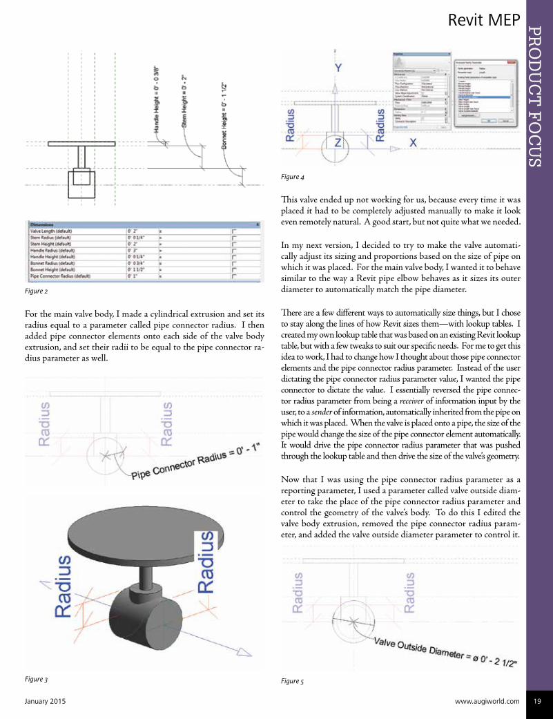
This valve ended up not working for us, because every time it was placed it had to be completely adjusted manually to make it look even remotely natural. A good start, but not quite what we needed.
In my next version, I decided to try to make the valve automati-cally adjust its sizing and proportions based on the size of pipe on which it was placed. For the main valve body, I wanted it to behave similar to the way a Revit pipe elbow behaves as it sizes its outer diameter to automatically match the pipe diameter.
There are a few different ways to automatically size things, but I chose to stay along the lines of how Revit sizes them—with lookup tables. I created my own lookup table that was based on an existing Revit lookup table, but with a few tweaks to suit our specific needs. For me to get this idea to work, I had to change how I thought about those pipe connector elements and the pipe connector radius parameter. Instead of the user dictating the pipe connector radius parameter value, I wanted the pipe connector to dictate the value. I essentially reversed the pipe connec-tor radius parameter from being a receiver of information input by the user, to a sender of information, automatically inherited from the pipe on which it was placed. When the valve is placed onto a pipe, the size of the pipe would change the size of the pipe connector element automatically. It would drive the pipe connector radius parameter that was pushed through the lookup table and then drive the size of the valve’s geometry.
Now that I was using the pipe connector radius parameter as a reporting parameter, I used a parameter called valve outside diam-eter to take the place of the pipe connector radius parameter and control the geometry of the valve’s body. To do this I edited the valve body extrusion, removed the pipe connector radius param-eter, and added the valve outside diameter parameter to control it.
Figure 5
Figure 2
For the main valve body, I made a cylindrical extrusion and set its radius equal to a parameter called pipe connector radius. I then added pipe connector elements onto each side of the valve body extrusion, and set their radii to be equal to the pipe connector ra-dius parameter as well.
Figure 3

PR
OD
UC
T F
OC
US
20 www.augi.com January 2015
Revit MEP
I realized through experimenting with valves and pipe sys-tem types that, as in the field, the pipes were rarely actually the nominal diameter that they claimed to be; i.e., a 2” pipe does not actually have a 2” outside diameter. The actual out-side diameter of a pipe is usually a bit larger than the nominal diameter, and I needed to get the valve body’s outside diameter to match with the pipe’s outside diameter so it would display correctly and size according to the Revit pipe system families. To ease the strain of converting parameters back and forth from radius to diameter, and to act a stepping stone from the pipe connector radius parameter to the lookup table formulas, I cre-ated a parameter called nominal diameter, and set it equal to pipe connector radius * 2.
Figure 6
This is the parameter that I would use in the lookup tables and their formulas. Valve outside diameter was being driven by this lookup table formula, and it ended up being the parameter that I used as a basis to size the valve’s geometry parameters’ formulas. So the information was being passed from the pipe connector ele-ment to pipe connector radius, then converted to nominal diam-eter, then run through the lookup table formula to drive the valve outside diameter parameter.
In Figure 7 you can see the general breakdown of these param-eters. For the formula for valve outside diameter, I mimicked a Revit formula that it uses for pipe elbows, which is pretty stan-dard. For the lookup table, I used my custom table with my additions, and for the other ancillary geometry of the valve, I multiplied nominal diameter times a factor to get them to look appropriately sized and proportioned.
Figure 7
I wish that I could say that I scientifically came up with the fac-tor numbers, but in reality I completely made them up. I refined the numbers to be just right through trial and error by flexing the valve’s size in the family environment from the smallest to the larg-est size, and making sure that the valve always looked proportional and correct.
Now that I had this valve that auto-adjusted when you placed it, I felt pretty good. But I could no longer manually change the valve when I needed to. Ideally, I wanted the valve to auto-size when placed, then if needed the user could manually tweak the size of the valve handle, etc.
Enter the If-Then formula! After thinking about it for a while, I realized that the only way to get the valve to behave in that way was to cleverly use an If-Then formula. To keep my precious exist-ing formulas intact and have them be adjustable, I had to imple-ment placeholder parameters. I created three instance parameters for this: Valve Length User Input, Stem Height User Input, and Handle Radius User Input.
Next, to make the switch between auto-adjust and manual adjust, I created two Yes/No instance parameters: Valve Length Is Ad-justable, and Valve Handle Is Adjustable.
Figure 8
The If-Then formulas basically say: If the Adjustable checkbox is checked, then use the user inputted value; if not, then use the original auto-sized value. This combination worked beauti-fully. The user could place the valve, have it auto-size to get it close, then the user could check the Adjustable checkbox and tweak the size as needed.
To further aid in the ease of manual adjustment, I added some reference planes and dimensions, setting the dimensions equal to the three user input parameters. This made grips show up when in a project, so the user could graphically drag the grip to size the user input parameters instead of repeatedly inputting numerical values to try to match the point cloud.
Figure 9

Revit MEP PR
OD
UC
T F
OC
US
January 2015 www.augiworld.com 21
Figure 10
For additional flexibility of the valve family, I wanted to make it ro-tate along the pipe. As it sat, the user could rotate it in 90-degree in-crements by clicking the small rotate icon when the valve is selected, but I wanted more. I wanted it to be rotated in any direction, at any angle. To achieve this, I nested this family into a second family.
I learned the hard way that you must have the original family mod-eled as a face-based family for this to work. After remodeling the en-tire original family, I had a family that was prepared to be nested into the final fully rotatable family. I first set up a jig that would rotate my nested family. I created a reference line and locked the endpoint to both axes of the origin. Then I put an angular dimension from the X axis to the reference line and assigned it to a parameter valve rotation. Next, I loaded the nested family into the host family and I hosted it to my reference line rotation jig.
Figure 11

Revit MEPP
RO
DU
CT
FO
CU
S
22 www.augi.com January 2015
Figure 12
To get the valve’s geometry to size, I simply created the necessary parameters and linked them with the nested family’s parameters. I also added pipe connector elements and set their radii equal to the newly created pipe connector radius parameter.
Figure 13
Figure 14
Again, to ease in the manual adjustment of the valve handle, stem height, and so on, I created some reference planes to make the grips appear when in a project environment.
Kyle Schicker is an electrical BIM/CAD technician with The Schemmer Associates. He has more than 15 years of experience with AutoCAD and more than 5 years of experience with Revit. With work experience in architectural, structural, mechanical, and electrical disciplines, Kyle has a unique versatility with multidisciplinary practices. Serving on Schemmer’s CAD Committee, he helps improve the BIM and CAD workflow by creatively collaborating with the BIM Manager and other disciplines. He loves pushing the limits of Revit, and building advanced and complex families. In his spare time Kyle enjoys mountain biking, playing guitar, and tinkering with 3DS Max to create realistic renderings.
Figure 15
With this combination, I had finally reached my goal. I had a fam-ily that had the best of both worlds: It would auto-size when users needed it to, and also be adjustable if users needed that. I was able to meet the niche needs of our company and make life easier and more efficient for the users.
Figure 16


PR
OD
UC
T F
OC
US AutoCAD Architecture 2015
PR
OD
UC
T F
OC
US
24 www.augi.com January 2015
by: Melinda Heavrin
It is important to note that the DST file should be stored in a network location that is accessible to all sheet set users on the net-work and mapped using the same logical drive. It is strongly rec-ommended that you store the DST and the sheet drawings in the same folder. If an entire sheet set needs to be moved, or a server or folder name changes, the DST file will still be able to locate the sheets using relative path information.
OVERVIEW
Before you begin creating a sheet set, several steps should be com-pleted. First, drawing files need to be consolidated. Move the drawing files to be used in the sheet set into a small number of fold-ers in order to simplify sheet set administration. Second, eliminate multiple layout tabs. Each drawing you plan to use in the sheet set should have only one layout to be used as a sheet in the sheet set. This is important for access to sheets by multiple users, as only one sheet in each drawing can be open at a time. Third, create a sheet creation template. To do this, create a drawing template (DWT) file to be used by the sheet set for creating new sheets. You specify this template file in the Sheet Set Properties dialog box or the Sub-set Properties dialog box. Fourth, create a page setup overrides file. Create a DWT file to store page setups for plotting and publish-
Sheet sets are an excellent tool in AutoCAD® Architecture. A sheet set is an organized col-lection of sheets from several drawing files. A sheet is basically a selected layout from a
drawing file. Sets of drawings are the primary de-liverable for most design groups. Sets of drawings communicate the overall design intent of a project and provide the documenta-tion and specifications for the project. However, managing sets of drawings manually can be complicated and time consuming. With the Sheet Set Manager, you can manage drawings as sheet sets. A sheet set is an organized and named collection of sheets from several drawing files. A sheet is a selected layout from a drawing file. You can import a layout from any drawing into a sheet set as a numbered sheet.
A sheet set can be created with the Create a Sheet Set wizard. In the wizard, you can either create a sheet set from scratch based on existing drawings or use an example sheet set as a template. Layouts from specified drawing files are imported into the sheet set. The associations and information that define a sheet set are stored in a sheet set data (DST) file. When you create a new sheet set using the Create Sheet Set wizard, a new folder is created as the default sheet set storage location. This new folder, which is named AutoCAD Sheet Sets, is located in the My Documents folder.
Speed and Simplify with
Sheet Set Manager

AutoCAD Architecture 2015 PR
OD
UC
T F
OC
US
January 2015 www.augiworld.com 25
ing. This file can be used to apply a single-page setup to all sheets in a sheet set, overriding the individual page setups stored in each drawing. It is important to note here that although it is possible to use several layouts from the same drawing file as separate sheets in a sheet set, it is not recommended because it makes concurrent access to each layout by multiple users impossible. This practice can also reduce your management options and can complicate the organization of your sheet sets.
In the Create Sheet Set wizard, when you choose to create a sheet set from an example (see Figure 1), the example sheet set provides the organizational structure and default settings for the new sheet set. You can also specify that folders are created cor-responding to the subset storage paths of the sheet set. After you create an empty sheet set with this option, you can import layouts or create sheets individually.
In the Create Sheet Set wizard, when you choose to create a sheet set from existing drawing files (see Figure 1), you specify one or more folders that contain drawing files. With this option, you can specify that the subset organization for the sheet set duplicates the folder structure of the drawing files. The layouts from these draw-ings can be imported into the sheet set automatically. You can eas-ily add more folders containing drawings by clicking the Browse button for each additional folder.
Figure 1: Create a new sheet set
IMPORT A LAYOUT INTO A SHEET SET
After you create a sheet set, you can import one or more layouts from existing drawings. You can initialize a layout by clicking on its tab to activate the previously unused layout. A layout does not contain any plot settings before initialization. Once initialized, layouts can be drawn upon, published, and added to sheet sets as sheets after the drawing has been saved. This is a fast method for creating multiple sheets from layouts in several drawings. In the current drawing, you can drag a layout tab directly onto the Sheets area of the Sheet List tab in the Sheet Set Manager.
To import a layout into a sheet set, begin by clicking the View tab on the Palettes panel and select Sheet Set Manager. In the Sheet Set Manager, Sheet List tab, right-click the sheet set node, a subset node, or a sheet node and then click Import Layout as Sheet (see Figure 2). In the Import Layouts as Sheets dialog box, click Browse for Drawings and then navigate to the drawing you want to use. If you wish to select several drawings, use SHIFT or CTRL when you click on the drawing files. Next, click the check boxes of the layouts to be imported as sheets in the current sheet set and click Import Checked.
Figure 2: Import a layout into a sheet set
CREATE A NEW SHEET IN A SHEET SET
As an alternative to importing existing layouts, you can create a new sheet. When you place views in this sheet, the drawing files associated with the views are attached as xrefs to the sheet draw-ing. To create a new sheet in a sheet set, begin by clicking the View tab on the Palettes panel and select Sheet Set Manager. In the Sheet Set Manager, Sheet List tab, right-click on the sheet set node and then click New Sheet. You can now select a drawing template and layout and then select OK.

AutoCAD Architecture 2015P
RO
DU
CT
FO
CU
S
26 www.augi.com January 2015
RE-ASSOCIATE A SHEET IN A SHEET SET
If you move a sheet to a different folder, you should re-associate the sheet to the sheet set with the Sheet Properties dialog box to correct the path. For any relocated sheet drawing, the paths for Expected Layout and Found Layout are displayed in the Sheet Properties dialog box. To re-associate the sheet, click the path in Expected Layout and then click to navigate to the new location of the sheet. It is important to note that you can quickly confirm whether a sheet is in the expected folder by looking at Details at the bottom of the Sheet List tab. If the selected sheet is not in the expected location, path information for both Expected Location and Found Location is displayed in Details.
To re-associate a sheet in a sheet set, begin by clicking the View tab on the Palettes panel and select the Sheet Set Manager. In the Sheet Set Manager, open a sheet set. Now on the Sheet List tab, open the sheet that you want to re-associate. Next, in the Sheet Set Manager, right-click the sheet you wish to remove and then click Remove Sheet. Save the drawing. In the Sheet Set Manager, right-click the Sheet Set and click Import Layout as Sheet. In the Import Layout as Sheet dialog box, click Browse for Drawings and navigate to the drawing you wish to use. Click the check box of the layout to be re-associated as a sheet in the current sheet set and click Import Checked (see Figure 4).
Figure 4 – Re-associate a sheet in a sheet set
CREATE A NEW SUBSET
Sheet subsets are often associated with a discipline such as ar-chitectural, electrical, and so on. For example, in architecture you might use a subset named structural, and in electrical you might use a subset called lighting. In some cases, you might also find it useful to create subsets associated with a review or completion status. Subsets can be nested into other subsets as needed. After you create or import sheets or subsets, you can reorder them by dragging them in the tree view.
To create a new subset, begin by clicking the View tab on the Pal-ettes panel and select Sheet Set Manager. In the Sheet Set Man-ager, Sheet List tab, right-click the sheet set node or an existing subset and click New Subset. In the Subset Properties dialog box, under Subset Name, enter the name of the new subset, and click OK (see Figure 3). You can drag the new subset anywhere on the sheet list, even under other subsets. It is important to note that if you want to create a subset under an existing subset, you can right-click the existing subset. On the shortcut menu, click New Subset.
Figure 3: Create a new subset

AutoCAD Architecture 2015 PR
OD
UC
T F
OC
US
January 2015 www.augiworld.com 27
ADD A VIEW TO A SHEET
From the Model Views tab, you can easily add a view to a sheet by placing a named model space view or the entire drawing onto the current sheet. It is important to note that after creating a named model space view, you must save the drawing to add the view to the Model Views tab. Click Refresh on the Model Views tab to update the Sheet Set Manager tree view.
To add a view to a sheet, begin by clicking the View tab on the Palettes panel and select Sheet Set Manager. In the Sheet Set Manager, open a sheet set. On the Sheet List tab, you can either double-click on a sheet to open it, or create a new sheet and open it. On the Model Views tab, click the plus sign next to a folder to list the drawings in the folder.
From the list of drawing files, do one of the following:
• To add a model space view to a sheet, click the plus sign next to a drawing file to list its named model space views and then right-click a model space view.
• To add an entire drawing as a view in a sheet, right-click a draw-ing file.
Click Place on Sheet. As an alternative, you can also drag a model space view or a drawing from the Model Views tab to a sheet.
Now right-click on the sheet and then click the scale you wish to use for the sheet view. Specify the insertion point for the sheet view. The specified view is now added to the sheet. If a view label block is defined in the sheet set properties, a view label that displays view-specific information is automatically placed on the sheet.
ADD A SHEET LIST TABLE
The first sheet in a sheet set will usually be a title sheet that in-cludes a description of the sheet set and a table that lists all the sheets in the sheet set. You can create this table, called a sheet list table, on an open sheet. The table automatically includes all the sheets in the sheet set. Once a sheet list table is created, you also have options to edit, update, or delete the cell content of the table.
To add a sheet list table, begin by clicking the View tab of the Palettes panel and select Sheet Set Manager. In the Sheet Set Manager, open a sheet set. Right-click a sheet set name, sub-set, or multiple sheet set names and subsets and then click Insert Sheet List Table. In the Insert Sheet List Table dialog box, set the Table Style in the Table Style Settings group. Next, on the Table Data tab, specify Title Text for the table and add, remove, or change the order of the column entries. On the Subsets and Sheets tab, select the subsets and sheets to be included in the sheet list table. Please note that if you add a sheet to a subset later on, you will be automatically prompted to update the sheet list table. Click OK.
Melinda Heavrin is a CAD Coordinator & Facility Planner for Norton Healthcare in Louisville, Kentucky. She has been using AutoCAD Architecture since release 2000. Melinda can be reached for comments and questions at [email protected]
PUBLISH A SHEET SET
From the Sheet Set Manager, you can easily publish an entire sheet set, a subset of a sheet set, or a single sheet. It is quicker to publish a sheet set in the Sheet Set Manager than to use the Publish dialog box. When you publish from the Sheet Set Manager, you can publish an electronic sheet set by publish-ing to a DWF, DWFx, or PDF file, or you can publish a paper set by publishing to the plotter named in the page setup that is associated with each drawing sheet. You can also publish your sheets using a page setup that is saved in the page setup overrides DWT file associated with the sheet set. This page setup overrides the current page setup settings for the indi-vidual publish job.
When you open the Publish dialog box from the Sheet Set Manager, the dialog box automatically lists the sheets you se-lected in the sheet set. You can then modify the sheet set for publishing. It is important to note that you can specify that sheets are sent to the plotter in reverse order. This option is available from the Publish dialog box and from the Sheet Set Manager.
Figure 5: Publish a sheet set

AutoCAD Civil 3D 2015P
RO
DU
CT
FO
CU
S
28 www.augi.com January 2015
by: Shawn Herring
Out of all groups, companies, and indi-viduals for which I have provided Au-toCAD® Civil 3D® implementation and training, the surveyors seem to be the
ones who just pick Civil 3D apart. And I LOVE it! I enjoy the challenges and enjoy when people try to “break” the software. There are still several things I would like to see changed and added to the survey portion of Civil 3D, but we will work on that another day.
For now, I chose to look at a few features that are often overlooked or just hard to find. The re-creation of a simple legal description or just double checking for error of closure can be a much simpler task than some make it out to be. I have seen several third-party apps that work well, but I like to work with what I already have and already paid for.
Hidden Survey Gems

AutoCAD Civil 3D 2015 PR
OD
UC
T F
OC
US
January 2015 www.augiworld.com 29
Figure 1: Re-create this!
Within the article you will find specifics on the following.
• How to input data in the Coordinate Geometry Editor and run results and reports from one simple interface. Some deeds re-quire a lot more input than the typical tools will allow, so one of the only ways to re-create some deeds may be done by using this COGO Editor.
• We will also explore some other useful COGO tools. The Map-check Analysis tools are a great way of checking things as well.
• There are also numerous other features in AutoCAD Civil 3D 2015 and past releases that may be very useful in a survey workflow.
For the files used in this write-up, you can contact me directly and I will email them over. My email can be found within the bio at the end of this article. Or just use a file of your own and give it a shot!
Also, this is a bit of a revamp on a past Autodesk University session I presented. If you want more detail, search the AU classes for:
CI2837: Hidden Survey Gems
PERFORMING A MAPCHECK ANALYSIS IN CIVIL 3D
You can perform a Mapcheck Analysis by selecting AutoCAD Civil 3D line and curve labels to determine values from label ob-jects based on the precision of the annotation of the label object, or you can enter mapcheck data manually.
A mapcheck analysis is typically performed for each labeled polygon that represents a parcel, a labeled parcel object, or survey figure to ensure that errors and omissions are minimized. If an error is introduced and ac-cumulated, the coordinates of the last segment endpoint will not equal that of the point of beginning (POB) which creates the “error of closure.”
The report is computed based on the start and end coordinates of each parcel segment, relative to the coordinates of the POB and the previous segment.
Figure 2: Mapcheck Analysis command
You can change the Mapcheck default command settings in the General collection on the Settings tab in Toolspace.
To Change Mapcheck Command Settings:
1. On the Settings tab in Toolspace, click General > Com-mands > MapCheck.
2. In the Edit Command Settings-MapCheck dialog box, ex-pand the Mapcheck group and specify values for the Map-check properties.

AutoCAD Civil 3D 2015P
RO
DU
CT
FO
CU
S
30 www.augi.com January 2015
Figure 3: Mapcheck settings
1. Open the 1_Perform Mapcheck Analysis.dwg.
2. Click Analyze tab > Ground Data panel > Survey drop-down > Mapcheck .
3. In the Mapcheck Analysis window, click New Mapcheck Report.
4. In the command line, enter a name for the Mapcheck, call the first one BOUNDARY. We will be doing the outer boundary that consists of four calls.
5. In your command line, specify a Point of Beginning. Choose the UPPER LEFT corner of the property line. The interactive graphics display the POB in the drawing.
6. At the command line you are prompted to select a label. After selecting a label, the interactive graphics display in the draw-ing. If you need to make a change, at the command line you have options to do the following:
a. Clear: Clears the current side
b. New: Starts a new Mapcheck report
c. Flip: Changes the direction of the curve to either clockwise or counter-clockwise
d. Reverse: Changes the direction of the line or curve
7. Select the labels in Clockwise order. Hit Enter to end the command after the four labels have been chosen.
8. Your Mapcheck Analysis should look similar to Figure 4.
INSERT A MAPCHECK ANALYSIS AS MTEXT OR POLYLINE
You can export the Mapcheck results in a couple different ways. From left to right along the dialog box you can perform the following.
Copy to Clipboard
Copies the contents of the input view or output view to the Win-dows clipboard.
If a mapcheck is current, then only that mapcheck is copied to the clipboard. If no mapcheck is current, then all mapchecks are cop-ied. Press ESC to clear a selection in tree view.
Insert MTEXT
Inserts the contents of the input view or output view as an Mtext object in the drawing.
If a mapcheck is current, then only that mapcheck is inserted into the drawing. If no mapcheck is current, then all mapchecks are in-serted into the drawing as separate Mtext objects. Press ESC to clear a selection in tree view.
Create Polyline
Inserts a polyline into the drawing representing the current mapcheck. If there is no current mapcheck, then a polyline for all mapchecks is inserted into the drawing. Press ESC to clear a selection in tree view.
Figure 5: Insert Mapcheck options
USING THE COGO (COORDINATE GEOMETRY) EDITOR
With the latest Subscription Productivity Pack (2015 Productiv-ity Pack Version 2) for Civil 3D 2015, the COGO Editor tool has
Figure 4: Mapcheck Analysis dialog box

AutoCAD Civil 3D 2015 PR
OD
UC
T F
OC
US
January 2015 www.augiworld.com 31
undergone a great makeover from past versions. The command is now launched, for the time being, from the Toolbox panel of the Toolspace, under the Subscription Extension Manager. The origi-nal method is still available for those that are not on subscription.
The Coordinate Geometry Editor includes features that enable you to enter, edit, and output 2D traverse data.
You can create 2D traverses from existing COGO data, load it from a polyline, or manually enter known data. You can save tra-verses for later modification or generate traverse reports.
Figure 6: COGO Editor interface
Let’s create the following deed, or use one of your own.
From the POINT OF BEGINNING, the following eight calls:
Thence, S 62°13’04” E, 65.21 FEET
Thence, S 38°48’58” W, 91.14 FEET
Thence, S 51°11’02” E, 20.00 FEET
Thence, S 38°48’58” W, 75.00 FEET
Thence, N 51°11’02” W, 20.00 FEET
Thence, S 38°48’58” W, 25.00 FEET
Thence, N 51°11’02” W, 64.00 FEET
Thence, N 38°48’58” E, 178.66 FEET to the POB.
There are some general guidelines for creating/entering data. You can load data into the COGO Editor by selecting an existing poly-line within your drawing or by manually entering known data, which we will use in this example.
Quick Tips
• Use the Tab, Enter, or Arrow keys to navigate between cells
• To use another unit of measure, entire either ‘ or m. For example, if you are working in Imperial units and have an input in meters, simply type in 200m
My favorite feature is the use of mathematical equations to cal-culate traverses. I know it’s hard to believe, but people still have deeds written in CHAINS! So doing the math each time gets a bit annoying.
The following operators are valid inputs:
+ - / * ()
For example, to convert a distance call from 7.5 CHAINS to FEET, simple type in 7.5*66.
To calculate the angle, direction or distance between points 1 and 2, and then divide by 2, type in (1 to 2)/2.
To return the sum of multiple values at the same direction, just type in a simple addition equation. Input 100+225.34+372.19 to get the overall distance of a contiguous line.
CREATING YOUR FIRST DEED WITH THE COGO EDITOR
You can enter traverse data in the COGO Editor by creating tra-verse sides. Side types can be Point, Line, Arc, or Side Shot. The first side type of the traverse must be a point.
1. In the Toolspace on the Toolbox tab, expand Subscription Ex-tension Manager > Civil 3D Productivity Pack > Coordinate Geometry Editor. Double-click Launch Coordinate Geome-try Editor to display the COGO Editor.
2. Ensure that the Entry tab is active and click to create a new traverse.
3. Ensure that Point is specified as the first Side type.
4. Enter parameters in the first row of the COGO Editor for the point. Either enter an XYZ or select a COGO point within the drawing. For this example, choose any point on screen.
5. Specify subsequent Side types, and then specify the requisite parameters. Input the following:
a. s 62 13 04 e (For Angle), 65.21 (For Distance)
b. s 38 48 58 w, 91.14
c. You can also type the angle as 62.1304
6. You will see temporary graphics being placed, and labeled, on your screen!
Figure 7: COGO Editor – temporary graphics

AutoCAD Civil 3D 2015P
RO
DU
CT
FO
CU
S
32 www.augi.com January 2015
Shawn Herring is a civil engineer based out of Utah. Shawn has been a part of the design engineering community for roughly 12 years in all aspects of design, construction and software implementations. He has implemented and trained companies across the Country on Civil 3D and other infrastructure tools and their best practice workflows. Shawn can be reached for comments or questions at [email protected] .
7. Continue on with the DEED as described in full above.
TIP: You can right-click in the COGO Editor to access a context menu with commands you can use to delete a row, to insert a row between existing rows, and to reorder rows.
8. Click the CREATE POLYLINE FROM TRAVERSE but-ton along the top of the dialog box.
9. The POLYLINE ADDED TO DRAWING box will appear; select OK. The polyline is now drawn in your model space.
There are many other benefits to using this COGO Editor—too many to list here, but it is such a simple interface that you can play with it for a few minutes and quickly get things figured out.
There is also a Balance tab on the dialog box. Use this tab to specify an adjustment method to use and to review the adjusted data.
ADDITIONAL GEMS IN SURVEY DATABASES
Save Survey Database
Save Survey Database to 2014 Utility for AutoCAD Civil 3D 2015. This will downgrade you survey database(s) in order to be used with 2014 Civil 3D. Civil 3D 2015 uses a SQL Server Compact 4.0 format, Civil 3D 2014 uses a SQL Server Compact 3.5 format for the survey database file. If the 2015 file is downgraded back to a 3.5 file format, then it will be usable with Civil 3D 2011 through Civil 3D 2014.
Survey Database Queries
Did you know you can query a survey database for survey points and figures that meet specified criteria?
A survey query enables you to search a survey database for the survey points and figures that meet a specified series of conditions. A sur-vey query is associated with and saved in a survey database. A survey query can query only the points and figures within its host database.
Figure 8: Survey database query
After a survey query has been executed, you can display the result-ing survey points and figures in the drawing as a preview. You can make changes to the survey points and figures, and then save the changes back to the survey database.
A surface can be built from the results of a survey query. The results can be added to a surface definition either as static point groups and breaklines, or as a dynamic reference to the survey points and figures that are in the survey database.
Label a Line Between Two Points
I know this is a simple one, but this is something that was miss-ing up until the 2013 release. You now have the functionality to quickly label line information between any two COGO or survey database points. You can also just select two points on the screen or along a line. Great for spanning distances.
1. Draw a line or just open any file and go to the Annotate Tab of the ribbon.
2. Annotate > Line and Curve > Add Line Between Two Points label.
3. Select any two points using the node OSNAP or a transpar-ent command of your choice.
CONCLUSION
Hopefully you will find some of these tools useful. Try it out on a couple simple projects and I think you’ll get hooked! I espe-cially like the COGO Editor for verification and closure reports, and once you get accustomed to using the Survey Databases, those queries that you can run will be extremely valuable within your survey workflows.

BIM Construction PR
OD
UC
T F
OC
US
January 2015 www.augiworld.com 33
by: Tom Fuller
In an effort to provide a higher quality BIM at the design level, PCI Skanska, the engineering division of Skanska USA Civil Midwest, adopted Sys-
Que for Autodesk® Revit® for mechani-cal and plumbing design modeling. All Revit projects produced in our office are built on real-world content. However, given that engineering firms typically do not specify exact manufacturers for their pipe construction specifications, but instead provide the requirements to which the pipe systems must adhere (e.g., ASTM stan-dards, schedule, material, and so on), we discussed with Industrial Contractors Skanska (the construction por-tion of Skanska USA Civil Midwest with which we typically have design-build projects) their preferred pipe construction specifications.
Essentially, we as engineers need to design and coordi-nate mechanical systems in a building where the pipe specification may have real-world implications on in-stallation. Drawing with unrealistic content, or com-pletely different content than what is likely installed, is a hazard to the project. If we know we want a water system installed with a grooved pipe specification, why not match what our sister company will likely install? Why design and coordinate with fittings that simply do not exist in the real world? SysQue and Building Data provide us this solution in the Revit environment where my team happily and efficiently coexists with our other in-house architectural, structural, and electrical design teams.
To begin, I looked at the text version of the various pipe construction specifications we typically used for our de-sign projects and made changes where the engineering specifications did not entirely match the construction preferences. I regrouped the pipe specifications by the
Design-Level
BIM
Figure 1

BIM ConstructionP
RO
DU
CT
FO
CU
S
34 www.augi.com January 2015
pipe construction specification itself rather than the fluid system type (i.e., butt-welded rather than chilled water supply). Because Revit allows us to have separate system definitions by fluid type and design purpose, our Revit pipe types can be based on the ac-tual pipe construction specification rather than the fluid within the pipe. One Revit pipe type is available for multiple system types, rather than having a different pipe type for every system type. This reorganization also assists designers and engineers with choosing appropriate pipe construction specifications by seeing where each specification is applicable. Once I created the matrix of pipe con-struction types with available fluid design purpose (see Figure 1), I organized the written specifications by this new index (Figure
2). The written specifications typi-cally found in spec books or on the first few sheets of drawing packages are now indexed in a Microsoft Word file in the same order as the matrix.
Next I had to choose real-world con-tent for our Revit projects. To popu-late our SysQue “Systems.xml” file, I created a tabbed Microsoft Excel file (Figure 3) detailing each pipe construction specification’s key com-ponents such as pipe type, fittings, valves, flanges, unions, and so on. I chose a specific manufacturer and model number for every component listed in our text-based specs in con-sultation with our construction esti-mators. Armed with the Excel file, I looked at the default SysQue “Sys-
tems.xml” file and using Microsoft Visual Studio Express 2013 for Windows, I began cutting, pasting, renaming, and rearranging the default build to suit my new organized and indexed pipe con-struction specifications (Figure 4). Where the default arrangement of components did not match my needs, I used SysQue’s built-in method of adding content to my “System.xml” file (see Figure 5). Where content was not available as part of the initial install, I used www.Building-Data.net to download the remaining Revit families (Figure 6). If I came across a key component for our pipe specifica-tions that was not available, I requested that the Revit content be created by Building Data by submitting a manufacturer’s submittal sheet through the website.
Figure 3
Figure 4
Figure 2

BIM Construction PR
OD
UC
T F
OC
US
January 2015 www.augiworld.com 35
Tom Fuller is a mechanical designer with PCI Skanska, part of Skanska USA Civil Midwest. Tom has brought his skills acquired from ten years as part of SMWIA Local 20 to the engineering side of the construction industry. His first job involving BIM was a hospital tower expansion using CADmep and CAMduct in 2009 and has experience in complete shop database setup. Tom now uses his trade skills to create more accurate construction documents and building models at the engineering/design level. Initially utilizing CADmep on the engineering side, Tom has since switched to Revit with SysQue content to facilitate a more cohesive design environment without sacrificing the need for constructible models.
Figure 5
Figure 6
Figure 7
What began as an engineering firm choosing pipe specifications based on someone’s idea of what it should/could be and a con-struction firm installing pipe types that are a better value to the client, ended as a design-to-construction process. The process was built on installed components matching designed components where the designed components were modeled by knowing what the preferred installed components would be. Our Revit pipe types have an indexed system family name that coincides with our pipe specification text (see Figures 7 and 8).
Figure 8

Inventor 2015P
RO
DU
CT
FO
CU
S
36 www.augi.com January 2015
by: John Evans
We at Design & Motion purchased a seat of Fusion 360 Ultimate, which might bring to mind the question, “Why?”
Well, one is price. $300 per year for a good modeler, static simu-lation, and 5-axis CAM is a bloody steal. Another reason is we are usually in the front line of making things work for engineering workflows, and we see some hope in the future of Fusion 360. It’s better to be on top of something than to be run over by it.
However, there is one thing that Fusion 360 Ultimate will not change for at least three years: My love of Autodesk Inventor® Professional. Hands down, for day-to-day, blood, sweat, and tears work, Inventor is my choice. Fusion is gaining ground quickly, but it isn’t there yet. There are [at least] 10 reasons why I would never let go of Autodesk Inventor. Perhaps the Fusion 360 team will take a hint or two.
#10 – PARAMETRIC TOLERANCING
I love tolerance parameters, and I appreciate the time Autodesk spent on including standards such as shaft and hole fits. Once es-tablished, parameters within the design can be shifted from Maxi-mum Material Condition (MMC) to Least Material Condition (LMC) with the push of a button. Features update accordingly and can be inspected visually or by measurement.
#9 – DESIGN ACCELERATORS
If you use any of the Design Accelerators you probably know where I am coming from. For all their quirkiness, we still use Design Ac-celerators because they are mostly brilliant. The Bolted Connec-tion Generator, Belt generators, fastener load calculations, Bearing Generators, Spline Generators, and, dear Lord, don’t forget the Frame Generator with standard wall thickness frame components. There is just no end to the things I use in this list.
#8 – THE ENVIRONMENTS
Fusion 360 will include a linear static stress analysis environment. If it ends up being the build from SIM 360, then it will be a very valuable tool indeed.
However, Inventor still holds a list of comprehensive arenas in which to compose, conform, and study components for various uses and needs, including the wonderful Dynamic Simulation environment.
10 Reasons Why Inventor Is Still My Sweetheart

Inventor 2015 PR
OD
UC
T F
OC
US
January 2015 www.augiworld.com 37
#7 – CONSTRAINTS STILL WORK BETTER
It still irritates me that joints in all software titles (including Inven-tor) cannot simply place and maintain a rounded face tangent to a flat plane. We have been able to do that with Inventor Constraints since what... Version 5? There is virtually no combination that can-not be assembled using Inventor’s Constraints. I don’t mind apply-ing two in order to achieve an assembly goal.
Joints are included in Inventor and Fusion 360, and while handy (and in most cases pretty nifty), are difficult to manage if your de-sign does not fit a “typical” use situation.
#6 – VAULT
Vault Basic comes free with Autodesk Inventor. I have never been sure whether that is to entice people to buy the powerful Vault alternatives, such as the Professional version, or is just Autodesk’s kindness. Either way, that option is not available for Fusion 360. While management in PLM 360 seems to be on the horizon in some manner or another, it will likely be some time before its capa-bilities are as easy and useful as even the lowliest of the Vault titles.
#5 – FASTENERS
You have no idea. Really!!
If you have been using Inventor for any length of time, then close your eyes and imagine that you have no fasteners. In fact, you get to build your entire library—right down to the last snap ring—from scratch. Frightening [shudder].
Inventor’s Content Center is slam-filled with most things that we require on a daily basis. I do note that there is a shocking lack of Torx screws, nuts, and bolts. Inventor does, however, allow users to customize the library and add this family of fasteners (as well as any others) when needed.
#4 – HOLES
Inventor delivers a comprehensive list of hole and thread specifica-tions. Have you tried adding fastener holes without the integrated specifications lately? That productivity alone has become quite valuable to me recently as I do not remember every counterbore depth and diameter.
#3 – DRAWINGS
Fusion 360 Ultimate’s drawing capabilities are delivered in the form of a very basic technology preview for the purposes of gath-

Inventor 2015P
RO
DU
CT
FO
CU
S
38 www.augi.com January 2015
ering feedback for future releases. I am sure these will have more capabilities as time moves forward.
That said, it will be a long while before Inventor’s drawing capabilities and engineering automation are replaced by another Autodesk product.
#2 – TOP DOWN MODELING
Inventor has been developed over the years to not only store and calculate mathematic variables, but also to import these from Excel spreadsheets (a very powerful option in some circumstances). These can be expressed in the model in numerous ways including sketches, model and work features, and sketch blocks to name a few.
These can then be leveraged within downstream parts such that as the overall controlling variables change, so the parts adapt… auto-matically. Inventor is built to do this well.
This aspect is one that we are currently investigating within Fusion 360. While this has potential in the future, Inventor has been tai-lored to accomplish this goal with ease.
#1 – EASE OF USE
I think the biggest area where Autodesk has polished Inventor is automation and ease of use. You get what you pay for, and in this sense Inventor delivers. Here are some examples.
Creating Work Planes can be achieved by explicit and interpreted meth-ods. You can specify the explicit combination of objects to define a Work Feature; however, Inventor will, by default, take any combination of ob-jects and try to interpret how to support your Work Feature. In most cases the result is straightforward from a single pick on the ribbon.
Associative Patterning, another area of refinement, is the ability to create a pattern of bolts for example, using the existing pattern of fastener holes these will be applied to. This is a brilliant way of reusing information within Inventor.
Fusion 360 has possibly more modeling features than does Autodesk Inventor. However, Fusion falls terribly short in terms of automation, often requiring explicit selection from a long pull-down to accomplish a goal. Autodesk Inventor, on the other hand, often only requires a general nudge in a direction and it sorts the rest of the details automatically.
CLOSING THOUGHTS
It was hard to put these into any order of importance and they are only the tip of the iceberg. Fusion 360 in all its fanfare is still a new platform with a lot of room for growth, but also a lot of room for polish. If you had the opportunity to jump in on the Fusion 360 Ultimate promotion for $300 USD per year, you did well. We ex-pect it to continue to be developed and hopefully meet the greater need of designers and engineers.
However, if you did not get in on Autodesk’s version of a Black Fri-day sale, then you have to ask yourself if the initial purchase cost of Inventor, plus the subscription maintenance, is worth the features that you would be missing, per seat.
In Fusion 360’s current state, it is well suited to job shops and com-panies that do not rely on technical standards for machinery and transportation in their respective industries. For these businesses, the cost benefit and ability to read in almost any model and clarify it to a particular manufacturing process is a win-win.
For companies that rely on libraries of fasteners, continuous review of engineered joints, and complex assemblies that require control and precision, then Inventor is a definite winner.
We will continue to evaluate Fusion 360 Ultimate as it develops to have a clear understanding of what it can and cannot do. However, until such a time it can knock these 10 items off my list, Inventor will remain Design & Motion’s pick from Autodesk’s engineering software line-up.
John Evans is an Autodesk Certified Inventor Professional living in the Florida Panhandle, where he provides technical troubleshooting at Gustin, Cothern, and Tucker, Inc. His career through the Aerospace Design, manu-facturing, and maintenance spans 24 years and includes a tour in the USAF. John now works as a design consultant and author from his com-pany John Evans Design and manages the blog “Design and Motion,” where he combines his passions: Autodesk Inventor, simulation, and motion control. He is a regular attendee of Autodesk University and has recently joined Tekni Consulting as a contrib-uting author for the Creative Inventor training series.He can be reached at [email protected] .
Inside Track CO
LU
MN
Inside Track CO
LU
MN
by: Brian Andresen
January 2015 www.augiworld.com 39
http://bimobject.com/
BIMobject® is a game changer for the construction industry. Man-ufacturers use BIMobject to promote and deliver their products directly into BIM processes, enabling their products to be selected and generate a real improvement in sales.
There are four BIMobject Apps available for SketchUp, Revit, ArchiCAD and AutoCAD that are completely free to download and use. All you have to do is register at bimobject.com.
Revit App: The BIM object App for Autodesk® Revit® inte-grates the BIMobject Cloud into Revit and is one of last year’s most popular downloads among Revit Apps. It’s similar to the BIMobject App for SketchUp and especially suited for building design and construction professionals—for instance, those working in mechanical, electrical, and plumbing (MEP) systems.
AutoCAD App: With the BIMobject App for AutoCAD®, find-ing, downloading, and placing 2D, 3D, and DWG objects into your current project is only a few clicks away.
SketchUp: The BIMobject App for SketchUp is compatible with SketchUp 7, 8, and 2013 for Windows and Mac OS X. Versatile and user-friendly, this app is the perfect sketch tool for just about anyone—architecture students, architects, or interior designers to name a few.
ArchiCAD: The BIMobject App for ArchiCAD is suited for both Mac and PC. It’s the perfect tool for architects and everyone else looking for an app with more advanced features.
https://itunes.apple.com/us/app/constructware-field/id477108945?mt=8
The Constructware® Field mobile app from Autodesk® gives Con-structware users the ability to securely view, download, and upload Architecture, Engineering, and Construction (AEC) project docu-ments and designs from anywhere: field, site hut, or office. Con-structware users can access File Director content to view DWF® files, standard office documents, and images, and even specify files to be available locally when off-network. Additionally, in devices with built-in cameras, Constructware users can take site photos and upload directly to the Constructware cloud for later review and linking to project workflows.
http://bim9.com/
A BIM9 Private BIM Cloud is a solution that utilizes mainstream computer hardware technologies along with custom configura-tions to allow design teams to work on large building information models simultaneously from different physical locations. Located in your office, a BIM9 Private BIM Cloud provides secure access to all of your software applications and design data. Mobile users from around the world can access this data at any time from virtu-
ally any device, including an iPad. A BIM9 Private BIM Cloud gives you all the benefits of cloud computing while keeping
your data fully under your control.
A BIM9 Private BIM Cloud allows you to:
• Connect multiple offices
• Provide remote access to project data
• Maximize your hardware investment
• Achieve true integrated design
If you have some news to share with us for future issues, please let us know. Likewise, if you are a user of a featured product or news item and would like to write a review, we want to know. Contact: [email protected] .
AUGIWorld brings you recent developments in Autodesk and related software items
Welcome to AUGI Inside Track! Check out the latest opportunities to ad-vance your skills, processes, and workflows in your firm, with the most cur-rent AEC-related software and hardware updates available.

Revit StructureP
RO
DU
CT
FO
CU
S P
RO
DU
CT
FO
CU
S
40 www.augi.com January 2015
by: Michael Hopple
According to the fifth annual “SE BIM Survey,” conducted by the BIM commit-tee of the Structural Engineering Insti-tute (SEI) and the Council of American
Structural Engineers (CASE) with the Structural Engineers Association of Texas (SEAoT), 67 percent of respon-dents reported using BIM in their projects (Post, Nadine. “BIM Survey Says More Structural Engineers Use Building Information Modeling.” Engineering News-Record 12 May 2014. Print). Who are the remaining 33 percent and what are their predominate reasons to resist BIM adoption? Is it possible to convince these BIM holdouts to make the transition and catch up with the recent technological advancements of the AEC industry? This article will attempt to diagnose the concerns of non-Revit users and provide real-world experience and advice to ease those concerns.
REVIT ADOPTION CHALLENGES
There is no doubt about it, Autodesk® Revit® adoption is a daunt-ing task for architectural and engineering companies of all disci-plines and sizes. Revit represents a completely new approach to creating construction documents. It is understandable that there are uncertain feelings toward learning an entire new design pro-cess and software package. As BIM manager responsible for Revit implementation across structural, mechanical, and electrical de-partments, I am very familiar with the skepticism and reservations associated with switching from 2D CADD programs to BIM soft-ware such as Revit.
Real Life Perspective:
Transitioning from AutoCAD
to Revit

Revit Structure PR
OD
UC
T F
OC
US
January 2015 www.augiworld.com 41
If your company is still using AutoCAD®, the following comments probably sound familiar:
• There is not enough time to properly train employees.
• Who within the company will lead the implementation process?
• Completing a project in Revit is more time consuming than AutoCAD.
• We will have to create new drafting standards and content libraries.
• Computer upgrades will cost too much.
• AutoCAD drawings just look better than Revit drawings.
• Revit is just a fad and it is not practical for our business.
• We have been successful creating draw-ings the same way for many years. Why change now?
These thoughts are certainly valid, but numerous other questions must be asked and answered before deciding to switch from AutoCAD to a 3D BIM platform such as Revit.
The above comments boil down to a few key points. First, Revit implementation is too time consuming due to employee train-ing. Second, Revit implementation is too costly due to hardware upgrades and new software packages. Last, and perhaps most important, companies struggle to foresee the advantages of utilizing Revit that over-come the time and cost of the implementa-tion process.
Jon Kirk, chief engineer at Nitterhouse Concrete Products in Chambersburg, Pennsylvania, is a Revit holdout. Nitterhouse produces hollow core plank, parking structure components, total precast buildings, and architectural panels. Why has Nitterhouse resisted Revit adoption? Jon claims, “It is obvious that transition-ing to BIM and Revit Structure will take significant time to de-velop company standards and train our current staff of detailers to efficiently use the new software. Aside from time constraints, the downstream efficiencies for our plant and field services personnel are difficult to quantify. Therefore, the unknown return on invest-ment of time and capital provide little incentive to dive in without any immediate and urgent need to make such a transition.” Jon articulates the anti-Revit argument perfectly and his comments represent the feelings of many others.
Fortunately for Jon and the other Revit holdouts, the benefits to using Revit and a BIM workflow far outweigh the implementation
challenges and can provide immediate return on investment. The remainder of this article focuses on the specific advantages to using Revit Structure for construction documentation.
REVIT STRUCTURE AND BIM ADVANTAGES
Despite various concerns and reservations, many companies have realized immediate benefits following Revit adoption. The most obvious and significant advantage to using Revit Structure over AutoCAD is the creation of a virtual 3D building model. While using Revit Structure for the first time, it is difficult not to spend an abundance of time rotating the model in all directions just to explore the 3D structural model. Working within the virtual 3D environment truly brings the structure to life.
Figure 1: 3D Structure

Revit StructureP
RO
DU
CT
FO
CU
S
42 www.augi.com January 2015
Not only does the structural model look impressive, but it also provides many practical purposes.
Cat Conlin, CADD Technician at Beers and Hoffman Archi-tects in Lititz, Pennsylvania, explains, “When dealing with cli-ents, Revit Structure is an incredibly useful tool for communi-cation, especially when the client does not have the ability to visualize what you’re talking about or know how to read 2D drawings.” Revit Structure allows a new way of communicat-ing information due to the ease in which 3D views are created. Generating 3D perspective views for construction documents or presentations is a powerful communication tool. This is an important point not just for owners, but also for all contribu-tors involved in the construction process. Specific views can be created directly from the model in order to answer questions or provide clarity to difficult 2D details for the contractor dur-ing construction. Being able to view a structure or building component from any angle at any time within the model is a tremendous advantage.
Another major advantage of a Revit Structure model is co-ordination between other engineering disciplines. When the entire design team is working within Revit, coordination be-tween architectural design elements, structural members, and various types of mechanical equipment could not be easier. As an architectural designer, Cat has noticed these advantages first hand. “Revit Structure has been very helpful in identi-fying conflicts and coordinating solutions during the design phase. This allows the design intent to come through by avoiding in the field change orders that often affect the way a space feels and is perceived.” Every individual of the design team immediately becomes more cognizant of the other engi-neering disciplines. This increases coordination throughout the design process, which ultimately creates a superior build-ing design with fewer conflicts.
Revit Structure also automatically creates standard 2D views from the building model, which dramatically decreases drafting time. Simple yet accurate sections, elevations, and enlarged plans are all easily generated from the model.
It is difficult to overstate the advantages of 3D modeling, but if you think that Revit is just a program to create a virtual 3D building, you are missing the entire picture. Revit is paramet-ric building modeling software. In simple terms, a parametric model manages object data to create relationships between all of the model’s components, views, and annotations. Paramet-ric modeling allows Revit to be “smart” and is the foundation to Building Information Modeling. At first glance, the advantages to parametric modeling are difficult to grasp. However, paramet-ric modeling is the game changer to which Revit holdouts may not be attuned.
Utilizing the parametric nature of Revit Structure is where tan-gible efficiencies are gained when compared to AutoCAD. Revit Structure can be used to automatically extract information from the building model to create schedules, tags, notes, and various
other annotations. These items are instantly updated when infor-mation within the model is changed, which completely eliminates the need to go back and forth between separate drawings to verify information has been updated correctly. Determining how to use parametric modeling at its fullest provides significant benefits to the design team.
One of the underappreciated features of Revit is the Project Brows-er. Cat explains, “Revit helps lay out the drawing set because you can quickly get the framework for multiple views in place at the same time within the Project Browser.” Each Revit file contains all of the model views, details, schedules, plan notes, and drawings sheets for a single project.
Figure 2 - Project Browser

Revit Structure PR
OD
UC
T F
OC
US
January 2015 www.augiworld.com 43
Michael Hopple is a structural designer and BIM manager at CenterPoint Engineering, Inc. in Mechanicsburg, Pennsylvania. Center- Point Engineering is a multi-discipline consulting engineering firm where Michael directs the implementation of Revit for the MEP and Structural departments. He can be reached for comments and questions at [email protected] .
The Project Browser can be organized to suit a project’s specific needs. By using the Project Browser, Revit has eliminated model/paper space and clumsy x-reference file organization. And yes, more than one person can work within the same Revit file at the same time.
In addition, Revit adds another service to your arsenal to impress clients. When clients ask, “Will you utilize the latest BIM tech-nology on this project?” You can respond with a resounding“Yes!”
MAKING THE TRANSITION
Transitioning to Revit Structure is not a simple task, but the nu-merous advantages over AutoCAD to the design team and the overall project show that the endeavor is well worth the effort. A useful strategy for Revit implementation is to consult with an ex-pert. There are numerous national and regional companies that offer Revit training and implementation services. These compa-nies will guide employees and develop efficiencies for your specific business and design processes.
The Revit implementation process also provides an excellent opportunity to review your company standards and improve upon current design workflows. It is important to take the extra time necessary to review current AutoCAD details, notes, and schedules to ensure they properly reflect current design standards before creating standardized Revit content. This exercise is essential to successful Revit implementation. Once working within Revit, the design/drafting process and workflows must be overhauled to receive the largest benefit to utilizing the software. Do not try to use Revit as AutoCAD; Revit represents a fundamental change in creating construc-tion documents.
Another extremely useful resource is your local Revit user group. Members of these groups possess real world experiences with BIM projects and Revit software. Typically, members share ideas and lessons learned in an open forum setting at regularly sched-uled meetings. Coordinating with individuals who have already been through the implementation process will ease the frustra-tions that are inherent to such a significant transformation. Visit http://www.augi.com/user-groups/local/local-usergroup-list to find a Revit user group in your area.
KEEPING UP
Due to recent rapid technological advancements within the AEC industry, many companies may get left behind. To stay competitive, companies must transition to BIM prac-tices. Revit, however, represents only an initial introduction to BIM. Autodesk Navisworks is project review software that utilizes a Revit model to enable architecture, engineer-ing, and construction teams to coordinate disciplines, re-solve conflicts, and plan projects before construction begins. Autodesk ReCap provides the ability to organize point cloud
data, millions of individual points generated from 3D laser scanning, for efficient use within Revit. Implementing both of these powerful BIM tools is also necessary to thrive in this competitive industry.
The future hints at even more advancements for the industry. Tab-let computers may completely replace traditional paper drawing sets at the construction site. 3D printer software linked to Revit models may replace traditional physical modeling materials. Vir-tual reality headsets may redefine the way construction sequences are established.
Switching to any new product can be difficult, but rewarding. Remember when you started using Google instead of Ency-clopedia Britannica? Remember when you starting using Net-flix instead of driving to Blockbuster? Remember when you dumped your flip phone and started using a smartphone? Yes, simple analogies, but technology continues to shape our world for the better.
At my company, the transition to Revit has not only repre-sented a change in workflow, but also a positive change in company culture for the better. At first, Revit implementa-tion was very challenging and company morale was low as we agonized over perceived problems. However, as everyone became more familiar with the software and realized the advantages to Revit, attitudes quickly changed. Today, ev-ery designer, engineer, and project manager is truly pleased with how Autodesk’s BIM tools have transformed the way they complete their work. Implementing Revit has taught us that we should work every day towards improving our craft. We now actively seek any avenue to gain Revit efficiencies instead of waiting for a push from outside our office walls. We have learned that as technology continues to change and become more advanced, it is simply unacceptable to have a complacent attitude.
Building information modeling with Revit has provided an inargu-able benefit to me, my company, and our various clients. There is no doubt it can do the same for you.

The thinnest, l ightest mobile workstation we’ve ever offered!
NVIDIA® Quadro® 2100M graphics
Intel® Core™ i7 Mobile Processor
3K IPS Display
4.5 lbs, 0.78” Thick
Quick Shipping Available
W W W . B O X X T E C H . C O M / A U G I W O R L D
1 - 8 8 8 - 2 6 5 - 0 9 0 7
The GoBOXX 15 SLM is a compact, ultra-thin, high performance mobile workstation featuring an Intel® Core™ i7 with a 4GHz Turbo Boost option (2.8GHz base clock) and professional NVIDIA® Quadro™ graphics. Weighing a mere 4.36lbs and just 0.78” thick, it is the perfect mobile workstation for a variety of professional applications.
GET YOURS AT:
GoBOXX 15 SLM also features a 15.6” 3K resolution display providing ample room for design space and all the toolbars necessary in your software. The GoBOXX 15 SLM is the powerful workstation you can take anywhere that won’t break your back—or your budget.
BOXX Technologies, Inc. manufactures workstations and rendering systems for VFX, film and television, game development, architecture and engineering, product design, simulation, higher education, government and defense, science and medical and general business industries.
INTRODUCING.. .
“Intel, the Intel logo and Iris are trademarks of Intel Corporation in the U.S. and/or other countries.”
Same day shipping available on select models.