janome desktop robot jr3000 series - meter mix dispense
TRANSCRIPT

JANOME DESKTOP ROBOT JR3000 Series
Thank you for purchasing this Janome Robot. z Before using your robot, please read this manual thoroughly
and always make sure you use the robot correctly. In particular, be sure to thoroughly read “For Your Safety” as it contains important safety information.
z After reading this manual, store in a safe place that can be
easily accessed at any time by the operator. z This manual is written according to IEC 62079.
Original Instructions
Operation Manual Setup
(For Installation Operators) Installation operators are persons who have undergone installation training at Janome or at a representative branch. People responsible for installation work should complete this training.

Setup Desktop Robot JR3000
PREFACE
The Janome Desktop Robot JR3000 Series are new, low-cost, high-performance robots. With these robots we succeeded in reducing the price while maintaining functionality. The combined use of stepping motors and specialized micro step driving circuits saves both energy and installation space. This manual covers the JR3200, JR3300, JR3400, JR3500* and JR3600* series (*under development). There are several manuals pertaining to these robots. JR3000 Series
For Your Safety This is important safety information. Make sure you read this before using the robot.
Setup
Explains how to set up the robot. ■ Make sure you read this manual ■ NOTE: This manual is designed for people who have received safety and installation training regarding the robot.
Maintenance
Explains maintenance procedures for the robot. ■ Make sure you read this manual ■ NOTE: This manual is designed for people who have received safety and maintenance training regarding the robot.
Basic Instructions Provides part names, data configurations, and the basic knowledge necessary to operate the robot.
Quick Start Explains the actual operation of the robot by creating and running simple programs.
Teaching Pendant Operation Explains how to operate the robot via the teaching pendant.
Functions I Explains point teaching. Functions II Explains commands, variables, and functions. Functions III Explains functions such as All Program Common Settings and PLC programs. Functions IV Explains Customizing Functions. External Control (I/O / Fieldbus)
Explains I/O and Fieldbus. Please refer to this manual if you are using Fieldbus.
Communication Control (COM/LAN) Explains COM 1 – 3 and LAN communication control.
Camera & Sensor Functions Explains the functions of the attachable camera and Z position sensor.
Specifications Outlines general specifications such as the robot’s operating range, mass etc. Auxiliary Axis Functions Explains the auxiliary axis functions.
PC Operation Explains how to use the PC software JR C-Points II. Application Specifications Explains the specialized functions of the various application specifications.
Note: The content of this manual may differ from the robot in your possession due to updates to the product specifications.
The descriptions within this manual are based on standard specifications. The menu item names etc. may vary depending on the model type.
1

Setup Desktop Robot JR3000
To make full use of the machine’s functions and capabilities, make sure that you use the robot according to the correct handling/operation procedures that are written in the manuals listed on the previous page.
If you turn OFF the power after making changes to robot’s settings or data without saving, these changes are lost and the robot will revert to its original settings. Make sure that you save any changes to data and/or settings.
Before using this robot for the first time, make sure you back up robot data and save the individual configuration information. Individual configuration information is needed when replacing internal circuit boards.
Always make sure the machine is grounded through the power cord. Do not use the machine when it is not grounded. Improper grounding causes electric shocks, fires, malfunction, and unit breakdown.
Warning
Warning Make sure that the machine power supply is OFF before connecting the power cord. Failure to do so could cause electric shock and/or injury.
Do not handle or operate the robot in ways not covered in the manuals listed on the previous page. Contact Janome (listed on the back page of this manual) for repairs. Failure to do so can cause electric shock and/or injury.
Warning
Note: The operation methods described in this manual are indicated as follows: Operation via the teaching pendant Operation via PC (JR C-Points II)
TP PC
Attention
Attention
Attention
2

Setup Desktop Robot JR3000
CONTENTS
PREFACE ............................................................................................................................................... 1 CONTENTS............................................................................................................................................. 3 FOR YOUR SAFETY .............................................................................................................................. 5 1. SYSTEM CONFIGURATION ............................................................................................................ 13 2. INSTALLATION ................................................................................................................................. 14
2.1 Common to the JR3200 Series ................................................................................................... 15 2.2 Common to the JR3300 Series ................................................................................................... 16 2.3 Common to the JR3400 Series ................................................................................................... 17 2.4 Teaching Pendant Hanging Ring ................................................................................................ 18 2.5 Cable Connection ........................................................................................................................ 19
2.5.1 JR3200 Series....................................................................................................................... 19 2.5.2 JR3300 Series....................................................................................................................... 21 2.5.3 JR3400 Series....................................................................................................................... 23 2.5.4 Protective Grounding ............................................................................................................ 26 2.5.5 Attaching Devices ................................................................................................................. 27
2.6 Connecting to a PC (Ethernet) .................................................................................................... 28 2.6.1 JR C-Points II Limited Edition Requirements........................................................................ 29 2.6.2 LAN Cable ............................................................................................................................. 30 2.6.3 LAN Port ................................................................................................................................ 31 2.6.4 Communication Settings (IP Address Settings) .................................................................... 31 2.6.5 Robot IP Address Settings .................................................................................................... 32 2.6.6 PC IP Address Settings ........................................................................................................ 32
3. BACKING UP AND RESTORING ROBOT DATA ........................................................................... 33 3.1 Backup Data ................................................................................................................................ 33 3.2 Restore Data ................................................................................................................................ 34 3.3 Backing Up and Restoring Data Via USB Memory ..................................................................... 34
4. SENDING AND RECEIVING C&T DATA ......................................................................................... 35 5. TRANSMITTING ROBOT SYSTEM SOFTWARE ........................................................................... 37 6. CLOCK SETTINGS ........................................................................................................................... 39 7. SETTINGS NEEDED FOR TEACHING ........................................................................................... 40
7.1 3 Axis Specifications: Tool Data .................................................................................................. 40 7.2 4 Axis Specifications: Tool Data .................................................................................................. 41 7.3 Workpiece Mass .......................................................................................................................... 43
8. SETTINGS NEEDED TO MAKE A RUN .......................................................................................... 44 8.1 External Run Mode Settings ........................................................................................................ 44 8.2 Setting Program Numbers ........................................................................................................... 45
3

Setup Desktop Robot JR3000
8.2.1 Changing Program Numbers ................................................................................................ 45 8.2.2 Program Number Reading Format ....................................................................................... 45 8.2.3 Program Number Switching Method ..................................................................................... 46
8.3 I/O-S Settings (Optional) .............................................................................................................. 47 9. CONVERTING JR2000/JR2000N DATA TO JR3000 DATA ........................................................... 48
4

Setup Desktop Robot JR3000
FOR YOUR SAFETY
The safety notes outlined below are provided in order to ensure safe and correct usage of the product in addition to preventing injury to the operator, other people and damage to property as well.
・・・・・ Be sure to follow the safety guidelines detailed here ・・・・・ Symbols are also listed alongside the safety note explanations. Please refer to the list below for an explanation of these symbols. � Symbols that indicate the level of danger and/or damage. The level of danger or damage that could occur as a result of ignoring these safety guidelines and misusing the robot are classified by the following symbols.
This symbol indicates an imminent risk of serious injury or death.
This symbol indicates a risk of serious injury or death.
This symbol indicates the possibility of serious injury or damage to property.
� The following symbols list the nature of the danger and any necessary safety methods to be taken.
Indicates caution must be taken
Take Caution (General Precaution)
Indicates a forbidden action
Never do this (General Precaution)
Do not disassemble, modify or repair.
Do not touch (Contact Prohibition)
Indicates a required action
Be sure to follow instructions (General Requirement)
Be sure to unplug the power supply cord
Make sure the machine is grounded
Warning
Danger
Caution
5

Setup Desktop Robot JR3000
FOR YOUR SAFETY
If using auxiliary axis functions to operate a motor, such as a servo motor, that produces feedback and/or a motor with high output etc., or when using auxiliary axes in the formation of a robot etc., we ask that you perform a risk assessment on your side and take any necessary safety measures.
If Using Auxiliary Axis Functions in a Way that Require Safety Measures
Always set up a safety enclosure or cover the robot with a guard so the moveable parts cannot be touched. Anyone within the maximum reach of the robot and the auxiliary axes it is controlling may be injured. Using the I/O-S connector accessory, set up an emergency stop interlock system that cuts off the motor power to the auxiliary axes and is triggered when the entrance to the safety enclosure is opened. Make sure there is no other way of entering the restricted area. Furthermore, put up a “No Entry” or “Do Not Operate” warning sign in a clearly visible place. Example:
Danger
6

Setup Desktop Robot JR3000
FOR YOUR SAFETY
If Using Auxiliary Axis Functions in a Way that Require Safety Measures
When power to the robot is ON, never enter the safety enclosure or put your face, hands, or any part of your body inside. Failure to do can result in injury.
When entering the safety enclosure due to something wrong with the robot or a peripheral device, or to inspect or lubricate the machine etc., with both the power supply breaker and the robot switched OFF, make sure to lockout and tagout and confirm there is no electricity flowing to the robot. Failure to do so can cause electric shock or injury.
When creating a robot system using auxiliary axis functions, if the system can be categorized as an industrial robot, operators in Japan who engage in teaching, inspections, adjustments and/or repairs must take lectures as part of the “special education” for industrial robots as stipulated by Article 59 of the Japan Industrial Safety and Health Act and the related regulations. Likewise, when using the robot outside of Japan, make sure to do so according to the laws and guidelines of the country where it is used.
Before performing a run or operation, always check the following: • Obstacles: Make sure there are no obstacles or people within the
safety enclosure. • Installation: Make sure the robot is installed properly, that there are
no abnormalities with the robot and the surrounding devices, and that the teaching pendant and tools are in the appropriate places.
• Emergency Stop Switch: Make sure the I/O-S circuit (interlock) and emergency stop switch(s) are functioning properly.
It is potentially dangerous to operate the robot without making these checks first.
Warning
Danger
7

Setup Desktop Robot JR3000
FOR YOUR SAFETY
If Using Auxiliary Axis Functions in a Way that Require Safety Measures
Construct a safety enclosure that is strong enough to protect the operator against such dangers as the tool or workpiece splintering, etc. When working within the safety enclosure, use protective gear such as a helmet, protective gloves, protective goggles, and safety shoes. Failure to follow these safety measures can result in injury.
If objects that the robot grasps have a risk of falling or being projected, take into account the size, weight, and chemical composition of the objects for the required safety precautions. Failure to do so can result in injury or unit breakdown.
When working within the safety enclosure, make sure not to come within the maximum range of the robot. Failure to do so can cause injury.
When starting a run, first confirm there are no people inside of the safety enclosure and there are no obstacles that could interfere with the run. Failure to do so can cause injury or unit breakdown.
Warning
8

Setup Desktop Robot JR3000
FOR YOUR SAFETY
Do not use where flammable or corrosive gas is present. Leaked gas accumulating around the unit causes explosions and fire.
Make sure that you securely install the unit in a place that can fully withstand both the unit’s weight and its usage. Install the robot and switchbox on a workbench 60cm or higher above floor level, and install the robot in the center of the workbench. In addition, for units with a cooling fan on the back, allow for 30cm or more clearance between the back of the unit and the wall. If installation is inadequate, the unit can drop or fall over causing injury and unit breakdown. Also, inadequate installation causes overheating and fire.
Make sure to power the unit within its rated current range. Failure to do so causes electric shocks, fires, and unit malfunction.
Plug the power cord into the wall outlet firmly. Failure to do so causes the plug to heat up resulting in fire.
Be sure to use the unit within its indicated voltage range. Failure to do so causes fires and unit malfunction.
When replacing fuses, or inspecting or lubricating the unit, unplug the power cord from the wall outlet, then remove the cord from the main unit and make sure there is no electrical current. Also, do not touch any of the power inlet pins within 5 seconds of removing the power cord. Failure to follow these steps causes electric shocks and injury.
Warning
Danger
9

Setup Desktop Robot JR3000
FOR YOUR SAFETY
Always make sure the machine is grounded through the power cord. Do not use the machine when it is not grounded. Improper grounding causes electric shocks, fires, malfunction, and unit breakdown.
Wipe the power plug with a clean, dry cloth periodically to eliminate dust. Dust accumulation deteriorates the electrical insulation and causes fires.
Be sure to unplug the power cord from the power outlet when the unit is not in use for long periods of time. Dust accumulation causes fires.
Be sure to turn OFF the unit before inserting or removing cords and cables such as the teaching pendant cable. Failure to do so causes electric shock, fire, data loss, and unit malfunction
Do not attempt to disassemble or modify the unit. Disassembly or modification causes electric shocks and unit malfunction.
Do not allow water or oil to come in contact with the unit, control box or the power cord. Contact with water or oil causes electric shock, fire, or unit malfunction. IP Protection Rating: IP20.
If anything unusual occurs, such as a burning smell or unusual sound, stop operation and unplug the power cord immediately. Contact the dealer from whom you purchased the robot or the office listed on the last page of this manual. Continuing to use the robot without addressing the problem causes electric shock, fire, or unit breakdown.
Warning
10

Setup Desktop Robot JR3000
FOR YOUR SAFETY
Do not drop or jar the unit during transport and/or installation. This causes injuries or damages the unit.
Before performing any operation, ensure there is no imminent danger to any of the operators. Failure to do so causes injury.
Use the unit in an environment between 0 and 40°C, with a humidity level of 20 – 90%, and without condensation. Use outside of these conditions can cause unit malfunction.
Use the unit in an environment where no electrical noise is present. Failure to do so causes unit malfunction or breakdown.
For models with I/O-S circuits, when installing the unit, take safety measures such as setting up area sensors and an enclosure. If there are no safety measures in place and someone enters the area of operation when the robot is running, they may be injured.
Keep the emergency stop switch within reach of the operator when running or operating the robot. If the robot is operated when the emergency switch is not within reach, it may not be possible to stop the robot immediately and safely. This is potentially dangerous.
Make sure that you regularly perform a function check of the emergency stop switch(s). Also, for models with I/O-S circuits, regularly perform an I/O-S circuit function check. If the robot is operated without making these checks, it may not be possible to stop the robot immediately and safely in an emergency. This is potentially dangerous.
Caution
11

Setup Desktop Robot JR3000
FOR YOUR SAFETY
When attaching tools etc., make sure they are securely fitted before running the robot. Failure to do so causes injury or breakdown.
When using the machine for extended periods of time, check and make sure none of the main unit’s mounting screws are loose, and perform a routine inspection every 3 months. Failure to do so causes injury or breakdown.
Be sure to check the connections of the cords and cables to the main unit. Improper wiring causes unit malfunction or breakdown.
Secure the movable parts of the unit before transportation. Failure to do so causes injury or breakdown.
When lifting and transporting the robot, do so with 2 or more people. Failure to do so causes injury or breakdown.
Use the unit in an environment that is not exposed to direct sunlight. Direct sunlight causes unit malfunction or breakdown.
Individual Configuration Information varies for each individual unit even if they are the same model. Do not use backup data with a different robot. The robot cannot function normally with backup data from a different robot.
Caution
12

Setup Desktop Robot JR3000
1. SYSTEM CONFIGURATION
PC*1 with a Windows® 7 / 8 / 8.1 operating system
Tool*1
Dispenser, Electric Screwdriver, etc. PLC, etc.
Switchbox (Switchbox specification robots only)
RS-232C Cable*1 *2
Area Sensor, etc. *1
Teaching Pendant (Optional)
Robot Example: JR3203N-BC
Windows is a registered trademark of Microsoft *1 Not included *2 An RS-232C port on the back of the robot is optional
13

Setup Desktop Robot JR3000
2. INSTALLATION
Do not use where flammable or corrosive gas is present. Leaked gas accumulating around the unit causes explosions and fire.
Make sure that you securely install the unit in a place that can fully withstand both the unit’s weight and its usage. Install the robot and switchbox on a workbench 60cm or higher above floor level, and install the robot in the center of the workbench. In addition, for units with a cooling fan on the back, allow for 30cm or more clearance between the back of the unit and the wall. If installation is inadequate, the unit can drop or fall over causing injury and unit breakdown. Also, inadequate installation causes overheating and fire.
Do not drop or jar the unit during transport and/or installation. This causes injuries or damages the unit.
Use the unit in an environment between 0 and 40°C, with a humidity level of 20 – 90%, and without condensation. Use outside of these conditions can cause unit malfunction.
Use the unit in an environment where no electrical noise is present. Failure to do so causes unit malfunction or breakdown.
Use the unit in an environment that is not exposed to direct sunlight. Direct sunlight causes unit malfunction or breakdown.
Caution
Danger
Warning
14

Setup Desktop Robot JR3000
2.1 Common to the JR3200 Series NOTE When installing, rotate the rubber feet to adjust the height. Be sure to make them stable.
There are four rubber feet (ϕ30). The values within the brackets above are for reference only.
NOTE • The robot may rattle depending on the tool mass. If so, be sure to secure the unit. To secure the
unit, remove the rubber feet and use the 4 M8 screw holes used for fastening the rubber feet. • Have at least 2 people carry the unit when transporting it. • The unit’s mass is 20kg for 3 axis specifications and 22kg for 4 axis specifications.
(40.1)
275
(3)
210
4-M8
4-φ30(Rubber Feet)
Example: JR3203N-AC
15
Setup Desktop Robot JR3000
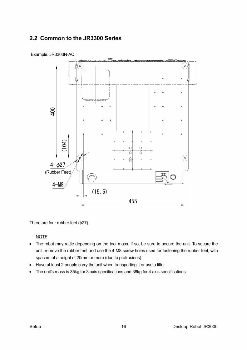
(Rubber Feet)
(104)
400
(15.5)
455
4-φ27
4-M8
Example: JR3303N-AC
2.2 Common to the JR3300 Series There are four rubber feet (ϕ27).
NOTE • The robot may rattle depending on the tool mass. If so, be sure to secure the unit. To secure the
unit, remove the rubber feet and use the 4 M8 screw holes used for fastening the rubber feet, with spacers of a height of 20mm or more (due to protrusions).
• Have at least 2 people carry the unit when transporting it or use a lifter. • The unit’s mass is 35kg for 3 axis specifications and 38kg for 4 axis specifications.
16

Setup Desktop Robot JR3000
(Rubber Feet)
(164)
502
(15.5)
551
4-φ27
4-M8
Example: JR3403N-AC
2.3 Common to the JR3400 Series There are four rubber feet (ϕ27).
NOTE • The robot may rattle depending on the tool mass. If so, be sure to secure the unit. To secure the
unit, remove the rubber feet and use the 4 M8 screw holes used for fastening the rubber feet with spacers of a height of 20mm or more (due to protrusions).
• Use a lifter to transport the unit. • The unit’s mass is 42kg for 3 axis specifications and 46kg for 4 axis specifications.
17
Setup Desktop Robot JR3000
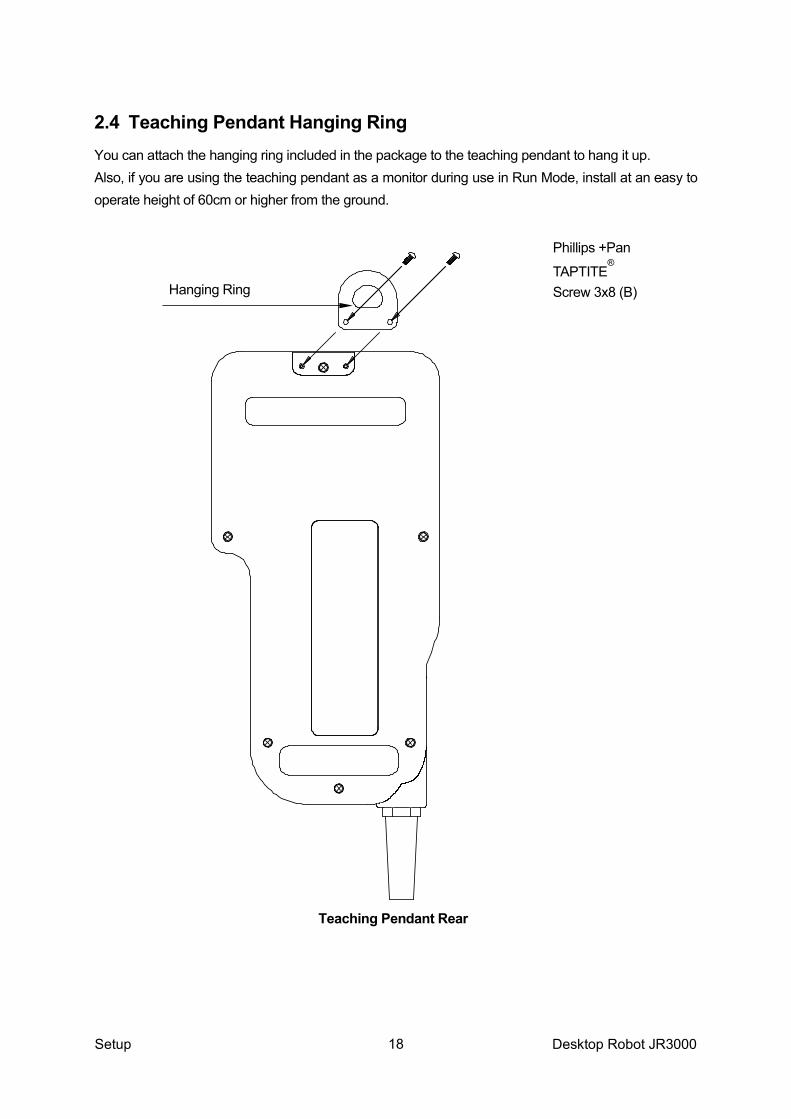
2.4 Teaching Pendant Hanging Ring You can attach the hanging ring included in the package to the teaching pendant to hang it up. Also, if you are using the teaching pendant as a monitor during use in Run Mode, install at an easy to operate height of 60cm or higher from the ground.
Phillips +Pan
TAPTITE®
Screw 3x8 (B) Hanging Ring
Teaching Pendant Rear
18
Setup Desktop Robot JR3000
2.5 Cable Connection
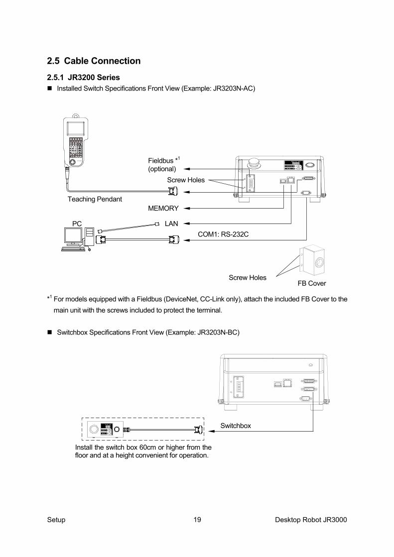
2.5.1 JR3200 Series � Installed Switch Specifications Front View (Example: JR3203N-AC)
*1 For models equipped with a Fieldbus (DeviceNet, CC-Link only), attach the included FB Cover to the
main unit with the screws included to protect the terminal. � Switchbox Specifications Front View (Example: JR3203N-BC)
Teaching Pendant
COM1: RS-232C PC
Fieldbus *1
(optional)
MEMORY
LAN
FB Cover
Screw Holes
Screw Holes
Switchbox
Install the switch box 60cm or higher from the floor and at a height convenient for operation.
19

Setup Desktop Robot JR3000
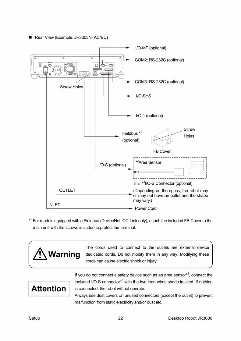
� Rear View (Example: JR3203N-AC/BC)
If you do not connect a safety device such as an area sensor*2, connect the included I/O-S connector*3 with the two lead wires short circuited. If nothing is connected, the robot will not operate. Always use dust covers on unused connectors (except the outlet) to prevent malfunction from static electricity and/or dust etc.
I/O-1 or I/O-MT(optional)
I/O-SYS
COM2: RS-232C (optional)
COM3: RS-232C (optional)
I/O-S (optional)
INLET
*3
*2
Power Cord
Area Sensor etc.
I/O-S Connector (optional)
Attention
20

Setup Desktop Robot JR3000
2.5.2 JR3300 Series � Installed Switch Specifications Front View (Example: JR3303N-AC)
� Switchbox Specifications Front View (Example: JR3303N-BC)
LAN
MEMORY
Teaching Pendant
COM1: RS-232C
Switchbox
Install the switch box 60cm or higher from the floor and at a height convenient for operation.
21
Setup Desktop Robot JR3000
� Rear View (Example: JR3303N- AC/BC)
*1 For models equipped with a Fieldbus (DeviceNet, CC-Link only), attach the included FB Cover to the
main unit with the screws included to protect the terminal.
If you do not connect a safety device such as an area sensor*2, connect the included I/O-S connector*3 with the two lead wires short circuited. If nothing is connected, the robot will not operate. Always use dust covers on unused connectors (except the outlet) to prevent malfunction from static electricity and/or dust etc.
I/O-1 (optional)
I/O-SYS
COM2: RS-232C (optional)
COM3: RS-232C (optional)
I/O-S (optional)
INLET
*2Area Sensor
Power Cord
I/O-MT (optional)
Fieldbus *1 (optional)
(Depending on the specs, the robot may or may not have an outlet and the shape may vary.)
FB Cover
Screw Holes
Screw Holes
OUTLET *3I/O-S Connector (optional)
Warning The cords used to connect to the outlets are external device dedicated cords. Do not modify them in any way. Modifying these cords can cause electric shock or injury.
Attention
22

Setup Desktop Robot JR3000
2.5.3 JR3400 Series � Installed Switch Specifications Front View (Example: JR3403N-AC)
� Installed Switchbox Specifications Front View (Example: JR3403N-BC)
LAN
MEMORY
Teaching Pendant
COM1: RS-232C
Switchbox
Install the switch box 60cm or higher from the floor and at a height convenient for operation.
23

Setup Desktop Robot JR3000
� Rear View (Example: JR3403N-AC/BC)
*1 For models equipped with a Fieldbus (DeviceNet, CC-Link only), attach the included FB Cover to the main unit with the screws included to protect the terminal.
If you do not connect a safety device such as an area sensor*2, connect the included I/O-S connector*3 with the two lead wires short circuited.. If nothing is connected, the robot will not operate. Always use dust covers on unused connectors (except the outlet) to prevent malfunction from static electricity and/or dust etc.
COM3: RS-232C (optional)
COM2: RS-232C (optional)
I/O-1 (optional)
I/O-SYS
I/O-S (optional)
OUTLET
INLET Power Cord
*3I/O-S Connector (optional)
I/O-MT (optional)
Fieldbus *1 (optional)
*2Area Sensor
(Depending on specs the robot may or may not have an outlet and the shape may vary)
Screw Holes
FB Cover
Screw Holes
Warning The cords used to connect to the outlets are external device dedicated cords. Do not modify them in any way. Modifying these cords can cause electric shock or injury.
Attention
24

Setup Desktop Robot JR3000
2.5.4 Device Connections For information regarding connecting an external device via I/O-SYS refer to the operation manual External Control (IO/Fieldbus), for LAN connections refer to “2.6 Connecting to a PC (Ethernet)” and for all other connections refer to the operation manual Specifications.
Connector Mark Connecting Cable Connecting Device
I/O-SYS I/O-SYS Cable Part name: I/O Cable (unit)
PLC, various tools, etc. Not included.
I/O-1 I/O-1 Cable Part name: I/O2 Cord (unit)
Various tools, etc. Not included
I/O-MT I/O-MT Cable Part name: I/OMT Optional Cord (unit)
Various tools, etc. Not included
COM1 RS-232C (Straight) D-SUB 9 Pin socket type Not included.
PC or PLC, etc. Not included.
COM2 COM3
RS-232C (Straight) D-SUB 9 Pin socket type Not included.
For extensions (camera, etc.) Not included
SWITCH BOX Integral to the switch box. Switchbox
TPU Integral to the teaching pendant. Teaching Pendant
I/O-S I/O-S connector Use the connector to create a safety circuit.
Area Sensor Safety Guard Switch etc. Not included.
INLET
Power cord Use an appropriate power cord for the power source you are using
Power source: Single-phase 90 – 125V 50/60Hz Power source: Single-phase 180 – 240V 50/60Hz
OUTLET
None
90 – 125V Connect the cord for the external device. Do not modify this cord.
The power supply specs are the same as the power supplied from the INLET. MAX: 3A 180 – 240V
LAN 100 BASE-TC, 10BASE-T PC
MEMORY -
USB 2.0 compatible memory. For information regarding USB memory usage, refer to “14. Memory Port” in Specifications.
NOTE The appropriate power cord varies depending on the model specifications.
25

Setup Desktop Robot JR3000
COMPATIBILITY WITH EC DIRECTIVES This robot is a semi-finished product, and includes a declaration to the EC directive. Janome implements its conformity testing via a third-party certification for each of the EMC, LCD, MD directives. The applicable requirements of the MD and EMC Directives vary depending on the machine settings and systems. We conduct general confirmation tests through a model setup. Please conduct final confirmation tests and risk assessments for your machine and its overall setup to make sure it conforms to the MD and EMC Directives.
2.5.5 Protective Grounding The power cord has an equipment grounding conductor and a grounding plug. Make sure to ground the robot using the power cord.
Warning Always make sure the machine is grounded through the power cord. Do not use the machine when it is not grounded. Improper grounding causes electric shocks, fires, malfunction, and unit breakdown.
Attention
26

Setup Desktop Robot JR3000
2.5.6 Attaching Devices Tie up air tubes and cables using the path illustrated below as a reference.
NOTE Make sure that each cable does not interfere with robot movements.
Cables for various devices
Air Tube
Various Devices
Cable Tie (included)
Bundle and tie up the air tubes, cords and cables with the cable ties.
Cord Clamp (included)
Fix the cord clamps in 3 places along the Y axis according to the size of the robot.
Z Stroke
Y Stroke
NOTE Tie up the cables so there is no stress on them when each of the axes run full-stroke.
Example: JR3403N-AC
27

Setup Desktop Robot JR3000
2.6 Connecting to a PC (Ethernet) To back up the robot’s C&T data and to upgrade the robot’s system software, connect the robot and a PC via Ethernet and make sure the PC and robot are able to interface. � Ethernet Overview The robot is fitted with an Ethernet connector (10/100BASE-TX) by standard. The LAN port is on the front of the robot. By using Ethernet to transmit commands and data from a PC, you can use functions such as the following: 1. Send and receive C&T data 2. Overwrite the system program 3. Online teaching such as JOG and GO movements etc. 4. Monitor functions such as external I/O and Fieldbus I/O display etc. 5. Set online settings such as administration settings and teaching environment settings etc. 6. Display robot information such as system information and error history etc. If using Ethernet, you can connect to and use multiple robots with one PC via a hub. With the PC software (JR C-Points II Limited Edition, or JR C-Points II) you can use functions such as the following: 1. Back up C&T data 2. Upgrade system software 3. Restore all data for when replacing printed circuit boards For further information, refer to the operation manual PC Operation.
Caution If you instruct an urgent stop from a network other than I/O-SYS, it takes a few moments for the robot to actually stop after the command is sent.
28

Setup Desktop Robot JR3000
2.6.1 JR C-Points II Limited Edition Requirements To operate JR C-Points II Limited Edition (included in the Operation Manual CD), the following system configurations are necessary: Computer A PC capable of running Windows® 7/8/8.1 Memory capacity 512MB or more
OS Microsoft Windows® 7/8/8.1 NOTE: compatible with both 32bit/64bit systems.
Hard disk capacity 2 GB or more free disk space after installing Windows® 7/8/8.1
LAN (Ethernet)
To connect to the robot, a LAN cable with the following specifications are required: • Straight cable (CAT5) The connectable Ethernet specifications (on the PC side) are as follows: • 10/100BASE-TX • LAN Port: RJ-45
The required memory capacity and hard disk capacity can vary depending on the PC’s system requirements. Also, take care when using a PC because if there is not enough free hard disk space, it can result in insufficient memory during operation or other such problems. � How to install JR C-Points II Limited Edition 1. Startup Windows® and confirm it is operating properly. Also close down any other open
applications. 2. Insert the Operation Manual CD into the CD-ROM drive. In the [JCP*E***L] folder (* =
specifications, *** = version number) double click [¥SETUP.EXE]. The installer starts up. 3. Follow the instructions on the screen and proceed with the installation.
NOTE If the installer is started up when the software is already installed, it will begin the uninstallation process. To uninstall JR C-Points II Limited Edition follow the same procedure as above to start up the uninstaller.
29

Setup Desktop Robot JR3000
LAN Port
Robot Front (Example: JR3203N-AC)
2.6.2 LAN Cable
Make sure power to both the robot and the PC are OFF before attaching or removing cables. Failure to do so can cause malfunction.
Use a straight LAN cable (category 5) compatible with the 10/100BASE-TX standard to connect the Robot and PC. Insert one end of the LAN cable into the LAN port on the robot and the other into the LAN port on the PC. If you are using JR C-Points II (optional) to operate the robot from the PC, please remove the teaching pendant. You cannot operate the robot with the teaching pendant connected. You cannot use a teaching pendant with an emergency stop switch (optional) unless a short connector is connected. � LAN Settings To get the robot and PC to interface, you need to setup an IP address on both the robot side and PC side. For further details please refer to “2.6.5 Robot IP Address Settings” and “2.6.6 IP Address Settings on the PC”.
Attention
30

Setup Desktop Robot JR3000
2.6.3 LAN Port Diagram: RJ-45
LAN Port Pin Assignment Pin No. Name Function 1 TD+ Transmit signal+ 2 TD- Transmit signal- 3 RD+ Receive signal+ 4 NC Not connected 5 NC Not connected 6 RD- Receive signal- 7 NC Not connected 8 NC Not connected
2.6.4 Communication Settings (IP Address Settings) Ethernet communication uses “TCP/IP protocol”. For this reason, you need to set the IP address, subnet mask, and default gateway as preparations for Ethernet connection. These settings are done using the PC software, JR C-Points II Limited Edition. JR C-Points II Limited Edition is included on the Operation Manual CD. You can set the IP address from your PC using Ethernet. To set the IP address via Ethernet, you need to establish communication settings (TCP/IP settings) on the PC side. Please take note of the following points for PC communication settings (TCP/IP). • To use Ethernet functions, you need a TCP/IP network environment. • If you are using the default network settings, you do not need to set a new IP address on the PC. • Do not use a DHCP server as the robot uses a static IP address. • If you are setting a new IP address on the PC, please consult your network administrator.
8 1
31

Setup Desktop Robot JR3000
2.6.5 Robot IP Address Settings You can set up the robot’s IP address from the PC software JR C-Points II (optional). (This is also possible with Limited Edition) Open the JR C-Points II robot IP address settings dialog by clicking [Robot] Æ [IP-Address Settings]. • IP Address (initial settings: 192.168.200.180) • Subnet Mask (initial settings: 255.255.255. 0) Enter these values and click the [Setting] button to send the settings to the robot. Turn the power to the robot OFF and then ON again to apply the new settings. You can also set up the robot IP address settings from the teaching pendant. Connect the teaching pendant, and turn the power to the robot ON. Display the screen; [Administration Mode] Æ [Administration Settings Mode] Æ [Ethernet Settings] and make the following settings: • IP Address (initial settings: 192.168.200.180) • Subnet Mask (initial settings: 255.255.255. 0) Turn the power to robot OFF and then ON again to apply the new settings.
NOTE After modifying the settings and exiting [Administration Settings Mode], the system is reset and the settings are enabled.
2.6.6 PC IP Address Settings Set the IP address if the IP address is not already set on the PC. Set the IP address with IPv4 as the robot is not compatible with IPv6. If the IP address is already set, you do not need to set the IP address again. • The IP address setting method varies depending on the Windows® version you are using. Set the
IP address by referring to the manual supplied with your PC. • For the IP address, we recommend using a class C private IP address (192.168.0.0 –
192.168.255.255). However, you cannot set 0 and 255 to the right end of the IP address (4th octet). • If you want to set a new IP address to the PC, contact your network administrator.
32

Setup Desktop Robot JR3000
3. BACKING UP AND RESTORING ROBOT DATA
The robot (data) storage area is partitioned as shown by the diagram on the right. All of the storage area partitions, including the robot system software storage partition, are subject to backup and data restoration operations. Make sure to create backup data in case of contingencies. To create backup data, startup JR C-Points II Limited Edition on the PC, receive data from the robot, and then save the received data as a file. 3.1 Backup Data The robot system software, C&T data, individual configuration information and model setting files held by the robot are read and saved as a file. If you do not specify an extension, the file is saved as a “JRB” extension file. Select [Backup Robot Data] from the [Robot] pull-down menu to display the dialog below. Click the file icon and specify the name of the backup file and the location where you want to save it. An existing file can also be specified. Click [Backup] to start the backup operation. After the backup is complete, restart the robot.
Individual configuration information varies for each individual unit even if they are the same model. Do not use backup data with a different robot. The robot cannot function normally with backup data from a different robot.
Caution
Specify the backup file
Individual Configuration Info.
C&T Data
Robot System Software
Storage Area
Model Setting Files
33

Setup Desktop Robot JR3000
3.2 Restore Data This restores robot data using the data saved in [Robot Data Backup]. Restoring robot data deletes all of the data in the robot (robot system software, C&T data, individual configuration information and model setting files) and overwrites it with the data in the backup file. Click [Robot] on the menu bar and select [Restore Robot Data] from the pull-down menu. The dialog to the right is displayed. Click the [Open File] icon, specify the backup file and click [Restore]. After the restoration is complete, restart the robot.
3.3 Backing Up and Restoring Data via USB Memory You can also use USB memory to make a data backup. Refer to “1.1 Backing Up and Upgrading via USB Memory” in Maintenance for details on how to use USB memory.
Individual configuration information varies for each individual unit even if they are the same model. Do not use backup data with a different robot. The robot cannot function normally with backup data from a different robot.
Caution
34

Setup Desktop Robot JR3000
4. SENDING AND RECEIVING C&T DATA
The data sent and received between the robot and the PC is teaching data and customizing data, sent as one unit (C&T data).
NOTE To create backup data using a PC, refer to “2.6 Connecting to a PC (Ethernet)” in this manual, and “2.2 Connecting to a PC (LAN Connection)” in Maintenance and make sure the robot and PC are able to interface.
The robot has a data storage area and a work area. When you start the robot, the C&T data in the storage area is copied to the work area. Data in the work area is used for teaching and running programs. The data in the work area is deleted when the power to the robot is turned OFF. When receiving data from the robot, the PC receives work area data. If sending data from the PC to the robot, the sent data is automatically written to the storage area via the work area.
NOTE If you are using JR C-Points II (optional), you can also perform the same operation by selecting [Receive C&T Data] from the [Robot] pull-down menu in JR C-Points II.
Example: JR3203N-AC Send/Receive
Data PC
Backup Data
Storage Area Work Area
35

Setup Desktop Robot JR3000
Have the robot doing one of the following: Switch Run Mode: Waiting for run start (Wait Start Point) External Run Mode: Waiting for run start (Wait Start Point) Teaching Mode: Point value setting screen Startup JR C-Points II Limited Edition, and from the [Robot] pull down menu select [Receive C&T Data]. To create a backup file, click the [Receive] button. The C&T data transfer starts. Once the transfer of C&T data is complete, “The C&T Data was Received Successfully” message appears on the screen. Note that the C&T data is not displayed on the screen. Save the file by selecting [Save as] from the [File] pull down menu. If you send a backup file to the robot using [Send C&T Data], the robot will revert back to the received data. Click [Segment Receive] to select and receive a specific program or customizing datum etc. For example, when the backup file is open, select just one program with [Segment Receive] and only that received program is updated. With [Segment Receive], you can update the robot’s C&T data for only a specific program, etc.
36

Setup Desktop Robot JR3000
5. TRANSMITTING ROBOT SYSTEM SOFTWARE
This robot is controlled by built-in robot system software. To upgrade the robot system software or make a system recovery due to the robot not starting up properly, follow the instructions below. (The robot system software version number can be confirmed through the version information display described in “10. Checking Version Information” in Maintenance. The robot system software is included on the operation manual CD-ROM under the following file name: � JR3_SysProgram_V.+++_***.jsy
(“+++” indicates the version number. “***” varies according to robot specifications.) There are two methods of downloading the system software; downloading using the PC software, or downloading using USB memory. This section explains about the method using the PC software. For information regarding the method using USB memory, please refer to “1.2 Write System Software” in Maintenance. 1. Turn ON the robot and startup JR C-Points II Limited Edition on the PC. 2. In the menu bar select [Robot] and then click [Send Robot System Software] from the pull down
menu. The dialog below is displayed: 3. When upgrading, select [Version Update] as the Transmission Mode. If restoring the system
software, select [Recovery] as the Transmission Mode. (The robot IP address used for recovery is 192.168.200.180. For application specifications, after making a recovery, transfer the system software once more by selecting [Version Update].)
4. Click [Open], specify the drive where the Operation Manual CD is inserted, then select the [Robot System Software] file and click [Open]. The selected file name is displayed. Click [Send] and the robot system software transmission begins.
5. After the transmission, turn the robot OFF and then ON again.
37

Setup Desktop Robot JR3000
NOTE • To perform this operation, the robot and PC must be connected. Refer to “2.6 Connecting to a PC
(Ethernet)” and make sure the robot and PC can interface. • If you are using JR C-Points II software (optional), the robot system software can also be upgraded
by selecting [Send Robot System Software] from the [Robot] pull-down menu.
38

Setup Desktop Robot JR3000
6. CLOCK SETTINGS
Before you first use the robot, set up the clock settings. Once you set up clock settings, the robot can record the date and time of when errors occur. You can set this with the teaching pendant or PC software (optional). For setting up clock settings via the teaching pendant, press the MODE key and switch over to the Administration Mode. From [Administration Settings Mode], select and set up [Clock Settings].
MODE [Administration] [Administration Settings Mode]
[Clock Settings]
[Robot] Æ [Administration] Æ [Clock Settings] With clock settings, after entering each value for the year, month, day, time, minute, and second, the information is registered to the robot by selecting [Clock Setup]. If the information is registered correctly, the screen reverts to the Administration Settings Mode screen. The error history screen can be viewed by using one of these procedures:
Administration Æ [Error History] Teaching Mode Æ UTILITY Æ [Error History] Run Mode Æ MENU Æ [Error History]
Administration Settings Mode Start Channel I/O-SYS Change Program Number COM Settings Ethernet Settings Fieldbus Settings MEMORY Port Settings Back Light Auto OFF Clock Settings Clear Error History Clear All C&T Data Reset Teaching Environment Settings Reset Administration Settings
TP
PC
TP
39

Setup Desktop Robot JR3000
TCP-X View from above
View from the side
Tool Position During Teaching
Current Tool Position
TCP-Y
7. SETTINGS NEEDED FOR TEACHING
Before registering a program etc. matchup the following settings to the methods and environment with which you will use the robot. 7.1 3-Axis Specifications: Tool Data The following settings are in [Tool Data]: • Tool Mass (the mass affecting the Y axis) • TCP-X: The X direction distance from the tool tip during teaching to the current tool tip • TCP-Y: The Y direction distance from the tool tip during teaching to the current tool tip • TCP-∆Z: The Z direction distance from the tool tip height during teaching to the current tool tip
height The offset value for the offset from the tool tip is referred to as the tool center point (TCP). � Tool Mass This [Tool Mass] refers to the total mass of the tool and of the object which the tool is holding. Make sure this mass is equal to or lower than the registered mass. � TCP-X, TCP-Y For 3 axes specifications, TCP-X and TCP-Y are set with the teaching tool weight and the current tool weight offset (the offset amount for the X direction and Y directions). With [Direct TCP-XY Setting], you can automatically calculate (subtract) and set the offset by indicating a registered point when changing tools during teaching. For 3 axes specifications, it is not necessary to set the TCP-X and TCP-Y in advance. Teach with the 0,0 setting as is, and if there is a tool tip offset when you change tools etc., set that difference for the first time then.
Caution If the tool mass is heavier than the registered settings, a position error may occur.
40

Setup Desktop Robot JR3000
� TCP-∆Z After changing tools etc., if the tool height is different from the registered tool center point position, enter the Z-direction difference to TCP-∆Z.
NOTE: When adding a new program, the values of the default all program common settings (customizing data) are entered as program data default values.
Additionally, when using the additional function data [Tool Data], you can change tool data at intervals between specific points. For example, it is possible to change the registered tool mass settings for only the period of time it is gripping something.
MENU [Individual Program Settings] [Tool Data]
NOTE: When the bottommost item shown is highlighted, press the CURSOR key to display the other settable items for that point.
[Program] Æ [Individual Program Settings] Æ [Tool/Workpiece] Æ [Tool Data]
7.2 4-Axis Specifications: Tool Data The following settings are in [Tool Data]: • Tool Mass (mass affecting the Y axis) • TCP-X: The X direction distance from the R axis center to the tool tip. • TCP-Y: The Y direction distance from the R axis center to the tool tip. • TCP-∆Z: The Z direction distance from the tool tip height during teaching to the current tool tip
height. The offset value for the offset from the tool tip is referred to as the tool center point (TCP). � Tool Mass [Tool Mass] refers to the total mass of the tool and of the object which the tool is holding. Make sure this mass is equal to or lower than the registered mass. The settings are as follows: Tool Mass
1 2 3 JR3200 1 kg 3.5 kg JR3300, JR3400 1 kg 4 kg 7 kg
TP
PC
Caution If the tool mass is heavier than the registered settings, a position error may occur.
41

Setup Desktop Robot JR3000
� TCP-X, TCP-Y The TCP (tool center point) is the X and Y direction distance from the R axis center to the tool tip. With [Direct TCP-XY Setting], you can automatically calculate and set the [TCP-X] and [TCP-Y] values by indicating the same point twice with the tool tip (from different R-axis angles). For 4 axes specifications, make sure to set tool data (TCP-X, Y) before teaching programs. If you perform program teaching etc. without setting tool data, you will have to repeat teaching all of the coordinates whenever you change tools. If the tool tip exceeds the acceptable moment of inertia, a position error may occur. Tool Tip Moment of Inertia JR3200 65kg/cm2 JR3300, JR3400 90kg/cm2
� TCP-∆Z After changing the tool etc., if the tool tip height is different from the registered tool center point position, enter the Z-direction difference to TCP-∆Z.
NOTE When adding a new program, the values for the default all program common settings (customizing data) are entered as program data default values.
Additionally, when using the additional function data [Tool Data], you can change tool data at intervals between specific points. For example, it is possible to change the registered tool mass settings for only the period of time it is gripping something.
MENU [Individual Program Settings] [Tool Data]
NOTE: When the bottommost item shown is highlighted, press the CURSOR key to display the other settable items for that point.
[Program] Æ [Individual Program Settings] Æ [Tool/Workpiece] Æ [Tool Data]
TP
PC
TCP-Y
TCP-X
Top View
Side View
Tool Tip R Axis Center
42

Setup Desktop Robot JR3000
7.3 Workpiece Mass There is no [Workpiece Mass] setting for the JR3200. This is fixed at 7kg. For other models, the default for [Workpiece Mass] is 5kg.
NOTE With the PC software (JR C-Points II) this item is not available and cannot be modified.
Set [Workpiece Mass] using the table below. Tool Mass
1 2 3 JR3200 7 kg JR3300, JR3400 5 kg 10 kg 15 kg
NOTE If you use a workpiece mass heavier than the settings, a position error may occur.
Teaching Mode MENU [Individual Program Settings]
[Workpiece Mass] NOTE: When the bottommost item shown is highlighted, press the CURSOR key to display
the other settable items for that point.
MENU [All Program Common Data] [Workpiece Mass]
Customizing Mode [Teaching Mode Customizing]
[All Program Common Default Settings] [Workpiece Mass]
[Program] Æ [Individual Program Settings] Æ [Tool/Workpiece] Æ [Workpiece Mass]
[Data] Æ [All Program Common Settings] Æ [Tool/Workpiece] Æ [Workpiece Mass]
[Set T.M.C] Æ [Default All Program Common Settings] Æ [Tool/Workpiece] Æ [Workpiece Mass]
TP
PC
PC
PC
TP
TP
43

Setup Desktop Robot JR3000
8. SETTINGS NEEDED TO MAKE A RUN
Before running a point or program, match up the following settings to the methods and environment with which you will use the robot. 8.1 External Run Mode Settings If using the robot in External Run Mode, set the source from where the entered start signal becomes valid. The start signal can only be made valid in one place. If sending the start signal from I/O-SYS, a run start from COM 1 is not recognized. If you want to direct a run start from COM1, set to COM 1.
MODE [Administration] [Administration Settings Mode]
[Start Channel]
[Robot] Æ [Administration] Æ [Administration Settings] Æ [General Setting] • I/O-SYS
Turn ON #sysIn1 (I/O-SYS) and the run starts. • Fieldbus
Turn ON #fbIn1000 (Fieldbus) and the run starts. For details regarding Fieldbus, refer to External Control (I/O / Fieldbus).
• COM1
Send a run start command from COM1 and the run starts. For command details, refer to the operation manual Communication Control (COM/LAN).
• User Definition
When set to [User Definition], the robot cannot be started up from either I/O-SYS, Fieldbus or COM1. With system programs you can expect to use this setting not for performing program starts and/or axis movements, but for performing programs and/or axis movements according to Run Mode jobs set by the user. In this situation, it is the user’s responsibility to make sure there is only one start channel. Once set to [User Definition], callProg and movement commands are recognized in Run Mode operations.
TP
PC
44

Setup Desktop Robot JR3000
• Ethernet Send a run start command via Ethernet and the run starts. The receiving port on the robot side is 10031. For further information regarding commands, refer to Communication Control (COM/LAN).
8.2 Setting Program Numbers Here you can set the method for changing program numbers. 8.2.1 Changing Program Numbers To change program numbers, there are 5 methods shown below. These methods can be restricted. • The teaching pendant PRG.NO key. • The program selection keys (operation switches) on the front of the robot • A signal input via COM1 • A signal input via I/O-SYS • A signal input via Fieldbus • A signal input via Ethernet For example, if you set COM1 to [Valid] and the others to [Invalid], changing program numbers is only possible through the PC, and you can no longer change program numbers from the teaching pendant or the selection keys (operation switches) on the front of the robot, etc.
MODE [Administration] [Administration Settings Mode]
[Changing Program Number]
[Robot] Æ [Administration] Æ [Administration Settings] Æ General Setting] 8.2.2 Program Number Reading Format You can select whether the signal that matches I/O signal program numbers 1 – 512 is read as [Binary] or [BCD]. If using [BCD], program numbers 1 – 8 are assigned to the ones place, numbers 16 – 128 are assigned to the tens place, and numbers 256 – 512 are assigned to the hundreds place.
NOTE If specifying from I/O-SYS when 128 or more [Binary], or 80 or more [BCD] program numbers are set, you must switch the “#sysIn11 – sysIn13” signal function to “Program Number” (I/O-SYS function assignment).
TP
PC
45

Setup Desktop Robot JR3000
MENU [All Program Common Settings] [I/O Settings]
[Program Number Reading Format]
[Data] Æ [All Program Common Settings] Æ [Common Data] 8.2.3 Program Number Switching Method If you want to change program numbers by connecting a digit switch to the I/O terminal, select [Load at Start].
Selection Description
LOAD/ACK Handshake
When the Program Number LOAD Signal comes ON, the status of the I/O Signal Program Number 1 – 512 is loaded (for the Fieldbus, the status of the program number register is loaded), the Program Number ACK signal is output, and the program number changes.
Load at Start (I/O-SYS) When the start instruction is received, the status of the I/O signal program number 1 – 512 is loaded, and the program number changes.
Load at Start (Fieldbus) When the start instruction is received, the status of the program number register is loaded, and the program number changes.
NOTE: Program Number 1 – 64 signals are loaded under the default [Program Number Switching
Method] settings. If you wish to use the Program Number 128/256/512 signal, you need to change the signal function in the [I/O-SYS Function Assignment] settings.
MENU [All Program Common Settings]
[I/O Settings] [Program Number Switching Method]
[Data] Æ [All Program Common Settings] Æ [Common Data]
Program Number LOAD Signal
Program Number 1 – 512
Program Number ACK Signal
Acquire ACK
LOAD
Acquire
Program Number 1 – 512
Start Signal
LOAD/ACK Handshake Load at Start
TP
PC
TP
PC
46

Setup Desktop Robot JR3000
8.3 I/O-S Settings (Optional) The I/O-S is a connector intended for use with an area sensor or a light curtain etc. If the signal from this connector comes ON during a run, the robot makes an emergency stop. It is possible to restrict the emergency stop so it does not occur if the I/O-S signal comes ON when the robot is in standby.
Robot Status I/O-S Function Settings Action When the Signal from I/O-S goes ON
Running Emergency Stop Makes an emergency stop Interlock Makes an emergency stop occurs
Standby Emergency Stop Makes an emergency stop occurs Interlock Doesn’t make an emergency stop
MENU [All Program Common Settings] [I/O Settings]
[I/O-S Function Settings]
[Data] Æ [All Program Common Settings] Æ [Common Data]
TP
PC
47

Setup Desktop Robot JR3000
9. CONVERTING JR2000/JR2000N DATA TO JR3000 DATA
To use JR2000/JR2000N series teaching data as JR3000 series C&T data, it is necessary to convert the data. The following three steps are needed to convert data: 1. Use JR Points (JR2000 optional) and/or JR C-Points (JR2000N optional) to send the data to the
PC. 2. Open the data received from step 1 using JR C-Points II*. 3. Send the data from the PC to the JR3000 using JR C-Points II*.
*In place of JR C-Points II (optional), JR C-Points II Limited Edition (included in the Operation Manual CD) can also be used to convert data.
NOTE It is possible to connect one PC to both a JR2000/JR2000N Series robot and a JR3000 Series robot at the same time. You can also connect a PC to the JR2000/JR2000N Series robot, receive the data, disconnect the JR2000/JR2000N robot, and then connect the JR3000 Series robot. (To convert data using one PC, JR-Points or JR C-Points and JR C-Points II must be installed on the PC.)
Teaching Data
Connect Connect
JR2000/JR2000N Example: JR2203N
PC(JR-Points/ JR C-Points) PC(JR C-Points II) JR3000 Series
Example: JR3203N-AC
Caution Make sure to turn OFF the robot before removing or connecting cables. Failure to do so may cause unit malfunction or data loss.
48

Setup Desktop Robot JR3000
Please carry out the following: (This is done using a PC with JR-Points or JR C-Points and JR C-Points II installed and connected to both the JR2000/JR2000N and JR3000 Series robots.) 1. Turn ON the robot and the PC. If the robot is in Run Mode, make sure it is in run standby. For other
modes, have the robot at the base screen. 2. On the PC, boot up JR-Points for the JR2000 Series or JR C-Points for the JR2000N Series. Set
the port to match the COM port connected to the JR2000/JR2000N Series robot. [Robot] Æ [COM Status]
3. Transfer the teaching data from the JR2000/JR2000N Series robot.
[Robot] Æ [Receive C&T Data] 4. Name the data and save it. For JR-Points, the file is saved as an “.rps” extension. For JR C-Points,
the file is saved as an “.cps” extension [File] Æ [Save As]
5. Exit JR-Points or JR C-Points and start up JR C-Points II. 6. In Ethernet Settings, register the JR3000 Series robot to where you want to send data.
[Robot] Æ [Ethernet Settings] 7. From the [Open] dialog box, change [File Type] to [JR Points File (*.rps)] for the JR2000 Series, or
change to [JR C-Points File (*.cps)] for the JR2000N Series. Open the data file sent from the JR2000/JR2000N Series robot.
[File] Æ [Open] 8. Transfer the data to the JR3000 Series robot.
Caution: when data is transferred from the PC to the robot, any data stored in the robot is deleted and overwritten with the newly transferred data.
[Robot] Æ [Send C&T Data]
NOTE • For the JR-Points operating environment etc., refer to the JR-Points operation manual. • For the JR C-Points operating environment etc., refer to the JR C-Points operation manual.
PC
PC
PC
PC
PC
PC
49

Setup Desktop Robot JR3000
� Precautions when converting from JR-Points to JR C-Points II • The sysFlag numbers for point jobs, execute conditions, PLC programs etc., do not change when
they are converted over from JR-Points, however, contents of some items have changed with JR C-Points II. Please confirm after converting over to JR C-Points II.
� Precautions when converting from JR C-Points to JR C-Points II • Point job numbers 101 – 200 for JR C-Points are, depending on Protect Mode, converted as
follows: Point job numbers of items in [No Limit] and [Public] Protect Mode do not change. For this reason, these items can be run as they are. Items in [Protected] and [Private] Protect Mode are converted with +400 added to their point job number to protect the defined content. For this reason, these items cannot be run as they are. Please amend this data.
• With JR C-Points II, TPIF (Port 4) has been removed from the COM ports. For this reason, items which are specified to TPIF (Port 4) in JR C-Points are converted to COM 1. However, point jobs are not converted, so please amend this data.
• The various display order of T.M.C settings are not converted.
50

Janome Sewing Machine Co., Ltd. Industrial Equipment Sales Division
1463 Hazama-machi, Hachioji-shi, Tokyo, Japan, 193-0941 Tel: +81-42-661-6301 Fax: +81-42-661-6302
The specifications of the machine and/or the contents of this manual may be modified without prior notice to improve quality. No part of this manual may be reproduced in any form, including photocopying, reprinting, or translation into another language, without the prior written consent of JANOME.
©2014, Janome Sewing Machine Co., Ltd., All rights reserved. Japanese Ver. 2014-10
170803104 as of 2014-10
www.metermixdispense.com
866 967 4660