james r. de fries | architectural portfolio
DESCRIPTION
Professional PortfolioTRANSCRIPT

JAMES R. DE FRIES | ARCHITECTURAL PORTFOLIO


My name is James Richard De Fries; my journey on the path of architecture began with helping my father finish our basement at home and participating in many high school art classes. I pursued this interest by attending wood shop, drafting, and architectural classes. I became increasingly interested in the profession because I saw a great potential to use architecture to improve the lives of the world’s population. My true passion in life helping those in need and making life better for the community through creative design and problem solving. My faith in God motivates me to do the best work I am capable of doing and to achieve many goals in life.

Studio 804: August 2015 to May 2016Collaborating with peers to design and build a LEED Platinum residence in less than a year.
Epic Fun Family Fun Center Drafter: Summer 2014Completed as-built floor plans and re-designed a retail space to properly fit an arcade and laser tag arena.
Velocity Church Graphic Designer: January 2013 to January 2014Designed way-finding signs, Church apparel, and pamphlets.
Camp Barnabas Cabin Councilor: May to June 2013Partnered with people with disabilities to provide unique experiences and to spur oncreativity and adaptability.
Helpers Inc. Tutor: August to December 2013Assisted children with disabilities to improve communication and social skills and promoted awareness of disabilities.
World Market Sales Associate August 2014 to July 2015Interacted with customers and team members on the floor to sell merchandise and organized stock.
James R. De Fries | Master Of Architecture Candidate 2016Phone: (660) 238-9023Email : jdefries1991@gmail .com
Professional Experience

Church Operations Leader: February 2014 to July 2015Created a welcoming and fun atmosphere in the church.
Family Promise Volunteer: August 2014 to PresentAssisted families get back on their feet through the avenue of friendship and cooking.
Jubilee Cafe: August 2014 to PresentHelped nourish low-income and homeless men, women, and children.
Volunteer Work
Master of Architecture, University of Kansas, anticipated graduation May 2016
Minor In Business, University of Kansas, anticipated graduation May 2016
Skills and Proficiencies:
Education:

1200 Pennsylvania St.
Donald Judd Museum
Build Design Dining Pavilion
Timberwolves Stadium
Free Hand Drawing

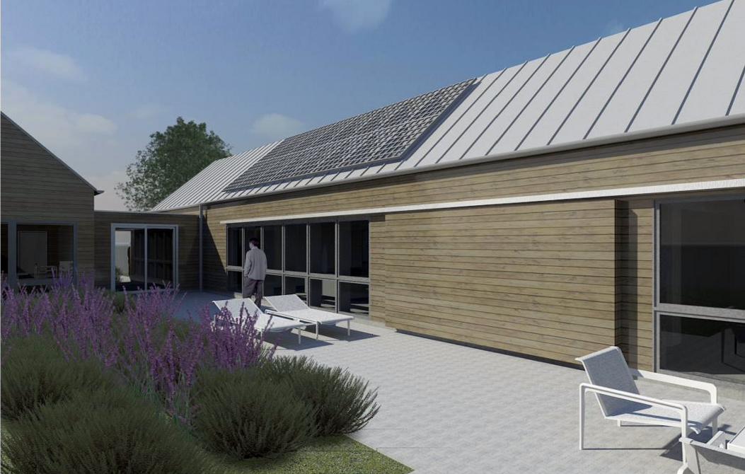
1200 Penn. is a project that was designed and constructed by a group of graduate students from the University of Kansas as a last year option. Located on the corner of Pennsylvania and 12th Street, the house occupies a lot-and-a-half allowing for a design that could not be accomplished in the traditional lot width of East Lawrence. 1200 Pennsylvania will utilize the lot-and-a-halfsize by creating a courtyard and extruding twoforms east and west to maximize the home’s southern exposure utilizing passive solar design. The goal of the project and Studio 804 is to achieve LEED Platinum certification through intelligent and incorporated green design. This layout incorporates a courtyard overlooking a bioswale. Every room within the house has views that focus on these two elements.
120
0 P
ENN
SYL
VAN
IA S
T.


Penn
sylv
ania
Str
eet
12th Street


DW
METAL FLASHING
2" XPS
12" CONCRETE FIBER BOARDAROUND PERIMETER4" CRUSHED AGGREGATE
4" FIBER REINFORCED CONCRETESLAB WITH #4 @ 2'x2' o.c.
15-MIL VAPOR BARRIER
AGGREGATE INFILL
1/2" ANCHOR BOLT
2"x6" TREATED WOOD SILL PLATESILL SEALANT
#4 REBAR @ 4' o.c.
(2) #4 REBAR CONTINUOUS
2'-6
"2'-0
"
0'-6
"
JOINT SEALANT ANDBACKER ROD WITH SHIMMETAL FLASHING2" XPS
12" CONCRETE FIBER BOARDAROUND PERIMETER
CRUSHED AGGREGATE
5 1/2" CONCRETE SIDEWALK
#4 REBAR @ 4' o.c.
(2) #4 REBAR CONTINUOUS
4" FIBER REINFORCED CONCRETESLAB WITH #4 @ 2'x2' o.c.
15-MIL VAPOR BARRIER
AGGREGATE INFILL
2'-6
"2'-0
"
0'-6
"
METAL FLASHING2" XPS12" CONCRETE FIBER BOARDAROUND PERIMETER4" CRUSHED AGGREGATE
4" FIBER REINFORCED CONCRETESLAB WITH #4 @ 2'x2' o.c.
15-MIL VAPOR BARRIER
AGGREGATE INFILL
1/2" ANCHOR BOLT2"x6" TREATED WOOD SILL PLATESILL SEALANT
#4 REBAR @ 4' o.c.(2) #4 REBAR CONTINUOUS
2'-6
"
6" Ø ERV DUCT
2'-0
" 3' - 0"
DUCT SLOPED TOWARD INTERIOR 1/8" : 1'
2' - 8 1/2"
3'-6
"11
'-0"
6' - 0" 2' - 8"
6" Ø ERV EXHAUST6" Ø ERV SUPPLY
TUB SUPPLY
FLOOR DRAIN
RADON VENT
TOILET SUPPLY
SINK SUPPLY
TOILET SUPPLY
SINK SUPPLY
PANEL CONDUIT
4" CONCRETE SLAB ON GRADE
REFRIGERATOR SUPPLY
SINK SUPPLY
WASHER SUPPLY
4" CONCRETE SLAB ON GRADE
6" Ø ERV EXHAUST 6" Ø ERV SUPPLY
9'-4
1/4"
EDGE OF CONCRETE SLAB
1'-0
"
TUB BOXTUB BOX
SHOWER DEPRESSION
11' - 5 3/4"
10' - 6"
5'-8
1/2"
SHOWER SUPPLY
1' - 7"
1'-4
1/2"
3'-0
"
7'-8
"
1'-9
1/2"
11' - 1 3/4"
7'-1
"
ALT. SUPPLY
0'-6
1/2"
4" CONCRETESLAB ON GRADE
4" CONCRETESLAB ON GRADE
3" PVC MainService (30" Under)(Westar ServiceStandard ss-40.5)
1" PVC Solar Disconnect
1" PVC Solar DisconnectLED DRIVER PANEL (16"ABOVE COMM. PANEL)
3/4" PVC(18" UNDER)
1 1/4" PVC (CONDUITTO GARAGE) (18"UNDER)Table 300.5 NEC
1 1/4" PVC(CONDUIT TOGARAGE) (18"UNDER)
1" PVC for Communications Entrance
1"
1"
1"
2"
1 1/4"
1 1/
4"
1 1/
4"
3/4"
5" Ø PVCFLOOR BOX
3/4"
3/4"
1"
1"1"
COMM. PANEL(20" ABOVE SLAB)
3/4"
3/4" 4'-9
1/4"
5'-8
1/4"
6'-6
1/2"
8'-2
3/4"
7'-6
3/4"
6' - 6 1/4"
4'-4
3/4"
1'-0
"
1' - 6 1/2"
2' - 10 1/4"
16'-
0"
8'-0
"
1' - 4" 3' - 0"
2'-8
1/2"
6'-6
1/2"
19' - 4 1/4"
11' - 2"
10' - 10"
17' - 3 3/4"
8'-8
1/4"
8'-3
"
20' - 11 1/2"
17' - 6"
18' - 9 1/4"
23' - 11 1/2"
0'-9
3/4"
16' - 8"
0'-9
3/4"
14'-
41/
2"
6' - 10 1/4"
1'-1
3/4"
12' - 6 1/4"
10' - 0"
8'-1
03/
4"
4' - 0"
7' - 6"
11' - 6 1/2"
12' - 5 1/2"
6' - 5 1/2" 46' - 0 1/2"
34' - 2"
19' - 10"
18' - 6 3/4"
14' - 1 3/4"
7'-5
"
4' - 3 1/2"
5'-0
"
8'-7
"
2'-0
1/2"
SINK SUPPLY
7'-4
"
8'-7
"
9'-1
0"
25' - 11"
Copyright © 2015 Studio 804, Inc.
Description:
Penn
sylv
ania
Stre
et R
esid
ence
University of KansasSchool of Architecture Designand Planning1465 Jayhawk BoulevardMarvin HallLawrence, KS 66045(p) 785.864.4024www.studio804.com
Schematic Design
Date:
1200
P enn
sylv
ania
Stre
etLa
wre
n ce,
KS66
046
D
C
B
A
D
C
B
A
12345
12345
C102FOUNDATION SLAB
09/16/15
1" = 1'-0" D1FOUNDATION TO STUD 1" = 1'-0" D2FOUNDATION TO GLAZING
1" = 1'-0" D3FOUNDATION HVAC CONDITION
1/4" = 1'-0" A1FOUNDATION SLAB PLAN

KITCHEN
GUEST BEDROOM
MASTER BEDROOMLIVING ROOMMECH.BATH
ADA BATH
GARAGE
STORMSHED


LEVEL 10' - 0"
T.O. EXT. WALL9' - 9"
T.O. WINDOW6' - 8"
FROST LINE-2' - 6"
2" x 10" RIM JOIST
DOUBLE 2" x 6" TOP PLATE
BLOWN-IN CELLULOSEBETWEEN 2" x 6" STUDS@ 16" O.C.
1/2" GYPSUM WALLBOARD
1/2" OSB SHEATHING
2" RIGID INSULATIONW/ INTEGRATEDMOISTURE MEMBRANE
RAIN SCREEN SYSTEM
2" x 6" TREATED BASE PLATE
BLOWN-IN CELLULOSEBETWEEN 2" x 10" RAFTERS
@ 16" O.C.
2" x 10" JOISTS @ 16" O.C.
SCB BYPASS FRAMING CLIPTHERMALLY BROKEN FROMSHEATHING
5" GUTTER WITH RIPPED 2x2TREATED BLOCKING
RAIN SCREEN ON 1" RIPPEDTREATED MATERIAL ONS-5CLIPS
DROP AND DOWNSPOUTBEYOND
1/2" GYPSUM WALLBOARD
FLASHING
1/2" OSB SHEATHING
STANDING SEAM METAL ROOF
C102D1
F.F. LEVEL 20' - 0"
F.F. LEVEL 39' - 9"
F.F. LEVEL 46' - 8"
F.F. LEVEL 5-2' - 6"
Countertop3' - 0"
T.O. GARAGE EXT.WALL7' - 9"
9 3/
4"
A143D4
1' - 0"
1' - 6"
LEVEL 10' - 0"
T.O. EXT. WALL9' - 9"
T.O. WINDOW6' - 8"
FROST LINE-2' - 6"
C102D2
A131A4
2" x 10" RIM JOIST
DOUBLE 2" x 6" TOP PLATE
BLOWN-IN CELLULOSEBETWEEN 2" x 6" STUDS@ 16" O.C.
1/2" GYPSUM WALLBOARD
ALUMINUM WINDOW FLASHING (BEYOND)
RAIN SCREEN SYSTEM (BEYOND)
BLOWN-IN CELLULOSEBETWEENN. 2" x 10" RAFTERS
@ 16" O.C.
2" X 10" JOISTS @ 16" O.C.
1/2" GYPSUM WALLBOARD
FLASHING
1/2" OSB SHEATHING
STANDING SEAM METAL ROOF
BARN DOORTRACK SYSTEM
F.F. LEVEL 20' - 0"
A143C4
CEDAR FURRING STRIP (BEYOND)
4" OSB BACKED INSULATION
PEERLESS WINDOW ASSEMBLY
BARN DOOR ASSEMBLY
A131B4
T.O. WINDOW6' - 8"
TOLERANCE1/2"
6 1/
4"
F.F. LEVEL 39' - 9"
2 1/
4"
Copyright © 2015 Studio 804, Inc.
Description:
Penn
sylv
ania
Stre
et R
esid
ence
University of KansasSchool of Architecture Designand Planning1465 Jayhawk BoulevardMarvin HallLawrence, KS 66045(p) 785.864.4024www.studio804.com
Schematic Design
Date:
1200
P enn
sylv
ania
Str e
etLa
wre
n ce,
KS
6604
6
D
C
B
A
D
C
B
A
12345
12345
A131WALL SECTIONS
08/31/15
3/4" = 1'-0" A1TYP. CONDITION WALL SECTION 3/4" = 1'-0" A2TYP. WALL SECTION THRU WINDOW
1 1/2" = 1'-0" B4BARN DOOR TRACK - WINDOW CONDITION
1 1/2" = 1'-0" A4T.O. EXTERIOR WALL


----
----
----
A
B
C
DE
16" O.C.
16"O
.C.
16" O.C. 16" O.C.
----
----
----
----
16' - 8"
3' - 4"
(2) 2" x 4" HEADERS
0' - 5 1/2" 0' - 5 1/2"
(2) 1 3/4" X 16" LVL HEADERS
2"X4" NAILER2"X4" NAILER 2"X6" NAILER 2"X4" NAILER 2"X6" NAILER
16" O.C.
2"X4" NAILER
16" O.C.
16" O.C.
6'-8
"
16" O.C. 16" O.C.
16' - 0" 10' - 0 1/2" 18' - 8" 16' - 0" 8' - 4 1/2"
59ST
UDS
(NO
NA
ILERS
)
1' - 3"
----
9'-4
1/2"
END STUD FROM EAST WALL,NAIL TO ABUTTING STUD W/16D 24" O.C.
----
----
16" O.C.
(2) 1 3/4" X 16" LVL HEADER
2" X 6" ACQ BASE
(2) 2" X 10" HEADER
18' - 6"
16' - 8"
16' - 0"10' - 8"
6' - 8"
1' - 4"
1' - 4" 1' - 4"
1' - 4"
2"x4" NAILER STUD
37ST
UDS
(NO
NA
ILERS
)
7' - 0 1/2"
1' - 4"
16" O.C.16" O.C.16" O.C.
9'-4
1/2"
9'-9
"
10' - 1"
2"x6" NAILER
9'-9
"
8'-0
"
16" O.C.
1' - 4"1' - 4"
14ST
UDS
(3) 2X10 HEADER
9'-4
1/2"
2"x4" NAILER
0' - 6 1/4" 0' - 1 3/4"1' - 4"
----
Copyright © 2015 Studio 804, Inc.
Description:
Penn
sylv
ania
Stre
et R
esid
ence
University of KansasSchool of Architecture Designand Planning1465 Jayhawk BoulevardMarvin HallLawrence, KS 66045(p) 785.864.4024www.studio804.com
Schematic Design
Date:
1200
P enn
sylv
ania
Stre
etLa
wre
n ce,
KS66
046
D
C
B
A
D
C
B
A
12345
12345
S104FRAMINGPLAN_EXTERIOR
09/14/15
3/8" = 1'-0" 2NORTH FRAMING PLAN
3/8" = 1'-0" 1FRAMING PLAN - S104
3/8" = 1'-0" BNORTH WALL FRAMING
3/8" = 1'-0" 7COURTYARD FRAMING DETAIL
3/8" = 1'-0" DCOURTYARD FRAMING ELEVATION 3/8" = 1'-0" EENTRY NORTH FRAMING


The award winning KU Armitage Center Dining Pavilion is a collaborative third year studio design/build project. The conceptual design for the project was to have five walls that slope upwards, gradually getting taller, as if they were rising from the ground and out of the wheat fields of Kansas. This was important to our mission to provide the Armitage Center clients because they provide students an area to study soils, native plant species, and native wildlife and insects. The axis of the project was determined by a pre existing path to the entry of the Armitage Center which makes one feel like they are embraced by the center.
KU A
RMIT
AGE
PAVI
LIO
N
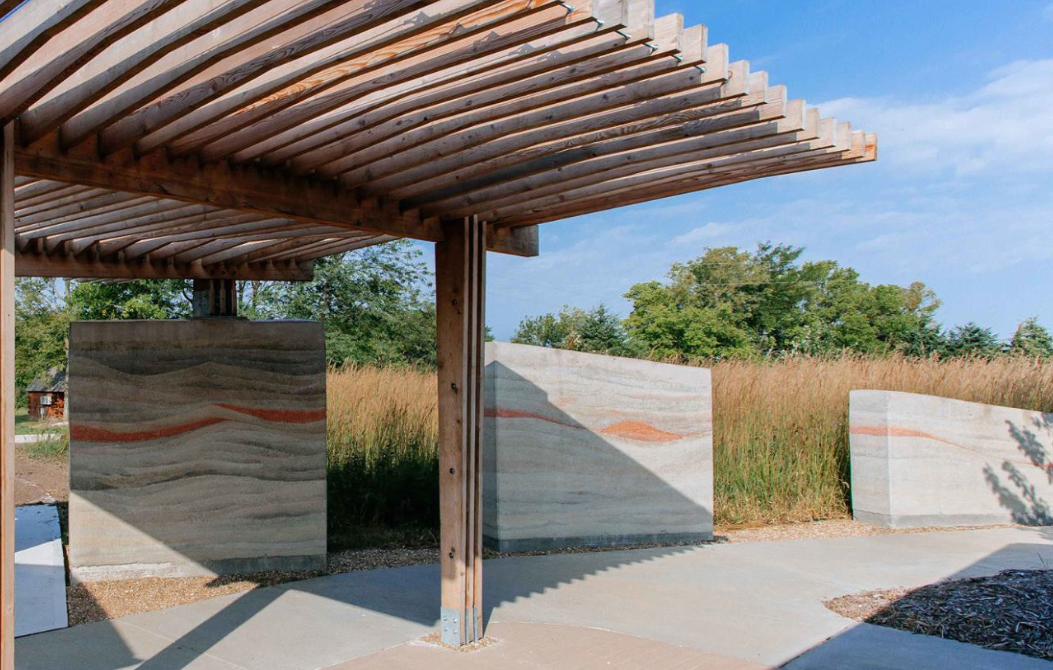


The bulk of the labor for this project resided in the construction of the rammed earth walls. To build a rammed earth wall one has to have the right amount of aggregate, cement, water, and dye. These items are mixed together in a cement mixer and then poured into a wheel barrow for more hand mixing to get the perfect consistency. It is then carried up a ramp in buckets and poured into form-work with a rebar cage which has been placed in a foundation wall. It is then rammed with a piston power by diesel until it is solid. This process is repeated for each layer, or lithe, with a different color until all the colors are laid out as desired.


The canopy was designed to emphasize tall prairie grass that grows next to the pavilion. It is to resemble the wind that blows throw the prairie grass resulting in .


“The limits of Architecture are its strength. Its inability to give form to a transient idea, its inevitable tendency to stabilize,
is the latent power of Architecture.”
-David Chipperfield


Steel Lanyard Mounting TabSteel Turnbuckle
Steel Cable11 Gauge Steel Straps
Carved wooden Louver MemberFrom Recycles Telephone Pole 2”x10”
3/8” Threaded Steel RodWood Structural Beam Sistered From
Recycled Telephone Pole 2x10”Wood Structural Column From
Recycled Telephone Pole 2” x 10”3 Gauge Steel Brackets
Reinforced Rammed Earth WallsReinforced Concrete Bell Footing

4

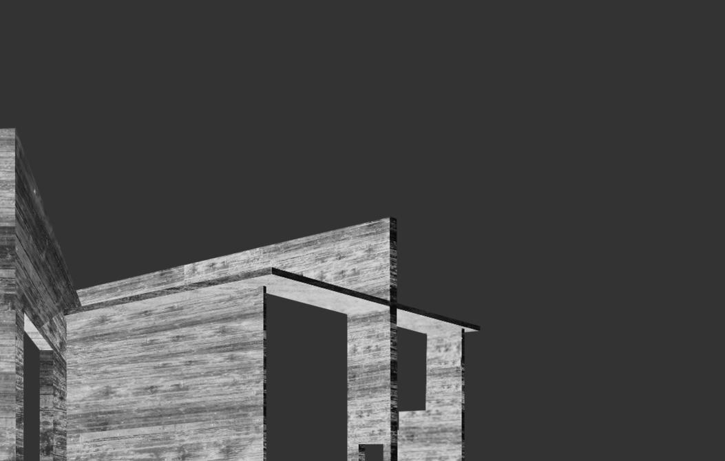
Inspired by Tadao Ando’s exceptional attention to space and light, this project was the perfect opportunity to combine the brilliance of Tadao Ando with the beautiful simplicity of Donald Judd’s art work to form a pragmatic Museum. The Donald Judd Museum is formed by a language of planes that separate the spaces into permanent art installations, by Judd, and interchangeable art installations created by the local population. The two-story high curtain wall systems allow a view to the surrounding area of the up and coming downtown Kansas City. The museum is to be an entity that makes one feel welcomed, feel enlightened, and feel inspired.
DO
NA
LD J
UD
D M
US
EUM


Conservation Room
DN
DN
UP
DN
DN
DN
DN
UP
UP
A DC E HF G
1
2
3
4
5
6B
DN
A DC E HF G
1
2
3
4
5
6B
Second Floor PlanScale: 1/8”=1’
First Floor PlanScale: 1/8”=1’
Basement Floor PlanScale: 1/8”=1’
Mechanical Room
Storage Woodshop
Library
Welcome Center/Reception Area
Temporary Gallery
CafeBathroom
Bathroom
DNPermanent Gallery
Permanent Gallery
Permanent Gallery
O�ce/Kitchenette/Conference
Temporary Gallery
A
A
B B
C C
A
A
B B
CCBathroom
Loading Dock
A DC E HF G
1
2
3
4
5
6B
A
A
B B
C C
N N N

1 2 3 4
1. TPO Roo�ng2. Roof Insulation3. 11” Concrete Slab4. #5 Reinforcing Bar5. End Jamb Mullion6. Curtain Wall7. Railing8. Mullion9. 1’ Thick Concrete Slab10. #6 Reinforcing Bar11. Beams12. 2“ Thick Gypsum Cieling
13. Cast-In-Place Sidewalk14. Re�ecting Pool15. Water-Proo�ng Membrane16. 6” Concrete Slab17. Gravel18. Earth19. Structural Bracket
20. Earth21. Water-Proo�ng Membrane22. Retaining Wall23. #5 Reinforcing Bar24. Drain Gravel25. Drain Pipe
26. 1’ Concrete Slab27. #6 Reinforcing Bar28. Rigid Insulaiton29. Vapor Barrier30. Gravel31. Foundation Earth
5
6
7
8
9 10 11 12
26 27 28 29 30 31
13 14 15 16 17 18 19
20
21
22
23
24
25
Donald Judd Wall SectionStudio 408James De FriesNilou Vakil
1. TPO Roofing2. Roof Insulation3. 11” Concrete Slab4. #5 Reinforcing Bar5. End Jamb Mullion6. Curtain Wall7. Railing8. Mullion9. 1’ Thick Concrete Slab10. #6 Reinforcing Bar11. Beams12. 2” Thick Gypsum Ceiling
13. Cast-in-Place14. Reflecting Pool15. Water-Proofing Membrane16. 6” Concrete Slab17. Gravel18. Earth19. Structural Bracket
20. Earth21. Water Proofing Membrane22. Retaining Wall23. #5 Reinforcing Bar24. Drain Gravel25. Drain Pipe26. 1’ Concrete Slab27. #6 Reinforcing Bar28. Rigid Insulation29. Vapor Barrier30. Gravel31. Foundation Earth

North ElevationScale: 1/8”=1’
W.
19TH
STREET
CENTRAL
STREET
West ElevationScale: 1/8”=1’

North ElevationScale: 1/8”=1’
W.
19TH
STREET
CENTRAL
STREET
West ElevationScale: 1/8”=1’
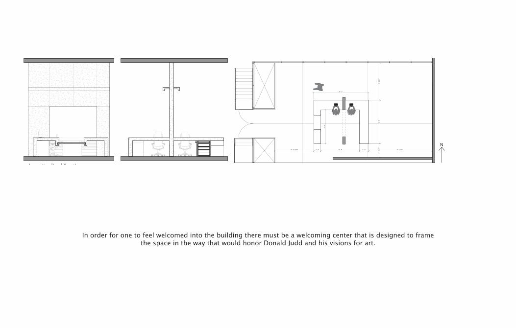
Longitudinal SectionScale: 1/2”=1’
Transverse SectionScale: 1/2”=1’
Desk PlanScale: 1/2”=1’
10' - 8" 17' - 3 3/4"2' - 6"2' - 0"10' - 8 19/32"
9' -
4"
10' -
2 3
/4"
12' -
0"
3' -
10 3
/4"
15' - 2"
N
Donald Judd Museum Reception DeskJames De FriesStudio 408Nilou Vakil
In order for one to feel welcomed into the building there must be a welcoming center that is designed to frame the space in the way that would honor Donald Judd and his visions for art.


The goal of our design was to provide a central hub in Minneapolis, Minnesota that celebrates its team and the movement around the city. We did this by making the people of the city feel like they are apart of the wolf pack through various design implementations and branding of our general and premium admission spaces. There a a total of 9 premium spaces that were designed to cater fresh foods and experiences that brought the crowds from home and into the arena. The influence for the skin of the stadium was created from and abstraction of wolf fur. We did this to make the fans, figuratively, feel like they are inside the wolf and could be apart of the wolf pack.
TIM
BER
WO
LVES
STA
DIU
M

Merchandise

An important aspect to the Minneapolis life style is the skyway system which helps people get around the city when it is cold outside. The skyway system is an extensive system that connects many buildings together and which also host various pop-up stores and permanent vendors. We used the skyway systems as one of the main entries to the arena so that it is celebrated as an architectural element as well as a mode of transportation.


South Elevation


3 42 5 3231DED E CC BBA A
Scale: 1/32” = 1’Longitudinal Section
08_Catwalk
03_Roof Call Out
02_Skin Call Out
01_Entry Level Call Out
04_Mediamesh Call Out
07_Twin City Wolf Club
06_Upper Concourse
05_Double Decker Suite Level
04_Suite Mezz. 1
03_Main Concourse
02_Entry Level
01_Event Level
95’ - 8 1/8”
77’ - 4 1/4”
59’ - 11 1/4”
42’ - 8 1/4”
30’ - 2 1/4”
16’ - 4 1/4”
0’ - 0”
-11’ - 7 3/4”

Triple Pane Window
Terrazzo Floor
Rieder Oko Skin
Reclaimed Wood
Concrete Pavers
Cement Board


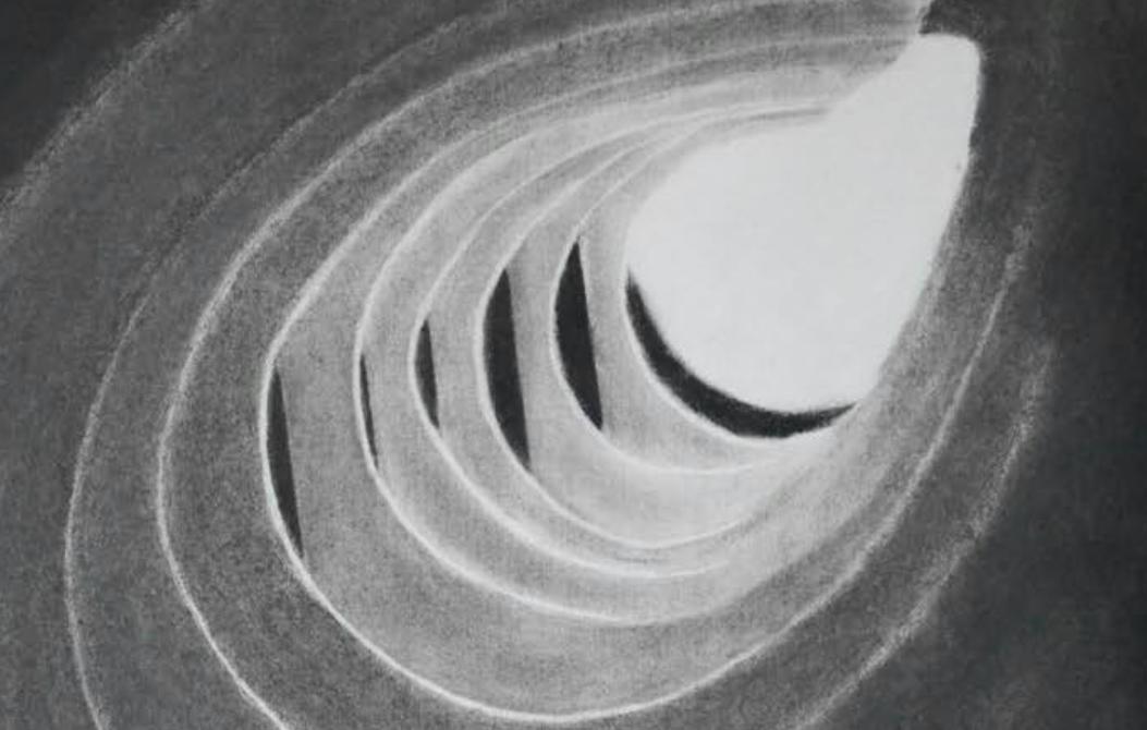
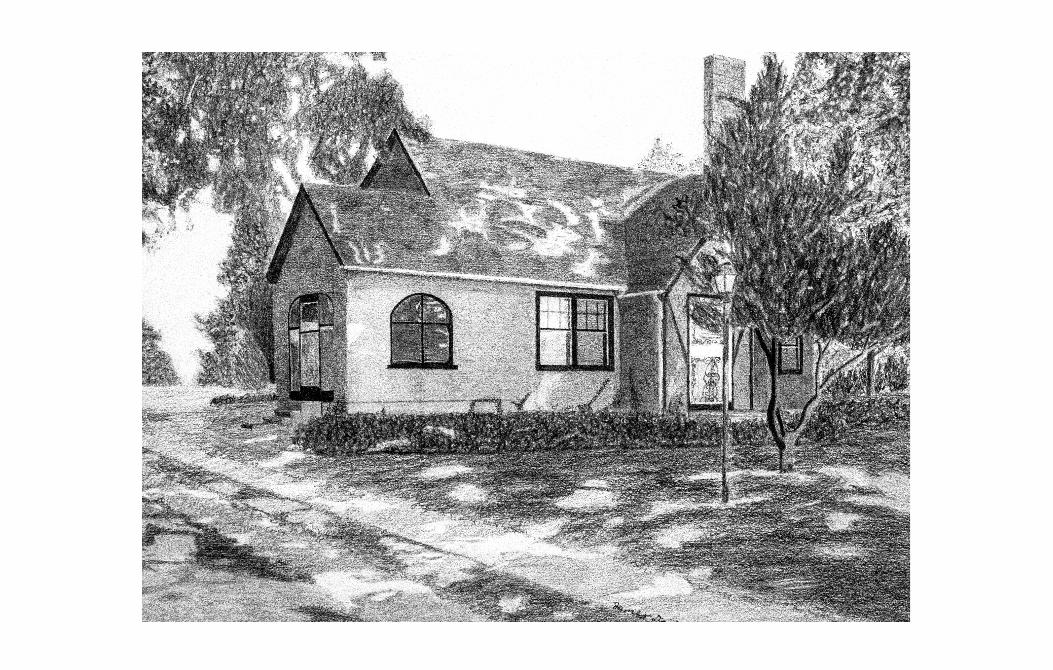
“I prefer drawing to talking. Drawing is faster and leaves less room for lies”
-Le Corbusier
FREE
HAN
D DR
AWIN
G


T H A N K Y O U
