jaipur institute of technology- group of …
TRANSCRIPT

JIT/ME/V SEM / MECHATRONICS LAB
JAIPUR INSTITUTE OF TECHNOLOGY- GROUP OF INSTITUTIONS
JAIPUR
MECHATRONICS LABORATORY
III B.TECH (Mechanical): V SEMESTER
DEPARTMENT OF MECHANICAL ENGINEERING

JIT/ME/V SEM / MECHATRONICS LAB

JIT/ME/V SEM / MECHATRONICS LAB
Lab Important Instructions:
1. Lab reports must be submitted immediately at the end of the lab session. Late
submission will not be entertained on any account.
2. Flowcharts must be drawn neatly.
3. All observations and programs should be hand written neatly using a pen.
Answers written using pencil will not be evaluated.
4. Avoid attaching printouts.
5. Individual reports must be submitted for all the lab experiments.
6. Plagiarism will be treated very seriously.
7. Use of hand phones and gadgets inside the lab is strictly prohibited.

JIT/ME/V SEM / MECHATRONICS LAB
Ex. No:
Introduction To Mechatronics
Page No. Date :
OBJECTIVE:
At the end of the lab session, students will have the knowledge of definition
and elements of mechatronics system, apply the principles of mechatronics and
automation for the development of productive and efficient manufacturing systems,
the hydraulic and pneumatic systems employed in manufacturing, and learn the
CNC technology as applications of mechatronics in manufacturing automation.
What is Mechatronics?
Mechatronics is a concept of Japanese origin (1970’s) and can be defined as
the application of electronics and computer technology to control the motions of
mechanical systems
Fig Definition of Mechatronics
It is a multidisciplinary approach to product and manufacturing system
design Fig It involves application of electrical, mechanical, control and computer
engineering to develop products, processes and systems with greater flexibility,
ease in redesign and ability of reprogramming. It concurrently includes all these
disciplines.

JIT/ME/V SEM / MECHATRONICS LAB
Fig Mechatronics a multi-disciplinary approach
Mechatronics can also be termed as replacement of mechanics with electronics
or enhance mechanics with electronics. For example, in modern automobiles,
mechanical fuel injection systems are now replaced with electronic fuel injection
systems. This replacement made the automobiles more efficient and less pollutant.
With the help of microelectronics and sensor technology, mechatronics systems are
providing high levels of precision and reliability. It is now possible to move (in x – y
plane) the work table of a modern production machine tool in a step of 0.0001 mm.
By employment of reprogrammable microcontrollers/microcomputers, it is now
easy to add new functions and capabilities to a product or a system. Today’s
domestic washing machines are “intelligent” and four-wheel passenger automobiles
are equipped with safety installations such as air-bags, parking (proximity) sensors,
anti- theft electronic keys etc.
MECHATRONICS SYSTEM
A system can be thought of as a box or a bounded whole which has input and
output elements, and a set of relationships between these elements. Figure 1.1.4
shows a typical spring system. It has ‘force’ as an input which produces an
‘extension’. The input and output of this system follows the Hooke’s law F = –kx,
where F is force in N, x is distance in m and k is stiffness of the spring.

JIT/ME/V SEM / MECHATRONICS LAB
Fig A spring force system
Fig Constituents of a mechatronics system
A Mechatronics system integrates various technologies involving sensors,
measurement systems, drives, actuation systems, microprocessor systems and
software engineering. Figure 1.1.5 shows the basic elements of a mechatronics
system. Consider the example of a simple spring-mass system as shown in figure
To replace the mechanics of this mechanical system with an equivalent
mechatronics based system, we need to have the basic controlling

JIT/ME/V SEM / MECHATRONICS LAB
element, a

JIT/ME/V SEM / MECHATRONICS LAB
microprocessor. Microprocessor processes or utilizes the information gathered
from the sensor system and generates the signals of appropriate level and suitable
kind (current or voltage) which will be used to actuate the required actuator viz. a
hydraulic piston-cylinder device for extension of piston rod in this case. The
microprocessor is programmed on the basis of the principle of Hooks’ Law. The
schematic of microprocessor based equivalent spring mass system is shown in
figure 1.1.6.
Fig Microprocessor based equivalent spring mass system
The input to the system is a force which can be sensed by suitable electro-
mechanical sensors viz. piezo-electric device or strain gauges. These sensors
generate either digital signals (0 or 1) or analogue signals (milli-volts or milli-
amperes). These signals are then converted into right form and are attenuated to a
right level which can properly be used by the microprocessor to take generate the
actuation signals. Various electronics based auxiliary devices viz. Analogue-to-
Digital Converter (ADC), Digital-to-Analogue Converter (DAC), Op-amps,
Modulators, Linearization circuits, etc. are used to condition the signals which are
either received by the microprocessor from the sensors or are sent to the actuators
from the microprocessor. This mechatronics based spring-mass system has the
input signals in the digital form which are received from the ADC and Piezo-electric
sensor. The digital actuation signals generated by the microprocessors are
converted into appropriate analogues signals. These analogue signals operate the
hydraulic pump and control valves to achieve the desired displacement of the
piston-rod.

JIT/ME/V SEM / MECHATRONICS LAB
APPLICATIONS
Mechatronics has a variety of applications as products and systems in the
area of ‘manufacturing automation’. Some of these applications are as follows:
1. Computer numerical control (CNC) machines
2. Tool monitoring systems
3. Advanced manufacturing systems
a. Flexible manufacturing system (FMS)
b. Computer integrated manufacturing (CIM)
4. Industrial robots
5. Automatic inspection systems: machine vision systems
6. Automatic packaging systems
COMPUTER NUMERICAL CONTROL (CNC) MACHINES
CNC machine is the best and basic example of application of Mechatronics in
manufacturing automation. Efficient operation of conventional machine tools such
as Lathes, milling machines, drilling machine is dependent on operator skill and
training. Also a lot of time is consumed in work part setting, tool setting and
controlling the process parameters viz. feed, speed, depth of cut. Thus conventional
machining is slow and expensive to meet the challenges of frequently changing
product/part shape and size.
Computer numerical control (CNC) machines are now widely used in small to
large scale industries. CNC machine tools are integral part of Computer Aided
Manufacturing (CAM) or Computer Integrated Manufacturing (CIM) system. CNC
means operating a machine tool by a series of coded instructions consisting of
numbers, letters of the alphabets, and symbols which the machine control unit
(MCU) can understand.
These instructions are converted into electrical pulses of current which the
machine’s motors and controls follow to carry out machining operations on a work
piece. Numbers, letters, and symbols are the coded instructions which refer to
specific distances, positions, functions or motions which the machine tool can
understand.

JIT/ME/V SEM / MECHATRONICS LAB
Fig Comparison between a conventional machine tool and a CNC
machine tool
CNC automatically guides the axial movements of machine tools with the help
of computers. The auxiliary operations such as coolant on-off, tool change, door
open- close are automated with the help of micro-controllers. Figure 1.2.1 shows the
fundamental differences between a conventional and a CNC machine tool. Manual
operation of table and spindle movements is automated by using a CNC controllers
and servo motors. The spindle speed and work feed can precisely be controlled and
maintained at programmed level by the controller. The controller has self
diagnostics facility which regularly alarms the operator in case of any safety norm
violation viz. door open during machining, tool wear/breakage etc. Modern machine
tools are now equipped with friction-less drives such as re-circulating ball screw
drives, Linear motors etc. The detail study of various elements of such a
Mechatronics based system is the primary aim of this course and these are
described at length in the next modules.

JIT/ME/V SEM / MECHATRONICS LAB
Ex. No: Simple Arithmetic Operations
Page No. Date :
Objective:
At the end of the lab session, students will have the knowledge on how to write an assembly language program to add, subtract, the given data stored at two consecutive locations using 8085 microprocessor.
Question 1: Write an assembly language program to add, the given data stored at
two consecutive locations using 8085 microprocessor.
Program:
Address Mnemonics Operand Opcode Remarks
4000 LXI H, 3000H 21 Load H-L pair with address 5000H.
4001 00 Lower-order of 5000H.
4002 50 Higher-order of 5000H.
4003 MOV A, M 7E Move the 1st
operand from memory to reg. A.
4004 INX H 23 Increment H-L pair.
4005 MOV B, M 46 Move the 2nd
operand from memory to reg. B.
4006 ADD B 80 Add B with A.
4007 INX H 23 Increment H-L pair.
4008 MOV M, A 77 Move the result from reg. A to memory.
4009 HLT 76 Halt.
Question 2: Write an assembly language program to subtract, the given data stored
at two consecutive locations using 8085 microprocessor.
Program:
Address Mnemonics Operand Opcode Remarks
4000 LXI H, 3000H 21 Load H-L pair with address 5000H.
4001 00 Lower-order of 5000H.
4002 50 Higher-order of 5000H.
4003 MOV A, M 7E Move the 1st
operand from memory to reg. A.
4004 INX H 23 Increment H-L pair.

JIT/ME/V SEM / MECHATRONICS LAB
4005 MOV B, M 46 Move the 2nd
operand from memory to reg. B.
4006 SUB B 90 Subtract B from A.
4007 INX H 23 Increment H-L pair.
4008 MOV M, A 77 Move the result from reg. A to memory.
4009 HLT 76 Halt.
Question 3: Write an assembly language program to find the largest of two given
data using 8085 microprocessor.
Program:
Address Mnemonics Operand Opcode Remarks
4000 LXI H, 3000H 21 Load H-L pair with address 5000H.
4001 00 Lower-order of 5000H.
4002 30 Higher-order of 5000H.
4003 MOV A, M 7E Move the 1st
operand from memory to reg. A.
4004 INX H 23 Increment H-L pair.
4005 MOV B, M 46 Move the 2nd
operand from memory to reg. B.
4006 CMP B B8 Compare B with A.
4007 JNC 200BH D2 Jump to address 400BH if there is no carry.
4008 0B Lower-order of 400BH.
4009 20 Higher-order of 400BH.
400A MOV A, B 78 Move largest from reg. B to reg. A.
400B INX H 23 Increment H-L pair.
400C MOV M, A 77 Move the result from reg. A to memory.
400D HLT 76 Halt.
Question 4: Write an assembly language program to find the smallest of two given
data using 8085 microprocessor.
Program:
Address Mnemonics Operand Opcode Remarks
4000 LXI H, 3000H 21 Load H-L pair with address 5000H.
4001 00 Lower-order of 5000H.

JIT/ME/V SEM / MECHATRONICS LAB
4002 50 Higher-order of 5000H.
4003 MOV A, M 7E Move the 1st
operand from memory to reg. A.
4004 INX H 23 Increment H-L pair.
4005 MOV B, M 46 Move the 2nd
operand from memory to reg. B.
4006 CMP B B8 Compare B with A.
4007 JC 200BH DA Jump to address 400BH if there is no carry.
4008 0B Lower-order of 400BH.
4009 20 Higher-order of 400BH.
400A MOV A, B 78 Move smallest from reg. B to reg. A.
400B INX H 23 Increment H-L pair.
400C MOV M, A 77 Move the result from reg. A to memory.
400D HLT 76 Halt.
REPORT EVALUATION
S.no
Description
Weightage
Marks
Awarded
1 Program 40
2 Execution 30
3 Results 10
4 Viva-voce 20
Total 100

ME 6712 MECHATRONICS LABORATORY-LAB MODULE 3
Ex. No:
Stepper Motor Interface
Page No. Date :
Objective:
At the end of the lab session, students will have the knowledge how to execute a program using micro controller kit to run a stepper motor at different angles,
run in forward and reverse directions alternatively.
Apparatus Required
8051 Micro controller kit.
Key broad.
Stepper motor.
Procedure:
Switch on the micro controller
Engage the control DIP switch
Feed the opcode to the micro controller kit through the keyboard.
Execute the program using the GO command.
The output of the program is verified from the stepper motor rotation.
Question 1: For the following write a program to run a stepper motor in clockwise
direction
Program:
MEMORY ADDRESS OBJECT CODES MNEMONICS
4100 7C MOV R4. #FF
4101 FF
4102
90 START: MOV DPTR, #
LOOK UP
4103 41
4104 14
4105 78 MOV R0, #04

ME 6712 MECHATRONICS LABORATORY-LAB MODULE 3
4106 04
4107 E0 JO: MOVX A, @DPTR
4108 C0 PUSH DPH
4109 83
410A C0 PUSH DPL
410B 82
410C 90 MOV DPTR, #FFCOH
410D FF
410E C0
410F F0 MOVX @DPTR, A
4110 DC DJNZ R4, CALL
4111 06
4112 80 HLT: SJMP HLT
4113 FE
4114
09 LOOK UP: DB 09H, 05H,
06H, 0AH
4115 05
4116 06
4117 0A
4118 7A CALL: MOV R2, #03
4119 03
411A 79 DLY2: MOV R1, #FFH
411B FF
411C 7B DLY1: MOV R1, #FFH
411D FF
411E DB DLY: DJNZ R3, DLY
411F FE
4120 D9 DJNZ R1, DLY1
4121 FA

ME 6712 MECHATRONICS LABORATORY-LAB MODULE 3
4122 DA DJNZ R2, DLY2
4123 F6
4124 D0 POP DPL
4125 82
4126 D0 POP DPH
4127 83
4128 A3 INC DPTR
4129 D8 DJNZ R0, JO
412A DC
412B 80 SJMP START
412C D5
412D END
Question 2: For the following write a program to run a stepper motor in anticlockwise
direction
Program:
MEMORY ADDRESS OBJECT CODES MNEMONICS
4100 7C MOV R4. #FF
4101 FF
4102
90
START: MOV DPTR, #
LOOK UP
4103 41
4104 14
4105 78 MOV R0, #04
4106 04
4107 E0 JO: MOVX A, @DPTR

ME 6712 MECHATRONICS LABORATORY-LAB MODULE 3
4108 C0 PUSH DPH
4109 83
410A C0 PUSH DPL
410B 82
410C 90 MOV DPTR, #FFCOH
410D FF
410E C0
410F F0 MOVX @DPTR, A
4110 DC DJNZ R4, CALL
4111 06
4112 80 HLT: SJMP HLT
4113 FE
4114
0A
LOOK UP: DB 0AH, 06H,
05H, 09H
4115 06
4116 05
4117 09
4118 7A CALL: MOV R2, #03
4119 03
411A 79 DLY2: MOV R1, #FFH
411B FF
411C 7B DLY1: MOV R1, #FFH

ME 6712 MECHATRONICS LABORATORY-LAB MODULE 3
411D FF
411E DB DLY: DJNZ R3, DLY
411F FE
4120 D9 DJNZ R1, DLY1
4121 FA
4122 DA DJNZ R2, DLY2
4123 F6
4124 D0 POP DPL
4125 82
4126 D0 POP DPH
4127 83
4128 A3 INC DPTR
4129 D8 DJNZ R0, JO
412A DC
412B 80 SJMP START
412C D5
412D END

ME 6712 MECHATRONICS LABORATORY-LAB MODULE 3
Question 3: For the following write a program to run a stepper motor in 360° clockwise
direction
MEMORY ADDRESS OBJECT CODES MNEMONICS
4101 C8
4114
09
LOOK UP: DB 09H, 05H,
06H, 0AH
4115 05
4116 06
4117 0A
Question 4: For the following write a program to run a stepper motor in 360°
anticlockwise direction
MEMORY ADDRESS OBJECT CODES MNEMONICS
4101 C8
4114
0A
LOOK UP: DB 09H, 05H,
06H, 0AH
4115 06
4116 05
4117 09
Question 5: For the following write a program to run a stepper motor in 270° clockwise
direction
MEMORY ADDRESS OBJECT CODES MNEMONICS
4101 96
4114
09
LOOK UP: DB 09H, 05H,
06H, 0AH
4115 05
4116 06
4117 0A
Question 6: For the following write a program to run a stepper motor in 270°
anticlockwise direction
MEMORY ADDRESS OBJECT CODES MNEMONICS
4101 96
4114
0A
LOOK UP: DB 09H, 05H,
06H, 0AH

ME 6712 MECHATRONICS LABORATORY-LAB MODULE 3
4115 06
4116 05
4117 09
Question 7: For the following write a program to run a stepper motor in 180° clockwise
direction
MEMORY ADDRESS OBJECT CODES MNEMONICS
4101 64
4114
09
LOOK UP: DB 09H, 05H,
06H, 0AH
4115 05
4116 06
4117 0A
Question 8: For the following write a program to run a stepper motor in 180°
anticlockwise direction
MEMORY ADDRESS OBJECT CODES MNEMONICS
4101 32
4114
0A
LOOK UP: DB 09H, 05H,
06H, 0AH
4115 06
4116 05
4117 09
Question 9: For the following write a program to run a stepper motor in 90° clockwise
direction
MEMORY ADDRESS OBJECT CODES MNEMONICS
4101 32
4114
09
LOOK UP: DB 09H, 05H,
06H, 0AH
4115 05
4116 06
4117 0A
Question 10: For the following write a program to run a stepper motor in 90°
anticlockwise direction
MEMORY ADDRESS OBJECT CODES MNEMONICS
4101 64

ME 6712 MECHATRONICS LABORATORY-LAB MODULE 3
4114
0A
LOOK UP: DB 09H, 05H,
06H, 0AH
4115 06
4116 05
4117 09
REPORT EVALUATION
S.no Description Weightage Mark Awarded
1 Procedure 15
2 Circuit diagram 25
3 Experimental Results 20
4 Analysis 20
5 Viva-voce 20
Total 100

ME 6712 MECHATRONICS LABORATORY-LAB MODULE 5
Ex. No:
Speed Control of DC Motor
Page No. Date :
Objective:
At the end of the lab session, students will have the knowledge how to
control the speed of the DC motor using PID controller.
Question 1 : For the following tabulate the measured error values and graphically
represent it.
Apparatus Required
PID controller
Stepper motor
DC motor speed control trainer
Procedure:
Switch on the PID controller and DC motor speed control trainer
Press INC key twice in PID controller
Use INC,DEC, BACK and ENTER key to type the maximum range, set point,
Kp,Ki, Kd values.
Note down the process variable and controller output values as shown in
LCD
Reset the controller and reset the same procedure for various set points
Kp,Ki, and Kd values.

ME 6712 MECHATRONICS LABORATORY-LAB MODULE 5
Tabulation:
S.No
Time (secs)
Kp
Ki
Kd
SET RANGE
MAX RANGE
Cv
Pv
ERROR= (SET VALUE – Pv
VALUE)
Where,
Kp – Proportional gain value
Ki- Integral Time
Kd – Derivative Time
Cv- Control Voltage or Control output
Pv – Process Variable.
Graph:
Set point Vs Error

ME 6712 MECHATRONICS LABORATORY-LAB MODULE 5
REPORT EVALUATION
S.no
Description
Weightage
Mark Awarded
1 Readings 10
2 Calculation 30
3 Graph 10
4 Experimental Results 10
5 Analysis 20
6 Viva-voce 20
Total 100

ME 6712 MECHATRONICS LABORATORY-LAB MODULE 6
Ex. No:
Study Of Various Types Of Transducers
Page No. Date :
Objective:
At the end of the lab session, students will have the acquaintance on
transducers, and its types.
Transducer
“An element when subjected to some physical change experiences a related
change or an element which converts a specified measurand into a usable output by
using a transduction principle”, “A device that converts a signal from one form of
energy to another form”. A large number of devices transform values of physical
variables into equivalent electrical signals. Such devices are called transducers and
have been mentioned frequently in the preceding sections of this chapter. Some of
the more widely used transducers and their principles of operation are discussed.
Types
Variable-Resistance Transducer
Differential Transformer
Capacitive Transducers
Piezoelectric Transducers
Photoelectric Effects
Photovoltaic Cells
Photoconductive Transducers
Ionization Transducers
Hall-Effect Transducers
Digital Displacement Transducers
The Variable-Resistance Transducer
The variable-resistance transducer is a very common device which may be
constructed in the form of a moving contact on a slide-wire or a moving contact that
moves through an angular displacement on a solid conductor like a piece of
graphite. The device may also be called a resistance potentiometer or rheostat and is
available commercially in many sizes, designs, and ranges. Costs can range from a

ME 6712 MECHATRONICS LABORATORY-LAB MODULE 6
few cents for a simple potentiometer used as a volume control in a radio circuit to
hundreds of dollars for a Precision device used for accurate laboratory work. The
variable-resistance transducer fundamentally is a device for converting either linear
or angular displacement into an electric signal; however, through mechanical
methods it is possible to convert force and pressure to a displacement so that the
device may also be useful in force and pressure measurements.
Fig Schematic Diagram of Variable-Resistance Transducer
The Differential Transformer (LVDT)
A schematic diagram of the differential transformer is shown in Fig. 2. Three
coils are placed in a linear arrangement as shown with a magnetic core which may
move freely inside the coils. The construction of the device is indicated in Fig. 3. An
alternating input voltage is impressed in the center coil, and the output voltage from
the two end coils depends on the magnetic coupling between the core and the coils.
This coupling, in turn, is dependent on the position of the core. Thus, the output
voltage of the device is an indication of the displacement of the core. As long as the
core remains near the center of the coil arrangement, the output is very nearly
linear, as indicated in Fig. 4.The linear range of commercial differential transformers
is clearly specified, and the devices are seldom operated outside this range. When
operating in the line arrange, the device is called a linear variable differential
transformer (LVDT).

ME 6712 MECHATRONICS LABORATORY-LAB MODULE 6
Figure 2. Schematic Diagram of a Differential transformer
Figure 3. Construction of a Commercial linear variable Differential
transformer

ME 6712 MECHATRONICS LABORATORY-LAB MODULE 6
Figure 4. Output Characteristic of a LVDT
The frequency response of LVDTs is primarily limited by the inertia
characteristics of the device. In general, the frequency of the applied voltage should
be 10 times the desired frequency response. Commercial LVDTs are available in a
broad range of sizes and are widely used for displacement measurements in a
variety of applications. Force and pressure measurements may also be made after a
mechanical conversion.
Capacitive Transducers
Consider the capacitive transducer shown in Fig. 4.52. The capacitance (in
picofarads) of this arrangement is given by
Where d = distance between the plates, in or cm
A = overlapping area, in2 or cm2
ε = dielectric constant (ε= 1 for air; ε= 3 for plastics)

ME 6712 MECHATRONICS LABORATORY-LAB MODULE 6
The constant 0.225 is 0.0885 when the area is in square centimeters and the
separation distance is in centimeters. This plate arrangement may be used to
measure a change in the distance d through a change in capacitance. A change in
capacitance may also be registered through a change in the overlapping area. A
resulting from a relative movement of the plates in a lateral direction or a change in
the dielectric constant of the material between the plates. The capacitance may be
measured with bridge circuits. The output impedance of a capacitor is given by
Where Z = impedance, Ώ
f = frequency, Hz
C = capacitance, F
In general, the output impedance of a capacitive transducer is high; this fact
may call for careful design of the output circuitry to avoid loading.
Figure.5. Schematic of a capacitive Transducer
Figure.6. Use of capacitive transducer for liquid level measurement
The capacitive transducer may be used for displacement measurements
through a variation of either the spacing distance d or the plate area. It is commonly
used for liquid-level measurements, as indicated in Fig. .6. Two electrodes are
arranged as shown, and the dielectric constant varies between the electrodes
according to the liquid level. Thus, the capacitance between the electrodes is a direct
indication of the liquid level. A charge amplifier may be used to increase the signal
level before transmission to readout circuits.

ME 6712 MECHATRONICS LABORATORY-LAB MODULE 6
Piezoelectric Transducers
Consider the arrangement shown in Fig.7.Apiezoelectric crystal is placed
between two plate electrodes. When a force is applied to the plates, a stress will be
produced in the crystal and a corresponding deformation. With certain crystals this
deformation will produce a potential difference at the surface of the crystal, and the
effect is called the piezoelectric effect. The induced charge on the crystal is
proportional to the impressed force and is given by
Q = dF
Where,
Q is in coulombs
F is in newtons
proportionality constant d is called the piezoelectric constant.
The output voltage of the crystal is given by
E = gtp
Where t is the crystal thickness in meters
p is the impressed pressure in newtons per square meter
g is the voltage sensitivity
Figure.7.The Piezoelectric effect
The voltage output depends on the direction in which the crystal slab is cut in
respect to the crystal axes. Piezoelectric crystals are used as pressure transducers
for dynamic measurements.
Photoelectric Effects
A photoelectric transducer converts a light beam into a usable electric signal.
Consider the circuit shown in Fig. 8. Light strikes the photo emissive cathode and
releases electrons, which are attracted toward the anode, thereby producing an
electric current in the external circuit. The cathode and anode are enclosed in a glass

ME 6712 MECHATRONICS LABORATORY-LAB MODULE 6
or quartz envelope, which is either evacuated or filled with an inert gas. The
photoelectric sensitivity is defined by
Where I = photoelectric current
= illumination of the cathode
S = sensitivity
Figure 8.The Photoelectric effect
The sensitivity is usually expressed in units of amperes per watt or amperes
per lumen. Photoelectric-tube response to different wavelengths of light is
influenced by two factors: (1) the transmission characteristics of the glass-tube
envelope and (2) the photo emissive characteristics of the cathode material. Photo
emissive materials are available which will respond to light over a range of 0.2 to 0.8
μm. Most glasses transmit light in the upper portion of this range, but many do not
transmit below about 0.4 μm. Photoelectric tubes are quite useful for measurement
of light intensity. In expensive devices can be utilized for counting purposes through
periodic interruption of a light source.
Photoconductive Transducers
The principle of the photoconductive transducer is shown in Fig. 9. A voltage
is impressed on the semiconductor material as shown. When light strikes the
semiconductor material, there is a decrease in the resistance, thereby producing an
increase in the current indicated by the meter. A variety of substances are used for
photo conductive materials, and a rather detailed discussion of the pertinent
literature on the subject .Photoconductive transducers enjoy a wide range of
applications and are useful for measurement of radiation at all wavelengths. It must
be noted, however, that extreme experimental difficulties may be encountered when
operating with long-wavelength radiation. The responsivity Rvof a detector is
defined as

ME 6712 MECHATRONICS LABORATORY-LAB MODULE 6
The noise-equivalent power (NEP) is defined as the minimum-radiation input that
will produce a S/N ratio of unity. The detectivity D is defined as
rms noise-voltage output of cell
The detectivity is the reciprocal of NEP. A normalized detectivity D∗ is defined as
Where A is the area of the detector and f is a noise-equivalent bandwidth. The units
of D∗ are usually cm · Hz1/2/W, and the term is used in describing the
performanceof detectors so that the particular surface area and bandwidth will not
affect the results. The lead-sulfide cell is very widely used for detection of thermal
radiation int he wavelength band of 1 to 3 μm. By cooling the detector more
favorable response at higher wavelengths can be achieved up to about 4 or 5 μm.
For measurements at longer wavelengths the indium-antimonide detector is
preferred, but it has a lower detectivity than lead sulfide.
Figure 9. Schematic of a photoconductive transducer
Photovoltaic Cells
The photovoltaic-cell principle is illustrated in Fig. 10. The sandwich
construction consists of a metal base plate, a semiconductor material, and a thin
transparent metallic layer. This transparent layer may be in the form of a sprayed,
conductinglacquer. When light strikes the barrier between the transparent metal
layer and the semiconductor material, a voltage is generated. The output of the
device is strongly dependent on the load resistance R. The open-circuit voltage
approximates a logarithmic function, but more linear behavior may be
approximated by decreasing the load resistance. Perhaps the most widely used
application of the photovoltaic cell is the light exposuremeter in photographic work.

ME 6712 MECHATRONICS LABORATORY-LAB MODULE 6
The logarithmic behavior of the cell is a decided advantage in such applications
because of its sensitivity over a broad range of light intensities.
Figure 10 Schematic diagram of a Photovoltaic cell.
Ionization Transducers
A schematic of the ionization transducer is shown in Fig. 11. The tube
contains a gas at low pressure while the RF generator impresses a field on this gas.
As a result of the RF field, a glow discharge is created in the gas, and the two
electrodes 1 and 2 detect a potential difference in the gas plasma. The potential
difference is dependent on the electrode spacing and the capacitive coupling
between the RF plates and the gas. When the tube is located at the central position
between the plates, the potentials on the electrodes are the same; but when the tube
is displaced from this central position, a DC potential difference will be created.
Thus, the ionization transducer is a useful device for measuring displacement.
Figure.11 Schematic diagram of an ionization-displacement transducer
Hall-Effect Transducers
The principle of the Hall Effect is indicated in Fig. 4.63. A semiconductor plate
of thickness t is connected as shown so that an external current I passes through the
material. When a magnetic field is impressed on a plate in a direction perpendicular

ME 6712 MECHATRONICS LABORATORY-LAB MODULE 6
to the surface of the plate, there will be potential EH generated as shown. This
potential is called the Hall voltage and is given by
Where,
I is in amperes
B is in gauss
t is in centimeters.
The proportionality constant is called the Hall coefficient and has the units of volt-
centimeters per ampere gauss.
Figure.12The Hall Effect
Digital Displacement Transducers
A digital displacement transducer can be used for both angular and linear
measurements. In Fig. 13 an angular measurement device is shown. As the wheel
rotates, light from the source is alternately transmitted and stopped, thereby
submitting a digital signal to the photo detector. The signal is then amplified and
sent to a counter. The number of counts is proportional to angular displacement.
The frequency of the signal is proportional to angular velocity. Sensitivity of the
device may be improved by increasing the number of cutouts. A linear transducer
which operates on a reflection principle is shown in Fig. 14.Small reflecting strips
are installed on the motion device. Light from the source is then alternately
reflected and absorbed with linear motion, thereby presenting a digital signal to the
photo detector. Readout is the same as with the angular instrument. Calibration
with a known displacement standard must be performed.

ME 6712 MECHATRONICS LABORATORY-LAB MODULE 6
Figure13. Digital transducer for Angular Displacement
Figure14. Digital transducer for Linear Displacement

JIT/ME/V SEM / MECHATRONICS LAB MODULE 7
Ex. No: Study Of Hydraulic, Pneumatic, Electro Pneumatic
Circuits
Page No. Date :
Objective
At the end of the lab session, students will have the knowledge of hydraulic, pneumatic and electro pneumatic circuits, and various graphical symbols used and to draw the circuit for various purposes.
Hydraulic circuit:
A hydraulic circuit is defined as the graphical representation of the hydraulic
components in a hydraulically operated machine.
Components: Hydraulic power pack:
Pump, drive motor, mechanical couplings, oil reservoir, strainers, filter,
coolers.
Hydraulic control elements:
Directional control valves, pressure control valves, flow control valves, electrical control valves.
Power drive units or actuators:
Hydraulic cylinders and motors.
System accessories:
Fluid conductors, accumulators, boosters, pressure and temperature gauges,
filters.
Factors to be considered:
Safety of Operation Meet functional requirements Efficiency of Operation

JIT/ME/V SEM / MECHATRONICS LAB MODULE 7
Linear circuits:
Fig Symbols for ports
Port Letter system Number system
Pressure port P 1 Working port A 4 Working port B 2 Exhaust port R 5 Exhaust port S 3
Pilot port Z 14 Pilot port Y 12
Graphical symbols of hydraulic elements and equipments
Rotary Actuators
SYMBOL DESIGNATION EXPLANATION
One direction and two direction of rotation with constant displacement volume
Hydraulic pump
One direction and two
direction of rotation with variable displacement

JIT/ME/V SEM / MECHATRONICS LAB MODULE 7
One direction and two
direction of rotation with constant displacement
Hydraulic motor volume
One direction and two
direction of rotation with variable displacement
Direct Control Valve
SYMBOL DESIGNATION EXPLANATION
2/2 way valve
Two closed ports in the closed neutral position and flow during actuated position
3/2 way valve
In the first position flow takes place to the cylinder In the second position flow takes out of the cylinder to the exhaust (Single acting cylinder)
4/2 way valve
For double acting cylinder all the ports are open
4/3 way valve
Two open positions and one closed neutral position
5/2 way valve
Two open positions with two exhaust ports
Non Return Valves
SYMBOL DESIGNATION EXPLANATION
Check valve Allows flow in one direction and blocks flow

JIT/ME/V SEM / MECHATRONICS LAB MODULE 7
in other direction
Spring loaded check valve
In the first position flow takes place to the cylinder In the second position flow takes out of the cylinder to the exhaust (Single acting cylinder)
Shuttle/ OR valve
When any one of the input is given the output is produced
AND valve
Only when both the inputs are given output is produced
Quick exhaust valve
For quick exhaust of air to cause rapid extension/ retraction of cylinder
Flow Control Valves
SYMBOL DESIGNATION EXPLANATION
Flow control valve
To allow controlled flow
Flow control valve with one way adjustment
To allow controlled flow in one direction and free flow in other
Pressure Control Valves
SYMBOL DESIGNATION EXPLANATION
Pressure relieving valve
Non relieving type
Relieving type with overload being vented out

JIT/ME/V SEM / MECHATRONICS LAB MODULE 7
Pressure reducing valve
Maintains the reduced pressure at specified location in hydraulic system
Unloading valve
Allows pump to build pressure to an adjustable pressure setting and then allow it to be discharged to tank
Counter balance valve
Controls the movement of vertical hydraulic cylinder and prevents its descend due to external load weight
Actuators
SYMBOL DESIGNATION EXPLANATION
Single acting cylinder
Spring loaded cylinder with retraction taking place by spring force
Double acting cylinder
Both extension and retraction by pneumatic/hydraulic force
Control of a single acting hydraulic cylinder
Circuit:
The circuit of a two-position, three way, manually operated, spring offset directional control valve is given. This circuit can be used to control the operation of single-acting cylinder. This circuit has a reservoir, a pump, a pressure relief valve, a 3/1 DC valve, and a single-acting cylinder

JIT/ME/V SEM / MECHATRONICS LAB MODULE 7
Operation:
Extension: When the 3/2 DC valve is manually shifted to the left mode (ie.,
left envelope flow path configuration), the oil flows from the pump to blind end of cylinder. This pump flow extends the cylinder. Once full extension is over, the 3/2 DC valve is shifted to the right envelope.
Retraction: When the 3/2 DC valve is shifted to the right mode, the pump
flow is diverted to the tank via the pressure relief valve. Now the spring in the cylinder retracts the piston to send the oil back to the tank.
Control of a double acting hydraulic cylinder
Circuit:
The circuit of a three-position, four way, manually operated directional control valve and a double-acting cylinder.

JIT/ME/V SEM / MECHATRONICS LAB MODULE 7
Operation:
Extension: When the 4/3 DC valve is manually shifted to the left mode (ie. left envelope flow path configuration), oil from the pump flows to the blind end of cylinder. As oil flows from port P through port A, the cylinder, is extended against the load force Fload. At the same time, the oil in the rod side of the cylinder flows back freely to the tank (via the 4/3 valve from port B through port T).
Retraction: At the end of the extension stroke, the 4/3 DC valve is manually
shifted to the right envelope. When DCV is shifted to the right mode, the oil from the pump flows to the rod end of the cylinder. As oil flows from port P through port B, the cylinder is retracted. At the same time, oil in the blank end flows back freely to the tank (via the flow path from port A to port T).
Cylinder locking: When the 4/3 DCV is shifted to the centre position (ie.
spring centered position in tandem design), the pump flow completely goes to tank and hence the cylinder is hydraulically locked.
Hydraulic cylinder for drilling machine
Circuit:

JIT/ME/V SEM / MECHATRONICS LAB MODULE 7
The below figure illustrates the circuit that can be used to produce a rapid extension of the cylinder (drill spindle) in the drilling machine application. This circuit uses a 4/3 DCV (open centered position) and a double acting cylinder.
Operation:
Left mode: When the 4/3 DCV is shifted to the left envelope flow path configuration, the cylinder extends in the same manner as that of a regular double- acting cylinder.
Right mode: When the 4/3 DCV is shifted to the right envelope flow path
configuration, the cylinder retracts in the same manner as that of a regular double- acting cylinder.
Spring-Centered position: When the 4/3 DCV is shifted to the spring
centered position, the oil from the rod end regenerates with the pump flow entering to the blank end. This effectively increases pump flow to the blank end of the cylinder. Thus the Spring-Centered position gives rapid extension of the cylinder (drill spindle).

JIT/ME/V SEM / MECHATRONICS LAB MODULE 7
Hydraulic cylinder sequence circuit (for clamping and punching operations)
Circuit:
The below figure illustrates the circuit uses two sequence valves to control the sequence of operations of two double-acting cylinder. This circuit has a manually operated, spring centered 4/3 DCV, two sequencing valves, two check valves, and a pressure relief valve. Take the cylinder-1 is used to clamp the work piece and cylinder-2 is to perform punching, and the sequence of operation as clamping first and punching second.
Operation:
Left mode: When the 4/3 DCV is shifted manually to the left envelope flow path configuration, the cylinder-1 extends completely and the work piece is clamped. Once the cylinder-1 reaches its end of the stroke, pressure is increased and sequence valve 1 opens and the oil starts to flow into the cylinder-2. Now the cylinder-2 extends to drive a spindle to do punching operation in the work piece.
Right mode: When the 4/3 DCV is shifted to the right mode, the cylinder-2
retracts. Once the cylinder-2 retracts completely, the sequence valve 2 opens and the oil starts to flow into the cylinder-1. It causes the cylinder-1 to retract and hence the unclamping of work piece is achieved.

JIT/ME/V SEM / MECHATRONICS LAB MODULE 7
Spring-Centered position: When the 4/3 DCV is shifted to the spring centered position, the oil drains back to the tank through the pressure relief valve. Thus during the spring-centered position, both cylinders are hydraulically locked.
Pneumatics circuits
Pneumatic circuit is defined as the graphic representation of the pneumatic components in a pneumatically operated machine.
SYMBOL DESIGNATION EXPLANATION
Main air supply Supply of air from main
Exhaust air
Supply of air from exhaust
Air Bleed
Bleeding of air
Air pipes connected
Two pipes are connected
Air pipes not connected
Two pipes are not connected
Air compressor One direction of rotation only with constant displacement volume
Air receiver
Compressed air from the compressor is stored and diverted to the system when required
Rotary Actuators
SYMBOL DESIGNATION EXPLANATION
Pneumatic motor
One direction and two direction of rotation with constant displacement volume

JIT/ME/V SEM / MECHATRONICS LAB MODULE 7
One direction and two direction of rotation with variable displacement
Service Units
SYMBOL DESIGNATION EXPLANATION
Air filter
This device is a combination of filter and water separator
Dryer
For drying the air
Lubricator
For lubrication of connected devices, small amount of oil is added to the air flowing through this device
Regulator
To regulate the air pressure
FRL unit
Combined filter, regulator and lubricator system
Direction control valve actuation methods
SYMBOL DESIGNATION EXPLANATION
General manual actuation
Manual operation of DCV

JIT/ME/V SEM / MECHATRONICS LAB MODULE 7
Push button actuation
Lever actuation
Detent lever actuation
Foot pedal actuation
Mechanical actuation of DCV
Roller lever actuation
Idle return roller actuation
Spring actuation
Direct pneumatic actuation
Pneumatic actuation of DCV
Single-acting cylinder with three-port valve
In a single-acting cylinder compressed air is used to push a piston out, and a spring to push it in again. When compressed air is supplied to the cylinder, the piston rod extends (called the outstroke). When the air supply is switched off, the internal spring returns the piston rod to its retracted position (the instroke). The movement of a single-acting cylinder is normally controlled by a three-port valve - a type of simple switch which governs the flow of air. In the diagram below, a unidirectional-flow control valve is used to slow the speed of the piston on the outstroke. The instroke will be full speed. Press play to see how this works.

JIT/ME/V SEM / MECHATRONICS LAB MODULE 7
Figure 3/2 push button spring return valve and single acting cylinder
Double-acting cylinder with five-port valve
Pilot signals flow from the 3/2s to the sides of the 5/2 when the 3/2 is activated. These yellow pilot signals pushes the spool inside the 5/2 and let’s work air flow up to the double-acting cylinder, a pilot signal from the left makes a work air signal come out the top left port of the 5/2, similarly for the right. The work air is shown as red circles entering the double-acting cylinder. As the cylinder rod moves positive it pushes the air inside the front half of the double acting cylinder out an exhaust port on the 5/2, shown as blue circles. It is this exhaust air that can be used to control the speed of a cylinder.

JIT/ME/V SEM / MECHATRONICS LAB MODULE 7
Figure 5/2 Pilot valve and double acting cylinder
When the piston on the double-acting cylinder is retracted (completes the in stroke), the piston activates the roller control, allowing air to pass through the 3/2 roller spring return valve. The air output from the three-port valve activates the left side of the 5/2 pilot valve (these are connected by the dashed line), releasing air at the top left of the 5/2 and causing the piston to outstroke. Air in front of the piston rod is pushed out the rod. This exhaust air can be used to control the speed of the outstroke by the unidirectional-flow control valve.
When the piston is fully extended, it operates the plunger, causing the 3/2
plunger spring return valve to send out a signal. The air released by the 3/2 plunger spring return valve activates the right side of the 5/2 pilot valve (these are connected by the dashed line). This signal causes air to be released from the top right of the 5/2 causing the piston to retract, or go negative. When the piston on the double acting cylinder is retracted (completes the in stroke), the piston operates the roller-trip control and the cycle is then repeated.

JIT/ME/V SEM / MECHATRONICS LAB MODULE 7
Electro Pneumatic Circuit
Electro Pneumatic control integrates pneumatic and electrical technologies, is more widely used for large applications.
In Electro Pneumatics, the signal medium is the electrical signal either AC or
DC source is used. Working medium is compressed air. Operating voltages from around 12 V to 220 Volts are often used.
The final control valve is activated by solenoid actuation. The resetting of the
valve is either by spring [single Solenoid] or using another solenoid [Double solenoid Valve].
Control of Electro Pneumatic system is carried out either using combination
of Relays and Contactors or with the help of Programmable Logic Controllers [PLC].
In Electro pneumatic controls, mainly three important steps are involved:
Signal input devices -Signal generation such as switches and contactor, Various types of contact and proximity sensors
Signal Processing – Use of combination of Contactors of Relay or using Programmable Logic Controllers
Signal Out puts – Out puts obtained after processing are used for activation of solenoids, indicators or audible alarms
Seven Basic Electrical Devices
Manually actuated push button switches
Limit switches
Pressure switches
Solenoids
Relays
Timers
Temperature switches
Other devices used in electro pneumatics are
Proximity sensors
Electric counters

JIT/ME/V SEM / MECHATRONICS LAB MODULE 7
Electro-Pneumatic control system:
Figure Operation of Electro-pneumatic
Push button
A push button is a switch used to close or open an electric control circuit. They are primarily used for starting and stopping of operation of machinery. They also provide manual override when the emergency arises. Push button switches are actuated by pushing the actuator into the housing. This causes set of contacts to open or close.
The contact of the push buttons, distinguished according to their functions,
Normally open (NO) type
Normally closed (NC) type
Change over (CO) type.
The cross section of various types of push buttons in the normal and actuated positions and their symbols are given in the Figure 1.1 In the NO type, the contacts

JIT/ME/V SEM / MECHATRONICS LAB MODULE 7
are open in the normal position, inhibiting the energy flow through them. But in the actuated position, the contacts are closed, permitting the energy flow through them. In the NC type, the contacts are closed in the normal position, permitting the energy flow through them. And, the contacts are open in the actuated position, inhibiting the energy flow through them. A changeover contact is a combination of NO and NC contacts.
Figure Push button
Limit switches
Any switch that is actuated due to the position of a fluid power component (usually a piston rod or hydraulic motor shaft or the position of load is termed as limit switch. The actuation of a limit switch provides an electrical signal that causes an appropriate system response. Limit switches perform the same function as push button switches. Push buttons are manually actuated whereas limit switches are mechanically actuated.

JIT/ME/V SEM / MECHATRONICS LAB MODULE 7
There are two types classification of Limit switches depending upon method of actuations of contacts
Lever actuated contacts
Spring loaded contacts
In lever type limit switches, the contacts are operated slowly. In spring type limit switches, the contacts are operated rapidly. Figure 1.2 shows a simplified cross sectional view of a limit switch and its symbol.
Figure 1.2: Cross sectional view of a limit switch
Pressure switches
A pressure switch is a pneumatic-electric signal converter. Pressure switches are used to sense a change in pressure, and opens or closes an electrical switch when a predetermined pressure is reached.
Bellow or diaphragm is used to sense the change of pressure. Bellows or
Diaphragm is used to expand or contract in response to increase or decrease of pressure.
Figure shows a diaphragm type of pressure switch. When the pressure is
applied at the inlet and when the pre-set pressure is reached, the diaphragm expands and pushes the spring loaded plunger to make/break contact.

JIT/ME/V SEM / MECHATRONICS LAB MODULE 7
Figure Cross sectional view of a pressure switch
Solenoids
Electrically actuated directional control valves form the interface between the two parts of an electro-pneumatic control. The most important tasks of electrically actuated DCVs include.
Switching supply air on or off
Extension and retraction of cylinder drives
Electrically actuated directional control valves are switched with the aid of solenoids. They can be divided into two groups:
Spring return valves only remain in the actuated position as long as current
flows through the solenoid
Double solenoid valves retain the last switched position even when no current flows through the solenoid.
In the initial position, all solenoids of an electrically actuated DCVs are de-
energized and the solenoids are inactive.
A double valve has no clear initial position, as it does not have a return spring. The possible voltage levels for solenoids are 12 V DC, 12V AC, 12 V 50/60 Hz, 24V 50/60 Hz, 110/120V 50/60 Hz, 220/230V 50/60 Hz.

JIT/ME/V SEM / MECHATRONICS LAB MODULE 7
a) 3/2 Way single solenoid valve, spring return.
Figure Cross sectional view of a 3/2 single solenoid valve
The cross sectional view of 3/2 way single solenoid valve in the normal and actuated positions are shown in Figure In the normal position, port 1 is blocked and port 2 is connected to port 3 via back slot (details shown in the circle) When the rated voltage is applied to coil, armature is pulled towards the centre of the coil and in the process the armatures is lifted away from the valve seat. The compressed air now flows from port 1 to port 2, and ports 3 is blocked. When the voltage to the coil is removed, the valve returns to the normal position. Figure 1.5 shows 2/2 solenoid operated valve
Figure 2/2 solenoid operated valve

JIT/ME/V SEM / MECHATRONICS LAB MODULE 7
Various symbols solenoid valves
Relays
A relay is an electro magnetically actuated switch. It is a simple electrical device used for signal processing. Relays are designed to withstand heavy power surges and harsh environment conditions.
When a voltage is applied to the solenoid coil, an electromagnet field results.
This causes the armature to be attracted to the coil core. The armature actuates the relay contacts, either closing or opening them, depending on the design.
A return spring returns the armature to its initial position when the current
to the coil is interrupted. Cross sectional view of a relay is shown in Figure 1.8
A large number of control contacts can be incorporated in relays in contrast to the case of a push button station. Relays are usually designated as K1, K2, and K3 etc. Relays also possess interlocking capability that is an important safety feature in control circuits. Interlocking avoids simultaneous switching of certain coils.

JIT/ME/V SEM / MECHATRONICS LAB MODULE 7
Figure Cross sectional view of a relay
Temperature Switch
Temperature switches automatically senses a change in temperature and opens or closes an electrical switch when a predetermined temperature is reached. This switch can be wired either normally open or normally closed.
Temperature switches can be used to protect a fluid power system from
serious damage when a component such as a pump or strainer or cooler begins to malfunction.
Reed Proximity switches
Reed switches are magnetically actuated proximity switches. Reed switches
are similar to relays, except a permanent magnet is used instead of a wire coil. Schematic diagram of reed switch is shown in Figure 1.1.
The reed switches comprise two ferromagnetic reeds placed with a gap in between and hermetically sealed in a glass tube. The glass tube is filled with inert gas to prevent the activation of the contacts. The surfaces of the reed contacts are plated with rhodium or iridium.
Whole unit is encapsulated in epoxy resin to prevent mechanical damage to the switch. They are also provided with LED indicator to show its switching status. When the magnet is away the switch is open, but when the magnet is brought near the switch is closed.
The reed switch is operated by the magnetic field of an energized coil or a permanent magnet which induces north (N) and south (S) poles on the reeds. The reed contacts are closed by this magnetic attractive force.
When the magnetic field is removed, the reed elasticity causes the contacts to open the circuit. The transfer type reed switch is normally ON, due to mechanical bias of the common (COM) lead, which is between the normally closed (N.C) reed contact and the normally open (N.O) reed contacts.

JIT/ME/V SEM / MECHATRONICS LAB MODULE 7
When an external magnetic field is induced, the N.C blade is not affected because it is non-magnetic but the COM lead is attracted by the N.O lead and moves. When the magnetic field is removed, COM lead again moves to the N.C lead by mechanical.
Figure 1.10: Construction features of reed switch The two wire reed switch consists of two reeds. One of reed is connected to
positive terminal of electric supply and other is connected to signal output. The three wire reed wire consists of three reed contacts.
One is connected to positive terminal of electric supply. Second one is connected to negative terminal of the electric supply and third one is connected to the signal output. Symbol of the three wire reed switch and two wire reed switch is shown in Figure 1.11
Figure 1.11: Symbol of 3 wire and 2 wire reed switch
Electronic sensors
Inductive, Optical and capacitive proximity switches are electronic sensors.
They normally have three electrical contacts. One contact for supply voltage , other for ground and third for output signal.
In these sensors, no movable contact is switched. Instead, the output is either
electrically connected to supply voltage or to ground. There are two types of electronic sensors with regard to the polarity of output voltage.

JIT/ME/V SEM / MECHATRONICS LAB MODULE 7
Positive switching sensors: In this output voltage is zero if no part is detected in the proximity. The approach of a work piece or machine part leads to switch over of the output, applying the supply voltage.
Negative switching sensors: In this the supply voltage are applied to the output if no part is detected in the proximity. The approach of a work piece or machine part leads to switch over of the output, switching the output voltage to 0 volts.
a) Inductive sensors
Inductive sensor use currents induced by magnetic field to detect the nearby
metal objects. The inductive sensor uses a coil or inductor to generate a high frequency magnetic field as shown in Figure 1.12.
If there is a metal object near the changing magnetic field, current will flow
in the object. This resulting current flow sets up a new magnetic field that opposes the original magnetic field. The net effect is that it changes the inductance of the coil in the inductive sensor.
By measuring the inductance the sensor can determine when a metal have
been brought nearby. These sensors will detect any metals, when detecting multiple types of metal multiple sensors is used.
In addition to metals, graphite also can be sensed. It is important to note that
these work by setting up a high frequency field. If a target nears the field will induce eddy currents. These currents consume power because of resistance, so energy is in the field is lost, and the signal amplitude decreases. The detector examines filed magnitude to determine when is has decreased enough to switch.
Figure Inductive sensor

JIT/ME/V SEM / MECHATRONICS LAB MODULE 7
Electro pneumatics circuits for single actuator
Control of single cylinders using electro pneumatics
Forward stroke: The circuit is closed when push button PB closes. A magnetic field is produced in the coil Y. The armature in the coil opens the passage for the compressed air. The compressed air flows from 1 to 2 of the 3/2 DCV to cylinder, which travels to the final forward position.
Figure Direct control of single acting cylinder
Return stroke: When the push button PB is released, the circuit is interrupted. The magnetic field at coil Y collapses, the 3/2 way valve switches back to its original position as shown in Figure 1.27. The compressed air in the cylinder then exhausts through port 3 of the DCV and the cylinder travel to the final rear position.

JIT/ME/V SEM / MECHATRONICS LAB MODULE 7
Indirect control of single acting cylinder
Forward stroke: The circuit is closed when push button PB closes. Closing of Push button PB energizes a relay K1. The coil Y is energized via normally open contact K1 (indirect energizing).
A magnetic field is produced in armature of the coil Y opens the passage for
the compressed air. The compressed air flows from 1 to 2 of the 3/2 DCV to cylinder, which travels to the final forward position.
Figure Indirect control of single acting cylinder
Return stroke: When the push button PB is released, the circuit is interrupted. Opening of Push button PB de-energises a relay K1. The magnetic field at coil Y is collapses due to the opening of contact K1 the 3/2 way valve switches back to its original position as shown in Figure 1.28. The compressed air in the cylinder then exhausts through port 3 of the DCV and the cylinder travel to the final rear position.

JIT/ME/V SEM / MECHATRONICS LAB MODULE 7
Direct control of double acting cylinder
Forward stroke: The double acting cylinder is controlled by 5/2 way valve. When the pushbutton PB is pressed, coil Y is energised and the directional control valve is activated by compressed air via pilot control. The piston travels to the final forward position.
Figure Direct control of double acting cylinder
Return stroke: When the push button PB is released, the circuit is interrupted. The magnetic field at coil Y collapses, the return spring of 5/2 becomes active and the 5/2 way valve switches back to its original position as shown in Figure 1.29. The compressed air in the cylinder then exhausts through port 5 of the 5/2 DCV and the cylinder travel to the final rear position.

JIT/ME/V SEM / MECHATRONICS LAB MODULE 8
Ex. No: Simulation Of Hydraulic, Pneumatic, Electro
Pneumatic Circuit Using Fluidsim Software
Page No. Date :
Objective:
At the end of the lab session, students will have the knowledge to design and
simulate a hydraulic, Pneumatic, Electro Pneumatic circuit by using fluidsim
software.
Question 1: Draw a circuit for the operation of single acting cylinder using DCV in
Hydraulic Trainer Kit
Apparatus Required
HYDROSIM Software
Single Acting Cylinder
Flow Control Valve
3/2 Solenoid DCV
Pump
Procedure:
Draw the circuit in HYDROSIM software and check the connections. The various components are connected as per circuit.
Block the valve openings if necessary.
Check the leakage and correct it.
Open the valve and operate the cylinder.

JIT/ME/V SEM / MECHATRONICS LAB MODULE 8
Circuit Diagram
Question 2: Draw a circuit for the operation of double acting cylinder using DCV in
Hydraulic Trainer Kit.
Apparatus Required
HYDROSIM Software
Double Acting Cylinder
Flow Control Valve
4/2 Hand Levered valve
Pump
Procedure:
Draw the circuit in HYDROSIM software and check the connections.
The various components are connected as per circuit.
Block the valve openings if necessary.
Check the leakage and correct it.
Open the valve and operate the cylinder.

JIT/ME/V SEM / MECHATRONICS LAB MODULE 8
Circuit Diagram
Question 3: Draw a circuit for the operation of two pneumatic cylinders simultaneously with synchronized movement using HYDROSIM software.
Apparatus Required
HYDROSIM Software
Double Acting Cylinder
4/3-way hand-lever valve with shutoff position
Pump
Procedure:
Draw the circuit in HYDROSIM software and check the connections.
The various components are connected as per circuit.
Block the valve openings if necessary.
Check the leakage and correct it.
Open the valve and operate the cylinder.

JIT/ME/V SEM / MECHATRONICS LAB MODULE 8
Circuit Diagram
Question 4: Draw a circuit for the operation of double acting Cylinders in
regenerative circuit using HYDROSIM software.
Apparatus Required
HYDROSIM Software
Double Acting Cylinder
4/3-way solenoid valve with floating position
Pump
Procedure:
Draw the circuit in HYDROSIM software and check the connections.
The various components are connected as per circuit.
Block the valve openings if necessary.
Check the leakage and correct it.
Open the valve and operate the cylinder.

JIT/ME/V SEM / MECHATRONICS LAB MODULE 8
Circuit Diagram
Question 5: Draw a circuit for the operation of double acting Cylinders in A+A- B+B-
using HYDROSIM software.
Apparatus Required
HYDROSIM Software
Double Acting Cylinder
3/2-way idle return roller valve, normally closed
Pump
Procedure:
Draw the circuit in HYDROSIM software and check the connections.
The various components are connected as per circuit.
Block the valve openings if necessary.
Check the leakage and correct it.
Open the valve and operate the cylinder.

JIT/ME/V SEM / MECHATRONICS LAB MODULE 8
Circuit Diagram
Question 6: Draw a circuit for the operation single acting cylinder using the
Directional Control Valve (DCV) in Pneumatic Trainer Kit.
Apparatus Required
FLUIDSIM Software
Single Acting Cylinder
3/2 Hand Levered Spring Return DCV
FRL Unit
Procedure:
Draw the circuit in FLUIDSIM software and check the connections.
Connect the FRL unit to the main air supply.
The various components are connected as per circuit.
Block the valve openings if necessary.

JIT/ME/V SEM / MECHATRONICS LAB MODULE 8
Check the leakage of air supply and correct it.
Open the valve and operate the cylinder.
Circuit Diagram
Question 7: Draw a circuit for the operation of double acting cylinder using the
Directional Control Valve (DCV) in Pneumatic Trainer Kit
Apparatus required:
FLUIDSIM Software
Double Acting Cylinder
4/2 Hand Levered Spring Return DCV FRL Unit
Procedure:
Draw the circuit in FLUIDSIM software and check the connections.
Connect the FRL unit to the main air supply.
The various components are connected as per circuit.
Block the valve openings if necessary.
Check the leakage of air supply and correct it.
Open the valve and operate the cylinder.

JIT/ME/V SEM / MECHATRONICS LAB MODULE 8
Circuit Diagram
Question 8: Draw a circuit for the operation to control the speed of double acting
cylinder using Metering In valve circuit in Pneumatic Trainer Kit.
Apparatus required:
FLUIDSIM Software
Double Acting Cylinder
Flow control valve
4/2 Hand Levered Spring Return DCV FRL Unit
Procedure:
Draw the circuit in FLUIDSIM software and check the connections.
Connect the FRL unit to the main air supply.
The various components are connected as per circuit.
Block the valve openings if necessary.
Check the leakage of air supply and correct it.

JIT/ME/V SEM / MECHATRONICS LAB MODULE 8
Open the valve and operate the cylinder.
Circuit Diagram
Question 9: Draw a circuit for the operation to control the speed of double acting
cylinder using Metering Out valve circuit in Pneumatic Trainer Kit.
Apparatus required:
FLUIDSIM Software
Double Acting Cylinder
Flow control valve
4/2 Hand Levered Spring Return DCV FRL Unit
Procedure:
Draw the circuit in FLUIDSIM software and check the connections.
Connect the FRL unit to the main air supply.
The various components are connected as per circuit.
Block the valve openings if necessary.
Check the leakage of air supply and correct it.
Open the valve and operate the cylinder.

JIT/ME/V SEM / MECHATRONICS LAB MODULE 8
Circuit Diagram
Question 10: Draw a circuit for the operation of single acting cylinder using AND
logic circuit in Pneumatic Trainer Kit
Apparatus required:
FLUIDSIM Software
Single Acting Cylinder
3/2-way valve with selection switch or striking button
Two pressure valve FRL Unit
Procedure:
Draw the circuit in FLUIDSIM software and check the connections.
Connect the FRL unit to the main air supply.
The various components are connected as per circuit.
Block the valve openings if necessary.
Check the leakage of air supply and correct it.
Open the valve and operate the cylinder.

JIT/ME/V SEM / MECHATRONICS LAB MODULE 8
Circuit Diagram
Question 11: Draw a circuit for the operation of single acting cylinder using AND
logic circuit in Pneumatic Trainer Kit
Apparatus required:
FLUIDSIM Software
Single Acting Cylinder
3/2-way valve with selection switch or striking button
Shuttle valve FRL Unit
Procedure:
Draw the circuit in FLUIDSIM software and check the connections.
Connect the FRL unit to the main air supply.
The various components are connected as per circuit.
Block the valve openings if necessary.
Check the leakage of air supply and correct it.
Open the valve and operate the cylinder.

JIT/ME/V SEM / MECHATRONICS LAB MODULE 8
Circuit Diagram
Question 12: Draw a circuit for the Operation of single acting cylinder using single Solenoid valve in Electro Pneumatic Trainer Kit
Apparatus required:
FLUIDSIM Software
Single Acting Cylinder
Input / Output Relay Box
3/2 Solenoid Operated Spring Return Valve
FRL Unit
Procedure
Draw the circuit in FLUIDSIM software and check the connections.
Connect the FRL unit to the main air supply.
The various components are connected as per circuit.
Block the valve openings if necessary.
Check the leakage of air supply and correct it.

JIT/ME/V SEM / MECHATRONICS LAB MODULE 8
Open the valve and operate the cylinder.
Circuit Diagram
Question 13: Draw a circuit for the Operation of double acting cylinder using single Solenoid valve in Electro Pneumatic Trainer Kit
Apparatus required
FLUIDSIM Software
Double Acting Cylinder
Input / Output Relay Box
4/2 Solenoid Operated Valve
FRL Unit
Procedure
Draw the circuit in FLUIDSIM software and check the connections.
Connect the FRL unit to the main air supply.
The various components are connected as per circuit.
Block the valve openings if necessary.

JIT/ME/V SEM / MECHATRONICS LAB MODULE 8
Check the leakage of air supply and correct it.
Open the valve and operate the cylinder.
Circuit Diagram
Question 14: Draw a circuit for the Operation of double acting cylinder using the double solenoid valve in Electro Pneumatic Trainer Kit
Apparatus required
FLUIDSIM Software
Double Acting Cylinder
Input / Output Relay Box
4/2 Solenoid Operated Valve
FRL Unit
Procedure
Draw the circuit in FLUIDSIM software and check the connections.
Connect the FRL unit to the main air supply.
The various components are connected as per circuit.
Block the valve openings if necessary.
Check the leakage of air supply and correct it.

JIT/ME/V SEM / MECHATRONICS LAB MODULE 8
Open the valve and operate the cylinder.
Circuit Diagram
REPORT EVALUATION
S.no Description Weightage Mark Awarded
1 Procedure 15
2 Circuit diagram 25
3 Experimental Results 20
4 Analysis 20
5 Viva-voce 20
Total 100

JIT/ME/V SEM / MECHATRONICS LAB
Ex. No: Study Of PLC And Its Applications
Page No. Date :
Objective:
At the end of the lab session, students will have the acquaintance of history of
PLC, operations, symbols, basic components, and selection and various applications.
HISTORY OF PLC
Over time control system engineering has evolved greatly. In the past manual
control was the only the form of control. More recently electrical control based on
relays were used. These relays allow switching of power without a mechanical
switch.PLC or a programmable logic controller is used to check and control a system
using digital inputs which can be programmed for automation. The growth of PLC
started in 1970s.The PLCs have become a major component of factory mainly
because of the advantages they offer like
Cost effective control for complete system
Flexible and reusable
Computational abilities
Analytical power and decision making
“The programmable logic controller is defined as a digital electronic device that uses a
programmable memory to store instructions and to implement functions such as logic,
sequencing, timing, counting and arithmetic words to control machines and processes “
PLCs are available in different designs or formats which vary in the type of their
inputs and outputs and the software used for programming. A Programmable Logic
Controller, PLC, or Programmable Controller is an electronic device used for
Automation of industrial processes, such as control of machinery on factory
assembly lines. A programmable controller is a digitally operating electronic
apparatus which uses a programmable memory for the internal storage of
instructions for implementing specific functions, such as logic, sequencing, timing,
counting and arithmetic, to control various machines or processes through digital or
analog input/output devices. Unlike general purpose computers, the PLC is designed
for multiple inputs and output arrangements, extended temperature ranges,
immunity to electrical noise, and resistance to vibrations and impacts. Programs to
control machine operation are typically stored in battery backed

JIT/ME/V SEM / MECHATRONICS LAB
or non volatile memory. A PLC is an example of a real time system since output
results are produced in response to input conditions within a bounded time,
otherwise unintended operation results.
Operation of PLC
Checking the Input status
PLC takes a look at each input to determine whether it is on or off condition.
Execution of the Program
Executes a program by one instruction at a time. If the first input is on then it
should turn on the first output. Since it is already known, it should be able to decide
whether the first output should be turned on based on the state of the first input. It
will store the execution results for use later during the next step.
Updating the output status
In the end PLC updates the status of the outputs based on which inputs are
on during the first step and the results of executing your program during the second
step.

JIT/ME/V SEM / MECHATRONICS LAB
PLC Program:
Programming Languages
• Ladder logic
• Fbd logic (functional block diagram)
• Stl logic(statement list)
Meanings of symbols used in PLC Program:
] [
This instruction is called as “examine on” or “normally opened” as input
functions or storage bits. If the corresponding memory bit is a “1” then the
respective ‘rung’ will continuously be executed and the corresponding outputs
will be energized. Rung is one of the multiple horizontal programming lines in a
ladder logic diagram.
NOTE: Other factors may also affect rung simultaneously.
If the corresponding bit is “0” then the rung will not be executed
continuously and outputs will be de-energized. If this instruction is used as input
bit, its status should be according to the status of the real world input devices
connected to the input table by identical addresses.
Addressing Sample: I: 3/1
This indicates address of a sample. I indicates input image table, 3
indicates slot no. 3 of input port and 1 indicates bit three of 3rd slot of input port.
]/[
This instruction is called “examine off” or “normally closed” as input
functions or storage bits. If the corresponding memory bit is a “1” then the
respective ‘rung’ will continuously be executed and the corresponding outputs
will be energized.
NOTE: Other factors may also affect this rung simultaneously.
If the corresponding bit is “0” this instruction will not allow rung
continuously and outputs will be energized. If used as input bit, its status should
correspond to the status of the real world input devices tied to the input table by
identical addresses.
OTE ( )
This is called as ‘output energize’. This instruction sets the specified bit
when rung continuity is achieved. Under normal operating conditions, if the set

JIT/ME/V SEM / MECHATRONICS LAB
bit corresponds to an output device, output device will be energized when rung
goes true.
Addressing Example O: 3/1
O -- Output image table
3 -- Slot three
1 -- Bit one of slot three
OTL -(L)-
This is called as ‘output latch’. This instruction functions similar to
output energize except that once a bit is set with OTL, it is latched on. Once an
OTL bit has been set ON (1 on the memory) it will remain ON even if the rung
condition goes false. The bit must be reset.
(U)
This is called as ‘output unlatch’. This is used to unlatch (reset) a latched
bit. Its address must be same as latched one.
Timer
This is also called as “TON”. Figure 3.3.3 shows the schematic of a Timer.
It is used to turn an output ON or OFF after the timer has been ON for preset
time interval. This output instruction begins timing when rung goes true. It waits
the specified amount of time (As specified in Preset), keeps track of accumulated
intervals which have occurred (ACCUM), and sets DN (Done) bit when ACCUM
time equals preset time.
As long as rung condition remains true, Timer adjusts its accumulated
value to each evaluation until it reaches the preset value. The accumulated value
is reset when rung condition go false, regardless of whether timer has timed out.
” TIME BASE” is an amount of time after which accumulator increases its value
by 1.

JIT/ME/V SEM / MECHATRONICS LAB
Fig Ladder logic
Fig FBD Logic (Functional Block Diagram)

JIT/ME/V SEM / MECHATRONICS LAB
Fig STL Logic (Statement List)
PLC Program is a Logic that is executed by the CPU. This logic can be written
in the form of Ladder diagram, Instruction List, Sequential Function Charts,
Structured text or Functional block diagram. These are the languages used for
writing logic as per IEC standard. The program is then downloaded to the PLC. This
is usually done by temporarily connecting the PC or HHT to the PLC. Once the
program is downloaded to the CPU, it is usually not necessary for the PC to remain
connected.
Fig PLC used in Industry

JIT/ME/V SEM / MECHATRONICS LAB
Basic Components of PLC:
CPU and Memory module
Power supply
Input and output module
Programming device
CPU and Memory Module:
This is the device where PLC program is stored and processed. The size and
type of CPU determines the programming functions available, size of the application
logic available, amount of memory supported, and processing speed.
Power Supply:
The power supply provides power for the PLC system. It provides internal DC
current to operate the processor logic circuitry and input/output assemblies. This
can be built into the PLC or an external unit. Common voltage levels required by the
PLC are 24Vdc, 120Vac, 220Vac.
Input and Output Module:
Inputs carry signals from the field (process) to the controller. Various types
of inputs can be switches, pressure sensors, transmitters etc. The field devices to
whom PLC sends the results of logical operations is the output devices. These are
the actuators that adjust or control the process, motors, lights, relays, pumps, etc.

JIT/ME/V SEM / MECHATRONICS LAB
Many types of inputs and outputs can be connected to a PLC and they can be
categorized mainly as analog and digital. Digital inputs and outputs operate on
discrete or binary change i.e. on/off, open/ . Analog inputs and outputs change
continuously with reference to time.
Programming Device:
Used to enter the desired program that will determine the sequence of
operation and control of process equipment or driven machine.
Selecting a PLC
Number of logical inputs and outputs.
Memory
Number of special I/O modules
Scan Time
Communications
Software
Classification of PLC
Programmable Logic Controllers can be classified in accordance with the
number of I/Os which the PLC can handle. The different types of PLCs, thus exists
due to this classification are as follows:

JIT/ME/V SEM / MECHATRONICS LAB
Unitary PLC
Modular PLC
Rack Style PLC
Unitary PLC
The Unitary PLC is typically the smallest & least expensive. It contains every
feature of a basic system in one box. They are attached to the machine being
controlled. It would be used in a small machine or fixed application such as
overhead door controls or a standalone parts inspection system. They are not
expandable so the application is limited to on-board I/O. There are, however, some
very powerful units available with built in GSM, colour screens, & web servers. Most
have 1 or 2 analog I/O channels as well as a high speed input and pulse train output
for motion control as shown in fig.
Modular PLC
The Modular PLCs start with a processor with a few or no on-board I/O.
These use a range of modules that slot together to build up a system. The basic
modules are the power supply, the main module is the CPU, the input module and
the output module. Other modules such as A/D converters may be added. The main
advantage is that the number of input and output terminals can be expanded to cope
with changes to the hardware system. Modular PLCs are used in applications where
a higher I/O count is needed or when using specialty modules such as quadrature
encoders, thermocouple inputs, etc. They are also useful in small applications that
have “upgrades” available to the end user. Systems can be expanded (within certain
limits) without adding additional rack space

JIT/ME/V SEM / MECHATRONICS LAB
Rack Style PLC
Rack style PLCs are a larger type of PLC that is a collection of I/O cards that
are linked together and stored in a rack. A rack I/O can handle thousands of inputs
and outputs. Rack style PLCs is usually more expensive, expandable, and powerful
than unitary or modular PLCs. This is a similar concept to the modular design but
the modules are on standard cards that slot into a standard rack inside a cabinet.
The rack provides a power and communication backplane that greatly increases the
communication rate between the processor and the modules as well as allowing
some specialty modules to communicate with each other without the processor. In
some brands, multiple processors can be in the same rack and share the inputs.
Racks also allow for redundant processors for critical systems such as waste water
pumps or fire control systems. The types of modules available for rack systems are
far more extensive than modular systems. The number of available I/O points is also
much higher in the rack systems. Available I/O points are around 1000 for some
modular PLCs versus over 100,000 for the same brand of rack system as shown in
fig.

JIT/ME/V SEM / MECHATRONICS LAB
APPLICATIONS
PLC can also be used in automated sorting of objects in industries based on
the physical properties like weight, shape, color, etc of the objects.
Considering weight, for example, the objects to be sorted are sensed by a
weight sensor like piezoelectric sensors. They are then diverted to the respective
storage area. PLCs are used in a wide range of applications which may range from
automation of manufacturing processes in a factory to providing safety solutions.
PLCs are used in industrial departments like
Chemical industry,
Automobile industry,
Steel industry and
Electricity industry
Glass industry.
Manufacturing / Machining
Food / Beverage
Metals
Power
Mining
In making of a float glass, PLC itself cannot finish some controlling tasks because
of the complexity of the control system and processing of huge data. For the
production of glass, we make use of bus technology to construct the control mode of
a PLC with a distributed control system. This control system deals with analog
controlling and data recording; The PLC is also used for digital quality control and
position control.
Applications of PLC in Cement Industry
Along with the best quality raw materials, the accurate data regarding
process variables, especially during mixing processes within the kiln, ensures that
the output provided should be of the best possible quality. Nowadays a DCS with bus
technology is used in the production and management industry. By using this
existing DCS control system, the PLC is in user mode of SCADA. This mode comprises
PLC and configuration software. This SCADA mode comprises the PLC and host
computer. The host computer consists of slave and master station. The PLC is used
for controlling the ball milling, shaft kiln and Kiln of coal.
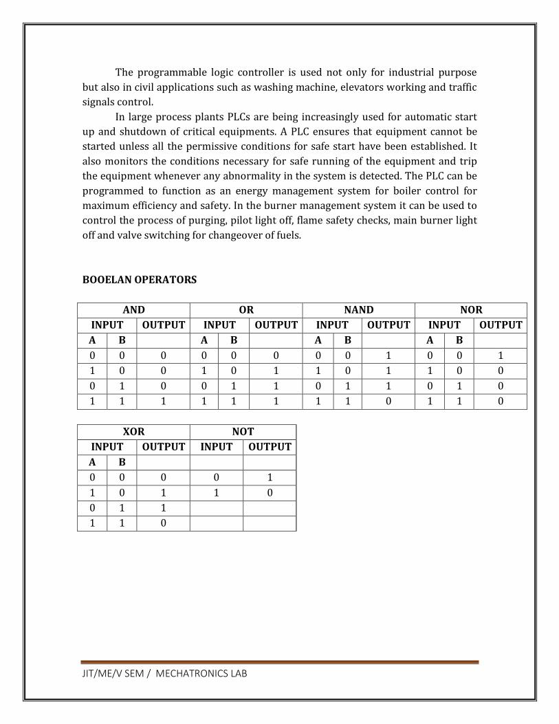
JIT/ME/V SEM / MECHATRONICS LAB
The programmable logic controller is used not only for industrial purpose
but also in civil applications such as washing machine, elevators working and traffic
signals control.
In large process plants PLCs are being increasingly used for automatic start
up and shutdown of critical equipments. A PLC ensures that equipment cannot be
started unless all the permissive conditions for safe start have been established. It
also monitors the conditions necessary for safe running of the equipment and trip
the equipment whenever any abnormality in the system is detected. The PLC can be
programmed to function as an energy management system for boiler control for
maximum efficiency and safety. In the burner management system it can be used to
control the process of purging, pilot light off, flame safety checks, main burner light
off and valve switching for changeover of fuels.
BOOELAN OPERATORS
AND OR NAND NOR
INPUT OUTPUT INPUT OUTPUT INPUT OUTPUT INPUT OUTPUT
A B A B A B A B
0 0 0 0 0 0 0 0 1 0 0 1
1 0 0 1 0 1 1 0 1 1 0 0
0 1 0 0 1 1 0 1 1 0 1 0
1 1 1 1 1 1 1 1 0 1 1 0
XOR NOT
INPUT OUTPUT INPUT OUTPUT
A B
0 0 0 0 1
1 0 1 1 0
0 1 1
1 1 0

JIT/ME/V SEM / MECHATRONICS LAB
Control of Cylinders Using PLC
Objective:
At the end of the lab session, students will have the knowledge how to draw a
circuit diagram and simulate for the cylinders using PLC.
Question 1: Design a circuit diagram and simulate for actuation of single acting
cylinder with on delay timer using PLC
Apparatus required:
Compressor FRL Unit 3/2 Solenoid Operated DCV Single Acting Cylinder PLC Versa Pro Software
Procedure
Draw the circuit diagram Provide +24V and – 24V from PLC trainer to panel Open the versa pro software in desktop Interface PLC with PC using RS232 cable
Write a ladder diagram Output of PLC (Q1) is direct connecting to input o f solenoid coil Following the opening procedure of versa pro software Check the ladder diagram Connect the air supply to FRL unit Run the PLC Sometimes delay the cylinder should be activated

JIT/ME/V SEM / MECHATRONICS LAB
Circuit Diagram
Question 2 : Design a circuit diagram and simulate for actuation of single acting
cylinder with OFF delay timer using PLC
Apparatus Required
Compressor FRL Unit 3/2 Solenoid Operated DCV Single Acting Cylinder PLC
Versa Pro Software
Procedure
Draw the circuit diagram. Provide +24V and –24V from PLC trainer to panel.
Open the versa pro software in desktop. Interface PLC with PC using RS232 cable. Write a ladder diagram. Output of PLC (Q1) is direct connecting to input of solenoid coil.
Following the opening procedure of versa pro software. Check the ladder diagram. Connect the air supply to FRL unit. Run the PLC.
Sometimes delay the cylinder should be activated.

JIT/ME/V SEM / MECHATRONICS LAB
Circuit Diagram
Question 3: Design a circuit diagram and simulate for control of double acting
cylinder with up counter using PLC
Apparatus required
Compressor FRL Unit 5/2 Solenoid Operated DCV Single Acting Cylinder PLC Versa Pro Software
Procedure
Draw the circuit diagram Provide +24V and –24V from PLC trainer to panel Open the versa pro software in desktop
Interface PLC with PC using RS232 cable Write a ladder diagram Output of PLC (Q1) is direct connecting to input of solenoid coil Following the opening procedure of versa pro software Check the ladder diagram Connect the air supply to FRL unit Run the PLC

JIT/ME/V SEM / MECHATRONICS LAB
Circuit Diagram
Question 4: Design a circuit diagram and simulate for control of double acting
cylinder with DOWN counter using PLC
Apparatus required
Compressor FRL Unit 5/2 Solenoid Operated DCV
Single Acting Cylinder PLC Versa Pro Software
Procedure
Draw the circuit diagram Provide +24V and –24V from PLC trainer to panel Open the versa pro software in desktop Interface PLC with PC using RS232 cable Write a ladder diagram
Output of PLC (Q1) is direct connecting to input of solenoid coil Following the opening procedure of versa pro software Check the ladder diagram Connect the air supply to FRL unit
Run the PLC

JIT/ME/V SEM / MECHATRONICS LAB
Circuit Diagram
Question 5: Design a circuit diagram and simulate the single acting cylinder with
AND logic using PLC
Apparatus required:
Compressor FRL Unit 3/2 Solenoid Operated DCV Single Acting Cylinder PLC Versa Pro Software.
Procedure:
Draw the circuit diagram. Provide +24V and –24V from PLC trainer to panel.
Open the versa pro software in desktop. Interface PLC with PC using RS232 cable. Write a ladder diagram. Output of PLC (Q1) is direct connecting to input of solenoid coil. Following the opening procedure of versa pro software. Check the ladder diagram. Connect the air supply to FRL unit. Run the PLC.
When two inputs (1i, 2i) are high, the output is high.

JIT/ME/V SEM / MECHATRONICS LAB
Circuit Diagram
Question 6: Design a circuit diagram and simulate the single acting cylinder with
NOT logic using PLC
APPARATUS REQUIRED:
Compressor FRL Unit 3/2 Solenoid Operated DCV Single Acting Cylinder PLC Versa Pro Software
Procedure:
Draw the circuit diagram. Provide +24V and –24V from PLC trainer to panel. Open the versa pro software in desktop. Interface PLC with PC using RS232 cable. Write a ladder diagram. Output of PLC (Q1) is direct connecting to input of solenoid coil. Following the opening procedure of versa pro software. Check the ladder diagram.
Connect the air supply to FRL unit. Run the PLC.

JIT/ME/V SEM / MECHATRONICS LAB
When two inputs (1i, 2i) are high, the output is high.
Circuit Diagram
Ladder Diagram
Question 7: Design a circuit diagram and simulate the single acting cylinder with
NOR logic using PLC
APPARATUS REQUIRED:
Compressor FRL Unit 3/2 Solenoid Operated DCV Single Acting Cylinder PLC
Versa Pro Software
Procedure:
Draw the circuit diagram. Provide +24V and –24V from PLC trainer to panel. Open the versa pro software in desktop. Interface PLC with PC using RS232 cable.

JIT/ME/V SEM / MECHATRONICS LAB
Write a ladder diagram. Output of PLC (Q1) is direct connecting to input of solenoid coil. Following the opening procedure of versa pro software. Check the ladder diagram.
Connect the air supply to FRL unit. Run the PLC. When two inputs (1i, 2i) are high, the output is high.
Circuit Diagram
Ladder Diagram
Question 5: Design a circuit diagram and simulate the single acting cylinder with
NAND logic using PLC
APPARATUS REQUIRED:
Compressor FRL Unit 3/2 Solenoid Operated DCV Single Acting Cylinder PLC
Versa Pro Software

JIT/ME/V SEM / MECHATRONICS LAB
Procedure:
Draw the circuit diagram. Provide +24V and –24V from PLC trainer to panel. Open the versa pro software in desktop. Interface PLC with PC using RS232 cable. Write a ladder diagram.
Output of PLC (Q1) is direct connecting to input of solenoid coil. Following the opening procedure of versa pro software. Check the ladder diagram. Connect the air supply to FRL unit. Run the PLC.
When two inputs (1i, 2i) are high, the output is high.
Circuit Diagram
Ladder Diagram

JIT/ME/V SEM / MECHATRONICS LAB
REPORT EVALUATION
S.no Description Weightage Mark Awarded
1 Circuit diagram 20
2 Ladder diagram 20
3 Program 20
4 Execution 15
5 Actuation 15
6 Viva-voce 10
Total 100

JIT/ME/V SEM / MECHATRONICS LAB
Ex. No:
Study Of Image Processing Technique
Page No. Date :
Objective:
At the end of the lab session, students will have the information’s on image,
digital image, and the processing techniques.
Image
An image may be defined as a two dimensional function f(x,y), where ‘x’ and ‘y’
are spatial coordinates, and the amplitude of ‘f’ at any pair of coordinates x,y is called
intensity or gray level of the image at that point.
Digital Image
‘x’, ’y’ and the amplitude ‘f’ are all finite and discrete quantities means then
the image is called as digital image.
Digital Image Processing
The field of digital image processing refers to processing of digital images by
a digital computer. Each object has finite number of pixels or pels or image elements
or picture elements.
Image resolution
Image resolution is defined as the number of pixels that can be
accommodated in a unit area. Image resolution depends on number of values for N
and number of bits used in a gray level (m). If N and ‘m’ is high, then the resolution
will be more.
Hue
Hue is an attribute associated with the dominant wavelength in a mixture of light
waves. Thus hue represents dominant color as perceived by an observer eg., red, yellow.
Saturation

JIT/ME/V SEM / MECHATRONICS LAB
It refers to relative purity or the amount of white light mixed with the hue.
The pure spectrum colors are fully saturated (RGB).Color such as pink and lavender
are less saturated. ie., The degree of saturation being inversely proportional to the
amount of white light added. Hue and saturation taken together are called
chromoticity.
Image Histogram
An image histogram is a type of histogram that acts as a graphical
representation of the tonal distribution in a digital image. It plots the number of
pixels for each tonal value.
Horizontal axis tonal variations
Vertical axis represents the number of pixels in that particular tone.
The left side of the horizontal axis represents the black and dark areas, the
middle represents medium grey and the right hand side represents light and pure
white areas. The Vertical axis represents the size of the area that is captured in each
one of these zones.
The histogram for the very dark image will have the majority of its data
points on the left side and centre of the graph.
The histogram for the very bright image with few dark areas is shadows will
have most of its data points on the right side and the centre of the
graphs.
histogram of differential excitation differential excitation scaled to [0,255] 300
200
100
0 -2 -1 0 1 2
Fig 1.1, image histogram
FFT Transform
Typically, 2-D-Fourier transform (2-D-FT) is used as the representation of
complex SAR images. However, the energy of the coefficients of 2-D FT on the
complex SAR image distributes in the whole frequency domain. Generally, the
frequency signals are divided into real and imaginary parts, and quantized with
Lloyd-Max quantizer However, the compression ratios of the frequency domain

JIT/ME/V SEM / MECHATRONICS LAB
compression algorithms are almost limited in 10.4:1o r 9.8:1, which are not very
high. Wavelet transform can locally analyze time and frequency in multiscale and
shows very strong decorrelation ability. As it is particularly suitable for non-
stationary signal processing, wavelet transform has been applied to complex SAR
image compression currently; most compression algorithms of complex SAR image
adopt the traditional wavelet transform.
However, for the complex SAR images, which are rich in edges and texture,
traditional wavelet transform does not show efficient representation. proposed an
algorithm which extracted edges of SAR image with wedge let transform and
encoded the edges and texture separately. used 2-D oriented wavelet transform for
remote sensing compression.
The SAR images used in are not complex SAR images. To the best of our
knowledge, directional wavelet transform has not be applied to the compression of
complex SAR images. Directional wavelet transform achieves the direction
extraction while keeping the property of multiscale analysis of discrete wavelet
transform (DWT). Directional wavelet transform can be divided into two classes:
frequency-domain transform and spatial-domain transform.
The frequency-domain directional wavelet transform, such as contour let
which continuously performs directional filter on the high-frequency sub bands of
wavelet transform, gives an efficient representation of the edges at the cost of high
redundancy. The spatial-domain directional wavelet, such as directional lifting
wavelet transform (DLWT), employs direction prediction for wavelet
decomposition, which adapts the wavelet transform direction to the image edges.
DLWT integrates spatial direction prediction into the wavelet transform lifting
framework, provides an efficient representation of edges along multiple directions
of images, and thus reduces the energy of high-frequency bands and achieves more
energy clustering.
As the real parts and imaginary parts of complex SAR image as well as the
real image of fast FT (FFT) are rich in edges, two complex SAR image coding
schemes using DLWT are proposed. Fourier Transform (FT) with its fast algorithms
(FFT) is an important tool for analysis and processing of many natural signals. FT
has certain limitations to characterise many natural signals, which are non-
stationary (e.g. speech).
Wavelet compression system consists of several components:1) filters and
algorithms for performing wavelet decomposition and reconstruction, 2) a bit
allocation strategy, and 3) quantizers. In order to minimize algorithm complexity
and to reduce susceptibility to channel errors, the quantizer output is not encoded
with an entropy or arithmetic coder. Side information concerning normalization and
bit allocation can be coded in only a few bits for an entire image.

JIT/ME/V SEM / MECHATRONICS LAB
Real image
The wavelet transform is a relatively new technique for decomposition of a
data set with orthogonal (ornonorthogonal) basis functions and is becoming widely
used in image compression. The orthogonal wavelet decomposition provides a multi
resolution representation of a signal over an orthonormal basis. It offers several
advantages for SAR data compression:
1. The decomposition of an image into a representation selective both in
frequency and spatial orientation allows allocation of quantization bits to
"important" components.
2. Algorithms for performing a wavelet decomposition and reconstruction are
recursive, computationally efficient, and easily implemented in hardware.
The computation of a wavelet transform, as described by Mallat, has a
computational burden on the order of &V' . Fast wavelet transform
algorithms can reduce the computational burdentolog -4-
3. The decomposition of an image into a pyramid of detail images results in a
set of coefficients that have reduced dynamic range compared to the original
image. This is particularly important for compression of SAR imagery due to
its very large dynamic range.
4. A wavelet multiscale decomposition of an image is convenient for
progressive image transmission. A coarse resolution image can be selected
from a sensor or database, and then a) browsed at coarse resolution for data
quality, data validation, correct location, etc.and or processed by algorithms
which require only coarse resolution input data, or b) a subset of the image
can be transmitted and displayed at the finest available resolution.
Complex SAR Image
Real part
extracting
1-D IFFT
Spectrum Moving
1-D FFT
JIT/ME/V SEM / MECHATRONICS LAB
Fig 1.2, FFT Program
SAR Image
Synthetic aperture radar (SAR), which is an all-time, all-weather microwave
imaging system, is an important tool for achieving information in the application
field of microwave remote sensing. With synthetic aperture radar (SAR) developing
along the directions of high resolution, multi polarization, multiband, and
multimode, the quantity of SAR image data rises steadily. Data compression
technology is an effective way to alleviate the pressure of transmission and storage
on SAR system.
Complex SAR Image
The complex SAR image, which consists of amplitude and phase, is the first-
level image data of the SAR system. The phase information fidelity in complex SAR
image is crucial to some special applications, such as interferometry and moving
target detection. Therefore, complex SAR image compression requires not only
reasonable amplitude fidelity but also high phase information accuracy, which is
different from the ordinary optical image compression.
Furthermore, compared with optical images, complex SAR images exhibit
significantly higher dynamic range and less spatial correlation. Thus, common
optical image compression algorithms are not suitable for the compression of
complex SAR images. Efficient representation is important to the compression of
complex SAR images.
Reconstructions of the compressed detected imagery were of good to excellent
quality at data rates as low as 0.25 bpp (compression ratio of 32 : 1 when compared
to an uncompressed data rate of 8 bpp). Visual impressions of the imagery were
much better than the SNR’s implied. SNR’s for compressed SAR imagery are lower
than those reported for optical imagery because the high spatial frequency speckle
of SAR imagery does not get accurately reconstructed during the compression
process.
However, accurate reconstruction of speckle is of virtually no importance to
human interpretation of SAR imagery. Complex data rates are expressed as bits per
real or imaginary element (bpe), which corresponds to twice the data rate of
detected data since each pixel consists of two elements. Even when complex data
rates are reported in bits per element, the quality of the reconstructed complex
images is poorer than that of the reconstructed detected images; both shadows and
objects are less well defined in the complex compressed imagery. Reasonable

JIT/ME/V SEM / MECHATRONICS LAB
looking images were obtained at data rates as low as 0.5-1 bpe or 1-2 bpp. On the
other hand, since complex imagery is commonly represented with a two-byte
integer for each real and imaginary part, a compressed data rate of 1 bpp (0.5 bpe)
corresponds to a 32:l compression ratio for complex data.
The first scheme directly encodes real parts and imaginary parts of complex
SAR images using the CCSDS algorithm which replaces DWT by DLWT. The second
scheme first converts a complex image into a real image using FFT, and then
encodes the real image in the CCSDS coding algorithm which also replaces DWT by
DLWT.
Compared with the original CCSDS image coding schemes using DWT, the
proposed two coding schemes show significant performance gain not only in
amplitude peak signal-to-noise ratio (PSNR) but also in mean phase error (MPE).
the best in terms of PSNR and structure similarity (SSIM)]. However, the coding
algorithm based on DLWT achieves better rate-distortion performance than that of
DWT. It is because the rate-distortion performance of coding algorithm is
determined not only by the number of significant coefficients, but also by the
position distribution of significant coefficients, i.e., the clustering capability of
significant coefficients.b the coding bits of significant coefficients with CCSDS
algorithm with K-term nonlinear approximation gets less PSNR and SSIM than DWT,
DLWT coefficients need less actual coding bits for the same number of significant
coefficients than DWT.
Therefore, at the same bit rate, we can encode more coefficients with DLWT
than DWT, and then DLWT may outperform DWT in terms of rate-distortion
performance eventually. DLWT consuming less coding bits is due to the better
clustering capability.
In the first approach the complex image data is converted to a real data format using
a FFT scheme without neglecting any phase information. Shifting the frequency
spectrum by the half bandwidth to positive frequencies, one obtains a negative
spectrum equal to zero. After applying the inverse Fourier transform, the resulting
complex signal can be represented by its real part without loss of any information,
since real and imaginary part of the signal are mutual Hilbert transforms.
The sampling rate are doubled, but because of only using the real part of the
converted signal the data amount is not raised. The particular advantage of this
transformation is, that the wavelet decomposition and compression schemes can be
applied as usual to ordinary intensity data. The reconstructed complex image data is
received by undoing the FIT transformation scheme in reverse order.
In the second approach the complex image data is divided into magnitude and
phase, applying two different compression techniques to both parts. The magnitude
of the complex image data has the same properties as intensity SAR data and can be

compressed, using the discrete wavelet transform and a compression scheme
described below.
The phase of the data is uniformly distributed and highly decorrelated, so
that a nearly lossless compression technique has to be used. In this paper a vector
quantizer was chosen for that. The codebook of the vector quantizer is trained,
using a typical image area of a similar image. In both schemes a block adaptive Max
quantizer was used with a fixed 5 bit quantization, either for the magnitudes of the
image data in our first approach or for the real part of the converted complex image
data in our second approach.
Additionally, a vector quantizer is used on the Max-quantized data, grouping
neighbouring image pixels to specific vectors. The phase of the image data in the
second approach is always quantized by a vector quantizer without utilization of a
block adaptive Max quantizer. The complex SAR data set, we used for both
compression methods, was taken in X-Band by the experimental SAR of DLR during
a mission in 1996 and shows a part of Mount Etna.
For each approach two numerical examples are given with different
compression ratios Both proposed schemes lead to good visual image quality as
where only one compression example of each approach is depicted. The histograms
of the reconstructed image magnitudes are also maintained with respect to their
originals.
The image quality parameters SNR and PSNR as well as the mean phase error
(MPE) and phase standard deviation (PSD) for all the four examples are listed in the
first table with their resulting compression ratio. Additionally, the second approach
is extended to multi polarization mode. The magnitudes of four polarization
channels are separately quantized using a block adaptive Max quantizer with a fixed
5 bit quantization as well. The low-pass component of the final wavelet
decomposition was linearly quantized with maximum quantization.
ME 6712 MECHATRONICS LABORATORY-LAB MODULE 10
View publication stats