jacinto™ 7 soc and pmic functional safety
TRANSCRIPT

Jacinto™ 7 SoC and PMIC functional safety
Mahmut Ciftci, Pauline Wang
Agenda
• Jacinto™ 7 platform overview
• Jacinto 7 SoC safety architecture and hardware diagnostics capabilities
• Jacinto 7 SoC safety software
• PMIC safety mechanisms
• Q&A
2

Jacinto 7 Functional Safety
3
Mahmut Ciftci
Systems Architect,
Jacinto Processors
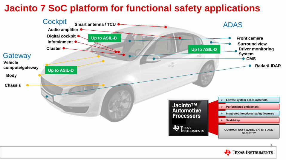
Jacinto 7 SoC platform for functional safety applications
4
Driver monitoring
System
Radar/LIDAR
Surround view
Front camera
Vehicle
compute/gateway
Cluster
Infotainment
Digital cockpit
Audio amplifier
CMS
Smart antenna / TCU
Body
Chassis
Gateway
Cockpit ADAS
Lowest system bill-of-materials
Performance entitlement
Integrated functional safety features
Scalability
COMMON SOFTWARE, SAFETY AND
SECURITY
Up to ASIL-B
Up to ASIL-D
Up to ASIL-D

PCIe SSD
blackbox / data
recording
ADAS system block diagram up to level 3
5
Gateway
processing/
data handling/
actuator control
Deserializer
DS90UB960
Comfort
function
processing
Vision
processing
Sensor Fusion
Processing
Rear
cam
Front
cam
Left
cam
Right
cam
Safety PMIC
TPS6594x
Multi.CAN TRX
TCAN1043
Ethernet
Switch Long
range
radar
Short
range
radar
Short
range
Radar
Ultra sound
sensors
TDA4x
Short
Range
Radar
Short
range
radar
Short
range
radar
Short
range
radar
PCIe
Switch
Trailer
cam
Deep learning
processing
Deserializer
DS90UB960
Driver
monitoring
cam
…
Cam
Even more
deserializer
LIDAR
Inte
gra
ted
or
exte
rna
l
and DRA8xx
Vbat
2 batteries
Vbat
2 Batteries
Protection
LM74800
Wide Vin
LM5141
Wide vin
LM5141
Protection
LM74800
Depending on the safety goal, functions have to be mapped to the QM,
ASIL-B or ASIL-D domain

Optimize entire platform around
programmer productivity on the
MPUs
6
Choose the right core for the right
job
Offload the majority of “work” to
specialized processors. Provide
tools & software to manage
complexity
Heterogeneous compute
capabilities
Image signal
processor C66x
DSP C7x DSP + MMA
Vision
accelerators Display engine
4K
Multi-media
accelerators
Furian8XT
GPU (1-4 cores)
Dual-core
RF5 cluster Dual-core
RF5 cluster
Jacinto™ automotive
processors
64b ARMv8
MPUs
Common high-performance chassis • High-bandwidth coherent SoC interconnect for main processor & memory
• Packet-based interconnect for latency-sensitive interfaces (Ethernet, CSI)
• Dedicated boot engine (early boot)
Memory
system
L3$
Safety • ASIL-B capable SoC
• Safety HW, SW & collateral
• ECC on all memories & buses
Security • Run-time and secure boot
• SoC-level firewalls, BIST
• Dedicated crypto HWAs
Automotive connectivity • CAN-FD, MOST-150, FlexRay, Ethernet AVB
• GbE switch, USB 3.1, PCIe Gen4
ASIL-D
Safety MCU
RTOS
Dual-core
A72 cluster
Dual-core
A72 cluster
Dual-core
A72 cluster
Dual-core
A72 cluster
Mo
re p
roce
ssin
g
pe
rform
an
ce
D e s i g n e d f o r a u t o m o t i v e
s a f e t y a n d r o b u s t n e s s
Jacinto 7 platform: heterogeneous compute
TDA4x / DRA8xx SoCs
AS
IL-D
syste
ma
tic
ca
pa
bili
ty
AS
IL-D
Sa
fety
MC
U
Built
-in
ha
rdw
are
dia
gn
ostics
Cyb
er-
se
cu
rity
Ce
rtific
atio
n s
up
po
rt
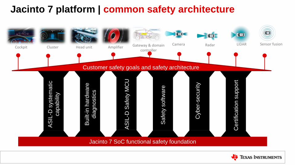
Cockpit Cluster Head unit Amplifier Camera Radar LIDAR Sensor fusion
Jacinto 7 SoC functional safety foundation
Customer safety goals and safety architecture
Sa
fety
so
ftw
are
Gateway & domain controller
Jacinto 7 platform | common safety architecture

8
TI delivers safety analysis
report (FMEDA)
TI HW development process is
TUV SUD certified
Functional safety design packages help
meet functional safety requirements while
managing both systematic and random
failures.
Systematic failures
V&V
Safety plan
Documentation
Config management
Change management
V&V
Personnel competence
Certification
ASIL - A/B/C/D
Functional safety
Safety life cycle
Risk reduction
Process
Diagnostics
Architectural metric
Failure rate
Random failures
CSP = Compliance support package
Development process
TI SW development process is
TUV SUD certified
TI delivers safety manual
documentation
All Jacinto 7 SoCs will be
certified
Jacinto 7 functional safety design for ISO-26262 / IEC-61508
DRA8xx
safety
manual

Jacinto 7 SoC (DRA8xx/TDA4x) functional safety support
Up to ASIL-D / SIL-3
• Integrated Safety MCU
• Independently certified hardware
and software development
processes
• Requirements tracking
• Documentation
• Validation
Up to ASIL-D / SIL-3
• Asymmetric multi-processing
• Lockstep CPUs
• Memory SECDED ECC
• Interconnect protection
• MPU/MMU/firewalls
• Voltage/clock/reset monitors
• Voltage temperature monitors
• Logic/memory BIST
• Built-in tests for diagnostics
…and more.
Functional Safety Design
Package
• Safety manual
• Safety analysis report
• Configurable FMEDA
• Software compliance support
Packages (CSPs)
• 3rd party safety element out of
context (SEooC) assessment
Note: These are platform capabilities. See ‘functional safety’ design package for individual device capabilities.
Systematic capability Built-in diagnostics, low FIT Certification support
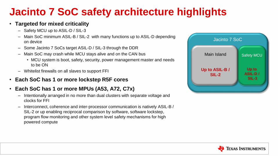
Jacinto 7 SoC safety architecture highlights • Targeted for mixed criticality
– Safety MCU up to ASIL-D / SIL-3
– Main SoC minimum ASIL-B / SIL-2 with many functions up to ASIL-D depending
on device
– Some Jacinto 7 SoCs target ASIL-D / SIL-3 through the DDR
– Main SoC may crash while MCU stays alive and on the CAN bus
• MCU system is boot, safety, security, power management master and needs
to be ON
– Whitelist firewalls on all slaves to support FFI
• Each SoC has 1 or more lockstep R5F cores
• Each SoC has 1 or more MPUs (A53, A72, C7x) – Intentionally arranged in no more than dual clusters with separate voltage and
clocks for FFI
– Interconnect, coherence and inter-processor communication is natively ASIL-B /
SIL-2 or up enabling reciprocal comparison by software, software lockstep,
program flow monitoring and other system level safety mechanisms for high
powered compute
Jacinto 7 SoC
Safety MCU
Up to
ASIL-D /
SIL-3
Main Island
Up to ASIL-B /
SIL-2

Jacinto 7 SoC safety architecture concept
Main SoC
Safety MCU
Wakeup
domain
Lockstep
R5
M3
Arm®/DSP
• “Safety MCU” concept – Region of component is heavily protected by
hardware diagnostic measures • Power • Clock • Reset • CPUs • Memories • Interconnect
– Once the correct operation of a Safety MCU is established, logic in this region can be used to provide diagnostic coverage on other regions
– This partition provides a basis for effective functional safety metrics while providing benefits to minimize overall system BOM overhead cost
• MCU integration concept – Separate voltage supplies
– Separate clocks and resets
– Chip inside a chip
– Main SoC can crash and MCU remains alive, can reboot main SoC

Main SoC
Safety isolation architecture High-power processing • High power processing (Cortex® A/DSP)
• Graphics
• High speed communication (USB/PCIe/etc..)
• Industrial communication
Secure device services • Power control
• Reset control
• Isolation control
• Authentication requests
Safe processing and monitoring • Lockstep R5
• Flash
• Serial communications
• ADCs
Safety MCU
Wakeup
domain
Lockstep
R5
M3
Arm®/DSP
Freedom from interference • Separate voltage
• Separate clocks
• Firewalls
• Internal SPI communication
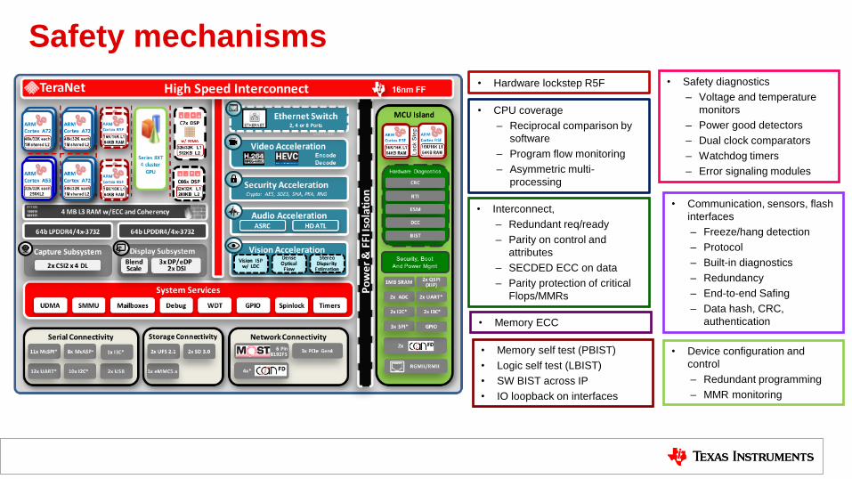
Safety mechanisms
• Hardware lockstep R5F
• CPU coverage
– Reciprocal comparison by
software
– Program flow monitoring
– Asymmetric multi-
processing
• Interconnect,
– Redundant req/ready
– Parity on control and
attributes
– SECDED ECC on data
– Parity protection of critical
Flops/MMRs
• Memory ECC
• Communication, sensors, flash
interfaces
– Freeze/hang detection
– Protocol
– Built-in diagnostics
– Redundancy
– End-to-end Safing
– Data hash, CRC,
authentication
• Safety diagnostics
– Voltage and temperature
monitors
– Power good detectors
– Dual clock comparators
– Watchdog timers
– Error signaling modules
• Device configuration and
control
– Redundant programming
– MMR monitoring
• Memory self test (PBIST)
• Logic self test (LBIST)
• SW BIST across IP
• IO loopback on interfaces
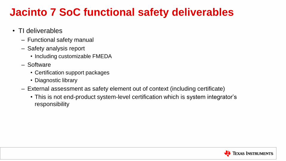
Jacinto 7 SoC functional safety deliverables
• TI deliverables
– Functional safety manual
– Safety analysis report
• Including customizable FMEDA
– Software
• Certification support packages
• Diagnostic library
– External assessment as safety element out of context (including certificate)
• This is not end-product system-level certification which is system integrator’s
responsibility

Jacinto 7 SoC Functional Safety Software
15

Safety MCU
AUTOSAR OS
Vector/
EB /
Nucleus /
Others
Main Subsystem (A72/C7x/C66x/R5F)
TI-RTOS
Low Level Drivers (LLD)
UDMA
Platform Software
Secondary
Bootloader
Board
Library
SW Diagnostics Lib
TI Codegen
Tools with
Compiler
Qualification
Kit
Connectivity (PCIe,..)
Storage
Chip Support Library (CSL-FL)
(Safety path / function)
Vision HWA
Algorithm / Compute Libraries
VXLIB
Middleware components
IPCLib
File system
OSAL
OpenVX
Framework
Security
Framework
Networking
(NDK)
Code
Composer
Studio
ASIL-C/D Safety
Compliant TI Baseline Demo
OpenCL
Tools
OpenCL
Runtime
Tools
Jacinto 7 SDK
TI-DL
Chip Support Library (CSL-FL) DMSC
Firmware
MMALib
Customer
choice/
engagement
NOT a TI
Deliverable
Radar Lib
MCU Subsystem
(R5F/M3)
AUTOSAR
MCAL
ASIL-B Safety
Compliant Legend
Ethernet, Eth Switch Capture (CSI2) & Display
Auto valet parking / Gateway / Cockpit example application
Task
Scheduler,
Interrupts,
Semaphores,
Timers
C7x Hwi,
C66 Hwi,
C7x Supv,
Cache,
Exception,
TimeStamp
Driver Model,
Rest of
OS/Package
R5F/C7x/C66x

Functional safety software components
17
ASIL-C/D
• AUTOSAR MCAL on Safety Island
(CAN, DIO, SPI, ETH, IPC, ADC,
PWM, WDG, GPT)
• CSL-FLs for Safety IPs (ECC,
CRC, DCC, ESM, BIST, VTM,
PGD, POK, ADC)
• SCI Client, UDMA, Resource
Manager
• DMSC Firmware
• TI-RTOS
ASIL-B
• CSL-FLs for all IPs in safety path
• MMA, TIDL Library
• LLDs for CSI2, DSS, VHWA, IPC
• Compiler Qual Kit
• AUTOSAR
Software Diagnostic Library (SDL)
LBIST / PBIST
• Power on self test on MCU R5F, M3
• SW controlled on R5F, A72, C7x
• SW controlled PBIST of MSMC
RAM
Loopback: CAN, SPI, ...
• Functionality check: CRC, ECC, ...
• Monitors: RTI, DCC, ESM, Frame
freeze detect, …
• Error Injection
Software Test Library(STL)
• C66x, MMA, C7x: TBD
• A72, R5F: ARM STL release
Functional Software Diagnostics
• Reference SW for Safety IP usage
• Reference SW for safety manual
items allocated to SW
• Example code for FFI, Main / MCU
island isolation and other safety
features
Reference Software

Software certification support package
Compliance Support Package (CSP):
• Software safety manual
• TI internal audit report
• Requirements, test plan and reports
• Traceability data
• Dynamic code coverage analysis
• Static code analysis/MISRA-C
• Safety diagnostics library and manual
• Compiler qualification kit
• Software FMEA report

Jacinto 7 PMIC functional safety
19
Pauline Wang
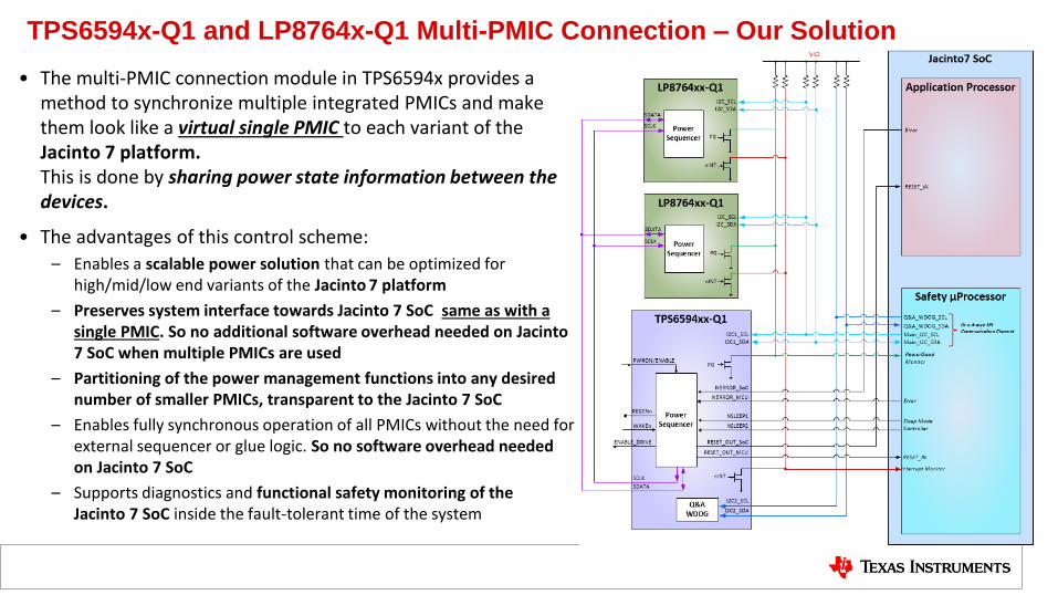
TPS6594x-Q1 and LP8764x-Q1 Multi-PMIC Connection – Our Solution
• The multi-PMIC connection module in TPS6594x provides a method to synchronize multiple integrated PMICs and make them look like a virtual single PMIC to each variant of the Jacinto 7 platform. This is done by sharing power state information between the devices.
• The advantages of this control scheme:
– Enables a scalable power solution that can be optimized for high/mid/low end variants of the Jacinto 7 platform
– Preserves system interface towards Jacinto 7 SoC same as with a single PMIC. So no additional software overhead needed on Jacinto 7 SoC when multiple PMICs are used
– Partitioning of the power management functions into any desired number of smaller PMICs, transparent to the Jacinto 7 SoC
– Enables fully synchronous operation of all PMICs without the need for external sequencer or glue logic. So no software overhead needed on Jacinto 7 SoC
– Supports diagnostics and functional safety monitoring of the Jacinto 7 SoC inside the fault-tolerant time of the system
20

TPS6594-Q1 and LP8764-Q1 Functional Safety Capability Supporting tools and
documents
FMEDA
Safety Manual
Functional Safety
Analysis Report:
DFMEA
pin-FMEA
FTA & DFA
Technical Reference Manual(s)
for powering Jacinto 7 SoC with
TPS6594x / LP8764x PMICs
SDK for Jacinto 7 SoCs
Systematic
Developed according
SafeTI™ Development
Process with TÜV SÜD
certification for ISO26262
ASIL-D target
Hardware Metrics
> 99% Single-Point Metric and
>90% Latent-Fault Metrics
Accurate and fast Output
Voltage Monitoring
Accurate and fast Input Voltage
Monitoring
Fast Over-Voltage Protection
Q&A Watchdog
Error Signal Monitors
CRC on Communication
Interfaces and SPMI bus
CRC on Configuration Registers
CRC on internal memory
Built-In Self-Tests on Voltage
Monitors, State Machine, SPMI
Bus, Watchdog and Error Signal
Monitors

Safety Concept for supplying Processor Fail-Silent Safety Concept As long as SoC and Safety MCU in Jacinto 7 SoC work properly:
• SoC checks sensor data
• Safety MCU: • Checks the SoC operation
• Controls the actuators
• Checks whether the actuators react on the
control in the expected way
TPS6594xx
Power Supply Safety Functions
LP8764x
Power Supply Outputs
Power Supply Outputs
TI Application Processor
DCDC5LDO4
Safety-Island MCU
VSUPPLY
VMON
PRE_REG HV
Load Switch
Q&A Watchdog
MCU Error Signal
Monitor
I2C 2MCU
CORE
MC
U
CO
RE
MCU Reset
SoC Reset
nRESET
SoC
nRESET
I2C 1
nINT
DCDC4
DCDC3
DCDC2
DCDC1
LDO3
LDO2
LDO1
DCDC4
DCDC3
DCDC2
DCDC1
Switch Control
SPMI
SPMI
Temp. Prewarning +Shutdown
Current Limit
ABIST
CLKMON
LBIST
EC / CRC Register Map
Comm. CRC
SoC Error Signal Monitor
GPIO read-back
ENDRV
Comm. CRC
Comm. CRC
ABIST
CLKMON
LBIST
GPIO read-back
I2C Comm.
CRC
nINT
Comm. CRC
Power Supply Safety Functions
VMON
Temp. Prewarning +Shutdown
Current Limit
I2C 2
I2C 1
nINT
Interfaces to remote
Actuators ( e.g. CAN)
Enable
Interfaces to remote Sensors
(e.g. FPD / CAR-ETH /CAN)
Jacinto 7 SoC

Safety Concept for supplying Processor Fail-Silent Safety Concept As long as SoC and Safety MCU in Jacinto 7 SoC work properly:
• SoC checks sensor data
• Safety MCU: • Checks the SoC operation
• Controls the actuators
• Checks whether the actuators react on the
control in the expected way
For failures which would cause improper
operation of the Safety MCU or SoC:
I. PMIC puts system in safe state through
EN_DRV pin
TPS6594xx
Power Supply Safety Functions
LP8764x
Power Supply Outputs
Power Supply Outputs
TI Application Processor
DCDC5LDO4
Safety-Island MCU
VSUPPLY
VMON
PRE_REG HV
Load Switch
Q&A Watchdog
MCU Error Signal
Monitor
I2C 2MCU
CORE
MC
U
CO
RE
MCU Reset
SoC Reset
nRESET
SoC
nRESET
I2C 1
nINT
DCDC4
DCDC3
DCDC2
DCDC1
LDO3
LDO2
LDO1
DCDC4
DCDC3
DCDC2
DCDC1
Switch Control
SPMI
SPMI
Temp. Prewarning +Shutdown
Current Limit
ABIST
CLKMON
LBIST
EC / CRC Register Map
Comm. CRC
SoC Error Signal Monitor
GPIO read-back
ENDRV
Comm. CRC
Comm. CRC
ABIST
CLKMON
LBIST
GPIO read-back
I2C Comm.
CRC
nINT
Comm. CRC
Power Supply Safety Functions
VMON
Temp. Prewarning +Shutdown
Current Limit
I2C 2
I2C 1
nINT
Interfaces to remote
Actuators ( e.g. CAN)
Enable
Interfaces to remote Sensors
(e.g. FPD / CAR-ETH /CAN)
Jacinto 7 SoC
I)

Safety Concept for supplying Processor Fail-Silent Safety Concept As long as SoC and Safety MCU in Jacinto 7 SoC work properly:
• SoC checks sensor data
• Safety MCU: • Checks the SoC operation
• Controls the actuators
• Checks whether the actuators react on the
control in the expected way
For failures which would cause improper
operation of the Safety MCU or SoC:
I. PMIC puts system in safe state through
EN_DRV pin
II. PMIC resets SoC and/or Safety MCU if
necessary
TPS6594xx
Power Supply Safety Functions
LP8764x
Power Supply Outputs
Power Supply Outputs
TI Application Processor
DCDC5LDO4
Safety-Island MCU
VSUPPLY
VMON
PRE_REG HV
Load Switch
Q&A Watchdog
MCU Error Signal
Monitor
I2C 2MCU
CORE
MC
U
CO
RE
MCU Reset
SoC Reset
nRESET
SoC
nRESET
I2C 1
nINT
DCDC4
DCDC3
DCDC2
DCDC1
LDO3
LDO2
LDO1
DCDC4
DCDC3
DCDC2
DCDC1
Switch Control
SPMI
SPMI
Temp. Prewarning +Shutdown
Current Limit
ABIST
CLKMON
LBIST
EC / CRC Register Map
Comm. CRC
SoC Error Signal Monitor
GPIO read-back
ENDRV
Comm. CRC
Comm. CRC
ABIST
CLKMON
LBIST
GPIO read-back
I2C Comm.
CRC
nINT
Comm. CRC
Power Supply Safety Functions
VMON
Temp. Prewarning +Shutdown
Current Limit
I2C 2
I2C 1
nINT
Interfaces to remote
Actuators ( e.g. CAN)
Enable
Interfaces to remote Sensors
(e.g. FPD / CAR-ETH /CAN)
Jacinto 7 SoC
I)
II)
II)

Safety Concept for supplying Processor Fail-Silent Safety Concept As long as SoC and Safety MCU in Jacinto 7 SoC work properly:
• SoC checks sensor data
• Safety MCU: • Checks the SoC operation
• Controls the actuators
• Checks whether the actuators react on the
control in the expected way
For failures which would cause improper
operation of the Safety MCU or SoC:
I. PMIC puts system in safe state through
EN_DRV pin
II. PMIC resets SoC and/or Safety MCU if
necessary
III. PMIC reports all previously occurred errors during a drive-cycle to Jacinto 7 SoC
TPS6594xx
Power Supply Safety Functions
LP8764x
Power Supply Outputs
Power Supply Outputs
TI Application Processor
DCDC5LDO4
Safety-Island MCU
VSUPPLY
VMON
PRE_REG HV
Load Switch
Q&A Watchdog
MCU Error Signal
Monitor
I2C 2MCU
CORE
MC
U
CO
RE
MCU Reset
SoC Reset
nRESET
SoC
nRESET
I2C 1
nINT
DCDC4
DCDC3
DCDC2
DCDC1
LDO3
LDO2
LDO1
DCDC4
DCDC3
DCDC2
DCDC1
Switch Control
SPMI
SPMI
Temp. Prewarning +Shutdown
Current Limit
ABIST
CLKMON
LBIST
EC / CRC Register Map
Comm. CRC
SoC Error Signal Monitor
GPIO read-back
ENDRV
Comm. CRC
Comm. CRC
ABIST
CLKMON
LBIST
GPIO read-back
I2C Comm.
CRC
nINT
Comm. CRC
Power Supply Safety Functions
VMON
Temp. Prewarning +Shutdown
Current Limit
I2C 2
I2C 1
nINT
Interfaces to remote
Actuators ( e.g. CAN)
Enable
Interfaces to remote Sensors
(e.g. FPD / CAR-ETH /CAN)
Jacinto 7 SoC
I)
III)
II)
II)
TPS6594xx
Power Supply Safety Functions
LP8764x
Power Supply Outputs
Power Supply Outputs
TI Application Processor
DCDC5LDO4
Safety-Island MCU
VSUPPLY
VMON
PRE_REG HV
Load Switch
Q&A Watchdog
MCU Error Signal
Monitor
I2C 2MCU
CORE
MC
U
CO
RE
MCU Reset
SoC Reset
nRESET
SoC
nRESET
I2C 1
nINT
DCDC4
DCDC3
DCDC2
DCDC1
LDO3
LDO2
LDO1
DCDC4
DCDC3
DCDC2
DCDC1
Switch Control
SPMI
SPMI
Temp. Prewarning +Shutdown
Current Limit
ABIST
CLKMON
LBIST
EC / CRC Register Map
Comm. CRC
SoC Error Signal Monitor
GPIO read-back
ENDRV
Comm. CRC
Comm. CRC
ABIST
CLKMON
LBIST
GPIO read-back
I2C Comm.
CRC
nINT
Comm. CRC
Power Supply Safety Functions
VMON
Temp. Prewarning +Shutdown
Current Limit
I2C 2
I2C 1
nINT
Interfaces to remote
Actuators ( e.g. CAN)
Enable
Interfaces to remote Sensors
(e.g. FPD / CAR-ETH /CAN)
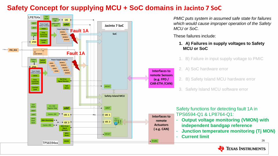
Safety Concept for supplying MCU + SoC domains in Jacinto 7 SoC
26
PMIC puts system in assumed safe state for failures
which would cause improper operation of the Safety
MCU or SoC.
These failures include:
1. A) Failures in supply voltages to Safety
MCU or SoC
1. B) Failure in input supply voltage to PMIC
2. A) SoC hardware error
2. B) Safety Island MCU hardware error
3. Safety Island MCU software error
Safety functions for detecting fault 1A in
TPS6594-Q1 & LP8764-Q1:
- Output voltage monitoring (VMON) with
independent bandgap reference
- Junction temperature monitoring (Tj MON)
- Current limit
Fault 1A
Fault 1A
Jacinto 7 SoC

TPS6594xx
Power Supply Safety Functions
LP8764x
Power Supply Outputs
Power Supply Outputs
TI Application Processor
DCDC5LDO4
Safety-Island MCU
VSUPPLY
VMON
PRE_REG HV
Load Switch
Q&A Watchdog
MCU Error Signal
Monitor
I2C 2MCU
CORE
MC
U
CO
RE
MCU Reset
SoC Reset
nRESET
SoC
nRESET
I2C 1
nINT
DCDC4
DCDC3
DCDC2
DCDC1
LDO3
LDO2
LDO1
DCDC4
DCDC3
DCDC2
DCDC1
Switch Control
SPMI
SPMI
Temp. Prewarning +Shutdown
Current Limit
ABIST
CLKMON
LBIST
EC / CRC Register Map
Comm. CRC
SoC Error Signal Monitor
GPIO read-back
ENDRV
Comm. CRC
Comm. CRC
ABIST
CLKMON
LBIST
GPIO read-back
I2C Comm.
CRC
nINT
Comm. CRC
Power Supply Safety Functions
VMON
Temp. Prewarning +Shutdown
Current Limit
I2C 2
I2C 1
nINT
Interfaces to remote
Actuators ( e.g. CAN)
Enable
Interfaces to remote Sensors
(e.g. FPD / CAR-ETH /CAN)
Safety Concept for supplying MCU + SoC domains in Jacinto 7 SoC
27
PMIC puts system in assumed safe state for failures
which would cause improper operation of the Safety
MCU or SoC.
These failures include:
1. A) Failures in supply voltages to Safety
MCU or SoC
1. B) Failure in input supply voltage to PMIC
2. A) SoC hardware error
2. B) Safety Island MCU hardware error
3. Safety Island MCU software error
Safety Functions for detecting Fault 1A in
TPS6594-Q1 & LP8764-Q1:
- Output Voltage Monitoring (VMON) with
independent bandgap reference
- Junction Temperature Monitoring (Tj MON)
- Current Limit
Fault 1A.1
Jacinto 7 SoC
Tailorable handling of output voltage faults:
1. Fault in MCU supply domain:
I. PMIC pulls ENDRV low
II. PMIC puts MCU and SoC in reset and shuts down all power-
supply rails
III. PMIC reports the error to the MCU on re-start (nINT pin low +
error flag)
2. SoC supply domain:
I. PMIC puts SoC in reset. MCU not put in reset
II. PMIC shuts down the power-supply rails mapped to the SoC.
PMIC keeps MCU supply rails on. ENDRV can stay high
III. PMIC reports the error to the MCU (nINT pin low + error flag)
3. OTHER supply domain:
I. PMIC reports the error to the MCU. PMIC keeps all rails on, and
no reset to MCU and SoC (nINT pin low + error flag)

TPS6594xx
Power Supply Safety Functions
LP8764x
Power Supply Outputs
Power Supply Outputs
TI Application Processor
DCDC5LDO4
Safety-Island MCU
VSUPPLY
VMON
PRE_REG HV
Load Switch
Q&A Watchdog
MCU Error Signal
Monitor
I2C 2MCU
CORE
MC
U
CO
RE
MCU Reset
SoC Reset
nRESET
SoC
nRESET
I2C 1
nINT
DCDC4
DCDC3
DCDC2
DCDC1
LDO3
LDO2
LDO1
DCDC4
DCDC3
DCDC2
DCDC1
Switch Control
SPMI
SPMI
Temp. Prewarning +Shutdown
Current Limit
ABIST
CLKMON
LBIST
EC / CRC Register Map
Comm. CRC
SoC Error Signal Monitor
GPIO read-back
ENDRV
Comm. CRC
Comm. CRC
ABIST
CLKMON
LBIST
GPIO read-back
I2C Comm.
CRC
nINT
Comm. CRC
Power Supply Safety Functions
VMON
Temp. Prewarning +Shutdown
Current Limit
I2C 2
I2C 1
nINT
Interfaces to remote
Actuators ( e.g. CAN)
Enable
Interfaces to remote Sensors
(e.g. FPD / CAR-ETH /CAN)
Safety Concept for supplying MCU + SoC domains in Jacinto 7 SoC
28
PMIC puts system in assumed safe state for failures
which would cause improper operation of the Safety
MCU or SoC.
These failures include:
1. A) Failures in supply voltages to Safety
MCU or SoC
1. B) Failure in input supply voltage to PMIC
2. A) SoC hardware error
2. B) Safety Island MCU hardware error
3. Safety Island MCU software error
Safety Functions for detecting Fault 1A in
TPS6594-Q1 & LP8764-Q1:
- Output Voltage Monitoring (VMON) with
independent bandgap reference
- Junction Temperature Monitoring (Tj MON)
- Current Limit
Fault 1A.2 Jacinto 7 SoC
Tailorable handling of output voltage faults:
1. Fault in MCU supply domain:
I. PMIC pulls ENDRV low
II. PMIC puts MCU and SoC in reset and shuts down all power-
supply rails
III. PMIC reports the error to the MCU on re-start (nINT pin low +
error flag)
2. SoC supply domain:
I. PMIC puts SoC in reset. MCU not put in reset
II. PMIC shuts down the power-supply rails mapped to the SoC.
PMIC keeps MCU supply rails on. ENDRV can stay high
III. PMIC reports the error to the MCU (nINT pin low + error flag)
3. OTHER supply domain:
I. PMIC reports the error to the MCU. PMIC keeps all rails on, and
no reset to MCU and SoC (nINT pin low + error flag)

TPS6594xx
Power Supply Safety Functions
LP8764x
Power Supply Outputs
Power Supply Outputs
TI Application Processor
DCDC5LDO4
Safety-Island MCU
VSUPPLY
VMON
PRE_REG HV
Load Switch
Q&A Watchdog
MCU Error Signal
Monitor
I2C 2MCU
CORE
MC
U
CO
RE
MCU Reset
SoC Reset
nRESET
SoC
nRESET
I2C 1
nINT
DCDC4
DCDC3
DCDC2
DCDC1
LDO3
LDO2
LDO1
DCDC4
DCDC3
DCDC2
DCDC1
Switch Control
SPMI
SPMI
Temp. Prewarning +Shutdown
Current Limit
ABIST
CLKMON
LBIST
EC / CRC Register Map
Comm. CRC
SoC Error Signal Monitor
GPIO read-back
ENDRV
Comm. CRC
Comm. CRC
ABIST
CLKMON
LBIST
GPIO read-back
I2C Comm.
CRC
nINT
Comm. CRC
Power Supply Safety Functions
VMON
Temp. Prewarning +Shutdown
Current Limit
I2C 2
I2C 1
nINT
Interfaces to remote
Actuators ( e.g. CAN)
Enable
Interfaces to remote Sensors
(e.g. FPD / CAR-ETH /CAN)
Safety Concept for supplying MCU + SoC domains in JacintoTM 7
29
PMIC puts system in assumed safe state for failures
which would cause improper operation of the Safety
MCU or SoC.
These failures include:
1. A) Failures in supply voltages to Safety
MCU or SoC
1. B) Failure in input supply voltage to PMIC
2. A) SoC hardware error
2. B) Safety Island MCU hardware error
3. Safety Island MCU software error
Safety Functions for detecting Fault 1A in
TPS6594-Q1 & LP8764-Q1:
- Output Voltage Monitoring (VMON) with
independent bandgap reference
- Junction Temperature Monitoring (Tj MON)
- Current Limit
Fault 1A.3
Jacinto 7 SoC
Tailorable handling of output voltage faults:
1. Fault in MCU supply domain:
I. PMIC pulls ENDRV low
II. PMIC puts MCU and SoC in reset and shuts down all power-
supply rails
III. PMIC reports the error to the MCU on re-start (nINT pin low +
error flag)
2. SoC supply domain:
I. PMIC puts SoC in reset. MCU not put in reset
II. PMIC shuts down the power-supply rails mapped to the SoC.
PMIC keeps MCU supply rails on. ENDRV can stay high
III. PMIC reports the error to the MCU (nINT pin low + error flag)
3. OTHER supply domain:
I. PMIC reports the error to the MCU. PMIC keeps all rails on, and
no reset to MCU and SoC (nINT pin low + error flag)

Interfaces to remote
Actuators ( e.g. CAN)
TPS6594xx
Power Supply Safety
Functions
Power Supply Outputs
TI Application Processor
DCDC5LDO4
Safety-Island MCU
VSUPPLY
VMON
PRE_REG HV Load Switch
Q&A Watchdog
MCU Error Signal Monitor
I2C 2
MCU
CORE
MC
U
CO
RE
MCU Reset
SoC Reset
nRESET
SoC
nRESET
I2C 1
nINT
DCDC4
DCDC3
DCDC2
DCDC1
LDO3
LDO2
LDO1
Switch Control
Tj Mon
Current Limit
SoC Error Signal Monitor
ENDRV Enable
CRC
I2C 2
I2C 1
Interrupt
CRC
Interfaces to remote
Sensors (e.g. FPD /
CAR-ETH /CAN)
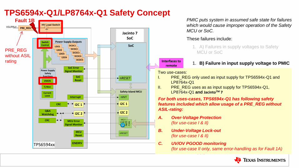
TPS6594x-Q1/LP8764x-Q1 Safety Concept
30
Fault 1B
Safety functions for detecting fault 1B:
- Input voltage monitoring (VMON) =>
independent /isolated function inside PMIC
- Switch control
- External FET (HV load switch)
Note: LP8764 does not have the switch control.
Use supply line behind external FET to supply
the LP8764
PMIC puts system in assumed safe state for failures
which would cause improper operation of the Safety
MCU or SoC.
These failures include:
1. A) Failures in supply voltages to Safety
MCU or SoC
1. B) Failure in input supply voltage to PMIC
2. A) SoC hardware error
2. B) Safety MCU hardware error
3. Safety MCU software error
PRE_REG
without ASIL
rating
Jacinto 7 SoC
Interfaces to remote
Actuators ( e.g. CAN)
TPS6594xx
Power Supply Safety
Functions
Power Supply Outputs
TI Application Processor
DCDC5LDO4
Safety-Island MCU
VSUPPLY
VMON
PRE_REG HV Load Switch
Q&A Watchdog
MCU Error Signal Monitor
I2C 2
MCU
CORE
MC
U
CO
RE
MCU Reset
SoC Reset
nRESET
SoC
nRESET
I2C 1
nINT
DCDC4
DCDC3
DCDC2
DCDC1
LDO3
LDO2
LDO1
Switch Control
Tj Mon
Current Limit
SoC Error Signal Monitor
ENDRV Enable
CRC
I2C 2
I2C 1
Interrupt
CRC
Interfaces to remote
Sensors (e.g. FPD /
CAR-ETH /CAN)
TPS6594x-Q1/LP8764x-Q1 Safety Concept
31
Fault 1B
Safety Functions for detecting Fault 1B:
- Input Voltage Monitoring (VMON) =>
independent /isolated function inside PMIC
- Switch Control
- External FET (HV Load Switch)
Note: LP8764 does not have the Switch
Control. Use supply line behind External FET to
supply the LP8764
PMIC puts system in assumed safe state for failures
which would cause improper operation of the Safety
MCU or SoC.
These failures include:
1. A) Failures in supply voltages to Safety
MCU or SoC
1. B) Failure in input supply voltage to PMIC
2. A) SoC hardware error
2. B) Safety Island MCU hardware error
3. Safety Island MCU software error
PRE_REG
without ASIL
rating
Jacinto 7 SoC
Two use-cases:
I. PRE_REG only used as input supply for TPS6594x-Q1 and
LP8764x-Q1
II. PRE_REG uses as as input supply for TPS6594x-Q1,
LP8764x-Q1 and JacintoTM 7
For both uses-cases, TPS6594x-Q1 has following safety
features included which allow usage of a PRE_REG without
ASIL-rating:
A. Over-Voltage Protection
(for use-case I & II)
B. Under-Voltage Lock-out
(for use-case I & II)
C. UV/OV PGOOD monitoring
(for use-case II only, same error-handling as for Fault 1A)

Interfaces to remote
Actuators ( e.g. CAN)
TPS6594xx
Power Supply Safety
Functions
Power Supply Outputs
TI Application Processor
DCDC5LDO4
Safety-Island MCU
VSUPPLY
VMON
PRE_REG HV Load Switch
Q&A Watchdog
MCU Error Signal Monitor
I2C 2
MCU
CORE
MC
U
CO
RE
MCU Reset
SoC Reset
nRESET
SoC
nRESET
I2C 1
nINT
DCDC4
DCDC3
DCDC2
DCDC1
LDO3
LDO2
LDO1
Switch Control
Tj Mon
Current Limit
SoC Error Signal Monitor
ENDRV Enable
CRC
I2C 2
I2C 1
Interrupt
CRC
Interfaces to remote
Sensors (e.g. FPD /
CAR-ETH /CAN)
TPS6594x-Q1/LP8764x-Q1 Safety Concept
32
Fault 1B
Safety Functions for detecting Fault 1B:
- Input Voltage Monitoring (VMON) =>
independent /isolated function inside PMIC
- Switch Control
- External FET (HV Load Switch)
Note: LP8764 does not have the Switch
Control. Use supply line behind External FET to
supply the LP8764
PMIC puts system in assumed safe state for failures
which would cause improper operation of the Safety
MCU or SoC.
These failures include:
1. A) Failures in supply voltages to Safety
MCU or SoC
1. B) Failure in input supply voltage to PMIC
2. A) SoC hardware error
2. B) Safety Island MCU hardware error
3. Safety Island MCU software error
PRE_REG
without ASIL
rating
Jacinto 7 SoC
Objective of TPS6594x-Q1 input over-voltage
protection:
KEEP VCCA voltage < EOS voltage level of
TPS6594x-Q1 to allow TPS6594x-Q1 keeping
system in safe state
How?
In case of PRE_REG overvoltage, TPS6594x-
Q1 opens external FET fast enough
Complete system will reach a powered-
down state, which is a safe state from
Functional Safety point-of-view
Interfaces to remote
Actuators ( e.g. CAN)
TPS6594xx
Power Supply Safety
Functions
Power Supply Outputs
TI Application Processor
DCDC5LDO4
Safety-Island MCU
VSUPPLY
VMON
PRE_REG HV Load Switch
Q&A Watchdog
MCU Error Signal Monitor
I2C 2
MCU
CORE
MC
U
CO
RE
MCU Reset
SoC Reset
nRESET
SoC
nRESET
I2C 1
nINT
DCDC4
DCDC3
DCDC2
DCDC1
LDO3
LDO2
LDO1
Switch Control
Tj Mon
Current Limit
SoC Error Signal Monitor
ENDRV Enable
CRC
I2C 2
I2C 1
Interrupt
CRC
Interfaces to remote
Sensors (e.g. FPD /
CAR-ETH /CAN)
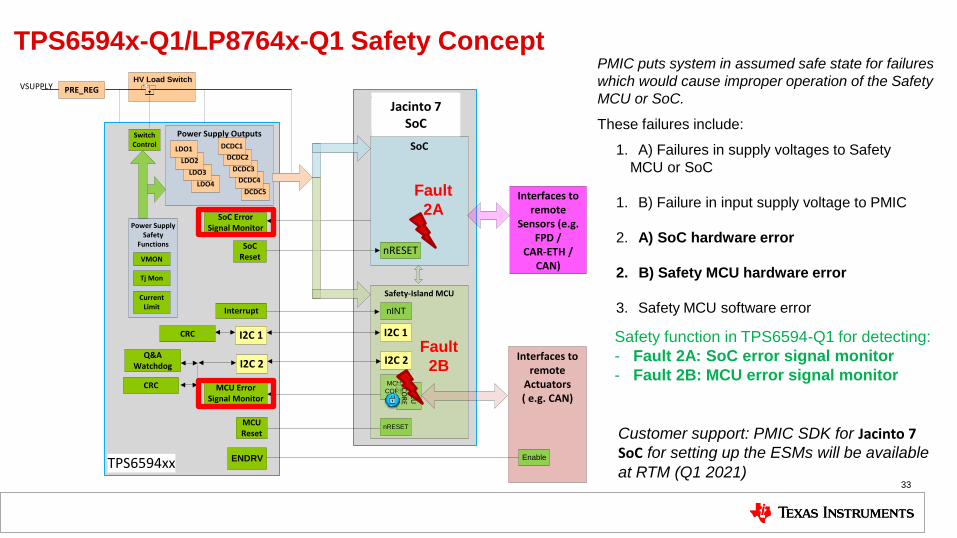
TPS6594x-Q1/LP8764x-Q1 Safety Concept
33
Fault
2A
Safety function in TPS6594-Q1 for detecting:
- Fault 2A: SoC error signal monitor
- Fault 2B: MCU error signal monitor
PMIC puts system in assumed safe state for failures
which would cause improper operation of the Safety
MCU or SoC.
These failures include:
1. A) Failures in supply voltages to Safety
MCU or SoC
1. B) Failure in input supply voltage to PMIC
2. A) SoC hardware error
2. B) Safety MCU hardware error
3. Safety MCU software error
Customer support: PMIC SDK for Jacinto 7 SoC for setting up the ESMs will be available
at RTM (Q1 2021)
Fault
2B
Jacinto 7 SoC

Interfaces to remote
Actuators ( e.g. CAN)
TPS6594xx
Power Supply Safety
Functions
Power Supply Outputs
TI Application Processor
DCDC5LDO4
Safety-Island MCU
VSUPPLY
VMON
PRE_REG HV Load Switch
Q&A Watchdog
MCU Error Signal Monitor
I2C 2
MCU
CORE
MC
U
CO
RE
MCU Reset
SoC Reset
nRESET
SoC
nRESET
I2C 1
nINT
DCDC4
DCDC3
DCDC2
DCDC1
LDO3
LDO2
LDO1
Switch Control
Tj Mon
Current Limit
SoC Error Signal Monitor
ENDRV Enable
CRC
I2C 2
I2C 1
Interrupt
CRC
Interfaces to remote
Sensors (e.g. FPD /
CAR-ETH /CAN)
TPS6594x-Q1/LP8764x-Q1 Safety Concept
34
Fault
3
Safety function in TPS6594-Q1 for detecting
fault 3:
- Q&A watchdog
PMIC puts system in assumed safe state for failures
which would cause improper operation of the Safety
MCU or SoC.
These failures include:
1. A) Failures in supply voltages to Safety
MCU or SoC
1. B) Failure in input supply voltage to PMIC
2. A) SoC hardware error
2. B) Safety MCU hardware error
3. Safety MCU software error
Jacinto 7 SoC
Customer support: PMIC SDK for Jacinto 7 SoC for setting up the watchdog will be
available at RTM (Q1 2021)

Safety Concept for supplying Processor Safety mechanisms inside each PMIC for
internal faults :
- Clock monitor
- Internal bias voltage monitor
Safety mechanisms inside each PMIC for
latent-faults:
- ABIST (for VMON and temp monitor)
- LBIST (for watchdog, error signal monitors,
Error handling logic, I2C interfaces, clock
monitor)
- CRC on volatile and non-volatile memory
- Read-back on EN_DRV, nRSTOUT,
nRSTOUT_SoC, nINT
- Watchdog + CRC on PMIC interconnect bus
- CRC on I2C interfaces
- Fail-short test on VSYS-OVP FET
TPS6594xx
Power Supply Safety Functions
LP8764x
Power Supply Outputs
Power Supply Outputs
TI Application Processor
DCDC5LDO4
Safety-Island MCU
VSUPPLY
VMON
PRE_REG HV
Load Switch
Q&A Watchdog
MCU Error Signal
Monitor
I2C 2MCU
CORE
MC
U
CO
RE
MCU Reset
SoC Reset
nRESET
SoC
nRESET
I2C 1
nINT
DCDC4
DCDC3
DCDC2
DCDC1
LDO3
LDO2
LDO1
DCDC4
DCDC3
DCDC2
DCDC1
Switch Control
SPMI
SPMI
Temp. Prewarning +Shutdown
Current Limit
ABIST
CLKMON
LBIST
EC / CRC Register Map
Comm. CRC
SoC Error Signal Monitor
GPIO read-back
ENDRV
Comm. CRC
Comm. CRC
ABIST
CLKMON
LBIST
GPIO read-back
I2C Comm.
CRC
nINT
Comm. CRC
Power Supply Safety Functions
VMON
Temp. Prewarning +Shutdown
Current Limit
I2C 2
I2C 1
nINT
Interfaces to remote
Actuators ( e.g. CAN)
Enable
Interfaces to remote Sensors
(e.g. FPD / CAR-ETH /CAN)
Jacinto 7 SoC
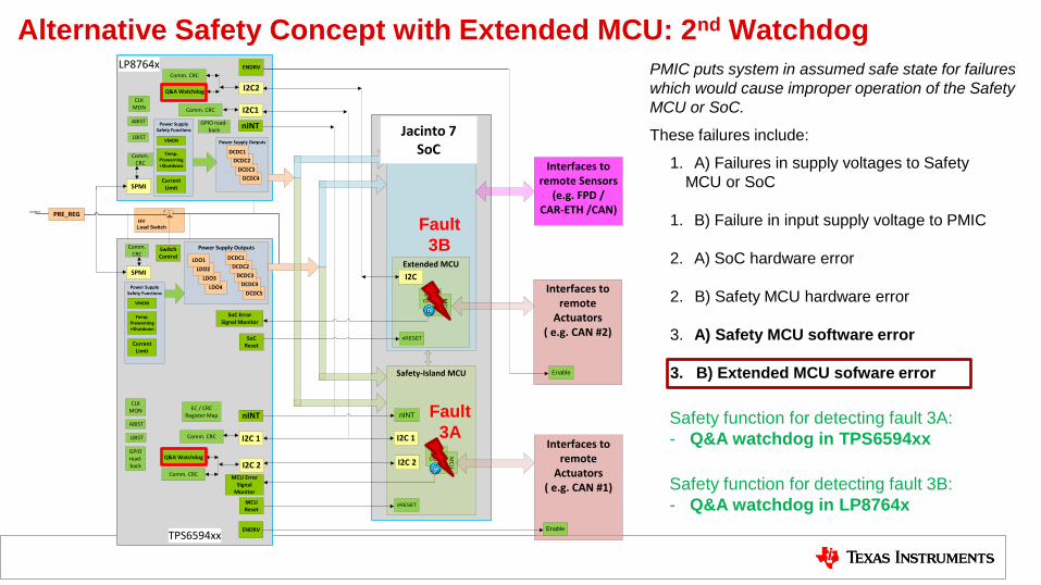
Alternative Safety Concept with Extended MCU: 2nd Watchdog
TPS6594xx
Power Supply Safety Functions
LP8764x
Power Supply Outputs
Power Supply Outputs
TI Application Processor
DCDC5LDO4
Safety-Island MCU
VSUPPLY
VMON
PRE_REG HV
Load Switch
Q&A Watchdog
MCU Error Signal
Monitor
I2C 2MCU
CORE
MC
U
CO
RE
MCU Reset
SoC Reset
nRESET
SoC
nINT
DCDC4
DCDC3
DCDC2
DCDC1
LDO3
LDO2
LDO1
DCDC4
DCDC3
DCDC2
DCDC1
Switch Control
SPMI
SPMI
Temp. Prewarning +Shutdown
Current Limit
ABIST
CLKMON
LBIST
EC / CRC Register Map
Comm. CRC
SoC Error Signal Monitor
GPIO read-back
ENDRV
Comm. CRC
Comm. CRC
ABIST
CLKMON
LBIST
GPIO read-back
I2C1
nINT
Comm. CRC
Power Supply Safety Functions
VMON
Temp. Prewarning +Shutdown
Current Limit
I2C 2
I2C 1
nINT
Interfaces to remote
Actuators ( e.g. CAN #1)
Enable
Interfaces to remote Sensors
(e.g. FPD / CAR-ETH /CAN)
I2C 2
I2C 1
Extended MCU
I2C
MCU
CORE
MC
U
CO
RE
nRESET
I2C2
Interfaces to remote
Actuators ( e.g. CAN #2)
Q&A Watchdog
Comm. CRC
Comm. CRC
ENDRV
Enable
PMIC puts system in assumed safe state for failures
which would cause improper operation of the Safety
MCU or SoC.
These failures include:
1. A) Failures in supply voltages to Safety
MCU or SoC
1. B) Failure in input supply voltage to PMIC
2. A) SoC hardware error
2. B) Safety MCU hardware error
3. A) Safety MCU software error
3. B) Extended MCU sofware error
Fault
3B
Safety function for detecting fault 3A:
- Q&A watchdog in TPS6594xx
Fault
3A
Safety function for detecting fault 3B:
- Q&A watchdog in LP8764x
Jacinto 7 SoC

Thank you for joining.
37
SLYP686
IMPORTANT NOTICE AND DISCLAIMER
TI PROVIDES TECHNICAL AND RELIABILITY DATA (INCLUDING DATASHEETS), DESIGN RESOURCES (INCLUDING REFERENCE DESIGNS), APPLICATION OR OTHER DESIGN ADVICE, WEB TOOLS, SAFETY INFORMATION, AND OTHER RESOURCES “AS IS” AND WITH ALL FAULTS, AND DISCLAIMS ALL WARRANTIES, EXPRESS AND IMPLIED, INCLUDING WITHOUT LIMITATION ANY IMPLIED WARRANTIES OF MERCHANTABILITY, FITNESS FOR A PARTICULAR PURPOSE OR NON-INFRINGEMENT OF THIRD PARTY INTELLECTUAL PROPERTY RIGHTS.These resources are intended for skilled developers designing with TI products. You are solely responsible for (1) selecting the appropriate TI products for your application, (2) designing, validating and testing your application, and (3) ensuring your application meets applicable standards, and any other safety, security, or other requirements. These resources are subject to change without notice. TI grants you permission to use these resources only for development of an application that uses the TI products described in the resource. Other reproduction and display of these resources is prohibited. No license is granted to any other TI intellectual property right or to any third party intellectual property right. TI disclaims responsibility for, and you will fully indemnify TI and its representatives against, any claims, damages, costs, losses, and liabilities arising out of your use of these resources.TI’s products are provided subject to TI’s Terms of Sale (www.ti.com/legal/termsofsale.html) or other applicable terms available either on ti.com or provided in conjunction with such TI products. TI’s provision of these resources does not expand or otherwise alter TI’s applicable warranties or warranty disclaimers for TI products.
Mailing Address: Texas Instruments, Post Office Box 655303, Dallas, Texas 75265Copyright © 2020, Texas Instruments Incorporated