j11 29 14 jiiu1|nm|| · pdf fileuses the diode-laser injection current to control the laser...
TRANSCRIPT
AD-A273 249
R&T 4124128
MATTER-WAVE INTERFEROMETRY WITH LASER COOLED ATOMS
David McIntyre
Department of Physics, Oregon State University, Corvallis, OR 97331-6507
DTIC ~Grant No: N00014-91-J-1 198ELECTEinal Technical Report, November 1993
1WV 3 01993 1,
"AI I This document .'-zs ze.&n appzoved"I. !for public telease and sole; its
1. Introduction distribution is inlisted.
This research program is concerned with matter-wave interferometry of laser cooled atoms.
A slow beam of laser cooled rubidium atoms will be used as the matter-wave source. The atom
optical elements are microfabricated amplitude transmission gratings which will be used in a three-
grating interferometer to split and recombine the rubidium beam. The atomic interferometer will be
a useful new tool with which to perform precision experiments in atomic physics, quantum optics,
and gravitation.
The research program takes advantage of three new technologies, the combination of which
provides a unique opportunity to construct a compact and stable interferometer. The techniques of
laser cooling and trapping are used to produce cold rubidium atoms in a well collimated beam.
Commercially available diode lasers with optical feedback frequency stabilization are used for the
laser cooling and trapping beams and for atomic beam diagnostics. Finally, submicron
twansmission gratings made with high-resolution electron-beam lithography are used as the
coherent beam splitters of the atomic interferometer. Figure 1 shows the proposed interferometer
geometry with the two paths that are generally used in such a device. The three-grating Bonse-
Hart interferometer is a particularly useful design since it has intrinsically equal path lengths and is
relatively insensitive to misalignments.1, 2 Figure 2 shows a schematic of our experiment in which
the matter-wave source is a laser cooled rubidium atomic beam. A thermal beam of rubidium
atoms is first slowed using chirped laser cooling.3,4 The slow atoms drift into a two-
93-29240 ;93 j11 29 1 14 JIIU1|nm||

x
SI ID I
Y z
•Input I I Output
Beam I I B I Beams
L L
Fig. 1. Three-grating Bonse-Hart interferometer with two-path interference configuration shown.
fA Chirped
S• • &. cooling
Kt~zzf-Af
Rb f-Aff
Fig. 2. Experimental schematic for three-grating interferometry with laser cooled atomic beam. The pieces of the
magnetic field coils shown in bold are the ones mainly responsible for the two-dimensional quadnipole field forming
the funnel.
2
dimensional magnetic quadrupole field in which six laser beaniE intersect to form a two-
dimensional magneto-optic trap or so-called atomic funneL5 The atoms experience molasses-type
damping in all three dimensions and are trapped in the two dimensions transverse to the axis of the
trap. Along the axis of the trap, the atoms move with a velocity determined by the intersecting
laser beam frequencies. We have planned for a mean atomic velocity of 10 m/s, corresponding to
a de Broglie wavelength of 0.5 nm. The emerging atomic beam will have a temperature of
approximately 500 pK, corresponding to a coherence length of 50 wavelengths. The beam will
then enter the three-grating interferometer. The amplitude transmission gratings have a period of
250 nm and are made from free-standing silicon nitride films on silicon substrates. 6 The three
gratings will be separated by 5 cm and will diffract the rubidium beam by 2 mrad into the first
order. Compared to the other interferometers which have been demonstrated using material
structures, 7 ours is relatively compact. The ability to tune the velocity of the funnel output beam
also provides our experiment with another degree of flexibility.
In the 2 and three-quarters years since this project began, progress has taken place along
several parallel fronts. We have constructed much of the apparatus and have produced the cooled
atomic beam source. We are now working on characterizing the cold atomic beam and directing it
into the atom interferometer.
IL Diode laser frequency stabilization
Our original diode-laser systems used optical-feedback stabilization from Fabry-Perot
confocal cavities.8, 9 We have since redirected our efforts to building and using diode-laser
systems that use diffraction gratings as the feedback element.' 0 These lasers are simpler to
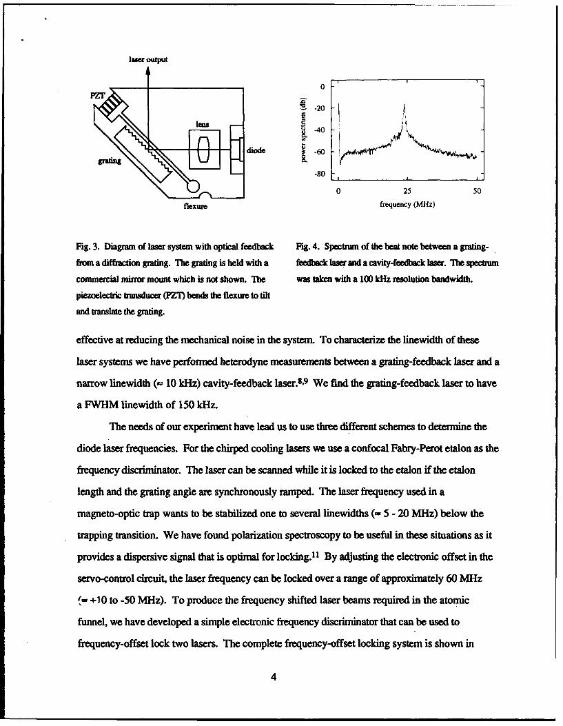
implement and have comparable performance. Figure 3 shows a schematic of the laser system. A
holographic grating at the Littrow angle provides the optical feedback. The laser diode, collimator
lens, and grating are all mounted on a small aluminum block for mechanical and thermal stability. -
Residual mechanical vibrations of the extended cavity are reduced with a servo-control system that
uses the diode-laser injection current to control the laser frequency. The electronic servo-control A
loop has a unity-gain frequency (n 100 kHz) far above any mechanical resonances, so is very .;I /DTTC QUALITY INSPECTED a ,v3 I ; •.c -s
3
4iA Sta
laser output
0PZT
E -20
-40
-80
0 25 50
flexure frequency (MHz)
Fig. 3. Diagram of laser system with optical feedback Fig. 4. Spectrum of the beat note between a grating-
from a diffraction grating. The grating is held with a feedback laser and a cavity-feedback laser. The spectrum
commercial mirror mount which is not shown. The was taken with a 100 kHz resolution bandwidth.
piezoelectric transducer (PZT) bends the flexure to tilt
and translate the grating.
effective at reducing the mechanical noise in the system. To characterize the linewidth of these
laser systems we have performed heterodyne measurements between a grating-feedback laser and a
narrow linewidth (- 10 kHz) cavity-feedback laser.8,9 We find the grating-feedback laser to have
a FWHM linewidth of 150 kHz.
The needs of our experiment have lead us to use three different schemes to determine the
diode laser frequencies. For the chirped cooling lasers we use a confocal Fabry-Perot etalon as the
frequency discriminator. The laser can be scanned while it is locked to the etalon if the etalon
length and the grating angle are synchronously ramped. The laser frequency used in a
magneto-optic trap wants to be stabilized one to several linewidths (- 5 - 20 MHz) below the
trapping transition. We have found polarization spectroscopy to be useful in these situations as it
provides a dispersive signal that is optimal for locking.11 By adjusting the electronic offset in the
servo-control circuit, the laser frequency can be locked over a range of approximately 60 MHz
+ +10 to -50 MHz). To produce the frequency shifted laser beams required in the atomic
funnel, we have developed a simple electronic frequency discriminator that can be used to
frequency-offset lock two lasers. The complete frequency-offset locking system is shown in
4

laser 1`
photodiode f f,
amplifier
comparator
inverter -F•-LFL -1i L_ ,1/f
digital trigger r Iinput delay (T) i i
servo amplifier
Fig. 5. Schematic of frequency-offset locking system. Not shown is the system used to stabilize laser 2 to a
confocal etalon or a rubidium resonance.
Fig. 5. The frequency discriminator consists primarily of a fast comparator to convert the
sinusoidal beat note into a digital signal, and a digitally controllable delay generator with delay T.
The delay generator output has a duty cycle of 1/2 -fT, wheref is the frequency of the beat note.
A low pass filter produces a signal proportional to the duty cycle, which thus allows linear
frequency discrimination from near dc tof= 1/2T. Using this system, we have been able to
continuously tune the offset frequency from 2-30 MHz.
These diode-laser systems allow us to produce single-mode, narrow-band radiation that
may be (1) tuned over 5 -10 GHz with several hundred hertz repetition rates, (2) stabilized to an
atomic resonance with excellent long-term stability, or (3) frequency offset from a second laser
with a digitally-controllable offset frequency in the range of 2-30 MHz. We have taken advantage
of new, higher power diodes which have become available and we now have up to 35 mW
available from some of these lasers. We now have ten grating-feedback laser systems working in
our laboratory.
5

We have also demonstrated a new stabilization technique for diode lasers that uses optical
feedback to lock the diode laser frequency to an atomic resonance. This technique takes advantage
of the high-contrast transmission spectra that can be obtained with Doppler-free saturation
spectroscopy in optically thick saniples.lZ 3 The simple experimental set-up is depicted in Fig. 6.
In this scheme, the laser beam passes through a beamsplitter and is incident into an atomic vapor
cell as the pump beam. After being attenuated by the vapor, the pump beam is retroreflected and
used as the counterpropagating probe beam. The probe transmission signal is monitored via the
beamsplitter. The vapor cell is heated so that the atomic sample is optically thick to radiation of
moderate intensity within the Doppler profile. At line center, however, the strong pump beam
bleaches a hole in the sample for the weaker probe beam. With the laser optically isolated or the
return beam slightly misaligned, a probe transmission spectrum such as that shown in Fig. 7,
curve (b), is obtained. This spectrum resembles that of standard saturation spectroscopy (Fig. 7,
curve (a)), except that the Doppler-free signal is virtually background free with the proper choice of
cell temperature. Within the Doppler profile, the probe transmission resembles the transmission
through an optical cavity; that is, the transmission is high on resonance and nearly zero off
resonance. With the return beam aligned properly, the laser experiences optical feedback at
frequencies where hole burning is effective. In the case of rubidium, optical pumping causes the
dominant peaks in the spectrum to be crossover resonances between the upper-state hyperfine
levels. Outside the Doppler profile, there is optical feedback that is not frequency selective. A
typical probe transmission spectrum is shown in Fig. 7, curve (c). The nearly fiat-topped peak at
the location of one of the crossover resonances demonstrates that the laser frequency abruptly
jumps onto the resonance and remains locked there while the laser would otherwise be scanning.
The locking range is approximately 100 MHz. We have measured the linewidth of this stabilized
laser system to be 250 kHz, more than two orders of magnitude less than the free-running
linewidth.
6

output
nua (c) (a)
g diode ensitydaser RR cell fllte) mirror(ba n
bramsplitter PZT ma
efetdeteonor _____________________ The-1000 -500 0 500
detuniog (MHz)
Fig. 6. Experimental schematic of diode laser stabilized Fig. 7. Probe IL-am transmission spectir of the F - 2
with opticalfeedbackfoanopticallythickrubidium to h F be1, 2,dacd 3vhypfe sitioals ofthee D2
cyline of Rb. Cauem (a) is a standard saturated tabsorption spectrum in a room temperature cell
showing theF=2toF=3 transition (at zero
detuning) and two crossover resonances. Curves (b) and
(c) are for the caue of the optically thick rbidium cell.
For curve (b) the probe beam was sightly misangned
so as to avoid optical feedback. Curve (c) shows the
effect of optical feedback on the laser frequency. The
curves have been displaed vertically from each other for
clarity. The baselines on curves (b) and (c) represent
zero probe beam tranismission.
HLL Rubidium. atomic funnel
The atomic beam and atom interferometer are housed in a two-chamnber, differentially
pumped vacuum system. The source chamber is pumped with a turbomolecular pump and has a
base pressure of 2 x 10⁻⁸ Toff and an operating pressure of 6 x 10⁻⁷ when the rubidium oven is
heated to produce the beam. The rubidium oven has a recirculator so that rubidium can be recycled
to increase the time between oven refills. 14 The atomic funnel and interferometer are housed in a
high vacuum chamber that is pumped with a trapped diffusion pump and has a base pressure of
3 x 10⁻⁹ Torr. The high vacuum chamber consists of a sphere with the funnel at its center and an
7
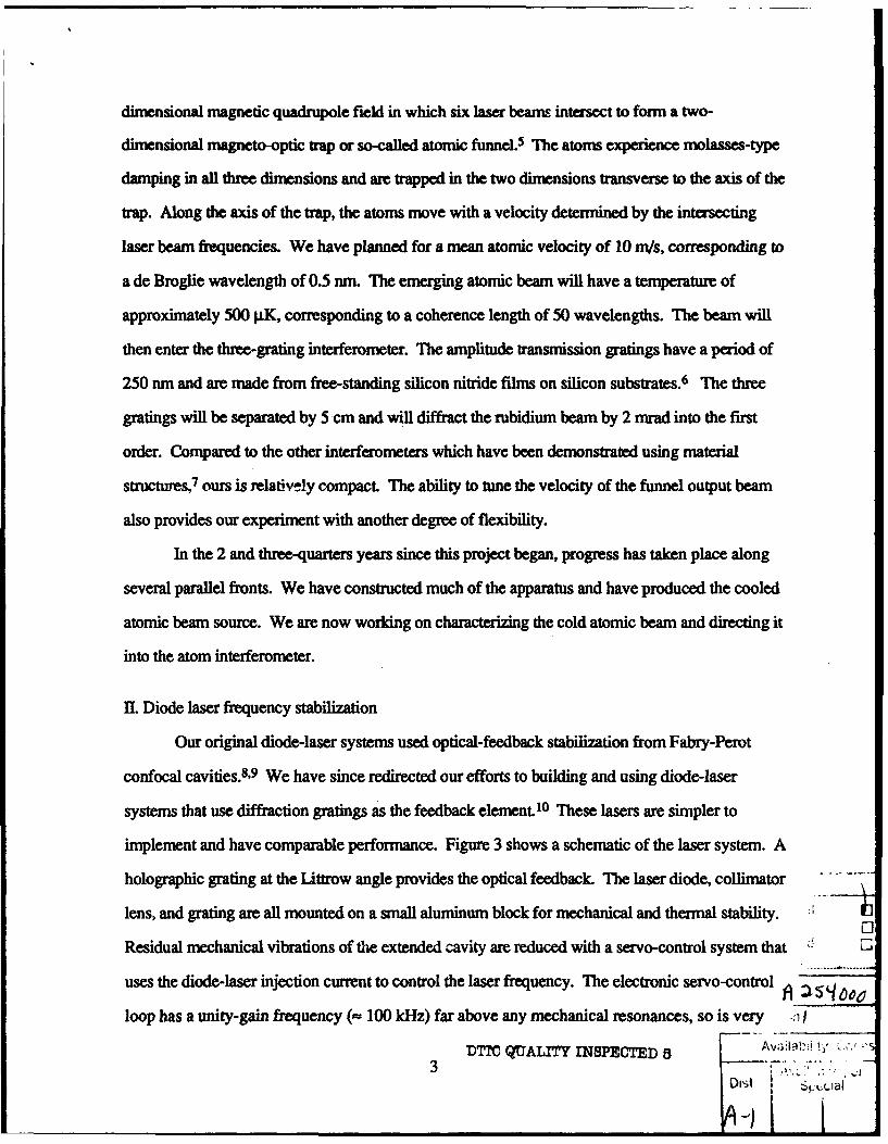
adjacent cylinder for the atom interferometer. These two pieces were designed so that they can be
attached in several different configurations with the pump on either chamber. This flexibility will
be useful should we desire to try other possible interferometer configurations.
With this system, we have slowed a tmnal rubidium beam and loaded a three-dimensional
and a two-dimensional magneto-optic trap (MOT). Rubidium atoms from the oven are slowed and
cooled by the scattering force from a counterpropagating laser beam tuned below the F = 3 to
F" = 4 hyperfine transition of the D2 line of 8SRb. During the cooling, the laser frequency is
ramped toward the resonance frequency to compensate for the decreasing Doppler shift of the
decelerating atoms.3.4 By adjusting the frequency of the laser at the end of this ramp, we can
control the characteristic velocity of the cooled beam, which is important for loading the atoms into
a trap.15 A second chirped diode laser is used to counteract optical pumping of the atoms to the
other hyperfine level of the ground state.
We first loaded these slow atoms into a three-dimensional MOT, which is formed by six
laser beams intersecting at the center of a pair of coils used to produce a spherical quadrupole
magnetic field.16 Each pair of counterpropagating beams has opposite circular polarizations. The
beams were all derived from one laser, and a second laser was again used to counteract optical
pumping. The beams are tuned below resonance and provide molasses-type damping as well as a
restoring force to the zero point of the magnetic field. We used this three-dimensional trap to test
our laser cooling techniques and our vacuum system and then moved on to the two-dimensional
funnel configuration5,17 which will produce the slow beam needed for our interferometer.
The coils that produce the two-dimensional quadrupole magnetic field are shown in Fig. 2.
The funnel is presently oriented horizontally. Three lasers at frequenciesf andf± Af are used,
with the laser at frequencyf used for the vertical pair of beams. In the horizontal plane, the laser
beams are aligned at 450, with the two beams coming toward the funnel output beam at frequency
f- Af and the two beams coming from behind at frequency f+ Af. This should produce a beam
of atoms moving along the axis of the magnetic field with a mean velocity of -F Af X. The three
lasers are each frequency-offset locked to a fourth reference laser that is stabilized to the rubidium
8
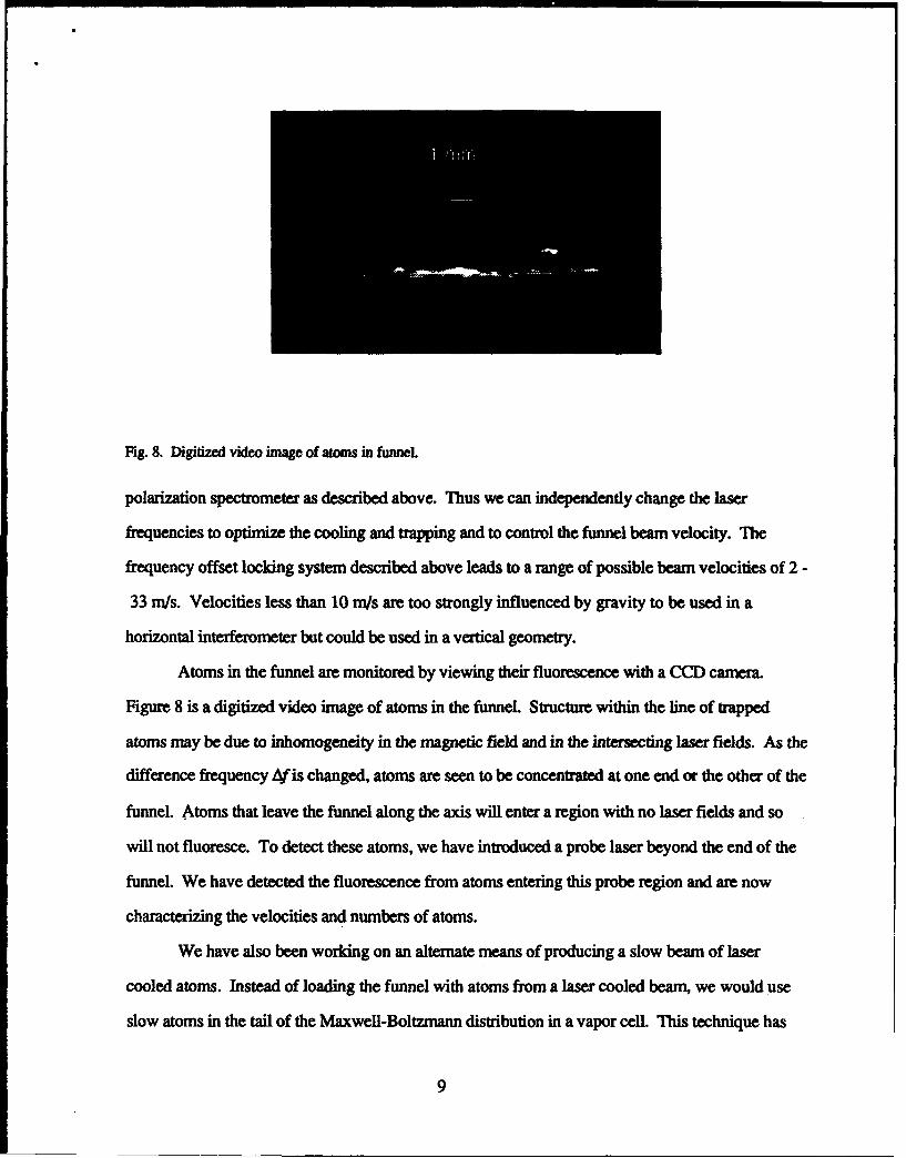
Fig. 8. Digitized video image of atoms in funnel
polarization spectrometer as described above. Thus we can independently change the laser
frequencies to optimize the cooling and trapping and to control the funnel beam velocity. The
frequency offset locking system described above leads to a range of possible beam velocities of 2 -
33 m/s. Velocities less than 10 m/s are too strongly influenced by gravity to be used in a
horizontal interferometer but could be used in a vertical geometry.
Atoms in the funnel are monitored by viewing their fluorescence with a CCD camera.
Figure 8 is a digitized video imageof atoms in the funneL Structure within the line of trapped
atoms may be due to inhomogeneity in the magnetic field and in the intersecting laser fields. As the
difference frequency 4f is changed, atoms are seen to be concentrated at one end or the other of the
funnel. Atoms that leave the funnel along the axis will enter a region with no laser fields and so
will not fluoresce. To detect these atoms, we have introduced a probe laser beyond the end of the
funnel. We have detected the fluorescence from atoms entering this probe region and are now
characterizing the velocities and numbers of atoms.
We have also been working on an alternate means of producing a slow beam of laser
cooled atoms. Instead of loading the funnel with atoms from a laser cooled beam, we would use
slow atoms in the tail of the Maxwell-Boltzmann distribution in a vapor cell. This technique has
9
been demonstrated for a three-dimensional MOT, 1s but not yet for the two-dimensional funnel
configuration. To test this idea, we have cooled and trapped atoms in a magneto-optic trap
contained in a small rubidium vapor celL We have used a three-dimensional spherical quadrupole
field formed by two round coils, a "stretched" quadrupole formed by two rectangular coils, and
most recently a pure two-dimensional field formed by two pairs of round coils. In this last
configuration, we have been able to see the atoms move around when a frequency shifted laser
beam is introduced, but we have not yet clearly seen a beam of atoms emerge from the trap.
IV. Grating fabrication
We have fabricated the amplitude transmission gratings to be used for the atom
interferometer. We performed the work at the National Nanofabrication Facility (NNF) at Cornell
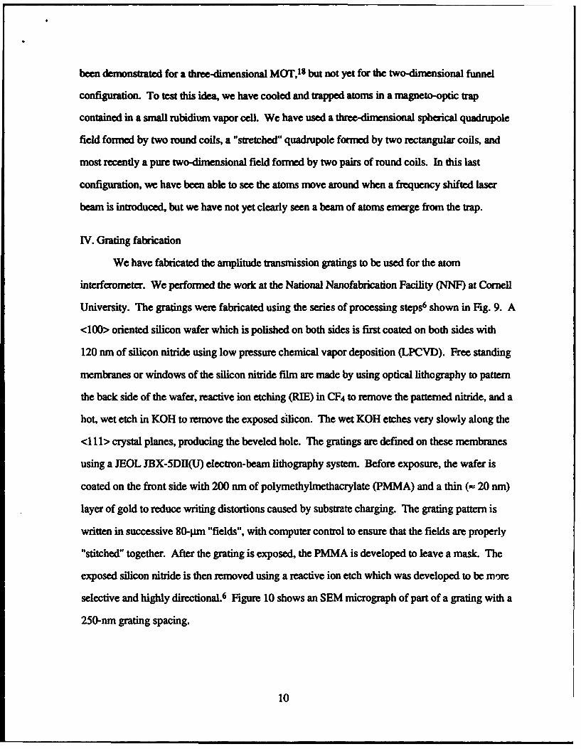
University. The gratings were fabricated using the series of processing steps6 shown in Fig. 9. A
<100> oriented silicon wafer which is polished on both sides is first coated on both sides with
120 nm of silicon nitride using low pressure chemical vapor deposition (LPCVD). Free standing
membranes or windows of the silicon nitride film are made by using optical lithography to pattern
the back side of the wafer, reactive ion etching (RIE) in CF4 to remove the patterned nitride, and a
hot, wet etch in KOH to remove the exposed silicon. The wet KOH etches very slowly along the
<111> crystal planes, producing the beveled hole. The gratings are defined on these membranes
using a JEOL JBX-5DII(U) electron-beam lithography system. Before exposure, the wafer is
coated on the front side with 200 nm of polymethylmethacrylate (PMMA) and a thin (- 20 nrn)
layer of gold to reduce writing distortions caused by substrate charging. The grating pattern is
written in successive 80-pm "fields", with computer control to ensure that the fields are properly
"stitched" together. After the grating is exposed, the PMMA is developed to leave a mask. The
exposed silicon nitride is then removed using a reactive ion etch which was developed to be more
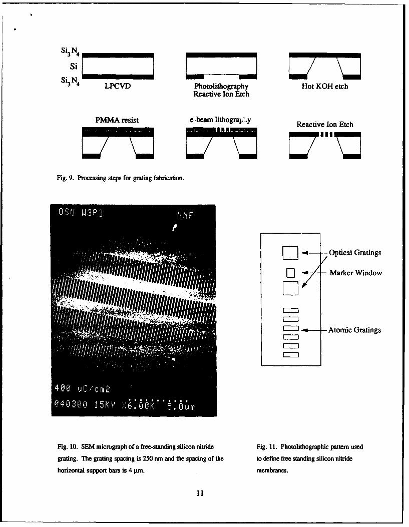
selective and highly directional. 6 Figure 10 shows an SEM micrograph of part of a grating with a
250-nm grating spacing.
10
Si 4 -7
Si N LPCV
3 4 LCDPhotolithography Hot KOH etchReactive Ion Etch
PMMA resist e-bearn lithograljy Reactive Ion Etch
Fig. 9. Processing steps for grating fabrication.
[] Optical Gratings
;7Z Marker Window
E~J Atomic Gratings
Fig. 10. SEM micrograph of a free-standing silicon nitride Fig. 11. Photolithographic pattern used
grating. The grating spacing is 250 mn and the spacing of the to define free standing silicon nitride
horizontal support bars is 4 pim. membranes.
I I

We have fabricated gratings with periods of 250 nm and 500 run and with total areas of
I mm. x 150 9m, 1 mm x 50 I~m, 0.5 mn x 150 gm, and 0.5 mmx 50 JIm. Each 3" wafer's
divided into 20 8 mm x 18 mm chips. Each chip has six atomic scale gratings, two larger optical
scale gratings, and a marker window, as shown in Fig. 11. We were not as successful with the
larger optical gratings (d = 8.4 pgm) as with the atomic gratings. We desi,,ned the optical gratings
for us, in optical alignment of the interferometer and made the windows . mm x 1 mm in area,
thinking that we could simply scale up the atomic gratings. However, the thickness of .he nitride
layer was obviously not scaled up, and this led to destruction of many of the optical gratings
during the last RIE step. We tied several methods and did meet with some success, though it was
inconsistent.
To test the coherence of the atomic gratings we arranged for the e-beam system to write
verniers on the silicon substrate. By comparing verniers written in adjacent fields, we could
determine the stitching errors. We found that the fields were correctly placed to within 10 nm
between subsequent fields and to within 50 nm overall. Since this is a small fraction of the
250 nm grating spacing, the gratings are quite coherent.
V. Personnel and publications
This research has been carried out with graduate students, undergraduate students, and a
post-doctoral researcher. Two advanced students are working toward the Ph.D. degree; one
student has received a M.S. degree and two others are nearing completion of M.S. degrees; and
one undergraduate student did a senior thesis for the B.S. degree.
Details of the grating-feedback diode laser stabilization work have recently been
published. 19 A paper on the optical stabilization to an atomic resonance has been submitted for
publication.2° Reports on the progress of the atom interferometer experiment have been presented
at two conferences. 2 1,22
12

ReferencesI B. . Chang, R. Alferness, and E. N. Leith, Appl. Opt. 14, 1592 (1975).
2 H. Mendlowitz and J. A. Simpson, 3. Opt. Soc. Am. 52, 520 (1962).
3 W. Ertmer, R. Blatt, J. L. Hall, and M. Zhu, Phys. Rev. Lett. 54, 996 (1985).4 R. N. Watts and C. E. Wieman, Opt. Lett. 11, 291 (1986).
5 E. Riis, D. S. Weiss, K. A. Moler, and S. Chu, Phys. Rev. Lett. 64, 1658 (1990).6 D. W. Keith, R. 3. Soave, and M. L. Rooks, 3. Vac. Sci. Technol. B 9, 2846 (1991).7 D. W. Keith, C. R. Ekstrom, Q. A. Turchette, and D. E. Pritchard, Phys. Rev. Lett. 66, 2693
(1991).8 B. Dahmani, L Holiberg, and R. Drullinger, Opt. Lett. 12, 876 (1987).
9 A. Hemmerich, D. H. McIntyre, D. Schropp, Jr., D. Meschede, and T. W. HAnsch, Opt.
Commun. 75, 118 (1990).10 C. F. Wieman and L. Hollberg, Rev. Sci. Instrum. 62, 1 (1991).
11 C. Wieman and T. W. Hltnsch, Phys. Rev. Lett. 36, 1170 (1976).
12 S. Svanberg, G.-Y. Yan, T. P. Duffey, and A. L. Schawlow, Opt. Lemt. 11, 138 (1986).
13 S. Svanberg, G.-Y. Yan, T. P. Duffey, W.-M. Du, T. W. Hlinsch, and A. L. Schawlow, J.
Opt. Soc. Am. B 4, 462 (1987).14 M. Lambropoulos and S. E. Moody, Rev. Sci. Instrum. 48, 131 (1977).
15 D. Sesko, C. G. Fan, and C. E. Wieman, J. Opt. Soc. Am. B 5, 1225 (1988)
16 E. L. Raab, M. Prentiss, A. Cable, S. Chu, and D. E. Pritchard, Phys. Rev. ',ett. 59, 2631
(1987).17 J. Nellessen, J. Werner, and W. Ertmer, Opt. Commun. 78, 300 (1990).18 C. Monroe, W. Swann, H. Robinson, and C. Wieman, Phys. Rev. Lett. 65, 1571 (1990).19 J.3. Maki, N. S. Campbell, C. M. Grande, R. P. Knorpp, and D. H. McIntyre, Opt.
Commun. 102, 251 (1993).20 C. J. Cuneo, J. J. Maki, and D. H. McIntyre, submitted to Applied Physics Letters.
21 D. H. McIntyre, H. Delfs, and T. B. Swanson, 1992 DAMOP Meeting, Chicago, Illinois,
May 20-22, 1992; Bull. Am. Phys. Soc. 37, 1139 (1992).22 H. Delfs, T. B. Swanson, and D. H. McIntyre, Book of Abstracts of the Thirteenth
International Conference on Atomic Physics, Munich, Germany, August 3-7, 1992.
13