j. wayde allen the dish antenna at the table mountain i10c site. j. wayde allen. 1. this paper...
TRANSCRIPT

NTIA Technical Memorandum 18-531
The Dish Antenna at the Table Mountain I10C Site
J. Wayde Allen

NTIA Technical Memorandum 18-531
The Dish Antenna at the Table Mountain I10C Site
J. Wayde Allen
U.S. DEPARTMENT OF COMMERCE
February 2018

DISCLAIMER
Certain commercial equipment, materials, and/or programs are identified in this report to specify adequately the experimental procedure. In no case does such identification imply recommendation or endorsement by the National Telecommunications and Information Ad-ministration, nor does it imply that the program or equipment identified is necessarily the best available for this application.
ii

CONTENTS
Page
1 Introduction . . . . . . . . . . . . . . . . . . . . . . . . . . . . . . . . . . . . . . . 1
2 System Architecture . . . . . . . . . . . . . . . . . . . . . . . . . . . . . . . . . . 3
3 Software . . . . . . . . . . . . . . . . . . . . . . . . . . . . . . . . . . . . . . . . . 7
4 Dish Pointing Calibration . . . . . . . . . . . . . . . . . . . . . . . . . . . . . . . 8
5 Tracking Limitations . . . . . . . . . . . . . . . . . . . . . . . . . . . . . . . . . . 11
6 Dish Operation . . . . . . . . . . . . . . . . . . . . . . . . . . . . . . . . . . . . . 14 6.1 Dish Startup . . . . . . . . . . . . . . . . . . . . . . . . . . . . . . . . . . . . 14 6.2 Dish Shutdown . . . . . . . . . . . . . . . . . . . . . . . . . . . . . . . . . . 15
7 Summary . . . . . . . . . . . . . . . . . . . . . . . . . . . . . . . . . . . . . . . . 17
iii

THE DISH ANTENNA AT THE TABLE MOUNTAIN I10C SITE
J. Wayde Allen1
This paper describes the design and retrofit of the 3.7 meter (12-foot) dish antenna located near building I10C at the U.S. Department of Commerce Table Mountain Field Site and Radio Quiet Zone.
Key words: dish antenna; radio; RF; Table Mountain
1 INTRODUCTION
Figure 1: Picture of the I10C dish antennas.
In 2001 the National Oceanic and Atmospheric Administration’s (NOAA) Space Weather Prediction Center transferred the two dishes near building I10C at the U.S. Department of Commerce Table Mountain Field Site and Radio Quiet Zone to the Institute for Telecom-munication Sciences (ITS). Prior to this, NOAA had been using these dishes to record data from their Geostationary Operational Environmental Satellites (GOES), and there had been little need for motor driven tracking control. The dishes were simply hand cranked into position. However, after the dishes were transferred to ITS, work began on the installation of a stepper motor tracking system on the East dish. This removed the need to hand crank the dish to a new location. Instead the dish can now be moved by simply commanding it to point in a new direction. This makes it much quicker and easier to point the dish. It
1The author is with the Institute for Telecommunication Sciences, National Telecommunications and Information Administration, U.S. Department of Commerce, Boulder, Colorado 80305.

also makes it possible to use the dish for tracking both non-geosynchronous satellites and celestial radio sources.
The control system for the East dish is the prototype. Ultimately, the plan is to duplicate the control system on the West dish as well since it is identical in construction. A picture of these dishes can be seen in Figure 1. This paper serves to document the design, construction, and basic operation of this control system.
2
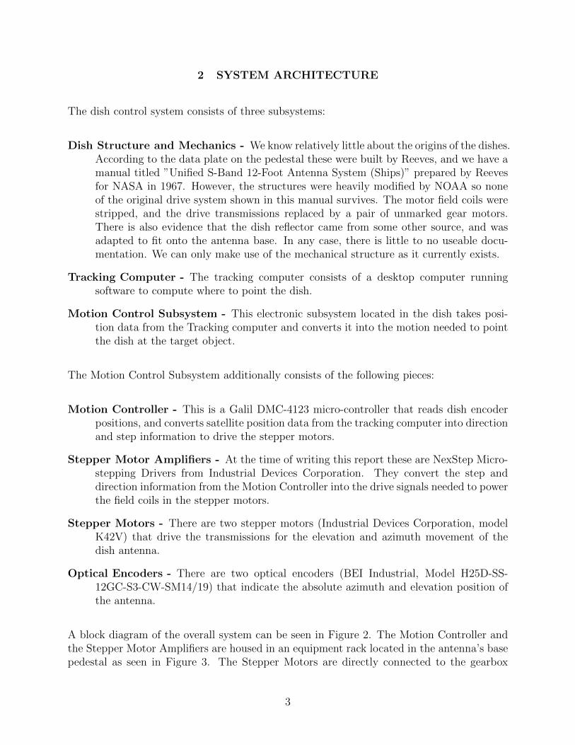
2 SYSTEM ARCHITECTURE
The dish control system consists of three subsystems:
Dish Structure and Mechanics - We know relatively little about the origins of the dishes. According to the data plate on the pedestal these were built by Reeves, and we have a manual titled ”Unified S-Band 12-Foot Antenna System (Ships)” prepared by Reeves for NASA in 1967. However, the structures were heavily modified by NOAA so none of the original drive system shown in this manual survives. The motor field coils were stripped, and the drive transmissions replaced by a pair of unmarked gear motors. There is also evidence that the dish reflector came from some other source, and was adapted to fit onto the antenna base. In any case, there is little to no useable docu-mentation. We can only make use of the mechanical structure as it currently exists.
Tracking Computer - The tracking computer consists of a desktop computer running software to compute where to point the dish.
Motion Control Subsystem - This electronic subsystem located in the dish takes posi-tion data from the Tracking computer and converts it into the motion needed to point the dish at the target object.
The Motion Control Subsystem additionally consists of the following pieces:
Motion Controller - This is a Galil DMC-4123 micro-controller that reads dish encoder positions, and converts satellite position data from the tracking computer into direction and step information to drive the stepper motors.
Stepper Motor Amplifiers - At the time of writing this report these are NexStep Micro-stepping Drivers from Industrial Devices Corporation. They convert the step and direction information from the Motion Controller into the drive signals needed to power the field coils in the stepper motors.
Stepper Motors - There are two stepper motors (Industrial Devices Corporation, model K42V) that drive the transmissions for the elevation and azimuth movement of the dish antenna.
Optical Encoders - There are two optical encoders (BEI Industrial, Model H25D-SS-12GC-S3-CW-SM14/19) that indicate the absolute azimuth and elevation position of the antenna.
A block diagram of the overall system can be seen in Figure 2. The Motion Controller and the Stepper Motor Amplifiers are housed in an equipment rack located in the antenna’s base pedestal as seen in Figure 3. The Stepper Motors are directly connected to the gearbox
3

transmissions that move the dish structure as seen in Figure 4. The optical encoders are directly connected to axles for both the azimuth and elevation as seen in Figure 5.
As noted, the Motion Control Subsystem is built in a standard 19 inch equipment rack with the Galil DMC-4123 control computer, it’s DC power supply, and the two motor amplifiers mounted to an aluminum mounting plate recessed in the box. This can be seen in Figure 3.
Connections to the Galil DMC4123 are made through a series of D-style connectors as shown in Figure 6. There are two 26-pin connectors, one for each of the axes of motion, and one 44-pin connector for general I/O connections. To make it easier to wire up the control box, these cables are routed to a break out panel with screw type connectors located in the bottom of the equipment rack as seen in Figure 7. The pin numbers on the break out panel match the pin numbers on the DMC-4123 connectors, and Table 1 shows the pin number, the pin label, and the wire color in the cable bundle. A detailed description of the pin labels and their function can be found in the DMC-4123 manual which can be downloaded from the manufacturer’s web page.
Table 1: 26 Pin Cable Pinout
Connector Pin Pin Label Wire Color 1 HALC Black 2 AEN White 3 DIR Red 4 HOM Yellow 5 LSCOM0 Violet 6 AA- Blue 7 MI+ Brown 8 MA- Green 9 +5V Gray 10 GND Light Blue 11 ENBL- Orange 12 HALB Light Green 13 STP Pink 14 FLS White/Black 15 AB+ Red/Black 16 MI- Yellow/Black 17 MB+ Violet/Black 18 GND Green/Black 19 MCMD Orange/Black 20 ENBL+ Blue/Black 21 HALA Brown/Black 22 RLS Gray/Black 23 AB- Light Blue/Black 24 AA+ Light Green/Black 25 MB- Pink/Black 26 MA+ Blue/White
4

Figure 8 describes the cable that connects between the break out panel and the plug on the motor amplifier. The cable connections between the motor amplifiers and the motor connector located on the top of the control rack can be seen in Figure 9. Wiring for the cable that runs between the equipment rack and the motor can be seen in Figure 10.
Table 2 shows the connections between the 44-pin I/O wiring plug on the DMC-4123 and the break out panel. This provides easy access to the auxiliary I/O connections available on the DMC-4123. At present we are not using these connections, but the break out board is included to make it possible to easily add connections to these as needed for future modifi-cations and additions to the system.
Figure 11 describes wiring for the optical encoders.
The Tracking Computer is connected to the dish Motion Controller via a standard Ethernet cable. The communications protocol is TCP/IP.
Table 2: 44 Pin I/O Cable Pinout
Connector Pin Pin Label Wire Color 1 ERR Black 2 DI1 White 3 DI4 Red 4 DI7 Yellow 5 ELO Violet 6 LSCOM0 Blue 7 HOMA Brown 8 HOMB Green 9 HOMC Gray 10 HOMD Light Blue 11 OP0A Orange 12 DO3 Light Green 13 DO6 Pink 14 OP0B White/Black 15 +5V Red/Black 16 RST Yellow/Black 17 INCOM0 Violet/Black 18 DI3 Green/Black 19 DI6 Orange/Black 20 ABRT Blue/Black 21 N/C Brown/Black 22 RLSA Gray/Black 23 RLSB Light Blue/Black 24 RLSC Light Green/Black
5

Table 2: 44 Pin I/O Cable Pinout
Connector Pin Pin Label Wire Color 25 RLSC Pink/Black 26 OP0A Orange/White 27 DO2 Red/White 28 DO5 Violet/White 29 DO8 Brown/White 30 +5V Green/White 31 GND Blue/White 32 DI2 Gray/Red 33 DI5 Light Green/Red 34 DI8 Light Blue/Red 35 GND Pink/Red 36 FLSA Yellow/Red 37 FLSB Violet/Red 38 FLSC Gray/Green 39 FLSD Orange/Green 40 GND Red/Green 41 DO1 Violet/Green 42 DO4 Brown/Green 43 DO7 Light Blue/Green 44 CMP Light Green/Green
6
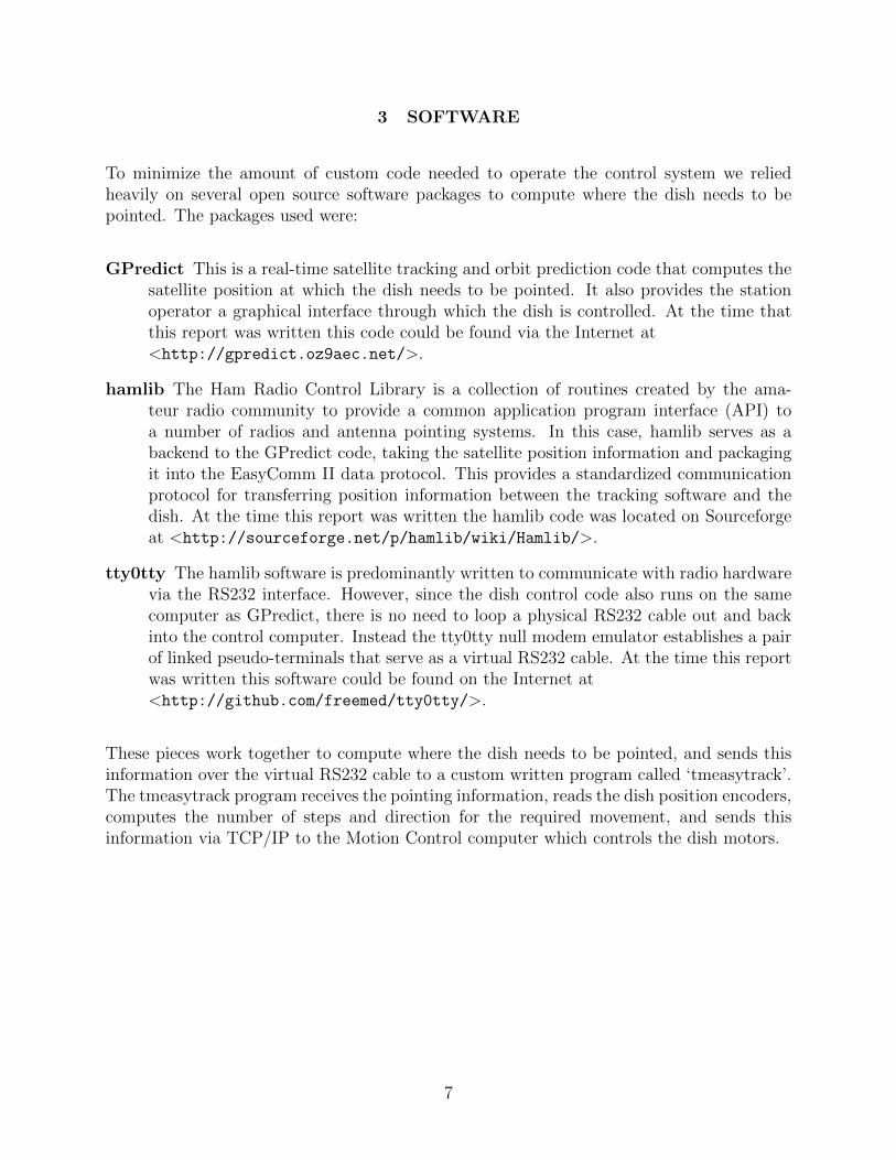
3 SOFTWARE
To minimize the amount of custom code needed to operate the control system we relied heavily on several open source software packages to compute where the dish needs to be pointed. The packages used were:
GPredict This is a real-time satellite tracking and orbit prediction code that computes the satellite position at which the dish needs to be pointed. It also provides the station operator a graphical interface through which the dish is controlled. At the time that this report was written this code could be found via the Internet at <http://gpredict.oz9aec.net/>.
hamlib The Ham Radio Control Library is a collection of routines created by the ama-teur radio community to provide a common application program interface (API) to a number of radios and antenna pointing systems. In this case, hamlib serves as a backend to the GPredict code, taking the satellite position information and packaging it into the EasyComm II data protocol. This provides a standardized communication protocol for transferring position information between the tracking software and the dish. At the time this report was written the hamlib code was located on Sourceforge at <http://sourceforge.net/p/hamlib/wiki/Hamlib/>.
tty0tty The hamlib software is predominantly written to communicate with radio hardware via the RS232 interface. However, since the dish control code also runs on the same computer as GPredict, there is no need to loop a physical RS232 cable out and back into the control computer. Instead the tty0tty null modem emulator establishes a pair of linked pseudo-terminals that serve as a virtual RS232 cable. At the time this report was written this software could be found on the Internet at <http://github.com/freemed/tty0tty/>.
These pieces work together to compute where the dish needs to be pointed, and sends this information over the virtual RS232 cable to a custom written program called ‘tmeasytrack’. The tmeasytrack program receives the pointing information, reads the dish position encoders, computes the number of steps and direction for the required movement, and sends this information via TCP/IP to the Motion Control computer which controls the dish motors.
7
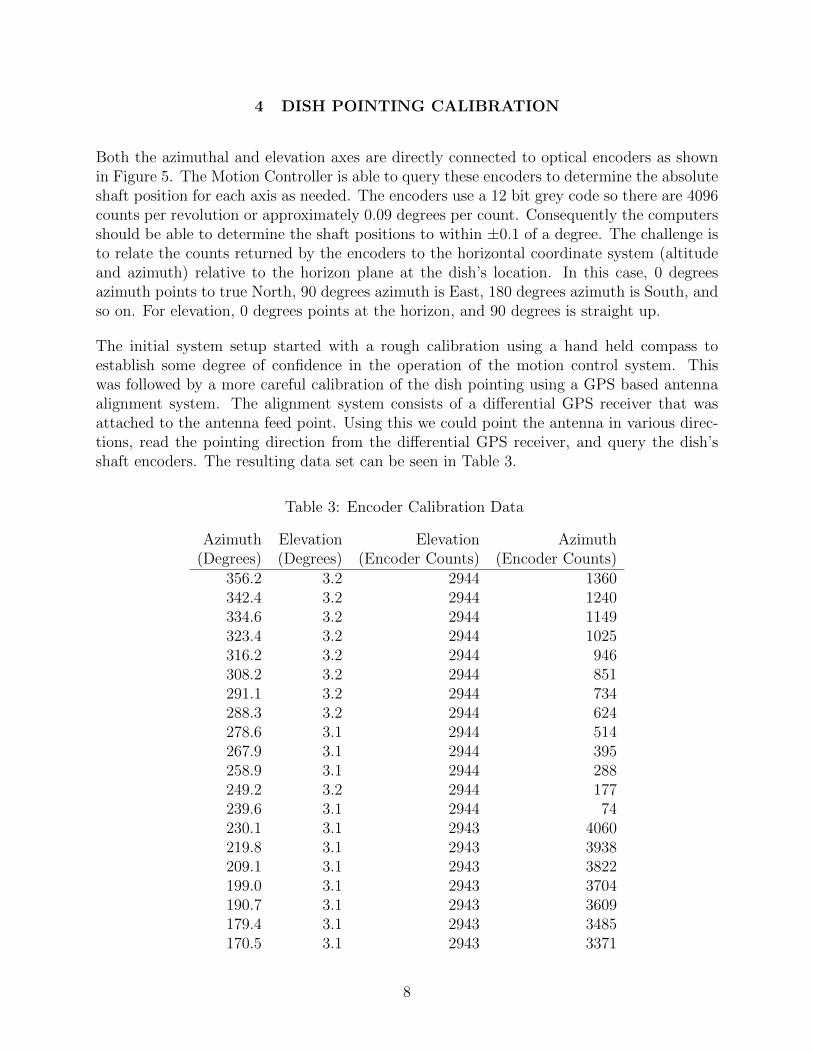
4 DISH POINTING CALIBRATION
Both the azimuthal and elevation axes are directly connected to optical encoders as shown in Figure 5. The Motion Controller is able to query these encoders to determine the absolute shaft position for each axis as needed. The encoders use a 12 bit grey code so there are 4096 counts per revolution or approximately 0.09 degrees per count. Consequently the computers should be able to determine the shaft positions to within ±0.1 of a degree. The challenge is to relate the counts returned by the encoders to the horizontal coordinate system (altitude and azimuth) relative to the horizon plane at the dish’s location. In this case, 0 degrees azimuth points to true North, 90 degrees azimuth is East, 180 degrees azimuth is South, and so on. For elevation, 0 degrees points at the horizon, and 90 degrees is straight up.
The initial system setup started with a rough calibration using a hand held compass to establish some degree of confidence in the operation of the motion control system. This was followed by a more careful calibration of the dish pointing using a GPS based antenna alignment system. The alignment system consists of a differential GPS receiver that was attached to the antenna feed point. Using this we could point the antenna in various direc-tions, read the pointing direction from the differential GPS receiver, and query the dish’s shaft encoders. The resulting data set can be seen in Table 3.
Table 3: Encoder Calibration Data
Azimuth Elevation Elevation Azimuth (Degrees) (Degrees) (Encoder Counts) (Encoder Counts)
356.2 3.2 2944 1360 342.4 3.2 2944 1240 334.6 3.2 2944 1149 323.4 3.2 2944 1025 316.2 3.2 2944 946 308.2 3.2 2944 851 291.1 3.2 2944 734 288.3 3.2 2944 624 278.6 3.1 2944 514 267.9 3.1 2944 395 258.9 3.1 2944 288 249.2 3.2 2944 177 239.6 3.1 2944 74 230.1 3.1 2943 4060 219.8 3.1 2943 3938 209.1 3.1 2943 3822 199.0 3.1 2943 3704 190.7 3.1 2943 3609 179.4 3.1 2943 3485 170.5 3.1 2943 3371
8

Table 3: Encoder Calibration Data
Azimuth Elevation Elevation Azimuth (Degrees) (Degrees) (Encoder Counts) (Encoder Counts)
157.7 3.1 2944 3236 149.6 3.1 2944 3148 139.2 3.1 2944 3026 127.5 3.1 2944 2893 119.9 3.1 2944 2802 108.5 3.1 2944 2677 99.3 3.1 2944 2572 89.4 3.1 2944 2461 78.5 3.1 2944 2334 68.0 3.2 2944 2221 59.3 3.2 2944 2125 49.6 3.2 2944 2010 39.2 3.2 2944 1891 29.3 3.2 2944 1780 18.1 3.2 2944 1655 9.3 3.3 2944 1548
359.9 3.3 2944 1443 270.1 3.2 2943 432 270.5 -0.1 2980 432 271.2 10.7 2857 432 271.5 19.9 2754 432 270.7 31.1 2627 432 271.0 40.3 2522 432 270.6 50.2 2410 432 271.0 60.2 2297 432 268.6 69.9 2190 432 270.0 80.5 2073 432 253.0 90.8 1985 432
Figure 12 shows a plot of these data. The linearity of the plotted data suggested that we could simply fit these data to a line. resulting in the following:
Elcounts = −11.25 ∗ Eldegrees + 2979.3 (1)
Azcounts = 11.38 ∗ Azdegrees + 1441.8 (2)
where:
9

Elcounts is the count value read from the elevation encoder
Eldegrees is the elevation angle in degrees
Azcounts is the count value read from the azimuthal encoder, and
Azdegrees is the azimuthal angle in degrees.
Further testing needs to be done to determine the pointing accuracy obtained with this calibration, but the fact that we have been able to track and receive signals from a number of satellites indicates that this is close. It is important to note that any changes to the coupling between either of the encoders or the dish drive hubs will change the intercept points in these equations, and force a re-calibration.
10

5 TRACKING LIMITATIONS
There are several aspects of the dish that pose tracking limitations, namely:
Cable wrap - The cables have a finite length, and can only wrap so far. Moving beyond the cable limits risks tearing a control or RF cable apart.
Tracking speed - The dish can’t track anything moving faster than the dish can be moved in either elevation or azimuth.
Pointing Discontinuity - For elevation angles approaching the zenith angle the azimuthal tracking rate approaches infinity.
The cable wrap limitation comes from the finite length of the cabling running between the moving dish and the lower pedestal support structure. Since the elevation axis is limited to work within 0 to 90 degrees there is little danger of over stretching a cable due to elevation movement. However, the azimuthal axis needs to rotate a full 360 degrees. To accommodate this, the cables are routed so that they are running straight through the azimuthal hub when the dish is pointing South at 180 degrees. That way, rotation counter clockwise to 0 degrees wraps the cables around the hub through only 180 degrees, and clockwise rotation from 0 degrees back to 180 degrees unwraps the cables. Continuing the rotation from 180 degrees to 359 degrees then wraps the cables only 180 degrees in the clockwise direction. This allows the dish to rotate a full 360 degrees in azimuth with a minimal amount of cable wrap. However, it means that the dish can’t safely rotate past 360 degrees in a clockwise direction or past 0 degrees in a counter clockwise direction without risking the possibility of over stretching a cable. The control software recognizes this limitation and controls the dish movement accordingly, but it does mean that certain satellite tracks are problematic. Figure 13 shows one such track. Here the satellite rises just to the East of the 0 degree axis, and crosses the axis a short time after that. If the dish is pointed initially at the azimuthal angle where the satellite rises (position 1), and then follows the satellite until it crosses the 0 degree axis the azimuthal angle approaches zero and then suddenly transitions past zero to 359.9 degrees. Since the dish can’t continue rotating in this direction past zero it suddenly needs to rotate in the opposite direction nearly 360 degrees in order to catch back up with the satellite track on the West side of the 0 degree axis.
Since the dish can only rotate at roughly 1.23 degrees per second that means that we will lose the ability to track the satellite for nearly 4.9 minutes while the dish rotates around to catch up with the satellite again.
Alternatively, the dish operator can position the dish at the 0 degree axis crossover point near 359 degrees azimuth, and simply wait until the satellite crosses this axis. This will miss the short segment on the East side of the zero degree axis, but eliminates the need for the dish to reorient. It is up to the dish operator to determine which part of the satellite track is the most interesting.
11

Tracking speed is relatively obvious. The dish simply won’t be able to track something moving faster than it can swing in either the azimuthal or the elevation axes. What tends to be less obvious is that as a satellite or celestial object moves near the 90 degree zenith position the rotation rate required to smoothly track the object approaches infinity. To envision this think about watching an airplane flying towards you. To track the airplane is pretty easy as it approaches since you mostly just need to look higher and higher in the sky. However, as soon as it passes overhead you suddenly find the airplane behind you, and you are looking in the wrong direction. To continue watching the plane you need to suddenly turn around 180 degrees to watch the plane as it now flies away from you. Objects passing through the zenith provide the most extreme example of this problem, but even if the object simply approaches the zenith point the tracking speed needed to follow the object can exceed the speed at which the dish can physically move. This is a well known limitation for two axis, altitude and azimuth tracking systems, and one can find discussions and analysis in the literature and online.
A complete mathematical solution to the limitation of tracking objects near the zenith gets into spherical geometry and/or orbital and celestial mechanics. However, it may be sufficient to apply a flat lander model to get an estimate of just how close to the zenith an object can be tracked. After all, the dish is only able to see from horizon to horizon so the curvature of the earth over the field-of-view is relatively small.
In its current configuration we have measured that the dish can move in both azimuth and elevation at approximately 1.23 degree per second. This is with the Motion Controller configured to step the motors at a maximum rate of 70,000 steps per second. This is a programmable variable that can be changed so it may be possible to drive the system faster, but stepper motors lose torque at higher step rates so there is a limit to how fast these can be pushed before the motors start slipping and losing steps.
Let’s consider the worst case scenario where the object to be tracked is flying tangential to a radius from the dish as shown in Figure 14. Bisecting the 1.23 degree angle we get a right triangle where:
(Object Speed) 1 sin θ = ∗ (3)
2 (Object Range)
Object Speed - Is the distance the tracked object moves in one second, and
Object Range - Is the distance from the antenna to the radius of the azimuthal arc that the tracked object intersects.
This is the condition at which the object moves the distance across the chord of the arc through which the dish can turn in one second. Since we know that θ = 1.23/2 or 0.615 degrees we can solve to get the range from the dish at which this condition is met:
(Object Speed) 1 Object Range = ∗ (4)
2 sin(0.615)
12

Now if we know the height of the object above the ground (ObjectHeight) we can get an estimate of the maximum elevation angle since:
(Object Height)tan(Elevation Angle) = (5)
(Object Range)
13

6 DISH OPERATION
6.1 Dish Startup
Starting up the dish tracking system requires starting up the hardware and software in the following manner:
Step 1: Remove any ropes, chains, or ties used to prevent dish movement.
Step 2: Turn on the power to the motion controller in the dish. Wait for the LINK/ACT light to turn green, and ensure that the ERROR light is not illuminated.
Step 3: Turn on the power switch to the motors. The dish should now be active, and is waiting for commands from the Tracking Computer. (Note: The motors should only be turned on once Step 2 has been completed successfully. If the LINK/ACT light is not green or if the ERROR light is illuminated, the motors could respond to transients present on the control lines during the system boot up.)
Step 4: On the tracking computer change to the directory containing the programs: tmeasy-track and tty0tty. Then open three command line terminals.
Step 5: In the first command line terminal type:
./tty0tty
to establish the pseudo-terminal RS232 communications channel. This is akin to plug-ging in a physical RS232 cable. The program will print the device names for each end of the emulated cable. This will look something like:
(/dev/pts/xx) <=> (/dev/pts/xx)
The ‘xx’s will replaced by numbers. Leave this terminal open and the tty0tty program running. Closing it will break this link.
Step 6: In the second command line terminal start the hamlib rotator control daemon by typing:
roctld -vvvvvv -m202 /dev/pts/xx
Replace the xx pair with the number from the first (left most) device file in step 5. This connects the hamlib rotator control daemon to one of the pseudo-terminals, and hence to the emulated RS232 communications channel.
14
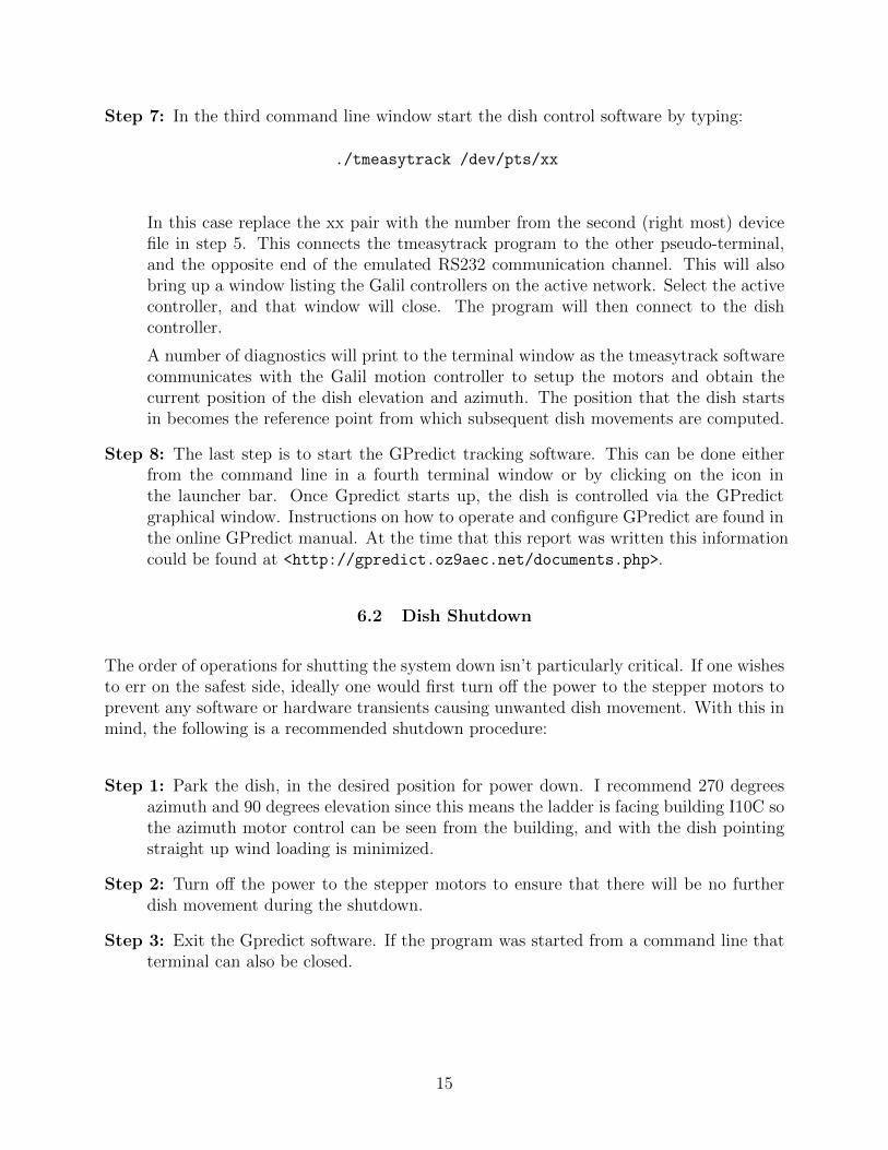
Step 7: In the third command line window start the dish control software by typing:
./tmeasytrack /dev/pts/xx
In this case replace the xx pair with the number from the second (right most) device file in step 5. This connects the tmeasytrack program to the other pseudo-terminal, and the opposite end of the emulated RS232 communication channel. This will also bring up a window listing the Galil controllers on the active network. Select the active controller, and that window will close. The program will then connect to the dish controller.
A number of diagnostics will print to the terminal window as the tmeasytrack software communicates with the Galil motion controller to setup the motors and obtain the current position of the dish elevation and azimuth. The position that the dish starts in becomes the reference point from which subsequent dish movements are computed.
Step 8: The last step is to start the GPredict tracking software. This can be done either from the command line in a fourth terminal window or by clicking on the icon in the launcher bar. Once Gpredict starts up, the dish is controlled via the GPredict graphical window. Instructions on how to operate and configure GPredict are found in the online GPredict manual. At the time that this report was written this information could be found at <http://gpredict.oz9aec.net/documents.php>.
6.2 Dish Shutdown
The order of operations for shutting the system down isn’t particularly critical. If one wishes to err on the safest side, ideally one would first turn off the power to the stepper motors to prevent any software or hardware transients causing unwanted dish movement. With this in mind, the following is a recommended shutdown procedure:
Step 1: Park the dish, in the desired position for power down. I recommend 270 degrees azimuth and 90 degrees elevation since this means the ladder is facing building I10C so the azimuth motor control can be seen from the building, and with the dish pointing straight up wind loading is minimized.
Step 2: Turn off the power to the stepper motors to ensure that there will be no further dish movement during the shutdown.
Step 3: Exit the Gpredict software. If the program was started from a command line that terminal can also be closed.
15

Step 4: Kill the remaining programs (tmeasytrack, tty0tty, and rotctld) by typing
ctrl-C
in the terminals used to start them. You can close the terminals too since they are no longer in use.
Step 4: Turn off power to Motion Controller in the antenna base pedestal.
Step 5: Attach the cables or ropes used to prevent the dish from being pushed around by the wind, and close and lock the hatchways.
16

7 SUMMARY
Automation of the dish antenna has been successful, and makes the system much more useful. For example, we can now track satellites as long as their ground track doesn’t exceed the system limitations described in Section 5. The motor control also makes pointing the dish much easier than hand cranking it to a new position.
Nevertheless, there are a number of things that we can do to improve this system. Work is underway to move more of the control system and measurement instruments into the upper structure of the dish. Equipment located in the upper structure moves with the antenna, so locating more of the electronics there means that fewer cables pass through moving parts of the antenna where they risk damage due to wrapping, pulling, twisting, and flexing. Work also continues into characterizing the dish’s overall performance. This includes verification of the pointing calibration, antenna gain, dish figure, surface accuracy, and focal point. The dish structure is also in need of refinishing and painting.
17

Figure 2: Block diagram of the control system.
Figure 3: Motion control equipment rack.
18

Figure 4: Azimuthal drive motor and gear box.
Figure 5: Azimuthal axis optical encoder.
19

Figure 6: Galil DMC-4123 motion control computer.
Figure 7: Wiring breakout board.
20

Figure 8: Cable connecting the breakout panel to the motor indexer plug.
Figure 9: Wiring between the motor amplifier and the equipment rack connector.
21
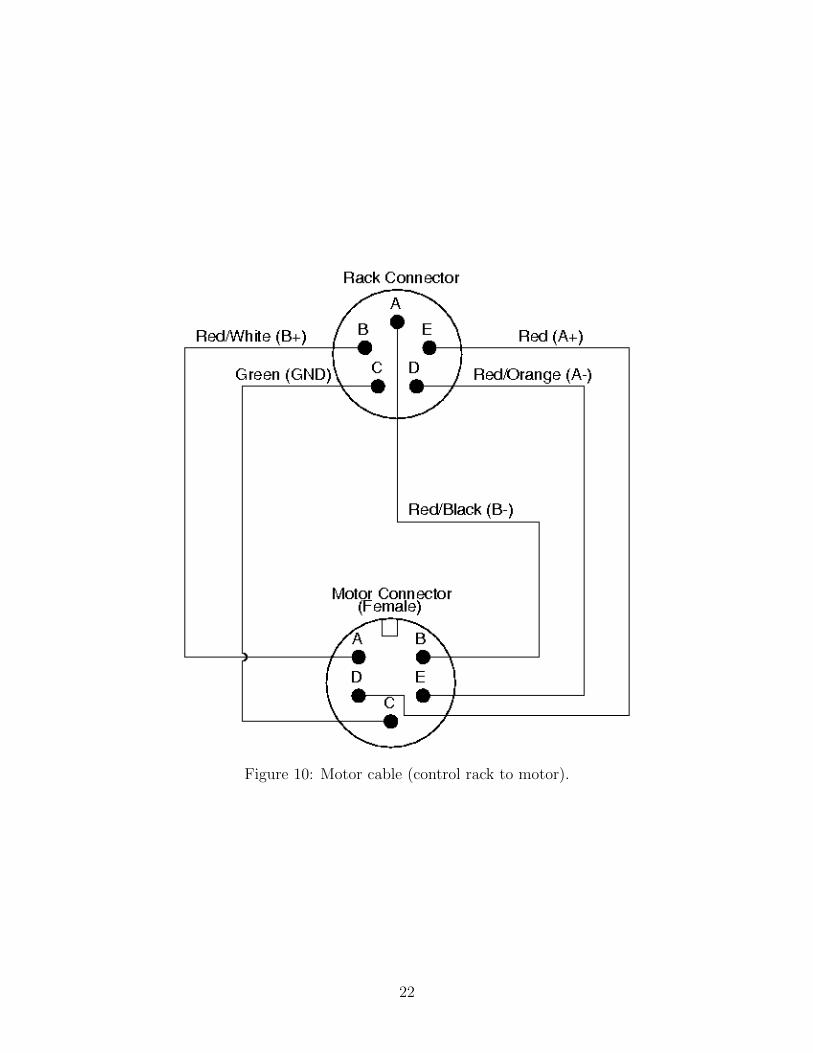
Figure 10: Motor cable (control rack to motor).
22

Figure 11: Encoder wiring between the break out panel and the equipment rack connector.
23

Figure 12: Plot of encoder count data versus elevation and azimuth angles in degrees.
24

Position 1
Position 2
After crossing the zero degreeazimuth point
the dish has to rotate clockwiseto avoid cable wrap.
North
East
South
West
Sat
ellit
e Pa
th
(90°)(270°)
(0°)
(180°)
Figure 13: Diagram of satellite tracking crossing the cable wrap limit.
sin(θ)
Azimuth rotation 1.23 Degrees
Distance the trackedobject movesin one second.
Objec
t Ran
ge
Figure 14: Dish rotation and tangential object track.
25

Form NTIA-29 U.S. Department of Commerce
(6/04) National Telecommunications and Information Administration
BIBLIOGRAPHIC DATA SHEET
1. Publication Number
TM-18-531 2. Government Accession Number 3. Recipient’s Accession Number
4. Title and Subtitle
The Dish Antenna at the Table Mountain I10C Site 5. Publication Date
February 2018 6. Performing Organization Code
NTIA/ITS 7. Author(s)
J. Wayde Allen 9. Project/Task/Work Unit No.
3156011-300 8. Performing Organization Name and Address
NTIA/ITS.M U.S. Department of Commerce 325 Broadway Boulder, CO 80305
10. Contract/Grant Number
11. Sponsoring Organization Name and Address
Table Mountain Modernization Project Institute for Telecommunication Sciences National Telecommunications & Information Administration U.S. Department of Commerce 325 Broadway Boulder, CO 80305
12. Type of Report and Period
Covered
14. Supplementary Notes
15. ABSTRACT (A 200-word or less factual summary of most significant information. If document includes a significant bibliography
or literature survey, mention it here.)
This paper describes the design and retrofit of the 3.7 meter (12-foot) dish antenna located near building I10C at the U.S. Department of Commerce Table Mountain Field Site and Radio Quiet Zone. 16. Key Words (Alphabetical order, separated by semicolons)
dish antenna; radio; RF; Table Mountain 17. Availability Statement
X Unlimited
For Official Distribution
18. Security Class (This report) 20. Number of Pages
17 19. Security Class (This page) 21. Price