;;,j /l' .-r-'lr-recf 'i joy ~.-,,7 -¥-'• .,/ /'~...
TRANSCRIPT

'I ;;,J /l' .-r- 'lr-recf /r> Joy ~.-,,7 -¥- '• .,/ /'~ ufc
{.///-'"- .,-/ Pic./ ./,?;,ctfru--'" /;,dCcc7.,- </ /1,
)-1; ( J d e/ /!. /lor/Je r',;•fr,n,e / c,/ !, J, lt'urd /

....:... r--....
::: .... ~~ ,....,~ 0: ~ ~ "",..; 1 1'\! (;- :-iS"}..
-,-, . -:.E oN ~ w•bi ~ . - -
r-: t . /2? ~ ~ 1 Y 11 6 ---------------------------
~NELASTI~INSTABTLI1I.JU:SU\R.CR.=:A!_LEHIG.H:JJNITERSI_TT=--_-__ -__ -__ -__ -_-__ -_____ ·,..
I L. W. Lu. Department of Civil Engineering, Lehigh University
iz. Y. She.n ' Department of Structures, Tong-Ji University
X. R. Hu. Research Institute of Structural Theory, Tong-Ji University
FRITZ ENGtN2:ERING LABORATORY LIBRARY
::.. ·- - ~ -
[ ':~-·"'- t. c...S. !, .. ~~=~=·~------------------------------------------------1 Results of research on inelastic instability of initially crooked ·-- -;;:, ~::~~c-- ~: columns and beam-columns are presented. The problems studied are:
i flexural instability of wide-flange columns and beam-columns, flex' :ural-torsional instability of concentrically and eccentrically loaded !single-angle columns, and flexural-torsional instability of H columns ' subjected to axial force and major-axis bending. Solutions to these
I problems have been obtained using two separate computer programs, one
, for flexural instability and the other for flexural-torsional insta- . ' bility. The latter is based on a new finite element procedure. For I .
each problem, typical results are given and the influence of the variables involved is discussed.
I
~ , No-tation
lA ·E I . I
e.
IK I L
IM I .Mp p
Py R
r
' S
, E:
. cross-sectional area
modulus of elasticity
load eccentricity
effective length factor
length of column
bending moment
plastic moment
axial load
axial yie~d load
rotational stiffness of end restraint
radius of gyration
section modulus
initial crookedness in x direction
initial crookedness in y direction
end moment ratio
non-dimensional eccentricity
..

t:.~~~NE cF 2u~,...; ~~G - H&\}
·".""'"l<E' oN Tl:><l wo !)T ~ ~
yield stress
In:tJtodu.c.tion
Researchers of steel structures at Lehigh University have enjoyed more than thirty years of continuous cooperation and exchange of information with Professor Michael R. Horne, the man being honored by this conference. The relationship began in the late 1940's when Professor Horne was at Cambridge University working on plasticdesign research with Lord John F. Baker. Much of the Lehigh research on plastic design and structural stability, including those of thewriters have benefitted greatly from the association with Professor Horne, and this paper is prepared as an expression of appreciation to him.
The paper deals with inelastic instability of columns and beam-col-! umns ,___a_s_uj)j_e_c_t__t.o..___whic.h.__Er_o.£.es.sJl.r....JioJ:n.e_has_made d i s tin guishe.u....--. contributions. Among the topics selected for presentation, two are l flexural instability columns:
1. axially loaded columns with initial crookedness and end restraint
2. initially crooked beam-columns ;and three are spatial instability problems involving lateral and torsional deformations:
3. axially loaded single-angle columns with initial crookedness
4. initially -crooked single-angle columns loaded through gusset plates
5. beam-columns with minor-axis crookedness and subjected to major-axis bending.
The results have been obt~ined from two computer programs developed recently at Lehigh for instability analysis of thin-walled structural
,members. One of the programs is for members with planar deformation only. The other program considers the effect of spatial deformations and can take into account the secondary bending and torsionalmoments caused by these deformations. The method of analysis developed for the planar problem is discussed first.
1. PLANAR STABILITY ANALYSIS A general method of analysis, which can include almost all the known factors affecting the behavior of beam-columns, has been developed. It is similar to the method used previously in analyzing laterally loaded columns by Lu and Kamalvand (1). A description of the present method as applied to axially loaded columns has been presented by Shen and Lu (2). The specific factors that have been included in the development are: 1. initial crookedness, 2. end restraint, 3. eccentricities of axial load, 4. end-moment ratio, 5. residual stresses, 6. variation in mechanical properties of material over cross section,
' 7. stress-strain characteristics of material, and 8. loading, unloading and reloading of yielded fibers. For the case of a beam-column, it is possible to perform precise analysis for three possible loading paths: proportionally increasing axial load and bending moment, constant axial load and increasing bending moment, and constant bending
1moment and increasing axial load. The method makes no assumption
:.. .- • - .. ~ r - •.
. "' ., .... ~

...<- '-E o= RVN"-'•"1£>- n51'1J, . ·, -.o .: oN j1;>('T w ol)i>, ~ -,-------------L------------
['1\'ftn regar.cC.t:_~_fhLsha.:P-"e ~o_f___Th.e infr.Ial.lio_Qk_edii_ess- or -of 1:J1e -d~-- - -[..._ ~~ :-::, ·--=c."
I fleeted column under load. The analysis gives both the ascending r ~,- ~ , .c : <
I and descending branches of the load-deflection curve. -~ -~ '
,2. FLEXURAL INSTABILITY OF COLUMNS 1Much of the research conducted on · columns in the 1950's and early 1960's placed emphasis on residual stresses and their effect on the tangent modulus load of perfectly straight columns. The tangent modulus load, which is only slightly less than the maximum or ul timate load, was subsequently accepted as a suitable basis for evaluating column strength. Since most of practical columns are initially
1crooked, the phenomenon of buckling or bifurcation at the tangent •modulus load could not occur and failure is usually due to instability. Work on the effect of initial crookedness has been carried out,
. and the results show that for some columns the reduction in strength is too significant to be ignored in a rational design procedure.
lxh.e earlier research on_c.olumn sttength a]so_sh.o.ws that the...magnit.ude , Jof residual stresses in rolled shapes is approximately the same for , steels of different yield stresses. For light column shapes made of
: structural carbon steel (oy = 36 ~~), the maximum compressive re-I sidual stress occurs at the flange tips and is about 0. 3 au ( 10. 8 _ ;, ,~ _{_), iThis value of residual stress has also been found in shape~ of high !strength steels.
!Figure 1 shows the ultimate strength of the W8 x 31 columns made of . steels with yield stresses of 36, 50 and 100 ksi and bent about its minor axis. The flange tip residual stress has been kept constant
lat 10.8 ksi. The non-dimensional slenderness ratio A is defined by
I A=-7 ~ L I rr JE r (1)
I 1 The 100 ksi column is least affected by residual stresses and is the ' strongest. The initial crookedness for all the cases is assumed to !follow a sine curve with a maximum value of u0m = 0.001L, which is the maximum acceptable sweep of the U.S. mill practice. It is seen
lthat the initial crookedness has its maximum effect for A between 1.05 and 1.2. For the 36 ksi column the maximum reduction is 31%.
!Another factor important in column design is end restraint, which tends to increase the carrying capacity of col umns. The exact amount of restraint that exist at the ends of a column in a practical structure is difficult to evaluate, but limited information is available for columns in building frames utilizing "simple" connections. Design recommendations for such columns have been presented by Lui and Chen (3). Figure 2 shows the effect of a small end restraint on the strength of the columns given in Fig. 1. The rotational stiffness R of the restraint is equal to 0.2EI / L a t both ends. Ther e is a noticeable increase in strength, even for such a small end restraint. It has been found by Shen and Lu (2) that the restraint
!required to produce an increase in strength which is exactly equal I to the reduction caused by a given crookedness varies with A. For , the 36 ksi column, the maximum required R is 2.45E1/L for u0m = 0.007L occurring at A= 1.2.
; ... .. l ....;, •

-'-' _,,... : CF u~,..; IN.(;- J,St\} .
~ ..; . E o"' =<~ ...,. !) 11 --
r r FlEXUR!r__Ili~MEC_QlUMNS-- - - - - - - - - - --- - - -I . . . -·- ... ·
;::::.r;.
Analytical studies have also been made on initially crooked beam-columns which fail by in-plane flexural instability. Figure 3 gives the axial load vs. end moment (P-M) interaction curves for the case of symmetrical single curvature bending (end moment ratioS= 1.0). The solid curves are for crooked W8 x 31 columns Coy = 36 ~i) with u0m = 0.001L. The dashed curves are for initially straight columns and are the basis of some current-ly available design formulas. The difference between the solid and dashed curves for a given slenderness ratio becomes significant when the axial load is high. Figure 4 shows comparisons between the P-M interaction curves of the straight W8 x 31 columns and those of the equivalent H columns welded from milled plates. The current formulas are likely to give very unconservative estimate of the strength of welded columns. A detailed discussion of the results obtained on crooked beam-columns can be found in a forthcoming report by Shen and Lu (4).
4. SPATIAL INSTABILITY ANALYSIS A finite element method has been developed for instability analysis of initially crooked members with spatial deformations. Such a member would usually fail by flexural-torsional instability. The method and the computer program developed are very general and can be used to analyze axially loaded columns, beams and beam-columns
, with any type of rotational and torsional restraints. Applications have already been made to such problems as single angle columns with concentric and eccentric axial load, segmented beams subjected to transverse load, columns under combined axial load and torsion, H section beam-columns subjected to major axis bending, and biaxially loaded beam-columns. A description of the method has been given by ' Hu, Shen and Lu (5). The results of some of these studies are presented below.
5. FLEXURAL-TORSIONAL INSTABILITY OF SINGLE-ANGLE COLUMNS A single-angle column with initial crookedness (or camber) and subjected to a concentric axial load would fail by flexural-torsional instability. The ultimate strength of such a member depends on the crookedness, residual stress, end restraint, and geometrical properties of cross section. The U.S. mill practice permits a maximum camber of L/480 for structural size angles and L/240 for bar size angles.
Numerical calculations have been carried out on four selected angle 'columns made of 36 ksi material. Two of these are structural size angles, L 125 x 125 x lOmm and L 125 x 80 x lOmm, and the other two are bar size angles,L2 x 2 x 1/4 andL3 x 2 x 1/4 (this section normall~ qualifies as structural size). The columns are simply supported ln both bending and torsion. Figure 5 shows the ultimate strength of the columns as a function of the slenderness ratio A (note: rmin is used in determining A). The camber u is assumed to be in the negative direction of the x axis. For unegual leg angles this represents the most critical situation. The effect of residual stresses has been taken into account in the calculations. The results show that the amount ofcamber has a significant influence on the strength of the angles when A is less than about 1.5. Also, the
..
-~: .-

!.- .:. - _......, = ~ a ... · "-~,..; '1\!6 - ,,&"}
=_-..""<.£ e>N ~ w•!)T-. -- ~--------·--..L------------
un-eq-ual - leg - angres are wea"Ker tnan -tnEC.e_ql.ta.T__l_eLangl.e.:LRlilL.ih -"'--same camber.
6. SINGLE-ANGLE COLUMNS LOAVEV THROUGH GUSSET PLATES
Angles are often used as secondary members in main structures and connection is usually made through gusset plates. The load transnitted by the gusset plate acts eccentrically on the angle and causes biaxial bending. The strength of an eccentrically loaded angle can be determined by a flexural-torsional in~tability analysis. For an unequal leg angle, it is generally believed that the member can carry more load if the connection is made through the short leg. This problem has been examined recently as part of a general study on angle columns, and some of the results are shown in Figs. 6 and 7. The shape selected is L 3 x 2 x 1/4 and the thickness of the gusset is 0.424" (this is to simulate the test specimens used in previous studies). The angle is so oriented that the X axis is parallel to the gusset. The camber is assumed to be in the positive direction -o£-th"e-y-ax:ts-crtrtlllcrs-altlax~mum value of L/2"4--o at tne m~a=ne~gnt. 'The direction of the camber is again selected to correspond to the most critic'al situation. The angles are rotationally restrained at the ends in both the X and y directions. The stiffnesses of the end Testraints have been so selected that, if the angles were perfectly ,straight and concentrically loaded, the effective buckling length would be equal to 0.8L, 0.9L and l.OL for the three cases studied.
The results of Fig. 6 are for the case where the long leg is the outstanding leg, while in Fig. 7 the, short leg is the outstanding leg. A comparison of the results shows that the "long leg outstanding" arrangement is not always the more favorable arrangement. In fact, higher ultimate loads may be obtained with the "short leg outstanding" arrangement for relatively short members (A< 7.2 forK= 0.8). The results also indicate that end restraint can significantly increase the strength of an eccentrically loaded single-angle column.
7. FLEXURAL-TORSIONAL INSTABILITY OF BEAM-COLUMNS
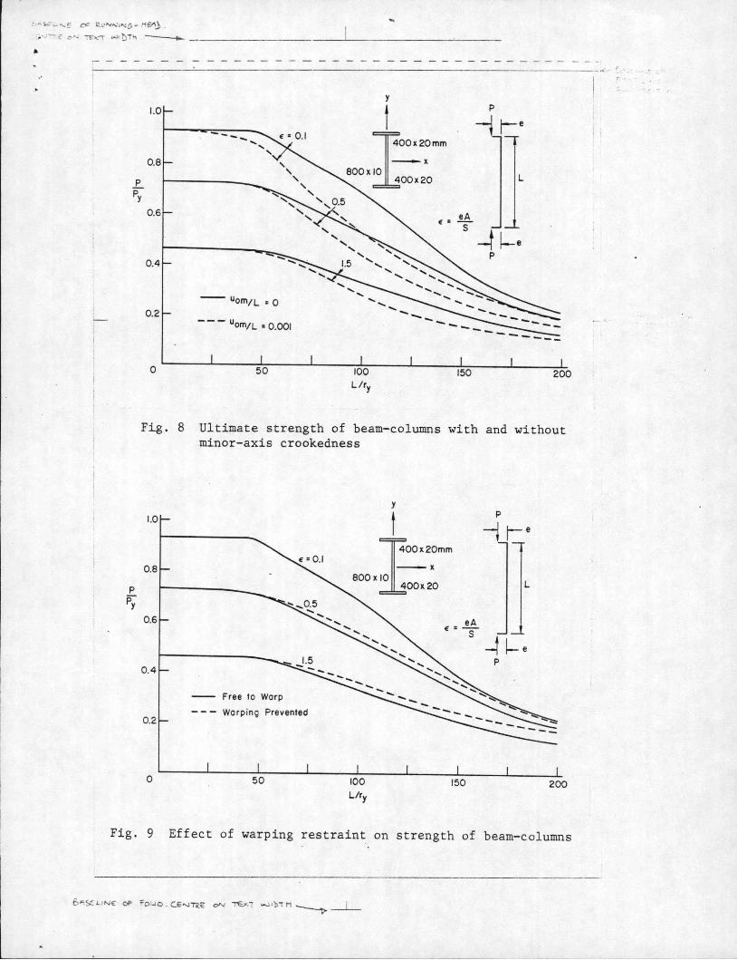
When an initially straight H column is subjected to simultaneously applied axial load and major-axis bending moment, flexural-torsional buckling may take place at a critical combination of the axial load and bending moment. Further increase of the applied load is possible until the member finally fails by instability. A post-buckling instability analysis is therefore required to determine the ultimate strength of such a member. However, if the member is initially crooked about the minor axis, spatial deformations usually take place as soon as the load is applied and failure occurs when the instability limit is reached. A study of the effect of initial crookedness on the strength of beam-columns subjected to major-axis bending has recently been completed, and Fig. 8 shows some of the results. The load P is applied eccentrically with an eccentricity e. The column is a built-up member with a flange width of 400mm and a web depth of 800mm. The bending moment Pe is applied about the x axis. For the purpose of comparison of similar results obtained for other columns, a non-dimensional parameter E = eA/S is used to specify the load eccentricity, where A is. the cross sectional area and S is the section modulus for bending about the x axis. The initial crookedness at the midheight is Uom = O.OOJL.

t. .. q:.;; :...l'\,;e cF ~ 1.-' "'" 1 "-~£; - J-t SJ'\} .
CN1":'t€ oN~ W1't)i 11 -------........ - -------------'-------------
l.he r_e.--:-~til ts -sliQ__w- iliat~Jie- infi_i-aLci.oofe_a-ness nas -a -ve__iY -sll_bst-::-a_nt_:l"al~:._- r-
,effect on the strength of the columns, especially for the case of -small E. This fact is not recognized in most of the current design procedures for laterally unbraced beam-columns.
The results presented in Fig. 8 are for the so-called "warping free" condition at the ends. The strength of the columns may be increased somewhat, if warping deformation is assumed to be fully prevented, as illustrated in Fig. 9.
8. SUMMARY AND CONCLUSIONS five studies of inelastic instability failure of columns and beamlcolumns have been described. The results presented indicate that
1. Initial crookedness and end restraint are two important factors affecting the strength of axially load columns failing by flexural instability and should be rationally dealt with in column design
~aLCXQ__Qk_e_dn_e_s__s_a_l_s__o__af_f_e_c___t_s___the_s___t__r_e_ng_t_h___o___f_b_e_am::_col::_ .
umns and, for the same c.rookedness, the -strength difference b"etween rolled and welded members is very significant
3. Unequal leg angles are not as strong as equal leg angles when they are subjected to concentric axial compression
4. When an unequal leg angle is loaded through gusset plates, the "long leg outstanding" arrangement does not always give higher ultimate load
5. When a laterally unbraced H column is subjected to combined axial load and major-axis bending, its ultimate strength is substantially reduced by initial crookedness about the minor axis.
R e. 6 eJLe.n.c.e-6
1. Lu, L.W. and Kamalvand H. 'Ultimate strength of laterally loaded columns.' Journal of Structural Division, ASCE, Vol. 94, No. ST6, 1968.
2. Shen, Z.Y. and Lu, L.W. 'Analysis of initially crooked, end restrained steel columns.' Journal of Constructional Steel Research, Vol. 3, No. 1, 1983.
3. Lui, E.M. and Chen, W.F. 'End restraint and column design using LRFD.' Engineering Journal, AISC, Vol. 20, No. 1, 1983.
4. Shen, Z.Y. and Lu, L.W. 'Strength of initially crooked beam-columns.' Fritz Laboratory Report 471.7, Lehigh University (in preparation).
5. Hu, X.R., Shen, Z.Y. and Lu, L.W. 'Inelastic stability analysis of biaxially loaded beam-columns by the finite element method.' Vol. 2, Proceedings of the International Conference on Finite Element Methods, Shanghai, China, 1982.
, ': .. ~ c ... ::.

· ":_So"'-'"-E CY" R~"'"' '"'6- Hs-->_1 .
·,.- .:"TTe oN~ ""'l:::>ir~ .- -------------'-------------
,--- ----'------------------=-----:--===~-::---:-::=-::----------...("- 6""i"L.-'".)'"' cF
Ft~.._.:- ~ ' ' .Jt r..
0
ksi
36 50 100
Uom/L
0.001 0.001 0.001
---- 36 0 ----50 0 ----100 0
0.5
W8 X 31
y axis
1.0 1.5
Fig. 1 · uJ;timate ~t:re,ngth of straight and cr.ooked columns
cr cry
oy R
ksi
36 0 - 50 0 WSx 31 - 100 0 y axis
36 0.2 EI/L u0 m/L = 0 .001 ---·- 50 -~~- 100
0 0.5 1.0 1.5
Fig. 2 Effect of end restraint on strength of crooked columns
I . s. -1 «- '.,.,
~ ...... , ....
I I

. s.;--··E 0"" I<•' "'"' 'NG- li&\_b .
·.-,{oN TI'><T w •!:>T fl ---..,.. -'-- --------- - - -L----- - ----- - -
0
Fig. 3
y AliS {3 • 1.0
"om/L • 0
- Rolled WF Uom/L •0
p Py
0 .2 0.4 0.6 0 0.2 0.4 0 .6 0 .8
Mf Mp M/Mp
Interaction curves for Fig. 4 Interaction curves straight and crooked rolled and welded beam-columns beam-columns
L 125 x 125 x IOmm } Uo = __ 1 _ r---- l 125 X 80 x 10 L 480
0
l 2 X 2 X l;4 } Uo = __ I_ L3 X 2 X 1;4 L 240
2 3
Fig. 5 Ultimate strength of concentrically loaded single-angle columns ·
..
1.0
for

~.~:. ,.... l...;f'o..JE OC R. t.• N.....: t"lC, - l-iSt\} .
-. ,' T:"'E oN ~ w >t:>Tk --
;- - --- ---------------------------------------------------------------------------- ~~: - ~.·.
0
', ..r Concentrically ~ Loaded
' \ \
\ \
\ \
\ \ ,.
ex=0.507"
ey~-1 . 205"
\
L3 X 2 X lt4
0.424" Thick Gusset
Vo/L = 1t24a
y
b, _l''
Fig ~ 6 Ultimate strength of single-angle columns loaded through gusset plates, long let outstanding
0
', Concentrically ' Loaded
',/ \
\ \ ~
ey = -0.705"
L3 X 2 X 1!4
0.424" Thick Gusset
VaiL= 1/240
2 3
Fig. ~ 7 Ultimate strength of single-angle columns loaded through gusset plates, short leg outstanding
· .... -- "-E o= R.t.'""'" ti'\! G - tiEl\} .
.. • · ·-£ o'- ~-. w•!:l ., -
y
t p
-i [-e --- I00•20mm -x
800x l p 00x20
Py
E : ~ s -t ~e p
-- Uom;L • 0
--- Uomtl • 0.001
0
Fig. 8 Ultimate strength of beam-columns with and without minor-axis crookedness
p
Py
0
Free to Warp
Warping Prevented
l
Fig. 9 Effect of warping restraint on strength of beam-columns
r .