iwc73a2 - mil-std-188everyspec.com/mil-specs/mil-specs-mil-b/download... · distribution statement...
TRANSCRIPT
I NOT MEASUREMENT j
I SENSITIVE 1!
MIL-B-22342D26 Mav 1989SUPERSEDINGMIL-B-22342C24 March 1981
MILITARY SPECIFICATION
BROWS, ALUMINUM, BEAM AND TRUSS
This specification is approved for use by all Departmentsand Agencies of the Department of Defense.
1. SCOPE
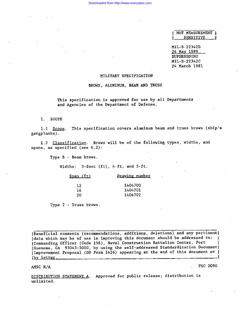
1.1 Scoue. This specification covers aluminum beam and truss brows (ship’sgangplanks).
1.2 Classification. Brows will be of the following types, widths, andspans, as specified (see 6.2):
Type B - Beam brows.
Widths: 3-foot (ft), 4-ft, and 5-ft.
SDan (ft) Drawinp number
12 140470016 140470120 1404702
Type T - Truss brows.
lBeneficial comments (recommendations, additions, deletions) and any pertinent[Idata which may be of use in improving this document should be addressed to: IlCommanding Officer (Code 156), Naval Construction Battalion Center, Port IlHueneme, CA 93043-5000, by using the self-addressed Standardization Document~lImprovement Proposal (DD Form 1426) appearing at the end of this document or ]Ibv letter. I
AMSC N\A FSC 2090
DISTRIBUTION STATEMENT A. Approved for public release; distribution isunlimited.
Downloaded from http://www.everyspec.com

MIL-B-22342D
Span 3-ft width 4-ft widthm Drawin~ number Drawinr number
25 1404703 140470330 1404703 140470335 1404704 140470440 1404705 140470550 1404706 140470660 1404707 140470770 1404708 14047088090
5-ft widthDrawin~ number
140470314047031404704140470514047061404707140470814047091404710
1.2.1 Part or identifvin~ numbers (PINs). The specification number, type,width and span combined to form the specification PINs for the brows covered bythis specification (see 6.5). The PINs for the brows are established as fol-lows :
M22342-~-U-z1111
Specification number 1111Type code number (see 6.5) IIIWidth code number (see 6.5) IISpan code number (see 6.5) I
2. APPLICABLE DOCUMENTS
2.1 Government documents.
2 . 1 . 1 Specifications. standards. and drawings. The following specifica-tions, standards, and drawings form a part of this specification to the extentspecified herein. Unless otherwise specified, the issues of these documentsare those listed in the issue of the Department of Defense Index of Specifica-tions and Standards (DODISS) and supplement thereto, cited in the solicitation.
SPECIFICATIONS
COMMERCIAL ITEM DESCRIPTIONS
A-A-880 - Strapping, Steel, Flat and Seals.
FEDERAL
T-T-616 -PPP-B-601 -PPP-B-621 -PPP-B-636 -
MILITARY
MIL-P-116MIL-P-5431
Treatment: Mildew Resistant, for Rope and Cord.Boxes, Wood, Cleated-Plyood.Boxes, Wood, Nailed and Lock Corner.Boxes, Shipping, Fiberboard.
Preservation, Methods of.Plastic Phenolic, Graphited, Sheets, Rods, Tubesand Shapes.
2
Downloaded from http://www.everyspec.com

MIL-B-22342D
MIL-P-15035 -
MIL-P-23469 -
STANDARDS
MILITARY
MIL-STD-129 -
DRAWINGS
Plastic Sheet: Laminated, Thermosetting,Cotton-Fabric-Base, Phenolic-Resin.Pins and Collars, Swage-Locking (Lockspins)General Specification for.
Marking for Shipment and Storage.
NAVAL FACILITIES ENGINEERING COMMAND
1404695 - Beau and Truss Brows - Notes and Details.1404696 - Beam and Truss Brows - Details and Fittings.1404697 - Beam and Truss Brows - Sections ‘and Details.1404698 -1404699 -1404700 -1404701 -1404702 -1404703 -1404704 -1404705 -1404706 -1404707 -1404708 -1404709 -1404710 -1404711 -1404712 -
Truss Brows -Truss Brows -Aluminum BeamAluminum BeamAluminum BeamTruss Brows -Truss Brows -Truss Brows -Truss Brows -Truss Brows -Truss Brows -Truss Brows -Truss Brows -Truss Brows -Truss Brows -
Welding Notes and Details.Member Forces.Brows - 3-12: 4-12: 5-12.Brows - 3-16: 4-16: 5-16.Brows - 3-20: 4-20: 5-20.3-25 & 30; 4-25 & 30: 5-25 & 30.3-35: 4-35: 5-35.3-40: 4-40: 5-40.3-50: 4-50: 5-50.3-60: 4-60: 5-60.3-70: 4-70: 5-70.5-80.5-90.5-90 Notes and Details.5-90 Welding Notes and Details.
(Unless otherwise indicated, copies of federal and military specifications,standards, and handbooks are available from the Naval Publications and FormsCenter, (ATTN: NPODS), 5801 Tabor Avenue, Philadelphia, PA 19120-5099.)
(Copies of specifications, standards, drawings, publications, and otherGovernment documents required by contractors in connection with specificacquisition functions should be obtained from the contracting activity or asdirected by the contracting activity.)
2.2 Non-Government publications. The following documents form a part ofthis specification to the extent specified herein. Unless otherwise specified,the issues of the documents which are DoD adopted are those listed in the issueof the DODISS cited in the solicitation. Unless otherwiseof the documents not listed in the DODISS are the issue ofare current on the date of the solicitation.
AMERICAN NATIONAL STANDARDS INSTITUTE, INC. (ANSI)
specified, the issuesthe documents which
ANSI B1.1 - Screw Threads (UN and UNR Thread Form) Unified Inch.
3
Downloaded from http://www.everyspec.com

(Application forStandards Institute,
AMERICAN SOCIETY
MIL-B-22342D
copies should be addressed to the American NationalInc. , 1430 Broadway, New York, NY 10018.)
FOR TESTING AND MATERIALS (ASTM)
ASTM A 242 - High-Strength Low Alloy Structural Steel.ASTM A 325 - High-Strength Bolts for Structural Steel Joints,
Including Suitable Nuts and Plain Hardened Washers.ASTM A 473 - Stainless and Heat Resisting Steel Forgings.ASTM A 502 - Steel Structural Rivets.ASTM B 209 - Aluminum and Aluminum-Alloy Sheet and Plate.ASTM B 210 - Aluminum-Alloy Drawn Seamless Tubes.ASTM B 211 - Aluminum-Alloy Bar, Rod and Wire.ASTM B 221 - Aluminum and Aluminum-Alloy Extruded Bars, Rods, Wire,
Shapes and Tubes.
(Application for copies should be addressed to the American Society forTesting and Materials, 1916 Race Street, Philadelphia, pA 19103.)
NATIONAL FIRE PROTECTION ASSOCIATION (NFPA)
NFPA 70 - National Electrical Code.
(Application for copies should be addressed to the National Fire ProtectionAssociation, Battery March Park, Quincy, MA 02269.)
900
550
the
THE ALUMINUM ASSOCIATION
Aluminum Construction Manual, Section 5.
(Application for copies should be addressed to the Aluminum Association,- 19th St. N.W., Washington, D.C. 20006.
AMERICAN WELDING SOCIETY, INC. (AWS)
AWS D1.2 - Structural Welding Code, Aluminum
(Application for copies should be addressed to the American Welding Society,N.W. LeJeune Rd., P.O. Box 351040, Miami, FL 33135.)
(Non-Government standards and other publications are normally available fromorganizations which prepare or that distribute the documents. These docu-
ments also may be available-in or through libraries or other informationalservices.)
2 . 3 Order of precedence. In the event of a conflict between the text ofthis specification and the references cited herein (except for associated detailspecifications, specification sheets or MS standards), the text of this specifi-cation shall take precedence. Nothing in this specification, however, shallsupersede applicable laws and regulations unless a specific exemption has beenobtained.
4
Downloaded from http://www.everyspec.com

MIL-B-22342D
3. REQUIREMENTS
3 . 1 S t a n d a r d c omm e r c i a l D r o d u c t . T h e brows shall, as a minimum, be inaccordance with the requirements of this specification and shall be the manu-facturer’s standard commercial product. Additional or better features whichare not specifically prohibited by this specification but which are a part ofthe manufacturer’s standard commercial product, shall be included in the browsbeing furnished. A standard commercial product is a product which has beensold, or is being currently offered for sale on the commercial market throughadvertisements or manufacturers’ catalogs, or brochures, and represents thelatest production model.
3.2 First article. When specified in the contract or purchase order,a sample shall be subjected to first article inspection (see 4.2.1, 6.2 and6.4.)
3 . 3 I n t e r c h a n z e a b i l i t v . A l l units of the same classification furnishedwith similar options under a specific contract shall be identical to theextent necessary to ensure interchangeability of component parts, assemblies,accessories, and spare parts.
3 . 4 Drawin~s. The drawings forming a part of this specification areengineering design drawings. The contractor is responsible for preparing theirown shop drawings. Where tolerances prescribed may cumulatively result inincorrect fits, the contractor shall provide tolerances within those prescribedon the drawings to ensure correct fit, assembly and operation of the items. Nodeviation from the prescribed dimensions or tolerances is permissible withoutprior approval of the contracting officer.
3.5 Materials. Materials used shall be free from defects which wouldadversely affect the performance or maintainability of individual components orof the overall assembly. Materials not specified herein shall be of the samequality used for the intended purpose in commercial practice. Unless otherwisespecified herein, all equipment, material, and articles incorporated in the workcovered by this specification are to be new and fabricated using materialsproduced from recovered materials to the maximum extent possible withoutjeopardizing the intended use. The term “recovered materials” means materialswhich have been collected or recovered from solid waste and reprocessed tobecome a source of raw materials, as opposed to virgin raw materials. Unlessotherwise specified, none of the above shall be interpreted to mean that the useof used or rebuilt products are allowed under this specification.
3.5.1 Aluminum. Unless otherwise specified herein or on the drawings,plates, structural shapes, forgings, bolts, nuts, washers, rivets, pipe,stanchions, hangers, and fittings shall be fabricated from alloy 6061-T6 con;forming to ASTM B 209, ASTM B 210, or ASTM B 211; or alloy 6061-T6 orT6511 conforming to ASTM B 2 2 1 . When furnished, extruded floor gratings shallbe fabricated of alloy 6063-T6 conforming to ASTM B 221. At the option of thevendor, the aluminum alloy tube may be alloy 6063-T832. When specified (see6 . 2 ) , g u a r d r a i l s , p o s t s , and handrails shall be furnished with anodized finish.Floor plates, when furnished, shall be fabricated of alloy 5454 or alloy6061 conforming to ASTM B 209, ’and shall be of a temper and thickness adequateto sustain, without permanent deflection, the floor test loads indicated on
5
Downloaded from http://www.everyspec.com

I MIL-B-22342D
drawing 1404695. The plates shall be covered with a commercially availablenonslip deck coating consisting of a one-part binder combined with a nonskidgrid (see 6.8).
3.5.2 Steel. When furnished, ship connections of stainless steel, includ-ing plates, hooks, bolts, nuts, and washers shall be chromium-nickel steelconforming to ASTM A 473, type 302 or 303. ASTM A 242 structural steel, ASTMA 325 bolts, nuts, washers and ASTM A 502 rivets may be substituted for stain-less steel.
3.5.3 Svnthetic laminate. To reduce corrosion, galvanic action betweenmetals shall be prevented by separating dissimilar metals from each otherwith a non-conductor. Separation sheets l/16-inch thick shall be providedwhere indicated on the drawings and may be plastic sheet conforming toMIL-P-15035 (see 6.9).
3.6 Desire and construction. The design of the brows shall be as specifiedherein and as shown on the applicable drawings. When specified (see 6.2), trussbrows shall be furnished in sections not exceeding 32 ft in length. The methodof connecting the sections shall be the responsibility of the contractor. Allfield connections shall be designed to sustain design loading of brows.
3.6.1 Tme B. beam brows. Beam brows shall have aluminum pipe handrailsand floor plates except when specified (see 6.2), beam brows shall have ropehandrail and extruded aluminum floor grating, or any specified combination ofthese components.
3.6.2 Tme T. truss brows. Truss brows shall have aluminum pipe handrailsand extruded aluminum floor grating.
I3.6.3 Ship connections. Ship connections shall consist of bolted aluminum
angles and wear plates except when specified (see 6.2), stainless steel hooks inaccordance with drawing 104697 shall be provided for ship connections.
3.6.4 Rollers and caster wheels. Steel roller wheels shall be mounted onthe shore end of each brow except when specified (see 6.2), casters shall befurnished. Bearings, pipe, plates, housings, and caster horn assemblies shallbe heavy-duty type, capable of sustaining the combined dead load and floortest loads noted on drawing 1404695. Pipe rollers shall conform to the detailson drawing 1404696 corresponding to the loading of the brow for which designed.Caster wheels shall be a heavy-duty commercial product designed for dead loadplus live load plus safety factor, and having one or two wheels as indicated ondrawing 1404696 for corresponding brow loadings. Wheels shall be mounted withbearings.
3,6.5 Bearinzs. Bearings shall be oil-impregnated, self-lubricating, orpermanently lubricated synthetic resin construction. The rated load capacitiesof bearings shall be not less than the maximum combined dead and live testloads to be sustained by any individual roller or caster wheel, based on grossweights and design loadings indicated on the drawings. Bushing bearings forrollers shall be of graphite-impregnated plastic conforming to MIL-P-5431, orother low-frictional plastic, such as molybdenum disulfide filled nylon, suit-able for the use and loading conditions. Low frictional plastic pillow blocksmay be used when suitable.
6
Downloaded from http://www.everyspec.com

MIL-B-22342D
3 . 6 . 6 C l e a t s . C l e a t s s h a l l be in accordance with drawing 1404696.
3.6.7 Nuts and bolts. Nuts and bolts shall be of the size and quantityindicated on the drawings. The bolt heads and nuts shall be of the regularhexagon type. Bolts and nuts shall be aluminum-alloy conforming to 3.5.1,except where stainless steel is indicated on the drawings. Stainless steelshall conform to 3.5.2.
3 . 6 . 8 I t oD e . When rope handrails are provided on beam brows, they shall be3/4-inch polypropylene rope. Rope shall be treated for mildew resistance inaccordance with T-T-616.
3.6.9 Lizhtin~ eauiment. When lights are specified (see 6.2), the wiringconnections, accessories, and lamps shall be furnished and installed inaccordance with drawing 1404725 and the National Electrical Code for weather-proof installation. Alternate lighting equipment of equivalent performancemay be used when approved in advance by the contracting officer. Unlessotherwise specified (see 6.2), the receptacle and switch shall be located at theshore end of the brow.
3.7 Identification markin~. Identification shall be permanently andlegibly marked directly on the brows or on a corrosion-resisting metal platesecurely attached to the brows at the source of manufacture. Identificationshall include the manufacturer’s model and serial number, name and trademark tobe readily identifiable to the manufacturer.
3.8 Liftiruz attachments. Aluminum pad eyes and lifting eyes shall beprovided as detailed on the drawings.
3.9 Workmanship. The completed brows shall have a uniformly clean appear-ance, free from all fabrication and mill markings, smudges, and foreignmaterials. Handrails and all exposed surfaces and edges shall be smooth andfree from sharp projections.
3.9.1 Welding. Welding procedures shall be in accordance with a nationallyrecognized welding code. The surface of parts to be welded shall be free fromrust, scale, paint, grease, or other foreign matter. Welds shall be of suffi-cient size and shape to develop the full strength of the parts connected by thewelds. Welds shall transmit stress without permanent deformation or failurewhen theings.
“
3.9.:of weldsplatformutilizedoperatorwith the
parts connected by the weld are subjected to proof and senice load-
.1 Welder qualification. All welders shall be qualified for the typesand for the positions they are required to use in construction of the
Qualification shall be on the type of base material and fillerin actual construction or on similar alternate materials not requiringrequalification. Welder qualification shall be performed in accordanceapplicable sections of the AWS Standard Qualification procedure.
Copies of the qualification record for each qualified welder shall be.kept bythe manufacturer or contractor and shall be available to authorized Governmentinspectors. Aluminum shall not be flame cut, .and weldments shall conform to theAA Manual, as applicable.
7
Downloaded from http://www.everyspec.com

MIL-B-22342D
3.9.2 Bolted connections. Bolt holes shall be accurately punched ordrilled and shall have the burrs removed. Washers or lockwashers shall beprovided in accordance with good commercial practice, and all bolts, nuts,and screws shall be tight. Screw threads shall conform to ANSI B1.1.
3.9.3 Riveted aluminum connections. When riveting is specified (see 6.2),spacing and edge distance of rivets shall conform to The Aluminum Association,Aluminum Construction Manual, Section 5. Rivet holes shall be accuratelydrilled to a diameter not to exceed 104 percent for cold driven rivets or107 percent for hot driven rivets. The rivet holes shall be drilled whilethe structural members are clamped in their final position. Burrs and roughedges shall be removed. Heat shall not be applied in any manner which willaffect the temper of the structural aluminum. Rivet heads shall be of approvedshape, full, neatly made, concentric with the rivet holes, of uniform size forthe same diameter rivet, and in full contact with the surface of the member.Aluminum swage-locking pins and collars in accordance with-MIL-P-23469, withdiameter equal to rivet diameter are acceptable in lieu of rivets. In addition,buck bilting will be acceptable as an alternative to riveting.
3.9.4 Riveted steel connections. Rivet holes shall be accurately punchedor drilled and shall have the burrs removed. Rivets shall be driven withpressure tools and shall completely fill the holes. Rivet heads, when notcountersunk or flattened, shall be of approved shape and of uniform size for thesame diameter of rivet. Rivet heads shall be full, neatly made, concentric withthe rivet hole, and in full contact with the surface of the member.
4. QUALITY ASSURANCE PROVISIONS
4.1 ResDonsibilitv for inspection. Unless otherwise specified in thecontract or purchase order, the contractor is responsible for the performanceof all inspection requirements (examinations and tests) as specified herein.Except as otherwise specified in the contract or purchase order, the contractormay use his own or any other facilities suitable for the performance of inspec-tion requirements specified herein, unless disapproved by the Government. TheGovernment reserves the right to perform any of the inspections set forth in thespecification where such inspections are deemed necessary to ensure supplies andservices conform to prescribed requirements.
4.1.1 ResRonsibilitv for compliance. All items must meet all requirementsof sections 3 and 5. The inspection set forth in this specification shallbecome a part of the contractor’s overall inspection system or quality program.The absence of any inspection requirements in the specification shall notrelieve the contractor of the responsibility of assuring that all products orsupplies submitted to the Government for acceptance comply with all requirementsof the cont”ract. Sampling inspection, as part of manufacturing operations, isan acceptable practice to ascertain conformance to requirements, however, thisdoes not not authorize submission of known defective material, either indicatedor actual, nor does it commit the Government to acceptance of defective mate-rial.
4.1.2 ComDonent and material inspection. Components and materials shall beinspected in accordance with all the requirements specified herein and in appli-cable referenced documents.
Downloaded from http://www.everyspec.com

MIL-B-22342D
4.2 Classification if inspections. The inspection requirements specifiedherein are classified as follows:
First article inspection (see 4.2.1).:: Quality conformance inspection (see 4.2.2).
4.2.1 First article inspection. The first article inspection shall be per-formed on brows when a first article is required (see 3.2 and 6.2). Thisinspection shall include the examination of 4.3 and the tests of 4.5. The firstarticle may be either a first production item or a standard production item fromthe supplier’s current inventory provided the item meets the requirements ofthe specification and is representative of the design, construction, and manu-facturing technique applicable to the remaining items to be furnished under thecontract.
4.2.2 Chalitv conformance inspection. The quality conformance inspectionshall include the examination of 4.3, the tests of 4.5, and the packaginginspection of 4.6. This inspection shall be performedin accordance with 4.3.
4 . 3 E x a m i n a t i o n . Each brow shall be examined fortable I. Each attribute within each classification ofconstitute one defect.
on the samples selected
defects listed inmultiple defects shall
TABLE I. Classification of defects...,’
RequirementClassification Defects paragraph
Critical Materials not as specified, and obviously 3.5-3.5.31 damaged or defective affecting service-
ability and reliability.
Major:101 Design and construction not as specified. 3.5-3.5.9
Dimensions not as shown on referenceddrawings. Handrails not type specified.Ship connections not stainless steel whenspecified. Rollers and casters notheavy duty type. Bolts and nuts not ofsize and quantity indicated on thedrawings. Lighting equipment furnishedwhen specified or improperly installed.
Workmanship is inferior and not as speci- 3.8-3.8.4fied; handrails and all exposed surfacesnot smooth and free from sharp projections;welds sparse or incomplete; holes notaccurately aligned and drilled; burrs not
1 0 2
9
Downloaded from http://www.everyspec.com

MIL-B-22342D
TABLE I. Classification of defects (continued)
RequirementClassification Defects paragraph
103
removed; bolts, nuts, and washers notproperly installed and drawn tight or notconcentric with holes. Sewage-lockingpins and collars not drawn tight.
Lifting attachments not as specified;attachments not provided; unsuitably orawkwardly located; improperly or in-securely attached; or the design not asdetailed on the drawing.
3.7
Minor:201 Identification marking missing, incorrect, 3.6
illegible, or not as specified.
4.3.1 Visual or welds inspection. In accordance with AWS D1.2,Section 6, provide AWS-certified welding inspectors for fabrication/erectioninspection and testing and verification inspections. When specified (see6.2), inspection should be used with truss welded connection. Weldinginspectors shall visually inspect and mark welds, including fillet weld endreturns. An inspection report shall be submitted to Government.
4.4 Standards com~liance. The contractor shall make available to thecontracting officer or his authorized representative evidence of compliancewith the applicable standards cited..in 3.5.1 and 3.5.2. The Governmentreserves the right to examine and test all brows to determine the validity ofthe certification.
4.5 Tests. The first article shall be tested as specified in 4.2.1.Each production unit shall be tested as specified in 4.2.1. Failure to passany test shall constitute one defect.
4.5.1 Performance Test. Each first article brow shall be performancetested and when specified (see 6.2), a contract fabricated brow shall also betested. Apply the test load specified on NAVFAC drawing 1404695.. The browshall be tested with the handrail removed. The load shall be applied with,the brow supported at the ship and shore end in the level position. Whileloaded, the brow shall be moved longitudinally over a distance of 3 ft ineach direction. Rollers or caster wheels shall operate freely and show nosigns of jamming, binding, or distortion during or after test. Midspandeflection shall not exceed the limitation indicated on the brow drawings.Provide the Government 7 days written notice as to the time and location ofthe test. The Government has the option to witness the test. A written testreport shall be submitted. Tests and check analysis for determining confor-mance to mechanical property and chemical composition requirements shall be asspecified in the referenced material specifications. Check analysis for
10
Downloaded from http://www.everyspec.com

MIL-B-22342D
chemical composition will be waived provided the material can be identified ashaving been produced under acceptable chemical composition control proceduresand provided further that each length is marked to indicate the alloy designa-tion and the producer.
4.5.2 Liftinp attachment tests. When lifting attachments are required,they shall be tested in accordance with applicable drawings (see 3.8).
4.6 Packa~in~ inspection. The inspection of the preservation, packing, andmarking shall be in accordance with the requirements of Section 5. The inspec-tion shall consist of the quality conformance inspection; and, when specified(see 6.2), a preproduction pack shall be furnished for examination and testwithin the time frame required (see 6 . 2 ) .
5. PACKAGING
5.1 Preservation. The preservation shall be level A or commercial, asspecified (see 6.2).
5.1.1 Level A.
5.1.1.1 Disassemble. Disassembly shall be the minimum needed to safeguardparts and assemblies vulnerable to pilferage, damage, and loss; to accomplishreduction in cube; and to meet carrier limitations of height, width, and weight.Removed nuts, screws, pins, and washers shall be installed in mating parts andsecured to prevent loss. Gaskets and related items shall be individuallypreserved method IC or III and placed in the toolbox or packaged with otherremovable parts. Keys shall be secured in keyways of the primary components,attached with shipping documentation, or packaged separately. Disassemblyshould be limited to parts and components easily removed and installed using nospecial tools or skilled personnel. Disassembly required to preserve equipmentcomponents shall be the minimum necessary to perform preservation.
5 . 1 . 1 . 2 Li~htinz eauipment. The lighting equipment shall be packaged inaccordance with MIL-P-116, method III, in close-fitting boxes conforming toPPP-B-636, class weather-resistant.
5.1.1.3 Consolidated packa~ing. Rope, lighting equipment, and any othersmall disassembled part shall be packaged in close-fitting boxes conforming toPPP-B-621, class 2; or PPP-B-601, overseas type. The contents shall be blockedand braced to prevent movement within the boxes. The dimensions of the boxesshall be determined to the most practicable extent by the available space andconvenience for placing and securing the boxes on the bundled brows.
5.1.2 Commercial. The complete brows shall be preserved and packaged inaccordance with the supplier’s standard practice.
5.2 Packing. The packing shall be level A or commercial, as specified(see 6.2.)
5.2.1 Level A. The brows, metal handrails, and stanchions shall be bundledin secure lifts not to exceed 3,000 pounds each. The items shall be nested,arranged, and secured with bolts or steel straps, or a combination of both, toform compact nonshifting bundles. Suitable wood blocking shall be used as
11
Downloaded from http://www.everyspec.com

MIL-B-22342D
required under strapping to eliminate large voids or irregular shaped bundles.Strapping shall be 0.035 by l-1/4-inch flat steel conforming to A-A-880, heavyduty, grade optional, with finish galvanized in accordance with Government gradestapled to any wood blocking provided. The boxed components (see 5.1.1.3),shall be positioned and secured to the bundles by strapping in such a manner asnot to increase cubage unnecessarily or interfere with lifting of the bundles.
5.2.2 Commercial. The complete brows shall be prepared for shipment toensure arrival at destination in satisfactory condition. Packing and containersshall conform to applicable carrier rules and regulations.
5.3 Marking. Packages, boxes, and bundles shall be marked in accordancewith MIL-STD-129.
6. NOTES
(This section contains information of a general or explanatory nature thatmay be helpful, but is not mandatory.)
6.1 Intended use. Aluminum brows are intended to be used as gangplanks forboarding and leaving a ship at a pier.
6.2 Acquisition requirements. Acquisition documents should specify thefollowing:
c.d.
e.
f.
h.
1.
m.n.o.
P.
Title, number, and date of this specification.Issue of DODISS to be cited in the solicitation, and if required,the specific issue of individual documents referenced (see2.1.1 and 2.2).Type, width, and span of brow required (see 1.2).When a first article is required for inspection and approval(see 3.2, 4.2.1).When guardrails, posts and handrails shall be furnished withanodized finish (see 3.5.1).When type II brow sections shall not exceed 32 feet in length(see 3.6).When type I brows shall have rope handrails or grating floors(see 3.6.1).When ship connections shall consist of stainless steel hooks(see 3.6.3).When shore end fittings shall be casters (see 3.6.4).When lights are to be furnished (see 3.6.9).When receptacle and switch shall be located at the ship”end ofthe brow (see 3.6.9).When riveted or welded connections are required for truss browconnections (see 3.9.1 and 3.9.3).When welding inspection is required (see 4.3.1).When load testing is required (see 4.5.1).When a pre-production pack and a time frame are required(see 4.6).Level of presentation, and level of packing required (see5.1 and 5.2).
12
Downloaded from http://www.everyspec.com

MIL-B-22342D
6.3 Data reauirements.and data are required to beas specified by an approved
When this specification is used in an acquisitiondelivered, the data requirements should be developedData Item Description (DD Form 1664) and delivered
in accordance with the approved Contract Data Requirements List (CDRL),incorporated into the contract. When the provisions of DoD FAR Supplement,Part 27, Sub-Part 27.410-6 (DD Form 1423) are invoked and the DD Form 1423 isnot used, the data should be delivered by the contractor in accordance with thecontract or purchase order requirements.
6.4 First article. When a first article inspection is required, theitem will be tested and should be a first article brow, or it may be astandard production item from the contractor’s current inventory as specified in4.2.1. The first article should consist of one unit. The contracting officershould include specific instructions in acquisition documents regarding arrange-ments for examination, test, and approval of the first article.
6.5 Definitive specification Dart number. The specification part numberis a definitive part number which corresponds to the type, width, and span ofbrows covered by this specification and defines the requirements of the optionspresented under this specification. The specification number, and the type,width, and span code numbers are combined to form the definitive specificationpart number.
6.5.1 Catalo~in~ data. For cataloging purposes, part numbers for the browsare assigned as follows:
M22342 - 01 - 01 - 01
1 1 1 1Specification part number Ill!Type code number (see 6.5.2) IIWidth code number see 6.5.3) IISpan code number (see 6.5.4) I
6.5.2 Tyues. The types of the brow (see 1.2) are identified by atwo-digit number (see table II).
TABLE II. Code number to tree.
I II Type B (beam) - 01 I
Type T (truss) - 02
/ /.
6.5.3 Widths. The widths of the brow (see 1.2) are identified by a two-digit number (see table III).
TABLE III. Code number to width.
I II 3 f t - 01 II 4 ft - 02 II 5 ft - 03 II I
13 -
Downloaded from http://www.everyspec.com

.. , 1
MIL-B-22342D
6.5.4 SDans. The spans of the brow (see 1.2) are identified by a two-digitnumber (see table IV).
TABLE IV. Code number to .sDan.
II 12 ft - 01I 16 ft - 02I 20 ft - 03I 25 ft - 04I 30 ft - 05I 35 ft - 06
40 ft - 07/ 50 ft - 08I 60 ft - 09I 70 ft - 10I 80 ft - 11I 90 ft - 12
IIIIIIIIIIIII
. 1
6.6 Drawin~s. It should be noted that certain details common to all browsare shown on drawings 1404695, 1404696, 1404697, and 1404725.
6.7 Test waiver. The contracting officer may waive the load test when thecontractor has previously furnished and tested identical brows in compliancewith this specification.
6.8 Non-sliD deck coating. Devcon Floor Grip or 3M Scotch-Clad may be usedto satisfy the requirements of 3.5.1.
6.9 Synthetic laminate. Nylatron-GS may be used to satisfy the require-ments of 3.5.3.
6.10 Subiect term (key word) listing,
GangplanksGangways
6.11 Chanrzes from Drevious issue. Marginal notations are not used in thisrevision to identify changes with respect to the previous issue due tothe extensiveness of the changes.
Custodian: Preparing activity:Navy - YD Navy - YD
User activity: Project No. 2090-0091Army - ME
14
Downloaded from http://www.everyspec.com