iv&v experience test design validation & verification · 8/27/2010 · iv&v experience...
TRANSCRIPT

IV&V Experience
Test Design Validation & VerificationTest Design Validation & Verification
IV&V Workshop
September 15-17, 2010
Khalid Lateef Ph.D.
Charles Adkins
John Schipper
“This presentation consists of L-3 STRATIS general capabilities information that does not contain
controlled technical data as defined within the International Traffic in Arms (ITAR) Part 120.10 or Export
Administration Regulations (EAR) Part 734.7-11.”
Test Design Validation WG
• Guidelines
– (slide #31)
• Work Instructions
– (slide #32)– (slide #32)
• Test Design Validation and Verification
experience

Outline
• Test engineers’ view of 3 Questions
• Example of test design IV&V for an automobile
• Test design: an Automobile vs. a Space system
• Sharing Test Design experience (Two CSCIs)• Sharing Test Design experience (Two CSCIs)
• Triggers – How to find the right triggers
• Test Scenarios – All scenarios not created equal
• Applying the Tester’s view to IV&V lifecycle (brief intro)
• Lessons learned

Test Design & The Three Questions
Test-design verifies the System (SW)
• What it is supposed to do
• Won’t do what it is not supposed to do
• Responds appropriately to/under adverse conditions
4
Ray Arell asks the question – “Would you be willing to be
your first customer?”
in the book Quality through Change-Based Test
Management.
Q1, Q2, Q3 and the test design
• How did we use Q1 in Test design Validation?– Testing nominal behaviors.
– Easiest of the three Qs – Not many issues discovered
• How did we use Q2, and Q3 in the Test design validation– Testing Off nominal behaviors
– Take more thought , What can go wrong? What shouldn’t it – Take more thought , What can go wrong? What shouldn’t it do? Off nominal behavior. Good number of TIMs
– What is “appropriately”? Off nominal behavior. Ripe for TIMs
– Application the Safety Critical / Space Systems
• Test Results Verification – Test design promised to wring out the bugs
– Do the test logs show if the effort was successful?
Off-nominal test design
For example: DO-178B Defines
• Normal Range Test Cases:– Boundary values on input variables
– Multiple iterations for time-related functions
– Transitions for state based software– Transitions for state based software
• Robustness Test Cases:– Invalid values for variables
– System initialization under abnormal conditions
– Failure modes of incoming data
– Exceeded time frames
– Try to provoke illegal state transitions
– Arithmetic Overflow
– Loop counts
6

Test Artifacts
• The Master Test Plan
– NASA NPR 7150.2a, IEEE 829– NASA NPR 7150.2a, IEEE 829
• Lower Level Test Plans
– IEEE 829
• Test Procedures / Test Cases
• The Test System
7
Input for the Test Design Validation
Task
• Validated SW requirements
• Test artifacts
– Test Plan
– Test procedures
– Test scripts
– Test Logs
• Test artifacts associated with multiple builds
• Con Ops, User manuals, Interface documents
• Test validation scope based on PBRA and RBA

Example: Validating Test design
provided by a Car manufacturer
• Test design
– From the Test team
– Before the car is
shipped to the
dealer / customer
Manufacturer’s Test lead

Possible test scenarios
• Does the radio/CD Player work?
• Does the dome light work
• Does the car start?
• Can the tester drive the car?• Can the tester drive the car?
– Along an intended course?
– while texting (no joke!)?
• Can the tester stop the car?

Selecting the Safety critical test
scenarios
• Biggest bang for the IV&V buck
• Safety-Critical, High Risk, scenarios
1. Does the car start?
2. Can you drive the car (Engine + transmission)?
3. Can you stop the car (Break system works) ?
– Assuming the condition #2 was being tested
– And now you want to end that test for #2
4. Airbag deployment / safety harness lock activation
• Concerns with Requirements/Design
– High Sev IV&V TIMS

The hunt for Off-Nominal ScenariosCar-start (or system Initialization) test scenario
• Nominal flow
– Key in ignition � Turn clockwise � xx seconds �
voila (applicable to keyless startup as well)
• Off Nominal flow • Off Nominal flow
– Key in ignition � Shift selector not in P/N � NoVa ☺
– Key in ignition � break pedal not depressed� NoVa
– Key in ignition � engine already running � No Action?
– Key in ignition � ????
Complexity of Test
Software testing is not about proving conclusively that the software is free from any defects, or even about
discovering all the defects. Such a mission for a test team is truly impossible to achieve. Rex Black, Pragmatic Software
Testing , John Wiley & Sons 2007
KL1
Slide 12
KL1 key in ignition and the battery voltage is below a thresholdLateef, Khalid @ ITS, 8/27/2010

From an Automobile to
a Space System
• System Initialization
– Timing constraint
– Init Failure?
• Response from other systems or ground• Response from other systems or ground
• Startup image management
– Auto switch to backup image?
• Appropriate bits commandable?
(continued to next sheet)

From an Automobile to
a Space System (Contd.)
• System Safety
– Fault Detection• Fault levels (1, 2, or low level 3 fault)
– Fault response
• Autonomous/Manual Response enabled/inhibited • Autonomous/Manual Response enabled/inhibited
• Abort sequences (if applicable)
• Commands to enable / disable response, reset flags
• Swapping strings (IMOK monitoring)
– Preventative measures
• Arm/fire commands
• Command processing (FSW validates? Executes?)
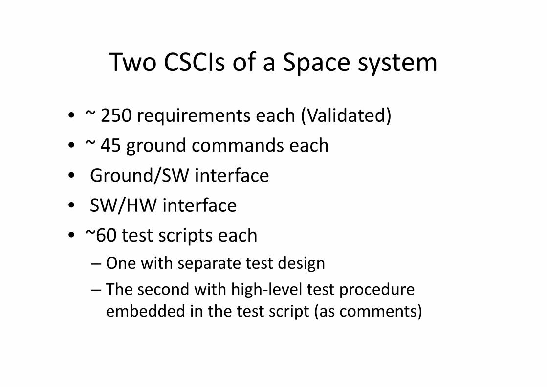
Two CSCIs of a Space system
• ~ 250 requirements each (Validated)
• ~ 45 ground commands each
• Ground/SW interface
• SW/HW interface • SW/HW interface
• ~60 test scripts each
– One with separate test design
– The second with high-level test procedure
embedded in the test script (as comments)
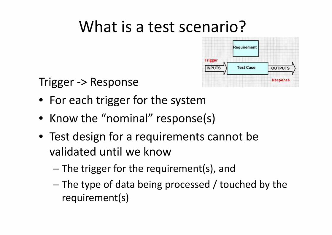
What is a test scenario?
Trigger -> Response
• For each trigger for the system
• Know the “nominal” response(s)• Know the “nominal” response(s)
• Test design for a requirements cannot be
validated until we know
– The trigger for the requirement(s), and
– The type of data being processed / touched by the
requirement(s)
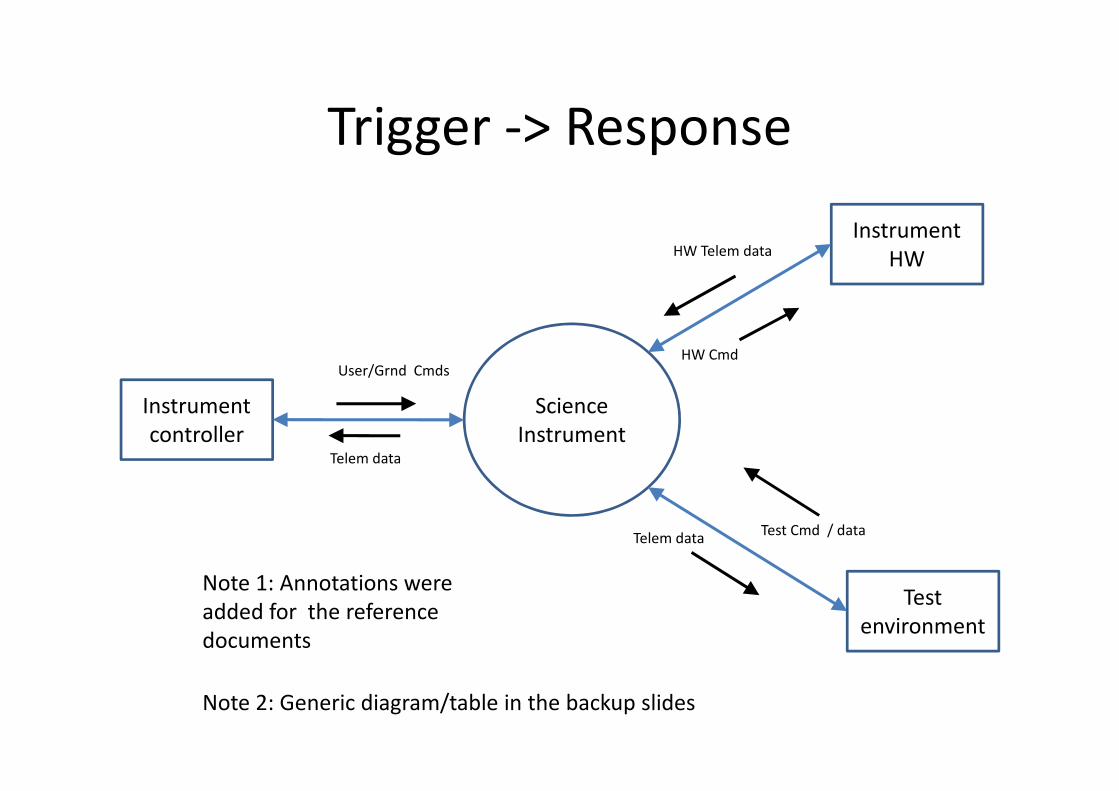
Trigger -> Response
Science Instrument
Instrument
HW
User/Grnd Cmds
HW Telem data
HW Cmd
Science
Instrument
Instrument
controller
Test
environment
Telem data
Test Cmd / dataTelem data
Note 2: Generic diagram/table in the backup slides
Note 1: Annotations were
added for the reference
documents

Space System Triggers / Responses
• Triggers
– External commands / HW telem aka across the interfaces
– Internal (a relatively small number) to the system
• Group the triggers (Single / multiple interfaces) • Group the triggers (Single / multiple interfaces) • User cmd impacting user interface only
• User cmd impacting User interface and hw interface
• Responses
– Internal to the system
– To the external interfaces

Test Design Validation Analysis &
Evidence– Test Scenario
• Test scenario trigger
• Test scenario step #
• Step description / behavior
– Reference info• Source (document section number, Req tag number)• Source (document section number, Req tag number)
• Safety (or other -illities related to the test step)
• Adverse conditions (if any)
– Evidence info• Correlation to the test plan section
• Correlation to the test procedure (number, step)
• Correlation to the test script (code line number)
– Observations / Issues (if any)
Test Design Issues Discovered
• Incomplete Arm / fire Commands tests
• Missing “Alternative” steps in the abort
scenario tests
– Off nominal for abort-sequence– Off nominal for abort-sequence
• Inadequate fault flag responses tests
• Incomplete Command parameter verification
tests
• Missing mode verification tests

Issue resolutions adequate?
• Really important
• Classic bug fix problem (Fix one but create
more)
– Developers updated the requirements, but the – Developers updated the requirements, but the
solution created additional issues with the
requirements and test design
• Test Design change impact analysis

Verifying the test results
• Test results Review
– Test logs
– Test terminal screen dumps
• Test results show • Test results show
– Commands executed
– Triggers identifiable
– Trigger occurred at the correct time
– System responses as expected
– Time stamps show if any deadlines violated

Lessons Learned
• Activity Diagrams are useful in complex scenarios
– Abort sequences
– Failure scenarios
• Test Scenario Format (depends on complexity, need to share with other team level, degree of usefulness)share with other team level, degree of usefulness)
– One paragraph
– Activity Diagram
– A page long set of steps
• Peer Reviews
– Peer reviews are the key in developing “realistic and correct” scenarios

Req-XXXX4 part (d) checks if
the “previous move status =
success”.
The “Move Status = success”
before the start of this AD it
will get reset to failure
because:
Req-XXXX9 inhibits the
commands in the activity #4
of this AD. Once the
commands are inhibited, the
“Move HW to Position-1” as
per Req-XXXX4 will fail, and
the “Move Status = Failed”
at decision point #1. Then
the program control will the program control will
reach Req-XXXX6 and again
fail because the “previous
move status = failure”.
The way this logic is set up,
the safing will always fail
unless, the HW movement is
permitted (HW move
command is un-inhibited).
Decision Point #1
Decision Point #2
Activity #4

Use of IV&V Test Scenarios for
analyzing Requirements and Design
For quick reference only. (Separate discussion)
• Requirement validation Phase
– Requirement testability at the early lifecycle
– Think how a given requirement would be part of the test scenario(s)test scenario(s)
• Design Verification Phase
– Design for testing
– Verify if the design is testable (based on the test scenarios developed during requirements validation phase)

Summary
• Using Q 1-3 approach helps develop comprehensive test scenarios
• Q 2-3 point to the Off nominal conditions
– Off nominal conditions are the source of high severity issues with Test designissues with Test design
• Identify and use system triggers as part of the test design val
• Look for safety-critical test scenarios
• Verify the test results
• Review the issue resolutions for additional/new bugs
Backup Slides

Validate Test Design Guideline
https://secureworkgroups.grc.nasa.gov/ivv-kmDocument Library � Validation � Processes �
Validate Test Design SLP Draft
• Guideline contains the “what” of the process.– References work instruction documents that contain the “how” of the
process.
– Depends on output from IVV PBRA and RBA processes for scope.– Depends on output from IVV PBRA and RBA processes for scope.
– Depends on output from Requirements Validation process.
• Recognizes that IV&V test design validation is iterative.– Uses generic set of lifecycle phases to indicate the likely order of tasks.
Does not prescribe a specific lifecycle.
• Provides an example list of artifacts, based on NPR 7150.2A and IEEE-829-2008, but recognizes that projects may tailor their artifacts.– Suggests mapping of recommended artifacts to the tailored artifacts
to ensure that the sources of expected content are identified.
Validate Test Design Work Instructions
https://secureworkgroups.grc.nasa.gov/ivv-kmDocument Library � Validation � Processes �
Validate Test Plan WI DraftValidate Test Design WI Draft
• Covers activities to be performed for in-scope behaviors and requirements.
• Indicates triggers for an iteration, expected inputs to the process, and expected outputs from the process.and expected outputs from the process.
• Generic lifecycle phases show which types of test plans are typically validated in which project phases.
• Addresses traceability to previous validation processes.
• Includes feasibility checks for test environment.
• Addresses validation of verification artifacts including test cases, demonstrations, analyses, and inspections, including appropriate use these verification methods.
References
Internal ReferencesNPR 7150.2A, NASA Software Engineering Standards, Sec 5.1.3
Public References IEEE 829-2008, IEEE Standard for Software and System Test Documentation
DO-178B, Software Considerations in Airborne Systems and Equipment Certification
IEEE 1012-2004, IEEE Standard for Software Verification and Validation
Private ReferencesUL Standards
NPR 7150.2A, NASA Software Engineering Standards, Sec 5.1.3
NPR 7150.2A, NASA Software Engineering Standards, Sec 3.4
NASA STD-8719.13B w/Change 1, Software Safety Standard
NASA-GB-8719.13 (2004), NASA Software Safety Guidebook
NASA-STD-8739.8, NASA Software Assurance Standard
NASA-GB-A201, NASA Software Assurance Guidebook
IVV 09-1 Revision: M, Independent Verification and Validation
References Are Important – Because:They help define the answers to
Question 1, what is the software supposed to do.
• Question 2, what is the software not Supposed to do?
• Standards mandated by law• Standards mandated by law
• NASA Policy Directives
• NASA Technical Standards
• NASA Contract Requirements
• Other Government Standards
• National or International Consensus Standards recognized by Industry
31
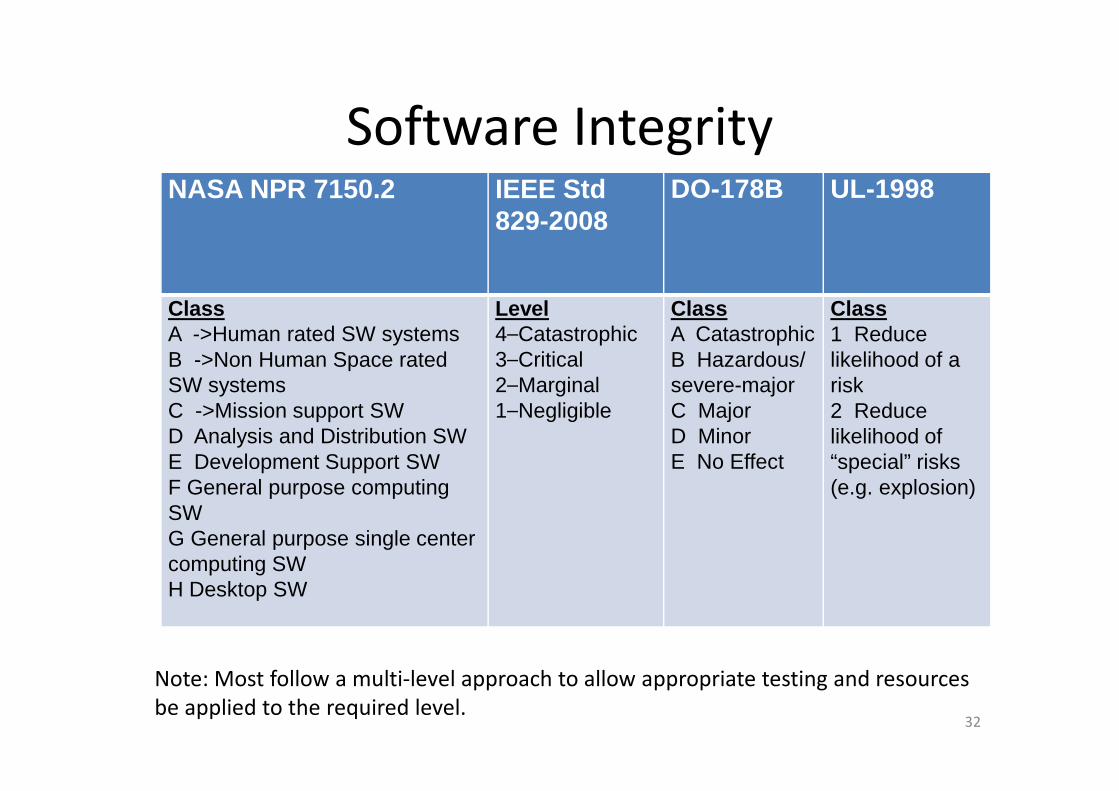
Software IntegrityNASA NPR 7150.2 IEEE Std
829-2008DO-178B UL-1998
ClassA ->Human rated SW systems B ->Non Human Space rated SW systems
Level4⎯Catastrophic3⎯Critical2⎯Marginal⎯
ClassA Catastrophic B Hazardous/ severe-major
Class1 Reduce likelihood of a riskSW systems
C ->Mission support SWD Analysis and Distribution SWE Development Support SWF General purpose computing SWG General purpose single center computing SWH Desktop SW
⎯
2⎯Marginal1⎯Negligible
severe-majorC MajorD MinorE No Effect
risk2 Reduce likelihood of “special” risks (e.g. explosion)
32
Note: Most follow a multi-level approach to allow appropriate testing and resources
be applied to the required level.
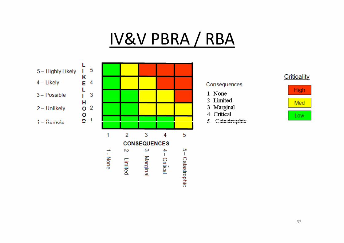
IV&V PBRA / RBA
33

The Master Test Plan
o Scope *o References *o Test Levels (Processes or Tasks) *o Tools , Techniques, Methods *o Inputs *o Outputs *o Master Test Schedule *o Resources summary *
• System Overview *• Test Overview *• Management
o Anomaly resolution *� Regression Testing *� Deviation policy *� Configuration
Management *o Resources summary *o Risks/Assumptions/Contingency *o Roles and Responsibilities *
Management *• Change
Procedures *
34
Test is to help ensure that:The System (software) does what it is supposed to do.
The System (software) does not do what it is not supposed to do.The system (software) responds appropriately to/under adverse conditions?
* Listed in IEEE-829

Lower Level Test Planso Scope
� Item to test� Features to test/not to test
o Level in Sequenceo Referenceso Approach
� Pass/Fail Criteria
o Taskso Risks/Contingencyo Inputs (Entrance criteria)o Deliverables (outputs)o Roles and Responsibilitieso Management
� Anomaly resolution� Coverage
o Resourceso Scheduleo Traceability Matrix
� Regression Testing� Deviation policy� Configuration
Management• Change Procedures
35
Test is to help ensure that:The System (software) does what it is supposed to do.
The System (software) does not do what it is not supposed to do.
The system (software) responds appropriately to/under adverse conditions?

Test Plans• Acceptance Test Plan
– Test coverage of system requirements; and
– Feasibility of operation and maintenance (e.g., capability to be operated and maintained in accordance with user needs).
• System Test Plan– Test coverage of system requirements;
– Appropriateness of test methods and standards used;
– Feasibility of system qualification testing; and
– Feasibility and testability of operation and maintenance requirements.– Feasibility and testability of operation and maintenance requirements.
• Software Final Qualification Test Plan
• Software Integration Test Plan
• Component Test Plan (Unit or Module Test)
• Regression
36
Note: Traceability is an important aspect of all plans.
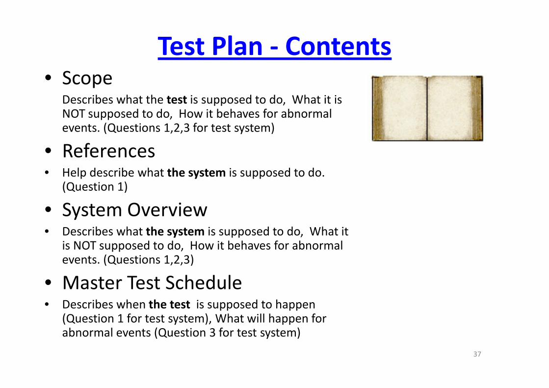
Test Plan - Contents• Scope
Describes what the test is supposed to do, What it is NOT supposed to do, How it behaves for abnormal events. (Questions 1,2,3 for test system)
• References• Help describe what the system is supposed to do.
(Question 1)
• System Overview• Describes what the system is supposed to do, What it
is NOT supposed to do, How it behaves for abnormal events. (Questions 1,2,3)
• Master Test Schedule• Describes when the test is supposed to happen
(Question 1 for test system), What will happen for abnormal events (Question 3 for test system)
37
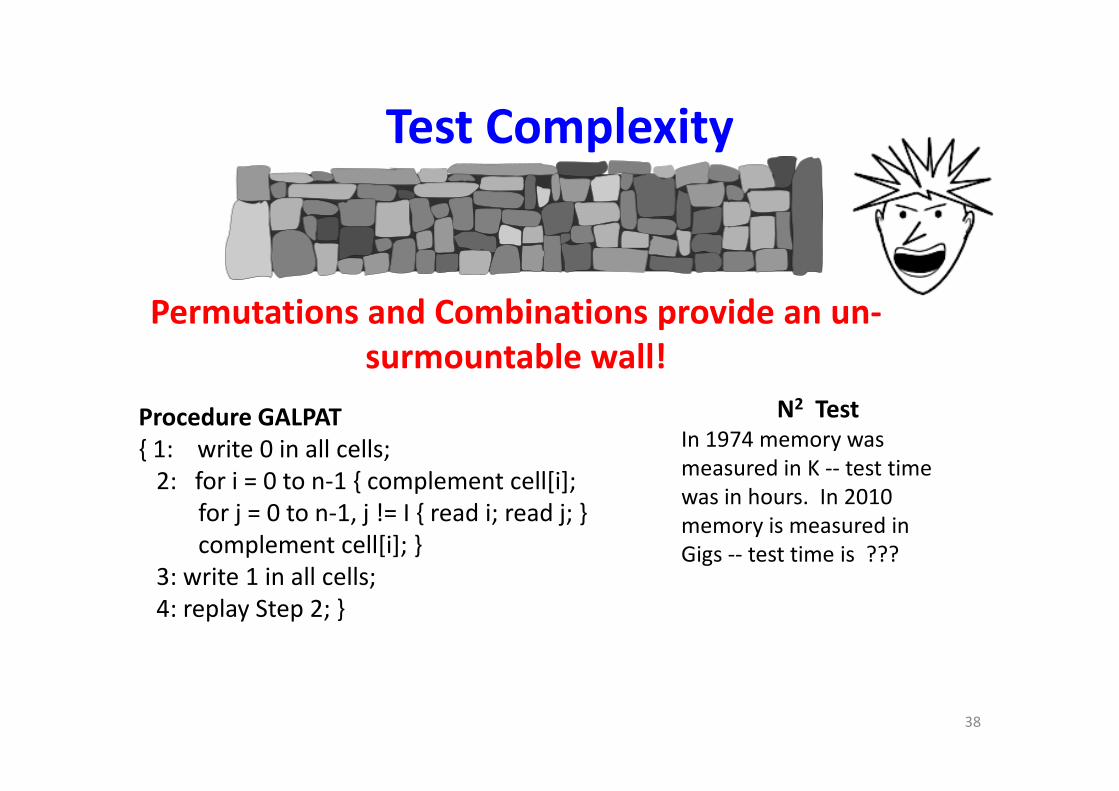
Test Complexity
N2 Test
Permutations and Combinations provide an un-
surmountable wall!
Procedure GALPAT
{ 1: write 0 in all cells;
2: for i = 0 to n-1 { complement cell[i];
for j = 0 to n-1, j != I { read i; read j; }
complement cell[i]; }
3: write 1 in all cells;
4: replay Step 2; }
38
N2 TestIn 1974 memory was
measured in K -- test time
was in hours. In 2010
memory is measured in
Gigs -- test time is ???
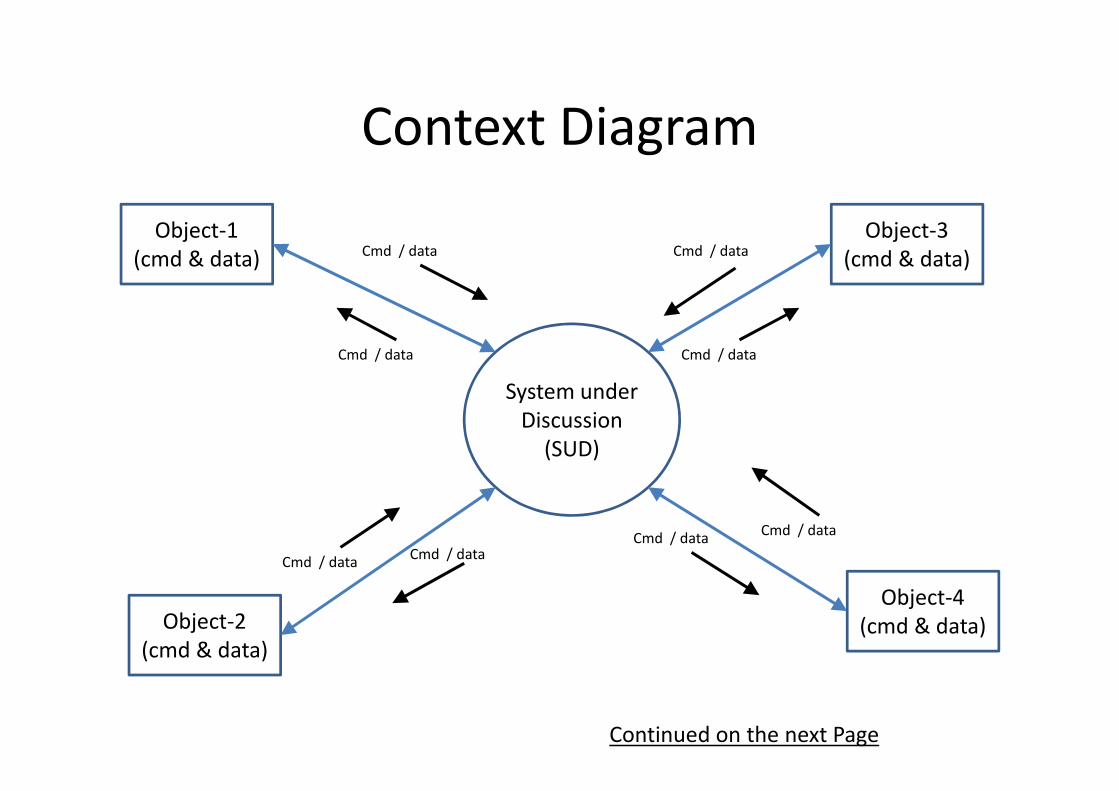
Context Diagram
System under
Object-1
(cmd & data)
Object-3
(cmd & data)Cmd / data
Cmd / data
Cmd / data
Cmd / data
System under
Discussion
(SUD)
Object-2
(cmd & data)
Object-4
(cmd & data)
Cmd / dataCmd / data
Cmd / dataCmd / data
Continued on the next Page

OR
Context Table(better for documenting the details)
Source /
Destination
Object
List Cmd &
data
Obj-> SUD
SUD behavior List Cmd &
data
SUD-> obj
SUD behavior
1 (obj name) 1a. Cmd A, B
1b. Data X,Y
1a. SUD will do ____ to
process the Cmd /data
1b.
1A. HW Cmd a
1B. HW telem x
1A. SUD will do _____ to
generate the Cmd/data
1B.
2 (obj name) 2a. Cmd C
2b. Data Z
2a.
2b.2A. Cmd/Data
2B.
2A. Behavior
2B.
3 (obj name) 3a. Cmd or data
3b. Cmd or data
3a.
3b.3A.
3B.
3A.
3B.
4 (obj name) 4a. Cmd or data
4b. Cmd or data
4a.
4b.4A.
4B.
4A.
4B.

From Nominal to Off-nominal test
scenarios
• Nominal scenario is the first step
– Q1 usually drives this step
• Emphasis on off-nominal scenarios
– Decomposing the system specs – Decomposing the system specs
– Applying Q2 and Q3 by searching for adverse
conditions that could break the system