ivc smart cameras - chronos · pdf fileivc smart cameras . issue date ... connect to the...
TRANSCRIPT

FAQ IVC Smart Cameras

Issue date 2011-08-10
Issued by Application Engineering
Approved by FF
Page 2 (38)
Title FAQ - IVC
Version 1.10
Document History
Version Comment Date
1.0 Created 2008-09-16
1.01 Added FAQs C08, C09 and T02
2009-01-16
1.02 Added FAQ C17 2009-02-12
1.03 Added FAQs U05 and U12 2009-03-23
1.04 Added FAQ S03 2009-08-31
1.05 Added FAQ U14 2009-12-02
1.06 Updated FAQ S03 2010-02-22
1.07 Added FAQ U15, updated U12
2010-06-29
1.08 Added FAQ T07 2010-09-01
1.09 Updated S03 2011-04-29
1.10 Updated FAQs U05, U07, U14, Q05, M01, M05, A01,
T02
2011-08-10

Issue date 2011-08-10
Issued by Application Engineering
Approved by FF
Page 3 (38)
Title FAQ - IVC
Version 1.10
Table Of Contents
DOCUMENT HISTORY ................................................................................... 2
TABLE OF CONTENTS .................................................................................. 3
SOFTWARE AND USAGE.............................................................................. 5
U01 – Why can't I connect to the IVC camera? .................................................................................. 5
U02 – Why does IVC Studio respond slowly?...................................................................................... 6
U03 – Why does IVC Studio crash when opening a visualization window?...................................... 7
U05 – Why do I get Error in Update in IVC Camera Updater? ........................................................ 8
U07 – Why don't I see an image in RUN mode? .................................................................................. 9
U08 – Why is my product file so large? .............................................................................................. 10
U12 – Why is the device file of my camera sometimes reset or the flash formatted? ..................... 10
U14 - Why will my program in bank 0 not run on boot up .............................................................. 11
U15 – How do I include error handling in my IVC step program? ................................................. 13
COMMUNICATION INTERFACES ............................................................... 16
C07 – Why are there strange live image results using the Web Interface?.....................................16
C08 – Where can I find information and example code for the IVC COM interface? .................. 17
C09 – Why do I get problems using the COM example programs?.................................................18
C12 – Is it possible to communicate with the IVC camera remotely?.............................................. 19
C17 – Why do the values from the OPC server have different timestamps? .................................. 20
RETRIEVING IMAGES ................................................................................. 22
Q05 – How do I setup overlapping images? ....................................................................................... 22
Q06 - Why are there zeros in the first row of the first grabbed image?.......................................... 23
EXTERNAL IMAGE PROCESSING.............................................................. 24
F02 – What is the structure of the .IMG file? How can I import it into for example Matlab? ..... 24
THE SENSOR ............................................................................................... 25

Issue date 2011-08-10
Issued by Application Engineering
Approved by FF
Page 4 (38)
Title FAQ - IVC
Version 1.10
S01 – What are the optical characteristics of the IVC-2D sensor? .................................................. 25
S03 - What are the guaranteed field of views for the different IVC-3D cameras? ......................... 26
MEMORY ISSUES ........................................................................................ 28
M01 – What is the number of maximum image/profile banks to use?............................................. 28
M05 – Why do I get ITF error 2 when executing Save Image/Databank to flash? ........................ 28
ENCODER ISSUES ...................................................................................... 30
A01 – How do I connect my encoder to the IVC-3D? ....................................................................... 30
PERFORMANCE .......................................................................................... 32
P01 – How do I increase the profile rate of my IVC-3D? ................................................................. 32
TOOLS .......................................................................................................... 33
T02 – Can I use the same Grab Setup step for different camera models?....................................... 33
T07 – How do I use the Coordinate Alignment Tools? ..................................................................... 34

Issue date 2011-08-10
Issued by Application Engineering
Approved by FF
Page 5 (38)
Title FAQ - IVC
Version 1.10
Software and Usage
U01 – Why can't I connect to the IVC camera? The device can not be found in the Ethernet Device Configuration list (Options → Configurations → Ethernet Devices → Ethernet Device Configuration)
1. Make sure that the power and network cables are connected. When connected and powered on the ON LED and the link LED on the IVC camera should turn green. Is the data LED flashing? It should flash when for instance updating the device list?
2. If the network cable is connected directly to your computer and not via a switch, you need to make sure that your network card handles automatic crossover, otherwise you need to use a crossover adapter.
3. If the device is connected through a switch (10/100 Mbps), make sure that the uplink port is not shared with another jack and that not both of those jacks are used.
4. You can not be connected via a hub, use a switch instead. 5. If there is a firewall on the network, it needs to be disabled. In the Windows firewall
you can as an alternative make an exception for IVC Studio. Consider possible built in firewalls in anti virus programs.
6. See also list entry 10 below.
The device can not be found in the Device list
7. If you have more than one network card make sure that you have chosen the correct Local IP that the camera is connected to.

Issue date 2011-08-10
Issued by Application Engineering
Approved by FF
Page 6 (38)
Title FAQ - IVC
Version 1.10
8. Check the Ethernet Device Configuration Settings in IVC-Studio:
DHCP server is used
a. Check if DHCP is turned on. If DHCP is on, is there a DHCP-server on the network?
b. If DHCP is turned on, but there is no DHCP server present, check the DHCP IP Auto Configuration setting. If this is set to 1 the device will get an IP address 0.0.0.0 and these are not shown in the device list. If the DHCP IP Auto Configuration setting is set to 0 the device will get its last known address. Make sure that there is no collision for this address. Also, make sure that the IP is on the same subnet.
DHCP server is not used
c. If DHCP is not to be used, disable DHCP and set a fix IP-address. (Double-click the IP-address) Make sure that the camera and the computer is on the same subnet.
d. Press the Update button followed by the Reset device button.
9. If the device does not show up immediately, wait 15-20 seconds, the camera needs time to reset. Press Ctrl+F5 to update the list.
The device is in run mode
10. If a program stored in bank 0 in the flash memory is malfunctioning, for example not being compatible with new firmware, that program will stop with an error, making it impossible to connect to the device. (It might be visible in the device list, but locked in run mode.) Restarting the device will not help, since program 0 is automatically started when the device is powered up.
a. Connect a high input signal (supply voltage) to pin 8 on the IVC RS485 connector, and restart the device. The device should now start without running the program in bank 0.
b. Connect to the device and delete the program in bank 0.
U02 – Why does IVC Studio respond slowly? If the camera is responding slowly make sure that the camera is connected to the PC in the right way.
See FAQ entry U01 – Why can't I connect to the IVC camera.
If connected in the right way, please read the following:
1. If there are more cameras connected to the same network and one of them has been removed from the network or lost the connection, IVC Studio will repeatedly try to connect to this camera and therefore overload the network. The solution is then to enter the device list and update (Ctrl + F5)
2. If setting a high timeout the IVC Studio can appear slow. Try to reduce the timeout setting. (Options -> Configuration -> Timeout) Default setting is 2500 ms.
3. If you received the error message: “The Device is performing a lengthy operation…” you have probably executed a step that takes longer to execute than the IVC Studio timeout. You might also have lost the connection to the camera and IVC Studio can not e.g. display the image bank.

Issue date 2011-08-10
Issued by Application Engineering
Approved by FF
Page 7 (38)
Title FAQ - IVC
Version 1.10
You get two options from the popup window:
• Retry – will keep you in program view, displaying the step program
• Cancel – will display the Device List
If the timeout is exceeded; Retry will give you a chance to either change the timeout or the tool parameters. If the connection is lost, Cancel will probably be the best choice and if the camera is not found in the device list a reboot of the camera might be necessary.
U03 – Why does IVC Studio crash when opening a visualization window? There is a known problem that sometimes occur when viewing the 3D visualization window in IVC Studio (visualization window crashes) if some ATI graphic cards are used. At the moment, these are not supported by IVC Studio. One workaround is to decrease the graphics hardware acceleration. To do so, follow the instructions below.
1. Start → Settings → Control Panel → Display → Tab: Settings → Advanced → Tab: Troubleshoot
2. Move the slider to a level able to display the visualization window in IVC Studio

Issue date 2011-08-10
Issued by Application Engineering
Approved by FF
Page 8 (38)
Title FAQ - IVC
Version 1.10
U05 – Why do I get Error in Update in IVC Camera U pdater? If you are unable to upload firmware to the camera it can have a number of explanations, e.g. damaged cables or hardware components, lack of a switch (a hub will not work), general software compatibility problems or signal disturbance. Firewalls can affect the update procedure as well so if there is one activated, turning it off is recommended. Also, make sure that the camera is in stop mode (not running) and that no programs are stored in the flash memory. These things should always be checked first, but if it still is impossible to update the camera it may have to do with a mismatch between the MTU setting of the network card and the IVC. MTU stands for “Maximum Transmission Unit” and defines the largest data packet possible to send/receive in bytes for a network device. The default MTU setting in Windows XP is 1500 bytes for Ethernet and this is the very same value as the IVC camera uses. If the MTU of the network card and the IVC do not match, the packets have to be split up into smaller parts (IP packets) in order to be sent/received. In general, splitting and reassembling data is common procedure in the TCP/IP standard but for some settings the camera cannot handle these operations in a stable manner and as a consequence the update fails. How to alter the MTU of a network card in Windows X P
The workaround for the update problems is simply to set up the MTU of your network card to 1500 bytes and this can be done in the following way:
1. Open the Registry Editor (Start -> Run -> <type in: regedit> -> <press: enter-key>) 2. Browse to the correct directory of your network adapter:
My Computer\ HKEY_LOCAL_MACHINE\ System\ CurrentControlSet\ Services\ Tcpip\ Parameters\ Interfaces\ <ID of Network adapter>
(If you do not know the ID of your network adapter you can look at the “key” called IPAddress which contains the IP address of the card.)
3. Create a new DWORD value with the correct MTU settings: [Right click] -> New -> DWORD Value -> [Name it “MTU”] -> [Double click to open] -> [Select “decimal” and enter the value “1500”]
4. Restart the computer 5. Done – try updating again

Issue date 2011-08-10
Issued by Application Engineering
Approved by FF
Page 9 (38)
Title FAQ - IVC
Version 1.10
NOTE! Changing registry keys can affect the performance of your computer and if done in the wrong way can require a complete reinstallation of your operating system. SICK does not take any responsibility for any problems caused by altered registry keys. If you do not want to change the registry key directly a network optimizing program can be used instead.
Checklist of things to test
1. Make sure you can connect to the camera through IVC Studio properly
a. If it does not work, see U01
2. If connected within a network, make sure only the camera and PC are running. Preferably, set up a small isolated network with a camera, switch and PC.
3. Disable any existing wireless network adaptors
4. Disable any existing VPN connections (e.g. “secure client”)
If it still does not work:
5. Try using a switch between the camera and PC if connected peer-to-peer
6. Try a different computer
U07 – Why don't I see an image in RUN mode? If no image is shown in run view (after having pressed F6), it is most likely due to one of the following reasons:
• The firewall doesn't allow communication on the port number that is used for sending images.
• The tool Enable Ethernet has been used previously with argument False, i.e. Ethernet communication has been disabled in the camera.
• There is an error in the step program
Firewall If the firewall blocks the communication, you have the following options:
Disable the firewall. (NB! Be aware of the risk if the computer is connected to the internet or a network)
Make an exception for IVC Studio in the firewall software.
Advanced users: In the firewall software, allow communication on the specific ports IVC Studio is using: 1001 and 1003 for UDP broadcasting, 1101, 1248, and 1250 for live image and additional ports set for the Ethernet tools.
It is often enough to make an exception for IVC Studio in the Windows XP firewall (Control Panel -> Security Center -> Firewall). Note that many antivirus programs have built-in firewalls in addition to the Windows XP firewall.

Issue date 2011-08-10
Issued by Application Engineering
Approved by FF
Page 10 (38)
Title FAQ - IVC
Version 1.10
Enable Ethernet Tool
Add the tool Enable Ethernet (found on the Communication tab) in the beginning of the program. Argument = True
Error in step program
Step through your program using F8 to make sure there is no error on the way. Add some kind of error handling to let the program know what to do if an error occurs.
Lost synchronization
If the camera and IVC Studio has lost their synchronization for some reason, it can be restored in the following ways:
• In IVC Studio: click the program in the tree-structure to the left
• Restart IVC Studio
• Restart IVC Studio and the camera
U08 – Why is my product file so large? In IVC releases prior to IVC Studio 2.7 the product files are not saved in an optimal way and can grow very large. These files can either be opened in 2.7, and saved as a new file, or be sent to tech-support for optimization.
In IVC Studio 2.7 and later releases the product file is optimized each time it is being saved, this makes the saving process of the product file take a little bit longer.
U12 – Why is the device file of my camera sometime s reset or the flash formatted? This problem was resolved in release 3.1 SR1 and should only affect older versions of IVC Studio. If you are using an IVC release prior to 3.1 SR1 and experience this problem, please upgrade to the latest version.
If you are using 3.1 SR1 or newer and still have this problem, please contact technical support.

Issue date 2011-08-10
Issued by Application Engineering
Approved by FF
Page 11 (38)
Title FAQ - IVC
Version 1.10
U14 - Why will my program in bank 0 not run on boo t up
Possible reasons
1. Flash dead size is maxed out - no free disk space 2. The program in bank 0 is created with another IVC Studio version than the one in the
camera 3. The file on flash is damaged 4. A Communication setup step is executed before Ethernet-IP is ready 5. Pin 8 on the IVC-3D RS485 connector is set high
Descriptions and solutions
1. Flash dead size is maxed out - no free disk space
Dead Size means fragmented data and these sectors cannot be used for storing. If this becomes too high there will no longer be any free space on the disk and the camera will not be able to boot from bank 0.
To view the dead size, open up the device settings and read off the flash parameters (FFS) as illustrated in the image below. The device information window is reached by: Right click on the device -> Flash -> Device information.

Issue date 2011-08-10
Issued by Application Engineering
Approved by FF
Page 12 (38)
Title FAQ - IVC
Version 1.10
Workaround 1
To restore the flash dead size to zero, you select “Clear unused memory”. This is done by the following procedure (image below): Right click the device -> Flash -> Clear unused memory.
Workaround 2
Since version 3.1 SR2 a setting called ‘DeadSpaceThreshold’ exists in SmartReader.ini, found on the camera flash. As the name hints at, this setting controls the maximum allowed dead space in flash. Each time the camera is booted up, this parameter is compared with the actual amount of dead space of the camera. If the unused and inaccessible memory exceeds the threshold setting, these sectors will be reformatted. As long as the DeadSpaceThreshold is not set too high and the camera is rebooted every now and then, the camera dead size should never have to be maxed out.
2. The program in bank 0 is created with another I VC Studio version than the one in the camera
If a program and table is transferred from one camera to another (PRG-file), one has to make sure that both cameras are running the same IVC version. If that is not the case, there is a risk that the program does not function properly on the new camera. Ideally, the project file should be used for this instead of downloading and uploading PRG-files.
Workaround 1
Downgrade the new camera to the same IVC version as the old camera. Please avoid this if possible as bugs are continuously fixed to make the product more stable.
Workaround 2
If no project file is present, do the following (go directly to point 4 if you have the project file):
1. Connect the “old” camera to IVC Studio 2. Create a new project 3. Import the program files from the camera and save the new product file

Issue date 2011-08-10
Issued by Application Engineering
Approved by FF
Page 13 (38)
Title FAQ - IVC
Version 1.10
4. Open up the project file just saved but in the IVC Studio version that runs on the new camera
5. Resave the project – this will convert the file to the new version 6. Open up the project file and save the programs and tables to flash
3. The file on flash is damaged
If the file on the camera cannot be imported in IVC Studio, there is a risk that it has become corrupt. It can also be that the file became damaged during the download process from the camera to IVC Studio.
Workaround
Make sure the Ethernet communication works as it should and try downloading the file again. If the connection is unstable you can never be sure the download process has come through – it may take a couple of tries and then it suddenly works.
4. A Communication setup step is executed before E thernet-IP is ready
When the camera is started it stakes about 10 seconds until it is up and running. If Ethernet-IP is used in the step program it will take an additional 20 seconds for it to function.
A program stored in bank 0 will be executed once the camera is ready - 10 seconds - and if the Communication setup step is reached before the additional 20 seconds has passed, the program will be stalled.
Workaround
Add a wait step of 20 seconds in the beginning of the program. This step should only be run once.
5. Pin 8 on the IVC-3D RS485 connector is set high
To override bank 0 boot-up, pin 8 on the RS485 connector can be set high. If this has been done recently the signal can be checked to be on the safe side.
U15 – How do I include error handling in my IVC st ep program? One of the keys to designing robust vision systems is to make sure it can handle all types of unexpected results. It is therefore important that all IVC step programs can handle all possible errors that might occur while the application is running. If there is no error handling included, the program will stop if an error occurs and it is impossible to understand the cause. In this FAQ we will look at two types of error handling that can be used in your application.
Error recovery
The first way to handle errors is through the error handler tool, ‘If Error Goto’. This step can, for example, be added at the beginning of a small program, or at the beginning of each part in

Issue date 2011-08-10
Issued by Application Engineering
Approved by FF
Page 14 (38)
Title FAQ - IVC
Version 1.10
a larger program. You can decide what should happen if an error occurs. If a program step returns an error, the program either skips this step and continues with the following step, or jumps to a defined program step. Recommended is to add an error handling routine in the program and jump to this section when an error occurs. In this error handling section, you can then check the results of the If Error Goto step, which will indicate which step caused the error and also the error code. These results along with conditionals (if steps) are good to have when determining how to handle an error.
The level of error handling is up to you to design. It could range from just signalling that an error has occurred and then going back to the main part of the program regardless of error to sophisticated logical constructions depending on the requirements of your vision system. It is also possible to have several different If Error Goto steps in a program. It is always the last executed step that is valid, but sometimes you want to keep track of several errors at a time. With information from more than one If Error Goto step, you can create more complex and advanced error handling routines. Often one If Errror Goto step is enough, though.
More information about the If Error Goto step and detailed information about its settings can be found in the reference manual.
Example of program structure when including error handler:
Error handling when using macros
When using macros it is possible to have If Error Goto steps inside the macros. However, when executing a macro with an If Error Goto step inside it will override the “global” error handling. An error occurring later on in the program results in the program jumping back into the macro. A way to handle this is to add a new If Error Goto step after each macro call to resume the main error handling again.
Error avoidance The second type of error handling is “error avoidance” where you check inputs rather than waiting for errors. By predicting what errors could occur and by checking the inputs before running a certain step, you make sure that the step will give you a valid result. If the input is not correct it might be possible to modify the parameters to be within a valid range before the step is executed.
For example if you want to define a dynamic ROI as a rectangle five pixels outside the

Issue date 2011-08-10
Issued by Application Engineering
Approved by FF
Page 15 (38)
Title FAQ - IVC
Version 1.10
bounding box of an object. In that case first verify that the left edge of the object is at six pixels from the left edge and that the right edge is at least six pixels from the right edge. And of course perform the same verification in the other direction. You can also assert that the input to ROI Rectangle is always ok by setting the X coordinate to =max(0, “left edge of object” - 5). Do the same with the Y coordinate width and height parameters and you will know for sure that ROI Rectangle will not produce an error.
Example on how to avoid error:

Issue date 2011-08-10
Issued by Application Engineering
Approved by FF
Page 16 (38)
Title FAQ - IVC
Version 1.10
Communication Interfaces
C07 – Why are there strange live image results usi ng the Web Interface? The jpeg compression sometimes fails, causing corrupted Web Status Page images. To avoid this, bitmap images can be used instead of jpeg. Below is information how to use bitmap images instead of jpeg images without having to make any changes in the step program.
Using bitmap images
• Open a web browser and go to ftp://xxx.yyy.ccc.zzz (camera IP). User name: anonymous Password: guest
• Copy the status.html-file and open it in notepad.
• Replace "cgi-bin/display_bank.jpg?bank=1" by "cgibin/display_bank?bank=1&format=1" in the status.html file.
• Save the file in the same name and replace the old one in camera.
Now the status.html file is updated and will send only bitmap images to the web browser.

Issue date 2011-08-10
Issued by Application Engineering
Approved by FF
Page 17 (38)
Title FAQ - IVC
Version 1.10
C08 – Where can I find information and example cod e for the IVC COM interface? On the SICKIVP support pages, under the Manuals tab, you will find both a manual for the COM interface as well as some programming examples.
In the user forum, which you reach from the support pages as well, there are some additional examples on how to use the COM interface. They are found under SICK IVP Vision User Forum > IVC > Operator Interfaces and SICK IVP Vision User Forum > Application Development Kit .
• SICK IVP Vision User Forum > IVC > Operator Interfaces
o Advanced Blobber – COM
o COM interface example

Issue date 2011-08-10
Issued by Application Engineering
Approved by FF
Page 18 (38)
Title FAQ - IVC
Version 1.10
SICK IVP Vision User Forum > Application Development Kit
o Box Content completeness
o Dough Volume
C09 – Why do I get problems using the COM example programs? Problems when using the COM examples are most often related to faulty references in Visual Basic.
To avoid this there are two things that can be done.
1. Make sure that the following dll-files are included in the VB6 project folder: o ijl15.dll – located in the installation folder of IVC Studio o itf_utility.dll – located in the installation folder of IVC Studio o IVCStudio.dll – comes with any of the COM example programs
2. Make sure that you have the correct references in Visual Basic 6.0 to ensure that the ActiveX component is running properly. This is done in the following way: Open the Reference Window, (Project -> References) click the checkbox and select the correct file for the following two references:
� Software development kit for IVC Studio – Browse the IVCStudio.dll file now available in the VB6 project folder.

Issue date 2011-08-10
Issued by Application Engineering
Approved by FF
Page 19 (38)
Title FAQ - IVC
Version 1.10
� IVC Studio ActiveX EXE – Browse the IVC Studio.exe file in the IVC Studio installation folder
If you are using IVC Studio 2.7 or a later version some specific problems could for example be:
• The image is not visible/updated in the COM application
• Error messages “Object Variable or With Block Variable Not Set” or "Method ‘Item’ of object ‘_Devices’ failed in…"
The following re-registrations can solve these issues.
• Re-registration of the IVC Studio.dll:
1. Open the command prompt
2. Go to the VB6 project folder
3. Type: regsvr32 IVCStudio.dll
• Re-registration of IVCStudio.exe:
1. Open the command prompt (START >> run... >> type "cmd")
2. Go to the IVC Studio installation folder
3. Type: "IVC Studio.exe" /regserver
C12 – Is it possible to communicate with the IVC c amera remotely? The simple answer is: No!
The more complicated answer is: Yes, using remote desktop software such as VNC you can communicate with the IVC camera.
You will need the following:
1. A stationary local computer which has to be on the same subnet as the camera
2. A remote computer with direct access to the local computer

Issue date 2011-08-10
Issued by Application Engineering
Approved by FF
Page 20 (38)
Title FAQ - IVC
Version 1.10
3. The local computer needs to run a VNC server
4. The remote computer needs to have a VNC client installed After logging on to the local computer you will see its screen and you will be able to use the local computer as if you were sitting in front of it. What you will be able to do from the remote computer:
1. See the screen of the local computer.
2. Start and use programs, including IVC Studio.
3. Create and make changes to the step programs.
4. Update camera firmware (using IVC Camera Updater).
5. etc.
C17 – Why do the values from the OPC server have d ifferent timestamps? When using OPC communication a set of variables is defined to be shared with the rest of the network. The Communication setup tool is used for specifying which parameter in the buffer that should be mapped to a certain value in the IVC device’s working memory. These values that the IVC camera holds in memory can be read/written asynchronous to the step program. The actual reading and writing of values occurs when a Communication Read/Write tool is executed. This data can be accessed by a user from an OPC client through SOPAS OPC Server installed on a PC. See the figure below for an overview.
The OPC-Server reads each value by itself, there is no batch reading. The timestamp of a variable shown in the OPC-Client is the time, the variable was last updated. If a value doesn't change, the timestamp will stay the same. This means that the timestamp on the values can differ from each other. The values can have been updated while the reading is done, so that the last values read are newer than the first values read.

Issue date 2011-08-10
Issued by Application Engineering
Approved by FF
Page 21 (38)
Title FAQ - IVC
Version 1.10
For example if a set of 10 variables have been defined the following scenario can occur. The data is written from the step program and the OPC server starts accessing the values one by one. After 8 values have been accessed the step program writes new value to the variable set and the last two variables accessed by the OPC server will then have a later timestamp than the first 8.
The minimum update rate of a variable group the SOPAS OPC-Server supports is 250 ms. It depends on the number of variables the SOPAS OPC-Server needs to update, if this update rate make sense. At the connection layer to the IVC camera, the update of a variable takes approximately 15 ms - 30 ms. Therefore, with an update rate of 250 ms it is recommended to have a variable group of ca. 10 items. In most cases update rates of 1-2 second are more useful.

Issue date 2011-08-10
Issued by Application Engineering
Approved by FF
Page 22 (38)
Title FAQ - IVC
Version 1.10
Retrieving Images
Q05 – How do I setup overlapping images? When capturing 3D images in free-running image triggering mode, it is possible to capture overlapping images, which means that a certain number of profiles will be included in both the current and the next image. Overlapping images is especially useful when your objects are placed more or less randomly on the conveyor. If you don’t use an overlap the image borders risk “cutting” your objects in half making the analysis a lot harder. The typical example application is “cookie inspection”. Imagine cookies coming down a conveyor like in the figure below. The figure illustrates a series of three images (labelled 1, 2, 3).
In order to make the analysis as simple as possible each cookie should be represented in its entirety in at least one image. The image overlap then needs to be equal or greater than the cookie diameter. Overlapping images are configured in the advanced tab in Grab Setup. There are three settings that need to be considered: Image triggering mode, Image overlap and Profile distance.
• Image triggering should be set to free running
• Image overlap [profiles] & Profile distance [mm] will together define the overlap in mm.
1 2 3
Movement direction Image overlap

Issue date 2011-08-10
Issued by Application Engineering
Approved by FF
Page 23 (38)
Title FAQ - IVC
Version 1.10
If the diameter of the cookie in the above example is 35 mm and our profile distance is 0.25 mm the image overlap should be at least: 35 / 0.25 = 140 profiles.
Grab Setup parameters that affect the image overlap
Please note that the overlap must be a multiple of 16 and less than 50% of the number of profiles in the image.
Q06 - Why are there zeros in the first row of the first grabbed image? The first profile (Y=0) of the image contains missing data if you use continuous laser, regardless of how the image looks like.
The behaviour is by design; the first profile of the image is discarded and set to missing data. The reason for this is that the sensor has been integrating light for an indefinite time since the last image was acquired.
This behaviour is not valid when using overlapping images or flashed laser. With flashed laser you always have the same exposure time regardless of the time between two consecutive images.

Issue date 2011-08-10
Issued by Application Engineering
Approved by FF
Page 24 (38)
Title FAQ - IVC
Version 1.10
External Image Processing
F02 – What is the structure of the .IMG file? How can I import it into for example Matlab? The IMG-file consists of a header, a 16-bit image and an 8-bit image. The header consists of 38 16-bit words with information about e.g. IVC Studio version. On positions 30 and 32 (starting from 1) the width and height of the image are recorded respectively. Thereafter follows the 16-bit image (Width x Height x 16 bits) and finally the 8-bit image (Width x Height x 8 bits). Here is a Matlab example that reads the data and outputs three variables: the header, the 16-bit image and the 8-bit image. function [raw16, raw8, hdr] = read_raw3d(infile)
% function [raw16, raw8, hdr] = read_raw3d(infile) % % Reads IVC-3D .IMG file q = fopen(infile); hdr = fread(q,38, 'uint16' ); imgsize = [hdr(30) hdr(32)]; raw16 = fread(q, imgsize(1)*imgsize(2), 'uint16' ); if imgsize(2) > 1 %Image raw16 = reshape(raw16, imgsize(1), imgsize(2)); raw16 = double(raw16(:,1:end))'; else %Profile fclose(q); raw8=hdr; return ; end raw8 = fread(q, imgsize(1)*imgsize(2), 'uint8' ); raw8 = reshape(raw8, imgsize(1), imgsize(2)); raw8 = double(raw8(:,1:end))'; fclose(q);

Issue date 2011-08-10
Issued by Application Engineering
Approved by FF
Page 25 (38)
Title FAQ - IVC
Version 1.10
The Sensor
S01 – What are the optical characteristics of the IVC-2D sensor?
Here is the spectral response curve for the IVC-2D sensor without filter:
The IVC-2D has a removable built in IR-filter that blocks the wavelength around IR (as well as UV). To remove the filter take away the lens, loosen the two screws and take out the filter. The specification of the filter can be seen below.

Issue date 2011-08-10
Issued by Application Engineering
Approved by FF
Page 26 (38)
Title FAQ - IVC
Version 1.10
S03 - What are the guaranteed field of views for t he different IVC-3D cameras? Before IVC-3D cameras leave the factory, a unique calibration table is obtained and stored on the camera flash. The reason for this is to compensate for geometrical differences in each camera individual. Things such as laser mounting, angle of optics and other manufacturing deviations, are all compensated for to give the cameras as similar possible field of view properties as possible. With individual calibration tables, the measured height of a particular object will be the same for all cameras of a certain model.
The fact that each camera has its own calibration table can pose problems when developing applications since the valid field of views will vary as well. If the user specifies a stand-off or height range that is on the limit of what is possible – e.g. the bottommost part of the sensor – this region may not be valid on another camera. This is something that should be taken into consideration when setting up a vision system, as cameras may have to be replaced later on.
Below follows an image and a corresponding clarification of the different FOV parameters, which are stated in the tables further down in this FAQ. The new specification guarantees absolute mm values, divided into two cases:
1. Guaranteed FOV size
• The total and unique FOV for each individual camera (red trapezoids) • Useful when camera alignment is possible at installation to compensate for individual
variations in working distance • Typically possible in small deployments and for system integrator use
2. Guaranteed FOV size and position common for all u nits
• The common FOV, shared by all produced units (green trapezoid) • Useful to support easy replacements and repetitive installations, when individual
variations are not acceptable • Typical in repetitive deployments and for OEM use

Issue date 2011-08-10
Issued by Application Engineering
Approved by FF
Page 27 (38)
Title FAQ - IVC
Version 1.10
Notes:
• No changes have been made in production. What is new is that each device is verified to meet the exact specification in the final production test.
• The FOV specifications of the Stainless Steel models need to subtract 6.4 mm from the stand-off value because of the larger housing.
• The new specification is valid from serial numbers ‘1103 XXXX’ onwards.
Guaranteed FOV Size
*) The range indicates the allowed individual variation.
Guaranteed FOV Size and Position for All Units *) Depending on the camera model, a safety margin of 1-2 mm is added/subtracted to both extreme values (top/bottom and left/right, respectively) to compensate for inaccuracies in absolute values relative to the camera housing. On the total height and width, this sums up to 2-4 mm.
IVC-3D Stainless Steel
A special note needs to be added for the stainless steel cameras. The stand-off, as seen in the IVC Studio software, is the distance from the top of the FOV to the housing plus 6.4 mm. The reasons are that the stainless housing dimensions are larger and that these cameras are calibrated by the same method as the aluminum versions.
Variant IVC-3D 200 IVC-3D 50 IVC-3D 30 IVC-3D 300 IVC-3D 100
Stand-off (mm)* 288-306 182-195 203-208 265-282 252-265
Guaranteed height range (mm) 377 84 31 871 139
Guaranteed width near (mm) 436 134 53 417 179
Guaranteed width far (mm) 810 174 59 1297 255
Variant IVC-3D 200 IVC-3D 50 IVC-3D 30 IVC-3D 300 IVC-3D 100
Guaranteed stand-off (mm)* 308 196 209 284 266
Guaranteed height range (mm)* 356 70 26 850 125
Guaranteed width near (mm)* 432 132 51 413 177
Guaranteed width far (mm)* 806 172 57 1293 253

Issue date 2011-08-10
Issued by Application Engineering
Approved by FF
Page 28 (38)
Title FAQ - IVC
Version 1.10
Memory issues
M01 – What is the number of maximum image/profile banks to use? Since version 3.2 the amount of image banks possible is limited to allocate a maximum of 64 MB of RAM (of 128 MB total). If the user has configured too many image banks, the allocation of image banks will stop when the memory limit of 64 MB is reached.
This limitation was introduced in order not to allow over-allocation of the RAM memory, which could previously result in strange errors and timeouts. Please note that no releases prior to IVC Studio 3.2 have this safety limitation.
M05 – Why do I get ITF error 2 when executing Save Image/Databank to flash? When the flash memory has been used a lot it can become fragmented and this will cause the saving to flash tools execution time to increase. Depending on the size of the data block and/or image the saving time will vary. If the execution time is longer than the timeout setting the ITF Error = 2 will indicate this. See three solutions below:
Defragment camera flash memory
In the Device List right-click on your device -> Device Management -> Flash -> Clear unused memory

Issue date 2011-08-10
Issued by Application Engineering
Approved by FF
Page 29 (38)
Title FAQ - IVC
Version 1.10
Increase timeout
Options -> Configuration -> Hardware -> Timeout
Decrease data block size
If you are using the Teach shape tool try decreasing the data block size by reducing the number of found points in gradient mode or choose Gray level mode.

Issue date 2011-08-10
Issued by Application Engineering
Approved by FF
Page 30 (38)
Title FAQ - IVC
Version 1.10
Encoder issues
A01 – How do I connect my encoder to the IVC-3D? This text is refers to details in the knowledgebase article ‘Connecting Stegmann encoder to IVC-3D’ found on our support pages under the section FAQ/Knowledge base.
Requirements of the encoder
There are two requirements of the encoder connected to an IVC-3D:
1. The encoder must be an incremental encoder.
2. The encoder must have a TTL/RS422 interface. Typically, we recommend using SICK | STEGMANN encoders in the DRS61 C (or DRS61 A) series, as these fulfil the requirements. Further information about these encoders can be found on www.sick.com.
In the knowledgebase article there is a description on how to connect a SICK | STEGMANN encoder to an IVC-3D. When using other encoders, the pin connections on the encoder may differ, but on the IVC-3D they will always be the same.
Connecting an encoder to the IVC-3D How to connect an encoder to an IVC is explained thoroughly in the Knowledge Base article previously mentioned. In the article it is stated that either two or four of the signal cables can be connected. Depending on which of these options you select, the behaviour will be different. Due to changes in the encoder interface introduced in IVC Studio 3.1, the recommendation is to always connect all four wires. By doing so all existing modes can be utilized.
Encoder modes In IVC Studio 3.1 a new encoder interface with four new modes was introduced. These encoder modes require all four signal cables connected in order to function (A, A-, B, B-), and connecting all four is thus recommended.
The encoder mode setting is found in the configuration file ‘SmartReader.ini’ located on camera flash disk, and below follows an instruction on how to alter it.
1. Log on to the camera FTP-server (Username=anonymous, Password=guest).
2. Copy the old SmartReader.ini to the PC for backup.
3. Remove SmartReader.ini from the flash of the camera and restart the device (but be careful not to delete the calibration files). A new SmartReader.ini file with default values for all parameters will be created on the camera, also containing the new parameter called ‘EncoderMode’. Note! For cameras delivered with version 3.1 or higher, this step is not required.
4. Modify the relevant parameters of the new SmartReader.ini file to get the wanted behaviour, including “EncoderMode”.

Issue date 2011-08-10
Issued by Application Engineering
Approved by FF
Page 31 (38)
Title FAQ - IVC
Version 1.10
An explanation of the different encoder modes is found below.
• Mode 0: Encoder ticks increase regardless of direction.
• Mode 1: Encoder ticks increase/decrease depending on direction.
• Mode 2: Robust mode – recommended. Encoder ticks increase/decrease depending on direction and both channels must change to increment/decrement the counter.
• Mode 3: High resolution mode. A change in either encoder channel will increase the counter. I.e. the number of ticks/mm is 4 times the value of mode 0-2.
Note! Encoder modes 0, 1 and 3 are in some situations sensitive to vibrations and other types of noise. These problems are greatly reduced or eliminated by if using the Robust mode, mode 2.

Issue date 2011-08-10
Issued by Application Engineering
Approved by FF
Page 32 (38)
Title FAQ - IVC
Version 1.10
Performance
P01 – How do I increase the profile rate of my IVC -3D? Several parameters in the Grab Setup tool affect the highest possible profile rate, but the two most important are:
1. Height of the measurement FOV
2. Measurement mode
Grab Setup parameters that affect the (max) profile rate

Issue date 2011-08-10
Issued by Application Engineering
Approved by FF
Page 33 (38)
Title FAQ - IVC
Version 1.10
A measurement FOV optimized for high speed.
Tools
T02 – Can I use the same Grab Setup step for diffe rent camera models? You cannot always reuse a Grab Setup step created with another camera type, since the limits of possible field of view settings for different camera types differ. If a Grab Setup step with settings for one camera type is opened for another camera type, this would result in a lot of errors in the settings or, in the worst case, a crash of IVC Studio. To avoid this, the user is instead prompted to replace the Grab Setup step with a new one with settings that are valid for the current camera type.
When opening a product file with a Grab Setup step that has been created for a different camera type than the current one, you will get the following message:
There is one special case that can still cause a crash of IVC studio. If the Grab Setup step has settings for a IVC3D-300 camera, and these settings are just on the limit for this camera, you might get the above message from the Studio telling you that the Grab Setup step was created for another camera type. If you then switch to an IVC3D-200 camera and try to open the interactive setup for Grab Setup, IVC Studio will crash. In this case you need to replace the Grab Setup step and adjust the settings according to the requirements of your application.
Please note that the Emulator supports the FOVs of all produced units. If you encounter a FOV which does not work in the emulator, please contact technical support.

Issue date 2011-08-10
Issued by Application Engineering
Approved by FF
Page 34 (38)
Title FAQ - IVC
Version 1.10
T07 – How do I use the Coordinate Alignment Tools?
Introduction to Coordinate Alignment In robotics the IVC camera is often used to locate the position of an object. This position is sent to the robot, so the robot knows at what position to pick the object. The IVC camera and the robot have one coordinate system each, in which all calculations are made. From the IVC’s point of view, the camera coordinate system is called internal, whist the on in the robot is called external. To translate the position from the IVC camera coordinate system to the robot coordinate system, a transformation matrix needs to be calculated. This is done by using the Coordinate Alignment tool and the resulting transformation matrix is stored in a data block. The data block is later used in the Get calibrated point tool to transform the IVC coordinates to the corresponding external coordinate system.
NB! There are some helpful notes in the end of this document, so make sure you read the entire document before starting to calibrate .
2D Coordinate alignment The IVC-2D calibration target is available in the IVC installation Help folder as a PDF file. It looks like a chessboard and contains four crosses with corresponding letters as well as three dots in the chessboard. To print the calibration target in a correct way, it is important to follow the instructions found the calibration target.
There are two different options when calibrating an IVC-2D camera, either calibrate the camera to send internally calibrated mm data from the camera, or calibrate the camera to an external coordinate system, for example the coordinate system of a robot. For an internal calibration, follow the steps below:
1. Make sure that the calibration target is printed the way specified by the documentation.
2. Place the calibration target on a plane surface in the FOV of the IVC-2D and grab an image. Make sure that the contrast is good and that the whole target is within the field of view of the camera.
3. Add a Coordinate Alignment step in the step program and open the interactive setup

Issue date 2011-08-10
Issued by Application Engineering
Approved by FF
Page 35 (38)
Title FAQ - IVC
Version 1.10
4. Move the cross hair so that it is within one of the black squares of the chessboard.
5. Click Calculate and wait until the tool has found the three dark dots in the calibration target.
6. Save the data block.
External calibration in 2D To calibrate the chessboard to an external system, for example the coordinate system of a robot, the method is similar to what was described above, with some additions.
You will need to make sure that the crosses A, B, C and D of the calibration target are within the field of view. Also, make sure you can see the letters in the grabbed image. This will make the calibration easier, because you will know that you are calibrating the right cross.
When the crosshair is placed within one of the black squares, the tool will calculate the position of the crosses in the IVC coordinate system.
Next you will need to add the corresponding coordinates in the external coordinate system. If you are using a robot, you do this by pointing at the four crosses with the tip of a known tool in the coordinate system (frame) that you wish to use. NB! Note the coordinates of each position and save them in a comma separated file, according to the following syntax:
xA; y A; z A; <return> xB; y B; z B; <return> xC; y C; z C; <return> xD; y D; z D;
Also note that the file must be ANSI coded. Where xA is the x coordinate of reference point A and yB is the y coordinate of reference point B, etc. Make sure that A corresponds to A in the external coordinate system and so on. To increase the accuracy it is also possible to add more than one measurement per point:
xA1; y A1; z A1; x A2; y A2; z A2; ... ; x An; y An; z An <return> xB1; y B1; z B1; x B2; y B2; z B2; ... ; x Bn; y Bn; z Bn <return> xC1; y C1; z C1; x C2; y C2; z C2; ... ; x Cn; y Cn; z Cn <return> xD1; y D1; z D1; x D2; y D2; z D2; ... ; x Dn; y Dn; z Dn
Where xAn is the x coordinate for the nth measurement of reference point A. Do not forget to save your data block.
3D Coordinate alignment
The 3D coordinate alignment tool is making similar calculations as the 2D tool, but the interface and the calibration process is a bit different. In order to use the 3D tool, you will need a calibration object. There are three options when choosing calibration objects.
• The SICK IVP object is possible to order from SICK IVP. There are calibration objects for the IVC-3D 30, 50, 200 and 300 models.
• It is also possible to use a custom calibration object. This may be an option if not the entire field of view of the camera is used in the real application. When using a custom object, make sure you use at least six calibration points and that you place them on at least two different height levels.

Issue date 2011-08-10
Issued by Application Engineering
Approved by FF
Page 36 (38)
Title FAQ - IVC
Version 1.10
Please note that when using the SICK object, you will get sub-pixel resolution due to the fitting of the cones, compared to pixel resolution with a customized object, which is a manual process.
• To get sub-pixel resolution with a custom made object, build a calibration object that has six cones, with at least two different height levels and where each cone has an angle as shown below. Then you can follow the instructions of the SICK calibration object. Due to the laser triangulation technique, the surface of the cones must not be too reflective.
3D Coordinate alignment – SICK IVP calibration obj ect
1. Grab an image of the SICK calibration object. Please note that for the SICK calibration object, you need to use the whole field of view of the camera.
2. Add a Coordinate Alignment step in your step program and open the interactive setup
3. Change the Calibration object parameter to SICK | IVP target.
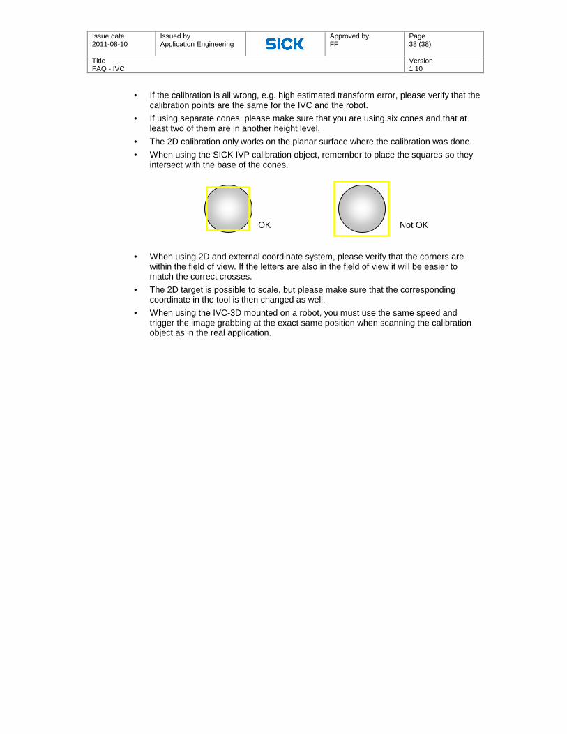
4. Six squares will appear at the top of the image. Place them over each cone and adjust the sizes of the squares so that they intersect the base of the cones, see image below.
5. Click Calculate all to calculate the coordinates of the tips of the cones.
6. Now you need to add the corresponding coordinates in the external coordinate system. If you are using a robot, you need to do this by pointing at the tip of the cone with the centre point of a known robot tool, using the coordinate system (frame) that you wish to use.
7. Click the Robot tab and enter the corresponding robot coordinates, this can also be done with a text file as described earlier.
8. Go back to the General tab and click Save. Enter a name for your transformation and click Ok.
9. After saving the data block, the transformation is calculated and the calibration between the two coordinate systems is made. Now you can also see the estimated transform error. Exit the Coordinate Alignment interactive setup window and disable the Coordinate Alignment step by right clicking the step and selecting Disable.
10. In order to also keep the calibration after powering off, you need to save the data block in the flash memory of the camera.
11. Add a Save Data Block to Flash step in your program and download your data block. Enter your data block number and execute the Save Data Block to Flash step.
12. Right click the Save to Data Block to Flash step and select Disable, to disable the step. Do not enable unless a new calibration is made.
84˚

Issue date 2011-08-10
Issued by Application Engineering
Approved by FF
Page 37 (38)
Title FAQ - IVC
Version 1.10
13. To always recover the data block after powering on the IVC camera, add a Load Data Block from Flash step in the beginning of your program.
3D Coordinate alignment – Custom target
1. Make sure that the calibration target has at least six calibration points in at least two different height levels.
2. Change the Calibration object parameter to Custom target and select the Number of points and measurements/points.
3. Position the crosshair at each calibration position and click Calculate. Since there is no fitting of the cones, as with the SICK | IVP calibration object, it is not possible to get sub-pixel resolution.
4. Enter the corresponding robot coordinates under the Robot points tab.
5. Select the General tab and click Save. Enter a name to your transformation and click Ok.
6. After saving the data block, the transformation is calculated and the calibration between the two coordinate systems is made. Exit the Coordinate Alignment interactive setup window and disable the Coordinate Alignment step by right clicking the step and selecting Disable.
7. Your transformation is now saved in the RAM memory.
8. To save the data block in the flash memory, follow the steps described earlier.
Notes
• Remember to download the data block into the flash memory; otherwise the data block will be lost after powering off and the calibration needs to be done all over again.
Issue date 2011-08-10
Issued by Application Engineering
Approved by FF
Page 38 (38)
Title FAQ - IVC
Version 1.10
• If the calibration is all wrong, e.g. high estimated transform error, please verify that the calibration points are the same for the IVC and the robot.
• If using separate cones, please make sure that you are using six cones and that at least two of them are in another height level.
• The 2D calibration only works on the planar surface where the calibration was done.
• When using the SICK IVP calibration object, remember to place the squares so they intersect with the base of the cones.
• When using 2D and external coordinate system, please verify that the corners are
within the field of view. If the letters are also in the field of view it will be easier to match the correct crosses.
• The 2D target is possible to scale, but please make sure that the corresponding coordinate in the tool is then changed as well.
• When using the IVC-3D mounted on a robot, you must use the same speed and trigger the image grabbing at the exact same position when scanning the calibration object as in the real application.
OK Not OK