itu-t rec. l.73 (04/2008) methods for inspecting and
TRANSCRIPT

I n t e r n a t i o n a l T e l e c o m m u n i c a t i o n U n i o n
ITU-T L.73TELECOMMUNICATION STANDARDIZATION SECTOR OF ITU
(04/2008)
SERIES L: CONSTRUCTION, INSTALLATION AND PROTECTION OF CABLES AND OTHER ELEMENTS OF OUTSIDE PLANT
Methods for inspecting and repairing underground plastic ducts
Recommendation ITU-T L.73

Rec. ITU-T L.73 (04/2008) i
Recommendation ITU-T L.73
Methods for inspecting and repairing underground plastic ducts
Summary After a conduit is installed in a trench and has been backfilled, but before any surface construction begins, it is common practice to check duct quality because certain plastic conduits can become oval-shaped, pierced or broken. Recommendation ITU-T L.73 describes inspection methods such as the use of test mandrels and closed-circuit television (CCTV) systems to check duct quality, and also describes various methods that are utilized to repair underground conduits. Repairing methods without digging, called "trenchless techniques" are introduced, and traditional repairing methods (dig and replace) is also presented. Additionally, guidelines for selecting appropriate repairing methods are proposed. It is expected that this Recommendation will provide alternative solutions for inspection and repair work.
Source Recommendation ITU-T L.73 was approved on 6 April 2008 by ITU-T Study Group 6 (2005-2008) under Recommendation ITU-T A.8 procedure.
Keywords CCTV, inspection, mandrel, repair, trenchless techniques, underground duct.

ii Rec. ITU-T L.73 (04/2008)
FOREWORD
The International Telecommunication Union (ITU) is the United Nations specialized agency in the field of telecommunications, information and communication technologies (ICTs). The ITU Telecommunication Standardization Sector (ITU-T) is a permanent organ of ITU. ITU-T is responsible for studying technical, operating and tariff questions and issuing Recommendations on them with a view to standardizing telecommunications on a worldwide basis.
The World Telecommunication Standardization Assembly (WTSA), which meets every four years, establishes the topics for study by the ITU-T study groups which, in turn, produce Recommendations on these topics.
The approval of ITU-T Recommendations is covered by the procedure laid down in WTSA Resolution 1.
In some areas of information technology which fall within ITU-T's purview, the necessary standards are prepared on a collaborative basis with ISO and IEC.
NOTE
In this Recommendation, the expression "Administration" is used for conciseness to indicate both a telecommunication administration and a recognized operating agency.
Compliance with this Recommendation is voluntary. However, the Recommendation may contain certain mandatory provisions (to ensure e.g. interoperability or applicability) and compliance with the Recommendation is achieved when all of these mandatory provisions are met. The words "shall" or some other obligatory language such as "must" and the negative equivalents are used to express requirements. The use of such words does not suggest that compliance with the Recommendation is required of any party.
INTELLECTUAL PROPERTY RIGHTS
ITU draws attention to the possibility that the practice or implementation of this Recommendation may involve the use of a claimed Intellectual Property Right. ITU takes no position concerning the evidence, validity or applicability of claimed Intellectual Property Rights, whether asserted by ITU members or others outside of the Recommendation development process.
As of the date of approval of this Recommendation, ITU had not received notice of intellectual property, protected by patents, which may be required to implement this Recommendation. However, implementers are cautioned that this may not represent the latest information and are therefore strongly urged to consult the TSB patent database at http://www.itu.int/ITU-T/ipr/.
© ITU 2009
All rights reserved. No part of this publication may be reproduced, by any means whatsoever, without the prior written permission of ITU.

Rec. ITU-T L.73 (04/2008) iii
CONTENTS
Page 1 Scope ............................................................................................................................ 1
2 References..................................................................................................................... 1
3 Definitions .................................................................................................................... 2
4 Abbreviations and acronyms ........................................................................................ 2
5 Conventions .................................................................................................................. 2
6 Methods for inspecting and repairing underground plastic ducts................................. 2 6.1 Inspection methods for underground ducts .................................................... 2 6.2 Repairing methods for underground ducts ..................................................... 4
Appendix I – Korean experience ............................................................................................. 9 I.1 Inspection methods......................................................................................... 9 I.2 Repairing methods.......................................................................................... 12
Bibliography............................................................................................................................. 13

iv Rec. ITU-T L.73 (04/2008)
Introduction Placing cables in conduits is preferred because it has a principle advantage that the cable placement operation is separated in time from the actual conduit construction phase. The protection of the cable with the passage of time and the possibility of repeated access, cable removal and delayed cable installation make the method of placing cables in ducts more attractive. The method, however, has a disadvantage in that the initial cost of conduit construction is expensive. It is noted that underground ducts are prone to being deformed by the burden of earth pressure, which makes it necessary to check the ducts before cable installation, and to repair defective ducts before placing cables in conduits.

Rec. ITU-T L.73 (04/2008) 1
Recommendation ITU-T L.73
Methods for inspecting and repairing underground plastic ducts
1 Scope This Recommendation: − makes a classification of different methods for inspecting and repairing underground ducts; − describes both trenchless methods and conventional methods; − is limited to the methods for underground ducts in which no cables are installed; − focuses on methods for underground ducts that have single-way duct unit systems and are
made of plastic materials such as polyvinyl chloride (PVC) and polyethylene (PE); − deals with pipes having diameters ranging from 90 to 110 mm.
2 References The following ITU-T Recommendations and other references contain provisions which, through reference in this text, constitute provisions of this Recommendation. At the time of publication, the editions indicated were valid. All Recommendations and other references are subject to revision; users of this Recommendation are therefore encouraged to investigate the possibility of applying the most recent edition of the Recommendations and other references listed below. A list of the currently valid ITU-T Recommendations is regularly published. The reference to a document within this Recommendation does not give it, as a stand-alone document, the status of a Recommendation.
[ITU-T L.1] Recommendation ITU-T L.1 (1988), Construction, installation and protection of telecommunication cables in public networks.
[ITU-T L.11] Recommendation ITU-T L.11 (1988), Joint use of tunnels by pipelines and telecommunication cables, and the standardization of underground duct plans.
[ITU-T L.35] Recommendation ITU-T L.35 (1998), Installation of optical fibre cables in the access network.
[ITU-T L.38] Recommendation ITU-T L.38 (1999), Use of trenchless techniques for the construction of underground infrastructures for telecommunication cable installation.
[ITU-T L.39] Recommendation ITU-T L.39 (2000), Investigation of the soil before using trenchless techniques.
[ITU-T L.40] Recommendation ITU-T L.40 (2000), Optical fibre outside plant maintenance support, monitoring and testing system.
[ITU-T L.46] Recommendation ITU-T L.46 (2000), Protection of telecommunication cables and plant from biological attack.
[ITU-T L.48] Recommendation ITU-T L.48 (2003), Mini-trench installation technique.
[ITU-T L.63] Recommendation ITU-T L.63 (2004), Safety procedures for outdoor installations.

2 Rec. ITU-T L.73 (04/2008)
3 Definitions This Recommendation defines the following term:
3.1 trenchless technology: Technology of installing, repairing or renewing underground ducts using methods that minimize or eliminate the need for excavation. The use of such techniques can reduce environmental impact, social costs and at the same time provide economic alternatives to traditional open-cut methods of installation, renewal or repair.
4 Abbreviations and acronyms This Recommendation uses the following abbreviations and acronyms:
CCTV Closed Circuit Television
LVDT Linear Variable Differential Transformer
PE Polyethylene
PVC Polyvinyl Chloride
5 Conventions None.
6 Methods for inspecting and repairing underground plastic ducts
6.1 Inspection methods for underground ducts
6.1.1 Classification of defects Some defects that may occur in plastic ducts are given in Table 1.
Table 1 – Classification of defects
Defects Causes
Crack or fracture Excessive pressure. Insufficient duct strength.
Duct failure Ground settlement. Excessive loads.
Pointed deformation Sharp shaped crushed stone. Oval shaped deformation Excessive pressure.
Insufficient duct strength. Dynamic compacting loads during construction.
Soil intrusion Disconnection of ducts. Offset Faulty construction.
Ground settlement.
Rec. ITU-T L.73 (04/2008) 3
6.1.2 Inspection methods
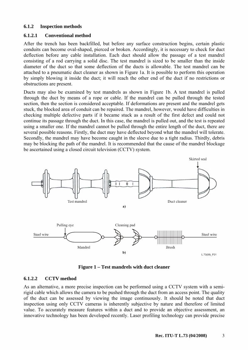
6.1.2.1 Conventional method After the trench has been backfilled, but before any surface construction begins, certain plastic conduits can become oval-shaped, pierced or broken. Accordingly, it is necessary to check for duct deflection before any cable installation. Each duct should allow the passage of a test mandrel consisting of a rod carrying a solid disc. The test mandrel is sized to be smaller than the inside diameter of the duct so that some deflection of the ducts is allowable. The test mandrel can be attached to a pneumatic duct cleaner as shown in Figure 1a. It is possible to perform this operation by simply blowing it inside the duct; it will reach the other end of the duct if no restrictions or obstructions are present.
Ducts may also be examined by test mandrels as shown in Figure 1b. A test mandrel is pulled through the duct by means of a rope or cable. If the mandrel can be pulled through the tested section, then the section is considered acceptable. If deformations are present and the mandrel gets stuck, the blocked area of conduit can be repaired. The mandrel, however, would have difficulties in checking multiple defective parts if it became stuck as a result of the first defect and could not continue its passage through the duct. In this case, the mandrel is pulled out, and the test is repeated using a smaller one. If the mandrel cannot be pulled through the entire length of the duct, there are several possible reasons. Firstly, the duct may have deflected beyond what the mandrel will tolerate. Secondly, the mandrel may have become caught in the sleeve due to a tight radius. Thirdly, debris may be blocking the path of the mandrel. It is recommended that the cause of the mandrel blockage be ascertained using a closed circuit television (CCTV) system.
Figure 1 – Test mandrels with duct cleaner
6.1.2.2 CCTV method As an alternative, a more precise inspection can be performed using a CCTV system with a semi-rigid cable which allows the camera to be pushed through the duct from an access point. The quality of the duct can be assessed by viewing the image continuously. It should be noted that duct inspection using only CCTV cameras is inherently subjective by nature and therefore of limited value. To accurately measure features within a duct and to provide an objective assessment, an innovative technology has been developed recently. Laser profiling technology can provide precise

4 Rec. ITU-T L.73 (04/2008)
measurements of duct parameters such as "ovality", unobstructed cross-sectional area, and duct deformations.
6.1.2.3 Other methods CCTV systems, however, may not always provide a clear image, for example when the duct contains dirty water. When it is not possible to measure the internal condition accurately and to detect defects reliably with a standard CCTV camera, other methods may be required to measure the inside diameter and profile of the duct.
6.2 Repairing methods for underground ducts
6.2.1 Selection of repairing methods Until now, many methods used to repair and/or rehabilitate essential services such as telecommunication, electricity, water mains, sewer and gas lines have been developed worldwide. A classification of repair methods is given in Table 2 and brief descriptions of each technique follow.
Table 2 – Duct repair methods
Test
Duct rod (Note 1) Mandrel
Inspection by CCTV (Note 2)
Potential repairing methods
The whole length of duct is clean and does not have any defects. No need to repair Can pass the whole
length without any difficulties Debris or sludge that may block test
mandrel is observed inside a duct. High pressure water jetting
Can pass the whole length without any difficulties Cannot pass the
whole length without any difficulties
If defective parts such as cracks, duct failure, oval-shaped deformation, and offset are observed, it is considered that the defective parts are not severe and are limited to a small extent.
Conventional methods (dig and replace). Methods for removing irregularities or enlarging a duct: – re-rounder
method; – robotic repair
system. Cannot pass the whole length without any difficulties
If the CCTV camera cannot pass because of blockage or obstruction, it is considered that the defects are severe and affect a large section of the duct.
Conventional method (dig and replace method). Pipe bursting and/or splitting method.
NOTE 1 – A duct rod is a tool that is used to manually insert pulling lines through the duct. NOTE 2 – Inspection by CCTV is applied only when the mandrel cannot pass due to defects in the duct.
Rec. ITU-T L.73 (04/2008) 5
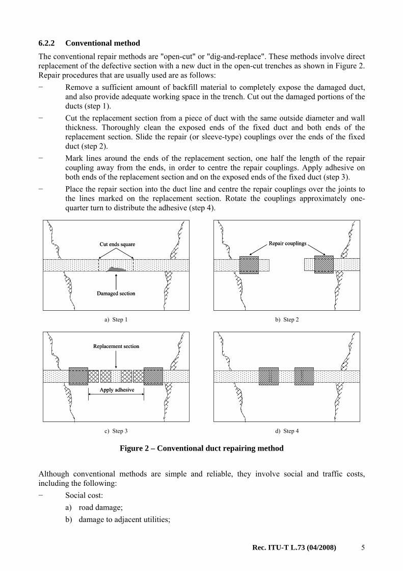
6.2.2 Conventional method The conventional repair methods are "open-cut" or "dig-and-replace". These methods involve direct replacement of the defective section with a new duct in the open-cut trenches as shown in Figure 2. Repair procedures that are usually used are as follows: − Remove a sufficient amount of backfill material to completely expose the damaged duct,
and also provide adequate working space in the trench. Cut out the damaged portions of the ducts (step 1).
− Cut the replacement section from a piece of duct with the same outside diameter and wall thickness. Thoroughly clean the exposed ends of the fixed duct and both ends of the replacement section. Slide the repair (or sleeve-type) couplings over the ends of the fixed duct (step 2).
− Mark lines around the ends of the replacement section, one half the length of the repair coupling away from the ends, in order to centre the repair couplings. Apply adhesive on both ends of the replacement section and on the exposed ends of the fixed duct (step 3).
− Place the repair section into the duct line and centre the repair couplings over the joints to the lines marked on the replacement section. Rotate the couplings approximately one-quarter turn to distribute the adhesive (step 4).
Cut ends square
Damaged section
Cut ends square
Damaged section
Repair couplingsRepair couplings
a) Step 1 b) Step 2
Replacement section
Apply adhesive
Replacement section
Apply adhesive
c) Step 3 d) Step 4
Figure 2 – Conventional duct repairing method
Although conventional methods are simple and reliable, they involve social and traffic costs, including the following: − Social cost:
a) road damage; b) damage to adjacent utilities;

6 Rec. ITU-T L.73 (04/2008)
c) damage to adjacent structures; d) noise and vibration; e) air pollution; f) vehicular traffic disruption; g) pedestrian safety; h) business loss; i) site safety; j) citizen complaints; k) environmental impact.
− Cost of vehicle or traffic disruption: a) cost of fuel; b) cost of travel time; c) road damage; d) vehicular wear.
When the costs described above are not negligible, it is recommended to use trenchless techniques.
6.2.3 High pressure water jetting The main purpose of this technique is to wash out debris or sludge, which may block a test mandrel, with a high-pressure water-jet. A nozzle for cleaning inside the duct, which is attached to high-pressure hose, is designed to be self-propelled within the duct being cleaned with the help of the reaction force of the discharged high-pressure water.
6.2.4 Method for removing irregularities or enlarging an underground duct This method re-rounds deformed sections of duct by the insertion of an expansion device. The expander system is inflated with hydraulic pressure. The device consists of a cylindrical housing corresponding approximately to the diameter of the duct, a number of expanding members and a conical wedge driven by an axial hydraulic ram. The device is drawn through the duct with its members in a retracted position, and the ram is operated to force the members outward against the wall of the duct to remove irregularities or re-round the deformed part of the duct. The members are then retracted as the device is drawn forward to the next obstruction by means of pulling force.
6.2.5 Robotic repair system A remote controlled device with CCTV monitoring is used for the localized repair of defects and obstructions using grinding tools. This system removes obstructions and intrusions and also mills out cracks to provide a good surface. The hydraulically driven grinding head can be fitted with various shapes of cutter to cope with most obstructions. The operation of these self-propelled robots is monitored by a CCTV camera attached to a head.

Rec. ITU-T L.73 (04/2008) 7
6.2.6 Re-rounder method This method can restore deflected ducts by pneumatic vibrator as shown in Figure 3. A powerful high frequency vibration consolidates and stabilizes material around the duct which corrects the deformation. The ducts must be cleaned before re-rounding and need to be relatively straight, as the device may not go through small-radius bends.
Figure 3 – Re-rounder
6.2.7 Pipe-bursting method The pipe-bursting technique is used to replace worn out gas, water or sewer pipelines that may be fractured without digging. A cone-shaped tool ("bursting head") is inserted into the existing pipe and forced through it, fracturing the pipe. At the same time, a new pipe is pulled through. The new pipe can be of the same size or larger than the replaced pipe. The rear of the bursting head is connected to the new pipe, and the front end of the bursting head is connected to a winching cable. As this method may have a detrimental effect on adjacent pipes, it is recommended that this method be applied to single duct lines, and used with caution. In addition, buried object detection is required. A typical pipe-bursting operation layout is illustrated in Figure 4.
Figure 4 – Pipe-bursting method
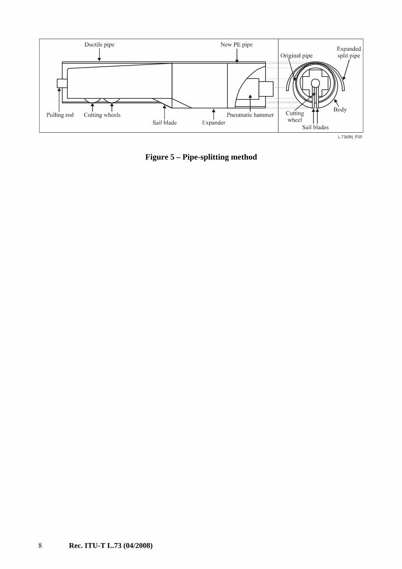
6.2.8 Pipe-splitting method Pipe splitting is a similar technique to pipe bursting but is used on non-fragmenting pipes such as steel, ductile iron or polyethylene. The technique is generally the same, but instead of the bursting head, this method uses a splitter, which cuts the existing pipe along one line on the bottom and opens it out, rather than fracturing it (see Figure 5). The splitter is pulled through the existing pipe by either a wire rope or steel rods. The splitting and opening of the existing pipe creates a hole, and the new pipe is pulled immediately behind the splitter. Like the pipe bursting method, it is recommended that this method be applied to single duct lines, with caution and using buried object detection.
8 Rec. ITU-T L.73 (04/2008)
Figure 5 – Pipe-splitting method

Rec. ITU-T L.73 (04/2008) 9
Appendix I
Korean experience (This appendix does not form an integral part of this Recommendation)
I.1 Inspection methods Figure I.1 shows various defect images that were captured by a CCTV system developed in Korea. It has been found that the pointed and oval-shaped deformations (Figure I.1c and I.1d) constitute about 60% of all plastic duct defects.
Figure I.1 – Defects in ducts
10 Rec. ITU-T L.73 (04/2008)
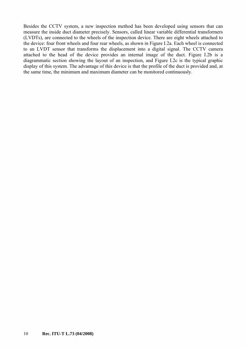
Besides the CCTV system, a new inspection method has been developed using sensors that can measure the inside duct diameter precisely. Sensors, called linear variable differential transformers (LVDTs), are connected to the wheels of the inspection device. There are eight wheels attached to the device: four front wheels and four rear wheels, as shown in Figure I.2a. Each wheel is connected to an LVDT sensor that transforms the displacement into a digital signal. The CCTV camera attached to the head of the device provides an internal image of the duct. Figure I.2b is a diagrammatic section showing the layout of an inspection, and Figure I.2c is the typical graphic display of this system. The advantage of this device is that the profile of the duct is provided and, at the same time, the minimum and maximum diameter can be monitored continuously.

Rec. ITU-T L.73 (04/2008) 11
a) Perspective view of the device
b) Layout of inspection
c) Graphic display
Figure I.2 – Duct inspection method
12 Rec. ITU-T L.73 (04/2008)
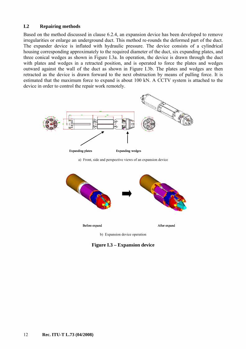
I.2 Repairing methods Based on the method discussed in clause 6.2.4, an expansion device has been developed to remove irregularities or enlarge an underground duct. This method re-rounds the deformed part of the duct. The expander device is inflated with hydraulic pressure. The device consists of a cylindrical housing corresponding approximately to the required diameter of the duct, six expanding plates, and three conical wedges as shown in Figure I.3a. In operation, the device is drawn through the duct with plates and wedges in a retracted position, and is operated to force the plates and wedges outward against the wall of the duct as shown in Figure I.3b. The plates and wedges are then retracted as the device is drawn forward to the next obstruction by means of pulling force. It is estimated that the maximum force to expand is about 100 kN. A CCTV system is attached to the device in order to control the repair work remotely.
Expanding plates Expanding wedges Expanding plates Expanding wedges a) Front, side and perspective views of an expansion device
Before expand After expand Before expand After expand b) Expansion device operation
Figure I.3 – Expansion device
Rec. ITU-T L.73 (04/2008) 13
Bibliography
[b-ITU-T Construction] ITU-T Handbook (1994), Construction, Installation, Jointing and Protection of Optical Fibre Cables.
[b-ITU-T Plant] ITU-T Handbook (1991), Outside Plant Technologies for Public Networks.
[b-Bhavani] Bhavani, S., Gangavarapu, Mohammad Najafi, and Salem, O. (2004), Quantitative Analysis and Comparison of Traffic Disruption Using Open-Cut and Trenchless Methods of Pipe Installation, North American Society for Trenchless Technology (NASTT), NO-DIG 2004, New Orleans, Louisiana.
[b-TTC 2001.02] TTC Technical Report 2001.02, Guidelines for Pipe Bursting. <http://www.ttc.latech.edu/publications/guidelines_pb_im_pr/bursting.pdf>
[b-Wirahadikusumah] Wirahadikusumah, R., Abraham, D.M., Iseley, T., and Prasanth, R.K., (1998), Assessment technologies for sewer system rehabilitation, Automation in Construction, Vol. 7, No. 4, May; pp. 259-270.
[b-Kim] Kim, H.W., and Kim, D.H. (2005), Assessment and repairing technologies for telecommunication conduit, 23rd International Conference and Exhibition, Ahoy Rotterdam, The Netherlands, September.


Printed in Switzerland Geneva, 2009
SERIES OF ITU-T RECOMMENDATIONS
Series A Organization of the work of ITU-T
Series D General tariff principles
Series E Overall network operation, telephone service, service operation and human factors
Series F Non-telephone telecommunication services
Series G Transmission systems and media, digital systems and networks
Series H Audiovisual and multimedia systems
Series I Integrated services digital network
Series J Cable networks and transmission of television, sound programme and other multimedia signals
Series K Protection against interference
Series L Construction, installation and protection of cables and other elements of outside plant
Series M Telecommunication management, including TMN and network maintenance
Series N Maintenance: international sound programme and television transmission circuits
Series O Specifications of measuring equipment
Series P Telephone transmission quality, telephone installations, local line networks
Series Q Switching and signalling
Series R Telegraph transmission
Series S Telegraph services terminal equipment
Series T Terminals for telematic services
Series U Telegraph switching
Series V Data communication over the telephone network
Series X Data networks, open system communications and security
Series Y Global information infrastructure, Internet protocol aspects and next-generation networks
Series Z Languages and general software aspects for telecommunication systems