itp11 digital process display 4-20 ma user guide · itp11. digital process display 4-20 ma. ......
TRANSCRIPT
akYtec GmbH · Vahrenwalder Str. 269 A · 30179 Hannover · Germany · Tel.: +49 (0) 511 16 59 672-0 · www.akytec.de
EN
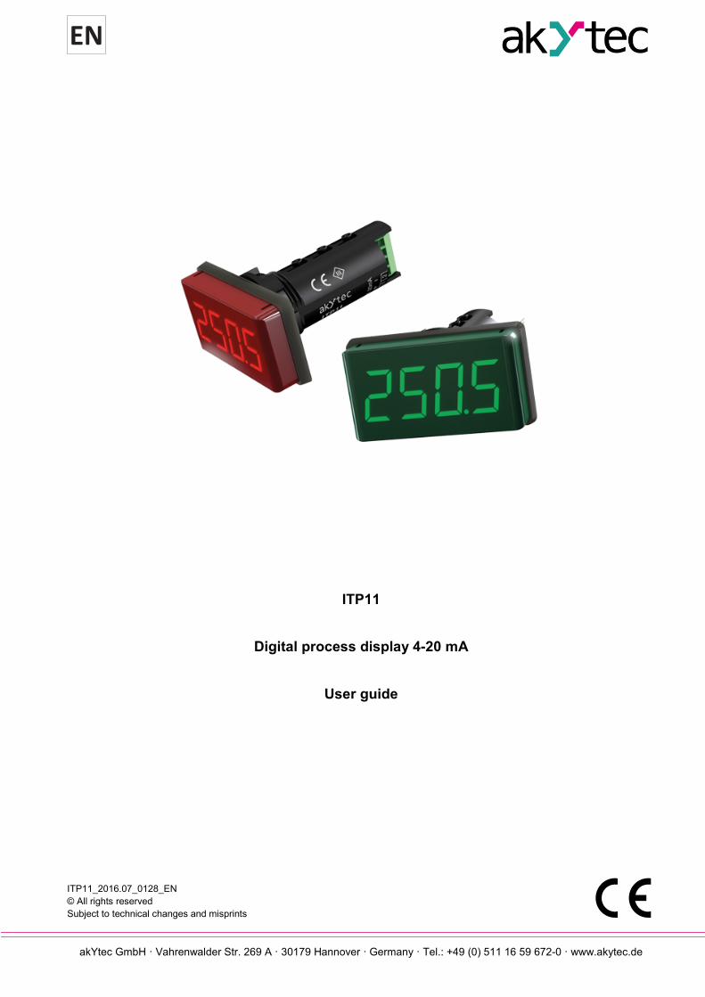
ITP11
Digital process display 4-20 mA
User guide
ITP11_2016.07_0128_EN © All rights reserved Subject to technical changes and misprints
akYtec GmbH · Vahrenwalder Str. 269 A · 30179 Hannover· Germany · Tel.: +49 (0) 511 16 59 672-0 · www.akytec.de
1
Contents
1 Safety guidelines ............................................................................................................................................ 2
2 Intended use ................................................................................................................................................... 3
3 Specifications ................................................................................................................................................. 4
4 Functional description ................................................................................................................................... 5
5 Installation and operation .............................................................................................................................. 6
5.1 Installation ................................................................................................................................................ 6
5.2 Operating mode ....................................................................................................................................... 6
5.3 Programming mode ................................................................................................................................. 8
6 Maintenance .................................................................................................................................................. 11
7 Transportation and storage ......................................................................................................................... 12
8 Scope of delivery .......................................................................................................................................... 13
Appendix A Dimensions ................................................................................................................................... 14
Appendix B Electrical connection ................................................................................................................... 15

Safety guidelines
akYtec GmbH · Vahrenwalder Str. 269 A · 30179 Hannover· Germany · Tel.: +49 (0) 511 16 59 672-0 · www.akytec.de
2
1 Safety guidelines
Please read through the user guide carefully before commissioning the device. Damages that arise from non-observance of the guidelines in the user guide shall be devoid of any liability. – The device may only be used in the manner described in this user guide. – No technical modifications may be made to the device. – The device may not be used if the environmental conditions (temperature, humidity etc.) are not within
the limits indicated in the specification. – The device may not be used in explosive areas and there may be no chemically active substances in the
air. – The device should only be cleaned with a damp cloth. No abrasives or solvent-based cleaners should be
used. Non-observance of the safety guidelines may result in damage to the device and injury to users.

Intended use
akYtec GmbH · Vahrenwalder Str. 269 A · 30179 Hannover· Germany · Tel.: +49 (0) 511 16 59 672-0 · www.akytec.de
3
2 Intended use
The ITP11 is a universally applicable, digital display unit. It is designed to be connected to any transmitter with a 4-20 mA output. The device requires no auxiliary power and is supplied directly from the measured current. The field of application of the device includes the control and monitoring of industrial processes. The display can be used in automated systems as a primary or secondary display. The device may only be operated – properly installed and – in accordance with the specification. Improper use – The ITP11 may not be used for medical devices that sustain, monitor or otherwise affect human life or
health. – The device may not be used in potentially explosive environment. – The device may not be used in an atmosphere with chemically active substances.

Specifications
akYtec GmbH · Vahrenwalder Str. 269 A · 30179 Hannover· Germany · Tel.: +49 (0) 511 16 59 672-0 · www.akytec.de
4
3 Specifications
ITP11 can be ordered in different versions. They differ in the display color. Ordering key:
Table 3.1 Technical data Supply current from current loop Input signal 4-20 mA (2-wire) Inputs 1 Measuring range 3.8…22.5 mA Normal operation 3.2…25 mA Voltage drop, max. 10 V Accuracy 0.2% + 1 digit Display LED, 7-segment display Character height 14 mm Display colour red or green Number of digits in display 4 Sampling rate (without damping) 1 reading / s IP Code front IP65, rear IP20 Dimensions 48 x 26 x 65 mm Weight approx. 30 g Protection class III Ambient temperature -30…+70 °C Storage temperature -40…+80 °C Humidity up to 80% (non-condensing)
► NOTICE Before connecting an active output of another device to the ITP11 input, ensure that the output voltage is sufficient for correct operation of the ITP11 (≥10 V).
ITP11-X
- - Display color redG - Display color green
Functional description
akYtec GmbH · Vahrenwalder Str. 269 A · 30179 Hannover· Germany · Tel.: +49 (0) 511 16 59 672-0 · www.akytec.de
5
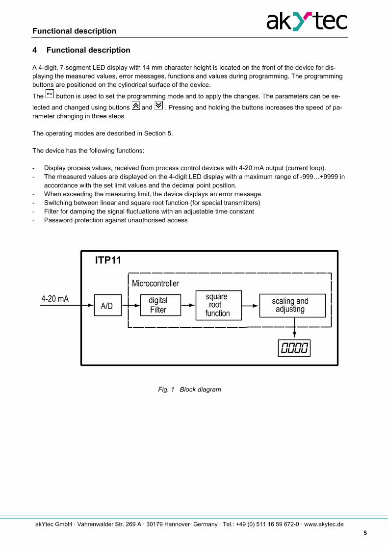
4 Functional description
A 4-digit, 7-segment LED display with 14 mm character height is located on the front of the device for dis-playing the measured values, error messages, functions and values during programming. The programming buttons are positioned on the cylindrical surface of the device.
The button is used to set the programming mode and to apply the changes. The parameters can be se-
lected and changed using buttons and . Pressing and holding the buttons increases the speed of pa-rameter changing in three steps. The operating modes are described in Section 5. The device has the following functions: - Display process values, received from process control devices with 4-20 mA output (current loop). - The measured values are displayed on the 4-digit LED display with a maximum range of -999…+9999 in
accordance with the set limit values and the decimal point position. - When exceeding the measuring limit, the device displays an error message. - Switching between linear and square root function (for special transmitters) - Filter for damping the signal fluctuations with an adjustable time constant - Password protection against unauthorised access
Fig. 1 Block diagram
Installation and operation
akYtec GmbH · Vahrenwalder Str. 269 A · 30179 Hannover· Germany · Tel.: +49 (0) 511 16 59 672-0 · www.akytec.de
6
5 Installation and operation
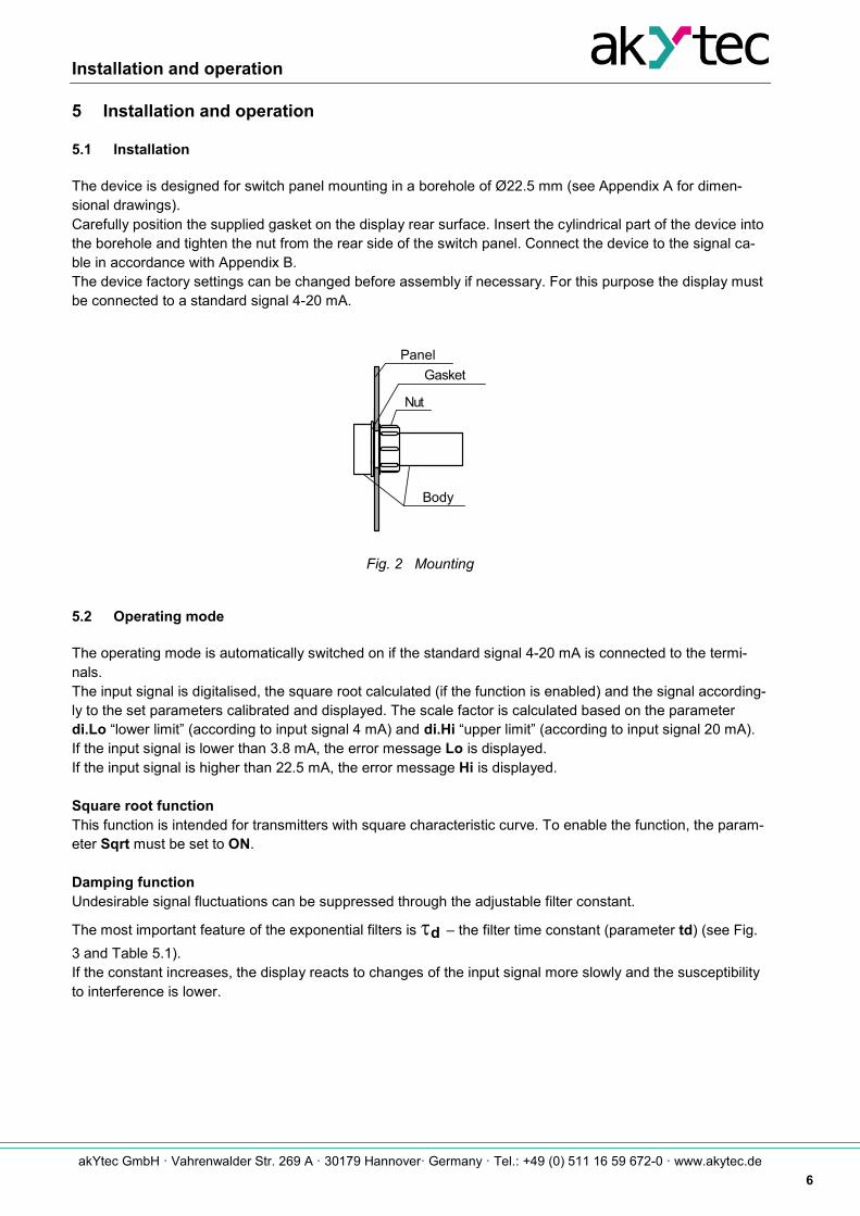
5.1 Installation
The device is designed for switch panel mounting in a borehole of Ø22.5 mm (see Appendix A for dimen-sional drawings). Carefully position the supplied gasket on the display rear surface. Insert the cylindrical part of the device into the borehole and tighten the nut from the rear side of the switch panel. Connect the device to the signal ca-ble in accordance with Appendix B. The device factory settings can be changed before assembly if necessary. For this purpose the display must be connected to a standard signal 4-20 mA.
Fig. 2 Mounting
5.2 Operating mode
The operating mode is automatically switched on if the standard signal 4-20 mA is connected to the termi-nals. The input signal is digitalised, the square root calculated (if the function is enabled) and the signal according-ly to the set parameters calibrated and displayed. The scale factor is calculated based on the parameter di.Lo “lower limit” (according to input signal 4 mA) and di.Hi “upper limit” (according to input signal 20 mA). If the input signal is lower than 3.8 mA, the error message Lo is displayed. If the input signal is higher than 22.5 mA, the error message Hi is displayed. Square root function This function is intended for transmitters with square characteristic curve. To enable the function, the param-eter Sqrt must be set to ON. Damping function Undesirable signal fluctuations can be suppressed through the adjustable filter constant.
The most important feature of the exponential filters is τd – the filter time constant (parameter td) (see Fig. 3 and Table 5.1). If the constant increases, the display reacts to changes of the input signal more slowly and the susceptibility to interference is lower.
PanelGasket
Nut
Body

Installation and operation
akYtec GmbH · Vahrenwalder Str. 269 A · 30179 Hannover· Germany · Tel.: +49 (0) 511 16 59 672-0 · www.akytec.de
7
Fig. 3
t i
( signal jump d = 0 s )
= 1 s )d
I
I
0,63 I
0t, s
( damped signal
I
II
III = 3 s )d( damped signal
Installation and operation
akYtec GmbH · Vahrenwalder Str. 269 A · 30179 Hannover· Germany · Tel.: +49 (0) 511 16 59 672-0 · www.akytec.de
8
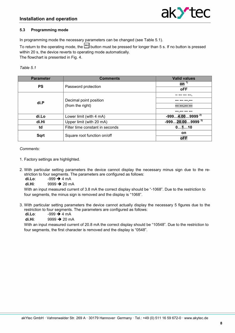
5.3 Programming mode
In programming mode the necessary parameters can be changed (see Table 5.1).
To return to the operating mode, the button must be pressed for longer than 5 s. If no button is pressed within 20 s, the device reverts to operating mode automatically. The flowchart is presented in Fig. 4. Table 5.1
Parameter Comments Valid values
PS Password protection on 1) oFF
di.P Decimal point position (from the right)
– -– -– -–. -– -– -–.-– -– -–.-– -– -–.-– -– -–
di.Lo Lower limit (with 4 mA) -999…4.00…9999 2) di.Hi Upper limit (with 20 mA) -999…20.00…9999 3)
td Filter time constant in seconds 0…1…10
Sqrt Square root function on/off on
oFF Comments: 1. Factory settings are highlighted. 2. With particular setting parameters the device cannot display the necessary minus sign due to the re-
striction to four segments. The parameters are configured as follows: di.Lo: -999 è 4 mA di.Hi: 9999 è 20 mA With an input measured current of 3.8 mA the correct display should be “-1068”. Due to the restriction to four segments, the minus sign is removed and the display is “1068”.
3. With particular setting parameters the device cannot actually display the necessary 5 figures due to the
restriction to four segments. The parameters are configured as follows: di.Lo: -999 è 4 mA di.Hi: 9999 è 20 mA With an input measured current of 20.8 mA the correct display should be “10548”. Due to the restriction to four segments, the first character is removed and the display is “0548”.
Installation and operation
akYtec GmbH · Vahrenwalder Str. 269 A · 30179 Hannover· Germany · Tel.: +49 (0) 511 16 59 672-0 · www.akytec.de
9
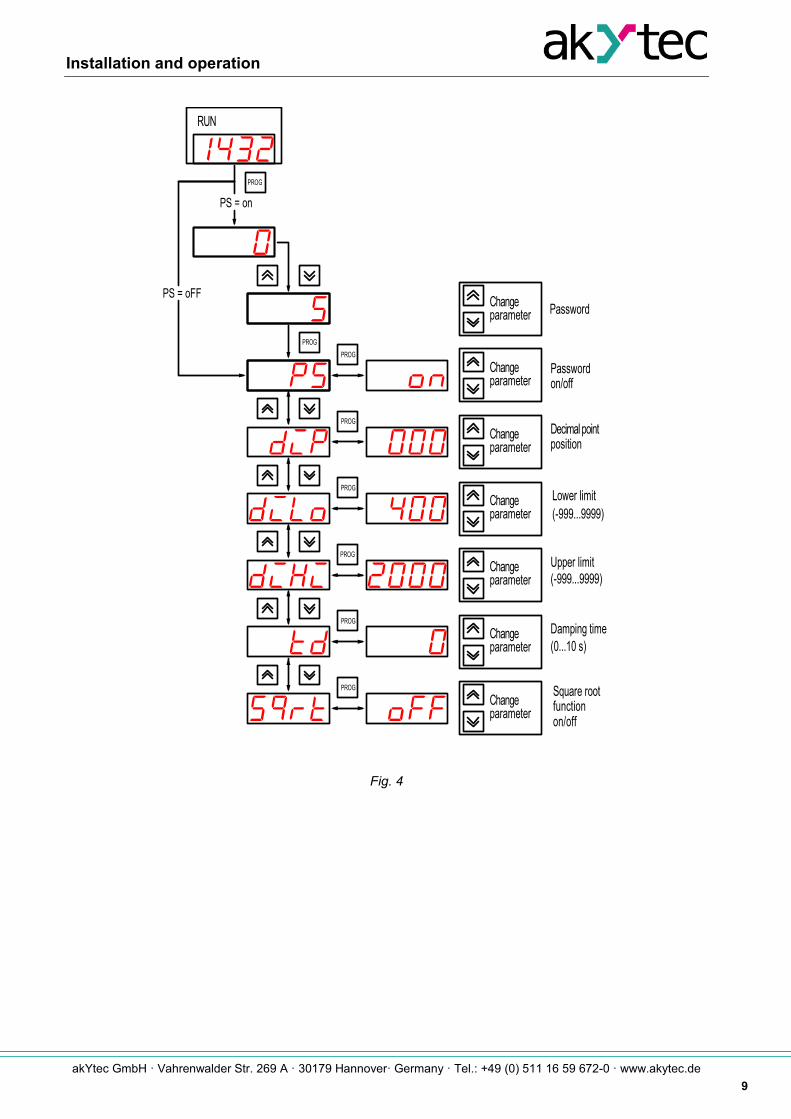
Fig. 4
PROG
PROG
PROG
PROG
RUN
Decimal pointposition
Lower limit(-999...9999)
(-999...9999)Upper limit
Damping time(0...10 s)
PROG
PROG
functionSquare root
PROG
Passwordon/off
parameterChange
PROG
PasswordPS = oFF
PS = on
parameterChange
parameterChange
parameterChange
parameterChange
parameterChange
parameterChange
on/off

Installation and operation
akYtec GmbH · Vahrenwalder Str. 269 A · 30179 Hannover· Germany · Tel.: +49 (0) 511 16 59 672-0 · www.akytec.de
10
To enter the programming mode use the button .
To scroll the parameters use the buttons and , to change the parameter use the button . When the device is switched on for the first time or the password protection is activated, 0 is displayed.
Use the buttons and to enter the correct password (factory setting – 5), then press the button to confirm. If an incorrect password is entered, the device reverts to operating mode. If the password protection is disabled (the parameter PS is oFF), the password is not requested. If the button is pressed while the parameter PS is being displayed, the following characters appear on the display: I- - - - . This means that the upper end of the menu has been reached.
If the button is pressed while the parameter Sqrt is being displayed, the following characters appear on the display: - - - -I. This means that the lower end of the menu has been reached.
Briefly push the button (< 1 s) to change the selected parameter. The display indicates the actual param-eter value. The factory settings are shown in Fig. 4 and Table 2. The value can be changed using buttons
and . After confirming by pressing the button, you return to the parameter list. Potential errors and troubleshooting measures are listed in Table 5.2. Table 5.2 Error display
Display Possible cause of error Remedy
Lo Input current lower than 3.8 mA Check input signal
Hi Input current higher than 22.5 mA Check input signal
None No input signal Check input signal
Reverse polarity on input Check polarity
Maintenance
akYtec GmbH · Vahrenwalder Str. 269 A · 30179 Hannover· Germany · Tel.: +49 (0) 511 16 59 672-0 · www.akytec.de
11
6 Maintenance
The maintenance includes: – cleaning the housing and the terminals from dust, dirt and debris – checking the fastening of the device – checking the wiring (connecting leads, fastenings, mechanical damage) The device should be cleaned with a damp cloth only. No abrasives or solvent-containing cleaners may be used. The safety guidelines in Section 1 must be observed when carrying out maintenance.
Transportation and storage
akYtec GmbH · Vahrenwalder Str. 269 A · 30179 Hannover· Germany · Tel.: +49 (0) 511 16 59 672-0 · www.akytec.de
12
7 Transportation and storage
Pack the device in such a way as to protect it reliably against impact for storage and transportation. The original packaging provides optimum protection. If the device is not taken immediately after delivery into operation, it must be carefully stored at a protected location. The device should not be stored in an atmosphere with chemically active substances. Storage temperature range: -40…+80 °C
► NOTICE The device may have been damaged during transportation. Check the device for transport damage and completeness! Report the transport damage immediately to the shipper and akYtec GmbH!
Scope of delivery
akYtec GmbH · Vahrenwalder Str. 269 A · 30179 Hannover· Germany · Tel.: +49 (0) 511 16 59 672-0 · www.akytec.de
13
8 Scope of delivery
– Digital process display ITP11 1 – Gasket 1 – Mounting nut 1 – User guide 1

Appendix A Dimensions
akYtec GmbH · Vahrenwalder Str. 269 A · 30179 Hannover· Germany · Tel.: +49 (0) 511 16 59 672-0 · www.akytec.de
14
Appendix A Dimensions
Fig. A.1
To prevent the device spinning, the borehole in the front panel must correspond to the dimensions in Fig. A.2.
Fig. A.2.
PROG
26
4810
65
Appendix B Electrical connection
akYtec GmbH · Vahrenwalder Str. 269 A · 30179 Hannover· Germany · Tel.: +49 (0) 511 16 59 672-0 · www.akytec.de
15
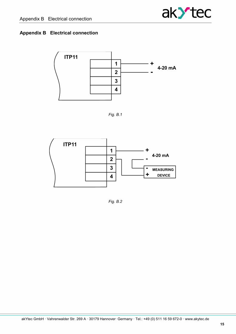
Appendix B Electrical connection
Fig. B.1
Fig. B.2
1234
4-20 mA+
ITP11
-
1234
MEASURING
4-20 mА+
+
ITP11
--
DEVICE