itp materials: a case study of chemical vapor deposition (cvd
TRANSCRIPT

RRAANNDDIndustrial Materials for the Future RampD Strategies
A Case Study of Chemical Vapor Deposition (CVD) Methods ndashApplying Low-E Coatings to Flat Glass for Applications in Sunbelt Locations
CVD
prepared by
David R Howell Richard Silberglitt
RAND Arlington Virginia
and
Douglas Norland National Renewable Energy Laboratory
Washington DC
prepared for
Industrial Materials for the Future ProgramOffice of Industrial Technologies
US Department of Energy
October 2002
NREL RAND 901 D Street SW Suite 930 1200 South Hayes Street Washington DC 20024-2157 Arlington VA 22202-5050 (202) 646-5050 (703) 413-1100 Operated for the US Department of Energy Main Offices (310) 393-0411 by Midwest Research Institute bull Battelle bull Bechtel 1700 Main Street PO Box 2138
Santa Monica CA 90407-2138
Table of Contents
List of Figures 2List of Tables 2List of Acronyms 310 Introduction 420 US Glass Industry 6
21 Sectors of the Glass Industry 6 22 Flat Glass Sector 7
30 Window Performance and Building Energy Use 831 U-Factor and R-Value 8 32 Solar Heat Gain Coefficient (SHGC) and Shading Coefficient 9 33 Visible Transmittance (VT) 9 34 Air Leakage (AL) 10 35 Designing Windows to Attain a Desired Performance Profile 11
351 Low-emissivity (Low-E) Coatings on Flat Glass 11 352 Types of Low-E Coatings 12
40 Low-E Coating Deposition Techniques 1341 Float Glass Process 13 42 Batch-sputtering Techniques 14 43 Chemical Vapor Deposition (CVD) Techniques 14
50 Comparison of Pyrolytic (CVD) and Sputtered Coatings 1551 Materials Properties 15
511 Materials Properties of Sputtered Coatings 15 512 Materials Properties of Pyrolytic Coatings 15
52 Production Benefits and Costs 15 521 Production Benefits and Costs of Sputtered Coatings 15
53 Consumer Benefits and Costs 17 531 Consumer Benefits and Costs of Sputtered Coatings 17 532 Consumer Benefits and Costs of Pyrolytic Coatings 17
60 Description of RampD on CVD Methods for Applying Pyrolytic (Low-E) Coatings to Glass 19
61 Storage Issues ndash Long-term Precursor Stability 20 611 Theoretical Calculations of Indium Compound Bond Energies 21 612 Empirical Measurement of Indium Compound Bond Energies 22
62 Gas-phase Kinetics 24 621 Deposition Rate of Indium-containing Precursors 24 622 Reaction of Precursors during Mixing 25
63 Reaction Byproducts ndash Waste Cleanup 25 70 Benefits Analysis ndash Advanced Manufacturing Using Chemical Vapor Deposition Technology for e-Windows Coatings 26
71 Analysis Assumptions and Data 27
- 1 -
List of Figures
Figure 1 Distribution of Energy Consumption in the US Glass Industry 7 Thermal Transmission of Windows ndash U-factor and R-value 8Figure 2 Solar Heat Gain of Windows ndash SHGC 9Figure 3
Figure 4 Visible Light Transmittance of Windows ndash VT 10 Figure 5 Air Leakage of Windows ndash AL 10
Climatic Zones of the Continental United States 11Figure 6 Float Glass Process 13Figure 7
Figure 8 Chemical Vapor Deposition Process 14 Figure 9 Differences Between Benefits and Costs of Pyrolytic and Sputtered Coatings18 Figure 10 Solar Spectrum 20 Figure 11 TMI Presence vs Time for Various Temperatures 23 Figure 12 Annual and Cumulative Energy Savings from Use of Pyrolytic Glass in
Southern Regions of the United States 2001-2030 28
List of Tables
Table 1 US Glass Industry Sectors and Products 6 Table 2 Summary of 1999 Glass Industry Statistics 6 Table 3 Bond Energies in Group-III Compounds (kcal mol-1) 22
- 2 -
List of Acronyms
AIM Advanced Industrial Materials Program AL Air leakage CVD Chemical vapor deposition DMIC Dimethylindium chloride DOE US Department of Energy HTFR High-temperature flow reactor HVAC Heating ventilation and air-conditioning IMF Industrial Materials for the Future Program ITO Indium tin oxide LOF Libbey-Owens-Ford Low-E Low-emissivity NREL National Renewable Energy Laboratory OIT Office of Industrial Technologies RampD Research and development SHGC Solar heat gain coefficient SNL Sandia National Laboratory TMI Trimethylindium UV Ultraviolet VT Visible transmittance
- 3 -
10 Introduction
This report describes a case study performed by RAND and NREL of government-industry research and development (RampD) aimed at designing new coating methods for the US glass industry While the project achieved substantial production benefits and energy savings the impact on the energy efficiency of buildings when the newly developed coatings are installed in windows far outweighs production energy savings
The RampD described in this report was performed by Sandia National Laboratory (SNL) and sponsored by the Industrial Materials for the Future (IMF) program ndash the successor to the Advanced Industrial Materials (AIM) program ndash of the US Department of Energy (DOE) Office of Industrial Technologies (OIT) In addition a CRADA was established with glass manufacturer and co-sponsor of the RampD project Libbey-Owens-Ford (LOF) to develop new processes at pilot and manufacturing scales
The principal problem addressed by this effort was developing methods to apply low-emissivity (or low-E) coatings by chemical vapor deposition (CVD) Low-E coatings reduce the thermal transmission through glass in windows These coatings have been particularly successful in heating-dominated climates such as those found in the northern US because they reduce heat loss from the window However in cooling-dominated climates such as those found in the southern US low-E coatings made via CVD methods (also referred to as pyrolytic coatings) did not achieve high performance characteristics because they (the coatings) transmitted escalated quantities of solar heat The next best alternative to a pyrolytic coating is a sputtered coating however sputtered coatings must be installed in a double-pane system which is not typically used in cooling-dominated climates Thus there was a lack of high-performance windows to accommodate cooling-dominated climates
Chemical vapor deposition is a process whereby a gas (the precursor) is dispersed on a layer of molten glass in the production line The subsequent chemical reactions create a new chemical structure on the surface of the glass which is the coating
The RampD team at SNL examined alternate CVD chemistries in an effort to create a low-E coating with reduced solar heat transmittance In particular the project RampD team had to determine the stability of a potential precursor gas Previous examinations of this particular precursor yielded questionable results which led some to believe that the precursor would be unstable The RampD team at SNL determined through theoretical calculations experimental measurement and numerical simulation that the previously suggested chemistry profile of the precursor gas was incorrect Under the newly discovered chemistry profile the RampD team determined that the precursor gas would be stable under the service environment
The RampD team also needed to examine potential reactions that the precursor might undergo with additives used in glass manufacturing and determine if the growth rate would be sufficient to accommodate integration into an on-line float glass coating process
- 4 -
The chemical vapor deposition methods project resulted in a methodology for developing a CVD process Coatings produced by this method can be used in cooling-dominated climates to achieve increased energy efficiency To achieve a reduced solar heat transmittance the coating blocks the near infrared and ultraviolet portions of the solar spectrum allowing only primarily visible light to transmit This is known as a spectrally selective coating In addition the pyrolytic coating developed was color neutral allowing the glass to be used in residential windows
When the newly developed coatings are installed in windows in cooling-dominated climates our benefits analysis estimates that this technology could save a cumulative 167 trillion Btu through 2030
The balance of this report is organized as follows Chapter 2 provides a brief overview of the glass industry explaining why the flat glass sector is critical to energy efficiency Chapter 3 describes how window performance can be measured and introduces the two primary types of coatings Chapter 4 briefly outlines the manufacturing processes to apply coatings to glass Chapter 5 examines the differences between the two primary types of coating with respect to materials properties benefits and costs to the producer and benefits and costs to the consumer Chapter 6 describes the RampD approach that developed a method to apply coatings by CVD Chapter 7 presents the estimated benefits of using the technologies enabled by the RampD
- 5 -
20 US Glass Industry
21 Sectors of the Glass Industry This report describes a case study performed by RAND and NREL of government funding for research and development aimed at meeting industrial process challenges faced in the flat glass sector of the glass industry The US glass industry consists of the following five sectors (1) flat glass (also referred to as float glass) (2) container glass (3) pressedblown glass (4) mineral wool glass and (5) purchased glass products Table 1 shows these sectors and some of the products manufactured by each sector1
Table 1 US Glass Industry Sectors and Products Glass Industry
Flat Glass Container Glass
PressedBlown Glass (specialty)
Mineral Wool Glass Glass
Products
Purchased
Windows
Beverage containers (beer wine liquor and
others)
Cookware Building batts Aquariums
Vehicle windshields Food containers Light bulbstubes
Industrial amp appliance insulation
Table tops
Mirrors Textile fiber Acoustical insulation Lab apparatus
Table 2 summarizes statistics associated with each sector of the glass industry The glass industry has an unfavorable balance of trade due to large imports in the container and specialty (pressedblown) sectors
Table 2 Summary of 1999 Glass Industry Statistics2
Sector Shipments ($million)
Production (short tons)
Exports ($million)
Imports ($million) Establishments Employees
(1000)
Production Wages ($hr)
Capital Expenses ($million)
Flat 2746 5000521 788 576 36 11053 2176 3227 Container 4215 9586500 174 586 61 19220 2005 3493 PressedBlown 5787 2484182 1298 2038 515 35013 1574 6368 Mineral Wool 4844 3040000 360 251 298 22823 1712 2858 Purchased Glass Products 10847 NA 1157 1047 1657 62405 1279 NA
Industry Total 28439 20111203 3777 4498 2567 150514 1749 15946
The glass industry is one of the nine most energy intensive industries consuming approximately 340 trillion Btu per year Figure 1 shows the distribution of energy consumption in the glass industry among the four major sectors
1 Energy and Environmental Profile of the US Glass Industry US Department of Energy Office of Industrial Technologies April 2002 Available at httpwwwoitdoegovglassprofileshtml 2 Energy and Environmental Profile of the US Glass Industry op cit
- 6 -
Figure 1 Distribution of Energy Consumption in the US Glass Industry3
Mineral Wool 759 TBtu
22
PressedBlown 859 TBtu
25
Flat 624 Tbtu
18
Container 1142 Tbtu
35
22 Flat Glass Sector Figure 1 shows that the flat glass sector is the least energy-intensive sector of the US glass industry with respect to energy consumption related to manufacturing However the flat glass sector has a large impact on US energy consumption because flat glass is widely used in building structures from residential homes to skyscrapers Approximately 5 of US energy consumption can be attributed to windows in residential and nonresidential buildings Additionally lighting systems account for approximately 5 of US energy consumption4 By providing consumers with high-performance windows the flat glass sector can increase the energy efficiency of buildings
While the flat glass sector is the least energy-intensive manufacturing sector of the glass industry it can have a large impact on US energy consumption because its products (windows) play a key role in determining the energy efficiency of buildings
Consumers have a wide variety of glass products from which to choose each with different performance characteristics The type of glass chosen by consumers can strongly influence the energy efficiency of buildings The performance of a particular type of glass used in a window is dependent on the climate in which the window will be installed Thus it is important to first consider the type of climate in which a window will be required to perform before one can determine an ideal suite of performance characteristics The following section describes how window performance can be measured and how the climate in which the window is used impacts which characteristics are most important to determining the energy efficiency of the window
3 Ibid 4 Selkowitz Stephen Window Performance and Building Energy Uses American Institute of Physics Conference Proceedings Number 135 1985 ISBN 0-88318-334-X
- 7 -
30 Window Performance and Building Energy Use
Window performance is crucial to a buildingrsquos energy efficiency Approximately 30 to 40 of building energy consumption is associated with heating ventilation and air-conditioning (HVAC) and lighting systems5 Selkowitz defines six primary factors that affect window energy performance6
1) Thermal transmission 2) Light transmission 3) Control of solar heat gain 4) Infiltration 5) Ventilation 6) Condensation
Several measurable quantities that determine the energy efficiency of a window are discussed in the following sections
31 U-Factor and R-Value The U-factor is a measure of rate of thermal heat transfer through a window As the U-factor decreases the rate of thermal heat transfer also decreases It is measured in units of energy per unit of time area and temperature (eg Btuhr-ft2-degF) The inverse of the U-factor is known as the R-value The R-value indicates the insulating value of the window Thus as a window transfers less heat the R-value increases In colder heating-dominated climates the U-factor and the R-value are critical to the energy performance of a window However in cooling-dominated climates the U-factor and the R-value are not as critical
Figure 2 Thermal Transmission of Windows ndash U-factor and R-value7
Increased heat flow darr
Higher U-factor darr
Lower R-value
5 Spectrally Selective Glazings Federal Technology Alert August 1998 DOEEE-0173 6 Selkowitz Stephen Window Performance and Building Energy Uses op cit7 Figure taken from Efficient Windows Collaborative Available at httpwwwefficientwindowsorgselection2html
- 8 -
32 Solar Heat Gain Coefficient (SHGC) and Shading Coefficient The solar heat gain coefficient is the percentage of the solar energy that enters a building through the window As the SHGC increases the amount of heat transfer into the building from sunlight increases Another quantity used to measure this characteristic of window performance is the shading coefficient The shading coefficient is a measure of the amount of solar energy transferred through the glass As the shading coefficient increases the amount of energy transferred through the window from sunlight increases The SHGC (or shading coefficient) is the most important characteristic of a window for cooling-dominated climates such as are found in Sunbelt locations
Figure 3 Solar Heat Gain of Windows ndash SHGC8
Increased transfer of solar energy
darr Higher SHGC
darr Higher shading
coefficient
33 Visible Transmittance (VT) Visible transmittance (VT) is a measure of the amount of visible light that is transmitted through a window As VT increases the amount of visible light transmitted through the window increases VT is important when considering the energy efficiency of a building because it can reduce the load on electric lighting systems during the day As a building has more sunlight transmitted occupants may not rely as strongly on electric lights thus reducing energy consumption
8 Ibid
- 9 -
Figure 4 Visible Light Transmittance of Windows ndash VT9
More visible light transmitted
darr Higher VT
34 Air Leakage (AL) Air leakage (AL) is a measure of the flow rate of air through gaps in the window assembly As the flow of air between the interior and the exterior increases the AL increases AL is measured in volume of air per area of window Although AL does play a role in the energy performance of a building it is not as critical as the U-factor or the SHGC
Figure 5 Air Leakage of Windows ndash AL10
Increased air flow between interior and exterior
darr Higher AL
9 Ibid 10 Ibid
- 10 -
35 Designing Windows to Attain a Desired Performance Profile 351 Low-emissivity (Low-E) Coatings on Flat Glass Glass manufacturers are able to design window systems to achieve a more ideal performance profile in a particular climate The U-factor and the SHGC are crucial parameters in evaluating the energy efficiency of a window both characteristics have a direct impact on performance Visible light transmittance indirectly affects the energy efficiency of a window An increase in visible light transmittance can reduce energy consumption by providing more daylight reducing the demand on electric lighting systems
Glass manufacturers will often use coatings to tailor the performance characteristics of a window Low-emissivity also known as low-E coatings are used primarily to lower the U-factor of a window Thus low-E windows act as better thermal insulators between the inside and outside environments Low-E coatings consist of a thin film that lies on the surface of the glass and changes the optical properties of the glass They were introduced commercially in 1982 and now account for more than 40 of all residential windows11
The characteristics of low-E coatings make them ideal for use in northern heating-dominated climates Low-E coatings reduce the thermal transmission through the window thus reducing demand on heating systems Figure 6 is a map of the continental US showing the different climatic zones
Figure 6 Climatic Zones of the Continental United States12
Northern ndash Heating-dominated Zone
Central ndash Heating and Cooling Zone
Southern ndash Cooling-dominated Zone
Before the IMF glass coatings projects low-E coatings typically had a large SHGC Thus low-E coatings could not be used in southern cooling dominated climates because the window would allow too much solar energy to be transmitted through the window In cooling-dominated climates ndash also referred to as ldquoSunbeltrdquo locations (the southern third
11 Selkowitz SE et al Building Technologies Program 1994 Annual Report Windows and DaylightingEnergy amp Environment Division Lawrence Berkeley National Laboratory LBL-36553 Available athttpeandelblgovBTPpubannrep94annrep94html 12 Figure taken from Efficient Windows Collaborative Available at httpwwwefficientwindowsorgselection2html
- 11 -
of the US) ndash control of solar heat gain is the dominant characteristic that determines energy performance of windows Decreased solar heat gain lowers the demand on cooling systems
For cooling-dominated climates such as Sunbelt locations low-E coatings can be beneficial if the SHGC can be minimized
352 Types of Low-E Coatings There are two primary techniques used to deposit low-E coatings onto flat glass (1) batch sputtering and (2) chemical vapor deposition (CVD)
Batch sputtering is the traditional technique used to apply coatings to glass However batch-sputtering cannot be used in a single-glaze window system The majority of windows in cooling-dominated climates use single-glaze windows Therefore sputtered coatings do not have extensive applicability in Sunbelt locations
Low-E coatings applied using CVD methods are often referred to as pyrolytic coatings Pyrolytic coatings can be used in single-glaze window systems However prior to the IMF-funded chemical vapor deposition methods project pyrolytic coatings had a high SHGC To overcome this problem the optical properties of the coatings were tailored such that the near infrared and ultraviolet portions of the solar spectrum are reflected while the visible portions of the spectrum are transmitted This arrangement allows for greater transmittance of visible light while blocking energy-bearing light from the invisible portions of the solar spectrum Low-E coatings that transmit and block particular portions of the solar spectrum are called spectrally-selective coatings In addition to accommodate the broadest range of applications an ideal coating would be color neutral Since residential homes typically use color-neutral windows a coating that is invisible to the naked eye can be applied more broadly
A result of the IMF-funded chemical vapor deposition methods project was a CVD method to apply pyrolytic coatings to glass for use in Sunbelt locations To accomplish this end a pyrolytic coating that has a low SHGC and is color neutral was necessary
Section 5 will discuss the differences between the coatings mentioned here in more detail The following section discusses the differences between the batch-sputtering and CVD coating techniques
- 12 -
40 Low-E Coating Deposition Techniques
41 Float Glass Process The float glass process was developed by the Pilkington brothers in the 1950s This process revolutionized the flat glass sector replacing previous processes that were more energy intensive13
In the float glass process molten glass at a temperature of approximately 1950degF (1065degC) comes from the furnace and is fed onto a pool of molten tin (sometimes referred to as the float or tin bath) The float bath can be 160 ndash 190 feet (49 ndash 58 m) long and 12 ndash 30 feet (37 ndash 91 m) wide As the molten glass reaches the pool of molten tin the glass spreads uniformly across the bottom layer of tin The molten glass then begins to cool while its surface conforms to match that of the uniform molten tin The result is a glass with a smooth surface of uniform thickness and without distortion The molten glass exits the float bath at a temperature of approximately 1125degF (600degC)14
After exiting the float bath the molten glass enters the annealing lehr The annealing lehr is used to relieve any stresses that may have been created on the surface of the glass during forming After it is annealed the glass is slowly cooled to room temperature and then cut15
Figure 7 shows a schematic of the float glass process
Figure 7 Float Glass Process16
13 Energy and Environmental Profile of the US Glass Industry op cit 14 Ibid 15 Ibid 16 Figure taken from Energy and Environmental Profile of the US Glass Industry op cit
- 13 -
42 Batch-sputtering Techniques Coatings applied using batch-sputtering techniques are completed after the glass has come off the production line Additionally glass is sputtered-coated after production and after the glass has been tempered and cut into its final form Thus batch sputtering is an off-line process This is the traditional method used to deposit coatings on glass hence batch sputtering can be used to apply a wide variety of coatings to glass
Batch sputtering is performed in a vacuum chamber where an ion beam hits a target The subsequent reaction causes molecules of the target to fall and deposit on the surface of the glass Sputtering occurs at low temperatures relative to CVD methods Sputtered coatings are sometimes referred to as lsquosoftrsquo coatings because they require special care to assure that the coatings are not damaged during handling17
43 Chemical Vapor Deposition (CVD) Techniques Coatings applied using chemical vapor deposition (CVD) techniques are produced during the float glass process on the float glass line Hence applying coatings by CVD is an onshyline process CVD methods can be employed in the float glass process in three locations
(1) in the float bath (750 ndash 600degC) (2) in between the float bath and the annealing lehr (600 ndash 570degC) or (3) in the annealing lehr after the annealing zone (lt500degC)18
Coatings applied using CVD methods are commonly referred to as pyrolytic coatings CVD methods involve reacting a precursor gas with the hot surface of the glass on the float line As a result of this chemical reaction the surface of the glass takes on a new chemical structure This coating is sometimes referred to as a lsquohardrsquo coating because the coating becomes part of the surface of the glass and is thus more durable than sputtered coatings The reactions must occur very quickly to avoid slowing down the float line A line carrying a twelve-foot wide ribbon of glass might move at approximately one foot per second19 In addition the CVD process must be integrated into the float line without disrupting the float glass process Figure 8 shows a schematic of the CVD process
The following section discusses the differences between pyrolytic and sputtered coatings
Figure 8 Chemical Vapor Deposition Process
Hot Glass Hard Coating
Reactive Gas
17 Coatings on Glass Technology Roadmap Workshop (September 2000) Sandia National LaboratoriesLivermore CA Available at httpwwwcasandiagovCRF03_Reports04_GlassCoatings 18 McCurdy Richard J Successful Implementation Methods of Atmospheric CVD on a GlassManufacturing Line Thin Solid Films vol 351 (1999) pp 66 ndash 72 19 Coatings on Glass Technology Roadmap Workshop op cit
- 14 -
50 Comparison of Pyrolytic (CVD) and Sputtered Coatings
Low-emissivity (low-E) coatings are applied flat glass to in architectural applications to reduce the amount of solar heat transmitted through windows Differences between pyrolytic and sputtered coatings can be separated into three distinct categories as follows
1) Materials properties 2) Production benefits and costs 3) Consumer benefits and costs
51 Materials Properties 511 Materials Properties of Sputtered Coatings Sputtered glass is produced by depositing silver and oxide multi-layers onto the glass after production Sputtered coatings are applied at low temperatures as compared to pyrolytic coatings (produced by CVD) Thus sputtered coatings are multiple layers (typically 9 ndash 12 layers) of metal oxides adhering to the surface of the glass
512 Materials Properties of Pyrolytic Coatings Pyrolytic coatings are produced using the chemical vapor deposition (CVD) method whereby metal oxides are deposited onto the surface of the glass during production while the glass is still in a molten state Pyrolytic coatings are applied to molten glass at temperatures of approximately 600 - 700degC20 Thus pyrolytic coatings become part of the glass rather than a layer deposited on the glass surface
52 Production Benefits and Costs 521 Production Benefits and Costs of Sputtered Coatings21
Sputtered coatings are applied off-line in a vacuum chamber by hitting a target metal with an ion beam to deposit the resultant ions onto the glass forming a thin film Coatings are applied in multiple layers Batch-sputtering techniques offer several benefits
(1) Batch sputtering is the traditional technique used to deposit coatings on glass thus there is a well-established understanding of a wide variety of candidate materials that can be used to form a coating
(2) Processes necessary to apply and handle coatings are well-established (3) Performance properties of sputtered glass are superior to pyrolytic glass
(produced using CVD) for many applications
There are several drawbacks of applying coatings using sputtering techniques (1) Applying coatings off-line requires additional processes and time In addition
coatings must be deposited in a vacuum chamber (2) Since the coating is applied as a layer on top of the glass sputtered glass requires
special handling to avoid scratches before installation thus promoting longer lead times The scratch susceptibility of sputtered glass has caused some to refer to it as lsquosoft coatedrsquo
20 Coatings on Glass Technology Roadmap Workshop op cit21 Gore Paul (Pilkington North America Toledo OH) Pyrolytic low-E = Sputtered low-E DifferentProcess = Different Benefits Viewed on September 17 2002 athttpwwwdoorandwindowmakercomfall202000pyrolytic20low-Ehtm
- 15 -
(3) Sputtered coatings tend to be more sensitive to moisture in the air This factor limits a sputtered coatingrsquos shelf life Therefore producers must carefully consider the length of time between sputtering and installation to avoid loss of stocks Once installed however the coating is insulated in a double pane from damage due to moisture Thus glass may not be sputtered until the consumer has placed an order for the glass promoting longer lead times
(4) Not all sputtered glass can be tempered Those that can be tempered cannot be tempered under normal tempering conditions In addition annealed and tempered glass used in the same application may display differences in appearance
(5) Most manufacturers of sputtered glass suggest that coatings on the edge of the glass be deleted This creates additional processes requiring time and equipment
522 Production Benefits and Costs of Pyrolytic Coatings22 23
Pyrolytic coatings are produced by applying the coating via chemical vapor deposition (CVD) This process is done on the production line when semi-molten glass is exiting the float tin bath As the semi-molten glass comes off the floattin bath a chemical vapor is sprayed onto the surface of the glass A chemical reaction occurs between the vapor and the glass surface changing the chemical composition of the glass surface resulting in a coating that strongly adheres to the glass
Application of coatings by CVD offers several benefits (1) Since the deposition of coatings is done on-line CVD offers excellent lead times (2) The coatings become a part of the glass rather than a layer on the surface of the
glass increasing their resistance to scratches This eliminates the need for special handling and thus decreases lead times The scratch resistance of pyrolytic coatings has caused some to refer to it as lsquohard coatedrsquo
(3) Coatings have an unlimited shelf life (4) CVD is done at atmospheric pressure (5) Coatings applied using CVD are stable to tempering (6) There is a consistent appearance between annealed and tempered glass used in
the same application
While possessing several benefits from a production viewpoint CVD is not as widely used as sputtering for the following reasons
(1) Performance properties of the finished product are not as beneficial as sputtered coatings in many applications
(2) Coatings must be thickness insensitive so that variations will not result in differences in appearance
(3) Deposition reactions must occur very quickly (1-2 s) to be applied on the processing line (which moves at approximately 25 cms)
22 Allendorf MD On-line Deposition of Oxides on Flat Glass The Electrochemical Society Interface Summer 2001 Available at httpwwwelectrochemorgpublicationsinterfacesummer2001IF6-01shyPages34-38pdf 23 Gore Paul op cit
- 16 -
(4) Since CVD is still maturing as a glass coating process information on types of chemistries that can be used is limited This constrains the producerrsquos flexibility in choosing chemistries based on stability of the chemicals in delivery lines uniform dispersion of the reactants on the glass in the float line and versatility of deposition equipment to facilitate different chemistries
(5) Coatings must be uniform and defect-free
53 Consumer Benefits and Costs 531 Consumer Benefits and Costs of Sputtered Coatings Sputtered coatings offer a more desirable suite of performance properties for some applications The solar heat gain coefficient of sputtered glass has the potential to be substantially lower than that of pyrolytic glass Thus sputtered glass can act as a better insulator against solar energy than pyrolytic glass
532 Consumer Benefits and Costs of Pyrolytic Coatings Pyrolytic coatings can outperform sputtered coatings in northern (heating-dominated) climates where solar heat gain is not as critical The results of the IMF-funded chemical vapor deposition methods project provided glass manufacturers with knowledge of new CVD chemistries that could be used to deposit coatings onto glass The new pyrolytic coatings yielded glass that is suitable for applications in southern (cooling-dominated) climates These coatings have substantially reduced solar heat gain coefficients and are thus particularly applicable to southern climates Sputtered coatings cannot be applied in the single-glaze window system used by the majority of buildings and residences in southern climates
Before the introduction of these coatings the only option for consumers in cooling-dominated climates was to use tinted glass Residential homes in particular were not inclined to use tinted glass because of adverse visual aesthetics (ie a colored glass) The new coatings allowed consumers to use windows that combined ideal performance properties and aesthetics The reduced solar heat gain decreases energy used for cooling In addition the increased visible light transmission of the new coatings decreases the demand on lighting systems
Figure 9 summarizes the differences between pyrolytic and sputtered coatings
- 17 -
Figure 9 Differences Between Benefits and Costs of Pyrolytic and Sputtered Coatings
Low-E coatings
Pyrolytic Coatings (Hard coatings)
Sputter-coated glass (soft coated)
Materials Properties bull Deposited using CVD methods bull Deposited at higher temperatures bull Coating becomes part of glass
Materials Properties bull Deposited using batch-sputtering techniques bull Deposited at lower temperatures bull Adheres multiple layers of metal oxides to
glass
Production Benefits and Costs + On-line CVD processing + Excellent lead times + High durability + Unlimited Shelf life + Process done at atmospheric pressure + Stable to tempering + Consistent appearance between annealed
and tempered glass
minus Performance properties are not as good as sputtered coatings for certain applications
minus Coatings must be thickness insensitive minus Requires fast deposition rate minus Process is an emerging technology minus Coatings must be uniform and defect-free
Production Benefits and Costs + Traditional technique used to apply coatings + Wide variety of candidate materials that can
be used to form coatings + Well established processes + Performance properties for certain
applications are better than pyrolytic coatings
minus Off-line processing minus Increased lead times necessary minus Special handling required to avoid scratches minus Sensitive to moisture before installation minus Tempering can cause differences with
annealed glass minus Edge deletion is necessary
Consumer Benefits and Costs + Superior performance properties in heating-
dominated climates (north) + Lower SHGC than pyrolytic
minus Cannot be used in a single-pane or single-glaze window
minus Typically residential windows in cooling-dominated climates (south) are single-pane single-glaze windows rarr sputtered coating not used in southern climates
Consumer Benefits and Costs + Outperform sputtered coatings in heating
dominated climates (north) + Can be used in a single-pane single-glaze
window + New CVD methods developed by an IMF-
funded project allowed pyrolytic coating to be created that substantially lowered the SHGC rarr allows pyrolytic glass to be used in cooling-dominated climates (south)
+ High visible light transmittance reduces load on lighting systems
- 18 -
60 Description of RampD on CVD Methods for Applying Pyrolytic (Low-E) Coatings to Glass
Chemical vapor deposition (CVD) is the most economical method currently available to deposit coatings on flat glass24 CVD can be used to deposit Low-E coatings to improve the energy efficiency of float glass Potentially useful thin films include tin oxide indium-doped tin oxide and titanium nitride
As discussed in the previous section pyrolytic coatings applied by CVD methods offer a suite of performance properties that allow pyrolytic coatings to be used in cooling-dominated (southern) climates The use of an indium tin oxide (ITO) film on glass significantly attenuates light in the near infrared region of the solar spectrum However an ITO film allows light in the visible spectrum to be transmitted through the glass25
Ultraviolet (UV) and infrared light transmittance is critical to the energy performance of windows Approximately half of the thermal energy in sunlight comes from UV and infrared light Thus limiting transmission in this region of the spectrum reduces solar heat gain without reducing visible light transmittance26
Figure 10 shows a representative sketch of the solar spectrum and how an ideal low-E coating might react through each portion of the spectrum The top portion of the figure describes the type of light in each part of the spectrum (near infrared visible and ultraviolet) The graph in this figure displays the solar spectrum as a dotted line The dashed line and the dark solid line represent the optical properties of an ideal low-E coating with respect to reflectance and transmittance respectively through each portion of the spectrum The light grey solid line represents the light visible through each portion of the spectrum for an ideal low-E coating The key idea represented in this graph is an ideal low-E reflects light that is not in the visible spectrum and transmits light that is in the visible spectrum
The characteristics of the pyrolytic coatings enabled by the IMF-funded project resulted in a window that has (1) color neutrality (2) high visible light transmittance and (3) low near infrared light transmittance Thus the knowledge generated by the IMF-funded RampD program enabled a pyrolytic coating to be applied to windows used in residential buildings in cooling-dominated climates
24 Sandia National Laboratories Combustion Research Facility News Flow-reactor experiments and theoryshed light on CVD chemistry NovemberDecember 1998 vol 20 no 6 Available at httpwwwcasandiagovCRFnews_pdfCRFV20N6pdf 25 McCurdy Richard J Thin Solid Films op cit26 Selkowitz S and ES Lee Advanced Fenestration Systems for Improved Daylight Performance Daylighting rsquo98 Conference Proceedings (1998) Building Technologies Department Lawrence BerkeleyNational Laboratory LBNL-41461 Available at httpeetdlblgovbtppapers41461pdf
- 19 -
Figure 10 Solar Spectrum27
Ultraviolet Near Infrared
Visible Light
To develop CVD methods to apply pyrolytic coatings involving ITO on glass several challenges associated with the high-temperature chemistry of ITO precursors had to be met by the RampD group28
1) Storage issues minus Long-term precursor stability
2) Gas-phase kinetics minus Deposition rates minus Reaction of precursors during mixing
3) Reaction byproducts minus Waste cleanup
The research results in these areas are summarized below
61 Storage Issues ndash Long-term Precursor Stability Bond energies of indium-containing precursors are a critical factor in determining the stability of a precursor during storage and transport The IMF-funded CVD project first performed theoretical calculations of the bond energies of indium-containing precursors and then measured the bond energy of one potential precursor experimentally Previous investigations suggested that the indium-containing precursor was not stable enough to be
27 Figure taken from httpgaialblgovhpbfpicturep11fig1copyjpg 28 Allendorf MD Sandia National Laboratories presentation at the 2000 Annual Review Meeting for theIndustrial Materials for the Future Program unpublished
- 20 -
stored or transported in heated lines because the bond energy was measured and determined to be too low The IMF-funded CVD project determined that all previously reported values for the bond energy were substantially underestimated29
611 Theoretical Calculations of Indium Compound Bond Energies To develop a model of industrial coating chemistries SNL first needed to obtain accurate thermodynamic data for the precursor compounds These data consisted of molecular heats of formation heat capacities and entropies Indium-containing precursors are used to create an ITO coating Trimethylindium (TMI) is a useful precursor to create ITO Thermodynamic data for indium-containing compounds was not well documented in the literature Clark and Price measured the In-C bond energy to be 472 kcal mol-1 Theoretical values of the In-C bond energy were calculated by SNL using a fourth order Moumlller-Plesset perturbation theory and databases (StevensBaschKraussJasienCundarishy21G ECP Basis (SBKJC+ECP)) for indium The accuracy of these databases has not been tested This method calculated the In-C bond energy to be roughly 653 kcal mol-1 While there is considerable uncertainty in this value it suggests a significantly stronger In-C bond energy than was generally reported in the literature Based on previous experience predicting bond energies for other main-group compounds The SNL RampD team asserted that the previously calculated values for the In-C bond represented an underestimate30
A second method was used to predict the In-C bond energy to verify the values arrived at using the fourth order Moumlller-Plesset perturbation theory and the SBKJC+ECP databases The bond energies for lighter Group-III compounds were examined see Table 3 G2 calculations were performed to determine the heat of formation G2 calculations are generally accepted to be in reasonable agreement with available data The data in Table 3 suggest the following three characteristics of Group III bond energies31
1) M-C bonds (where M = B Al or Ga) decrease in strength from the first to the third row of the periodic table of elements This suggests that the bond energy for In-C would be at least 68 kcal mol-1 (In is in the fourth row below Ga)
2) The M-C bond energy is not dependent on the number of methyl radicals M-Cl bonds decrease with each M-Cl bond
3) From the first to third row M-OH bonds decrease in strength more rapidly than M-C bonds The data suggests that the In-C bond energy will be greater than the In-OH bond energy
4) The In-C bond energy will likely be less than the In-Cl bond energy This suggests that reactions are more likely to occur with HCl rather than H2O or O2
29 McDaniel Anthony H and Mark D Allendorf Autocatalytic Behavior of Trimethylindium duringThermal Decomposition Chemistry of Materials (2000) Vol 12 No 2 pp 450 ndash 460 30 US Department of Energy Advanced Industrial Materials (AIM) Program Compilation of Project Summaries and Significant Accomplishments FY1998 (May 1999) Oak Ridge National LaboratoryORNLTM-199984 Available from the National Technical Information Service Springfield VA httpwwwntisgovorderinghtm 31 Ibid
- 21 -
Table 3 Bond Energies in Group-III Compounds (kcal mol-1) Species M-C M-Cl M-OH
BCl3 1181 B(CH3)3 1039 AlCl3 1178 AlCl2(CH3) 861 1219 AlCl(CH3)2 845 1249 Al(CH3)3 842 Al(OH)3 1303 Al(OH)2CH3 Al(OH)(CH3)2 1323 GaCl3 1004 GaCl2(CH3) 762 1057 GaCl(CH3)2 758 1122 Ga(CH3)3 763 Ga(OH)3 790 Ga(OH)2CH3 785 766 Ga(OH)(CH3)2 776 736 Ga(OH)(CH3)Cl 779 1120 717 Ga(OH)Cl2 1046 690 Ga(OH)2Cl 1099 739
The results of both approaches to estimating the heat of formation of indium-containing compounds suggest that the values traditionally referred to in the literature are significantly underestimated
612 Empirical Measurement of Indium Compound Bond Energies
Experiments were performed to (1) verify the calculated bond energies (2) verify that indium-methyl compounds are stable under storage conditions (3) measure degradation during transportation and (4) measure reaction rates with other compounds that might be present in the service environment (such as HCl)
Experiments were performed using SNLrsquos high-temperature flow reactor (HTFR) All studies that previously sought to measure the In-C bond energies in TMI used an HTFR However previous experiments relied on two key assumptions (1) the decomposition of TMI is entirely homogeneous and occurs by the sequential loss of methyl ligands as shown by the following reactions
In(CH3)3 harr In(CH3)2 + CH3 (1) In(CH3)2 harr InCH3 + CH3 (2) InCH3 harr In + CH3 (3)
and (2) these reactions are rate limiting below a particular temperature Thus the activation barrier for reaction 1 was presumed to be the In-C bond energy32 The RampD
32 McDaniel Anthony H and Mark D Allendorf Autocatalytic Behavior of Trimethylindium during Thermal Decomposition op cit
- 22 -
team for the IMF-funded chemical vapor deposition methods project at Sandia National Laboratories (SNL) called these assumptions into question for several reasons
(1) A heterogeneous decomposition of TMI might explain why previous investigators had large uncertainties in their experiments
(2) Previous experiments did not obtain repeatable results unless the HTFR tube walls were cleaned sufficiently of all deposits that formed during the experiment
(3) Carrier-gas effects may have hindered the accurate measurement of the activation energies
(4) Theoretical calculations suggest that the In-C bond energy might be significantly greater than previously reported33
The results of the experiments suggested that TMI is stable at elevated temperatures however it experiences an autocatalytic reaction with the hot surfaces of the reactor There is a short induction period when TMI does not decompose under conditions that would require decomposition based on previous reports When deposits which are quite reactive with TMI form in sufficient quantity TMI begins to decompose Therefore elevated temperatures are not responsible for the decomposition of TMI but rather the autocatalytic reaction leads to decomposition34
Figures 11 shows the results of the HTFR experiments examining the potential decomposition of TMI at three different temperatures (573 K 673 K and 748 K) and are discussed below
Figure 11 TMI Presence vs Time for Various Temperatures35
33 Ibid 34 Ibid 35 Figure taken from US Department of Energy Advanced Industrial Materials (AIM) ProgramCompilation of Project Summaries and Significant Accomplishments FY1998 op cit
- 23 -
In these experiments TMI was introduced into the reactor at 05 minutes at 15 Torr with a 03 second residence time It is evident from the figure that at 573 K TMI is in an unreactive stable state At 673 K TMI experiences a short induction period of approximately 5 minutes Then it begins to decompose until approximately 60 of the TMI has decomposed at which point it levels off (~14 minutes) At 748 K TMI begins to decompose almost immediately and quickly decomposes almost completely36 37
Subsequent experimentation and examination of the HTFR tubes revealed that deposits formed on the inner surface of the tubes These deposits are believed to be of the form CHxIn (x = 1 2 3) and In The deposits were identified by reacting them with HCl under elevated temperatures38
The results of HTFR experiments suggest that the decomposition of TMI is heterogeneous not homogeneous Numerical modeling and theoretical calculations of the chemistries involved suggest that the reaction is heterogeneous and the bond energy of In-C is greater than previously believed The significance of this finding on the prospect of using indium-containing precursors in an industrial CVD glass coating process is that the indium-containing compounds appear to be stable enough to avoid decomposition during storage and transportation in heated lines39 The lower boundary for the bond energy was estimated based on experiments and theoretical calculations to be 58 kcal mol-140
62 Gas-phase Kinetics
621 Deposition Rate of Indium-containing PrecursorsTypical coating thickness is in the range of 100 ndash 5000 Aring At float line speeds ofapproximately 1 fts deposition rates can be required up to approximately 2000 Arings In addition the precursor reaction with the glass surface must be uniformly distributed over the area of the glass The reaction must also be sufficiently slow enough to avoid completion in the delivery line or in the nozzle where it is eventually dispersed over the molten glass41
Organotin halides are commonly used as precursors for CVD because of their high deposition rates Some glass manufacturers use precursors such as dimethylindium chloride (DMIC) for deposition of ITO for this reason42
36 Ibid 37 US Department of Energy Advanced Industrial Materials (AIM) Program Compilation of Project Summaries and Significant Accomplishments FY1998 op cit38 McDaniel Anthony H and Mark D Allendorf Autocatalytic Behavior of Trimethylindium duringThermal Decomposition op cit 39 Ibid 40 US Department of Energy Advanced Industrial Materials (AIM) Program Compilation of Project Summaries and Significant Accomplishments FY1998 op cit41 McCurdy Richard J Successful Implementation Methods of Atmospheric CVD on a GlassManufacturing Line op cit42 Ibid
- 24 -
622 Reaction of Precursors during Mixing Hydrogen chloride (HCl) is sometimes used as an additive by manufacturers in the glass coating process The IMF-funded chemical vapor deposition methods project determined that TMI reacts quite rapidly with HCl The result produces dimethylindium chloride (DMIC) and methane by the following reaction
In(CH3)3 + HCl rarr (CH3)2InCl + CH4 (4)
At a temperature of 348 K reaction 4 goes to completion in 500 ms Since DMIC is also a useful precursor this reaction could be used to generate DMIC Subsequent reaction of DMIC with HCl could condense and clog the delivery lines However this reaction is much slower and is therefore not considered a problem43
63 Reaction Byproducts ndash Waste Cleanup The CVD process is performed in an enclosed area with inlet and outlet vents to control the flow of reaction byproducts As noted by McCurdy ldquoExhaust gas byproduct treatment for such a large scale process is always a concern Commonly if the exhaust gases contain chlorine wet scrubbing techniques with a conventional filter press are normally sufficient For effluent gases that are not easily reacted or wetted by aqueous solutions incineration is the primary option Here the precursor gases are transformed into their solid oxides and collectedrdquo44
The following section describes the potential energy savings of the IMF-funded chemical vapor deposition methods project
43 US Department of Energy Advanced Industrial Materials (AIM) Program Compilation of Project Summaries and Significant Accomplishments FY1998 op cit44 McCurdy Richard J et al Design and Integration of High Volume Multilayer CVD System on a Float Glass Manufacturing Line Electrochemical Society Proceedings Vol 96-5 pp 484 ndash 489
- 25 -
70 Benefits Analysis ndash Advanced Manufacturing Using Chemical Vapor Deposition Technology for e-Windows Coatings
This analysis estimates the annual and cumulative energy savings for the Industrial Materials for the Future (IMF) program research in advanced manufacturing methods using chemical vapor deposition (CVD) technology for applying solar reflective coatings on glass for residential buildings
One manufacturer in the industry producing e-Windows applicable to the southern climate zone has adopted the technology developed by the IMF program The new technology now makes it economic to apply and sell solar reflective coatings to compete with clear single-pane windows This manufacturer now faces competition from two other manufacturers neither of whom at the moment has an equivalent product
Besides the energy savings the new advanced process produces energy and other savings in the production of CVD films The new technology allows for continuous deposition of the e-film at high glass processing temperatures instead of batch process at lower temperatures The new process also produces a coated window with a shelf life of one to one-and-a-half years The longer shelf life eliminates the need to batch order the window coating (which currently has a shelf life of two to seven days) This allows for energy and cost savings throughout the supplydistribution chain allows for increased competition due to lower entry barriers for downstream suppliers in the chain and promotes lower prices for the product
The above savings are not estimated in this analysis due to the current proprietary information of the lead manufacturer who developed the process Instead the benefits estimates for this analysis concentrates on the energy savings of the e-glass in residential window applications ndash the major market for the new technology
e-Windows technology research was initiated in 1976 and saw its first commercial applications in 1981 Since then the technology has penetrated about 30-35 percent of the market in the mid- and northern regions of the country The highest penetration has occurred in the northwest where penetration now stands near 66 percent However the e-glass technology that has penetrated these regions is best at letting in visible light and retaining heat ndash making it most suitable in such climates Windows coating technologies were not good at letting in visible light while reflecting infrared in southern climates Windows that were good at screening the infrared required too much tint and did not meet consumer aesthetics Because of this e-Window technology has only penetrated the southern regions to two percent The predominant window in the southern regions is installed with clear single-pane glass
The new CVD process allows the lead manufacturer to produce an e-Window that meets consumer aesthetics while screening out heat-producing infrared rays
- 26 -
71 Analysis Assumptions and Data
The benefits analysis bull Assumes the windows market consists of the top 50 home construction
markets in the Southern climate zone for windows bull The markets include Atlanta (Georgia) Phoenix and Tucson (Arizona)
Riverside San Diego Los Angeles and Orange County (California) Dallas Houston Austin San Antonio and Ft Worth (Texas) and Orlando Tampa Ft Lauderdale Jacksonville W Palm Beach Miami and Sarasota (Florida)
bull In 2000 277000 single-family homes were constructed in these markets bull The average annual growth rate in single-family new home construction is
386 percent bull Only new home construction is estimated bull Current market penetration of low-e windows is 2 percent and ultimate
penetration in new construction will maximize at 80 percent taking 20 years to achieve
bull The weighted average electricity savings in new single-family homes constructed in these markets is 910 kWh of cooling load The weighted average electricity consumption in these homes for both heating and cooling equals 6000 kWh
bull That without the DOE Industrial Materials for the Future RampD development by industry of these e-Windows would have taken an additional five years to achieve
Data for these assumptions came from 1 Housing Facts Figures and Trends National Association of Home
Builders June 2001 2 Windows Fact Sheets Efficient Windows Collaborative
Based on these data and assumptions we estimate a cumulative energy savings from 2001 to 2030 of 167 trillion Btu Figure 12 shows the annual and cumulative energy savings year-by-year for this period
- 27 -
Figure 12 Annual and Cumulative Energy Savings from Use of Pyrolytic Glass in Southern Regions of the United States 2001-2030
0
2
4
6
8
10
12
14
16
18
2001
2003
2005
2007
2009
2011
2013
2015
2017
2019
2021
2023
2025
2027
2029
Year
Ener
gy S
avin
gs(T
rillio
n B
tu)
Annual Cumulative
- 28 -
- 25 Years of Research Excellence13
- List of Figures
- Figure 1 Distribution of Energy Consumption in the US Glass Industry7
- List of Tables
- Table 1 US Glass Industry Sectors and Products6
- 10 Introduction
- 20 US Glass Industry
- 30 Window Performance and Building Energy Use
- 40 Low-E Coating Deposition Techniques
- 50 Comparison of Pyrolytic (CVD) and Sputtered Coatings
- 60 Description of RampD on CVD Methods for Applying Pyrolytic (Low-E) Coatings to Glass
- 70 Benefits Analysis ndash Advanced Manufacturing Using Chemical Vapor Deposition Technology for e-Windows Coatings
-
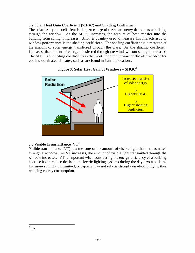
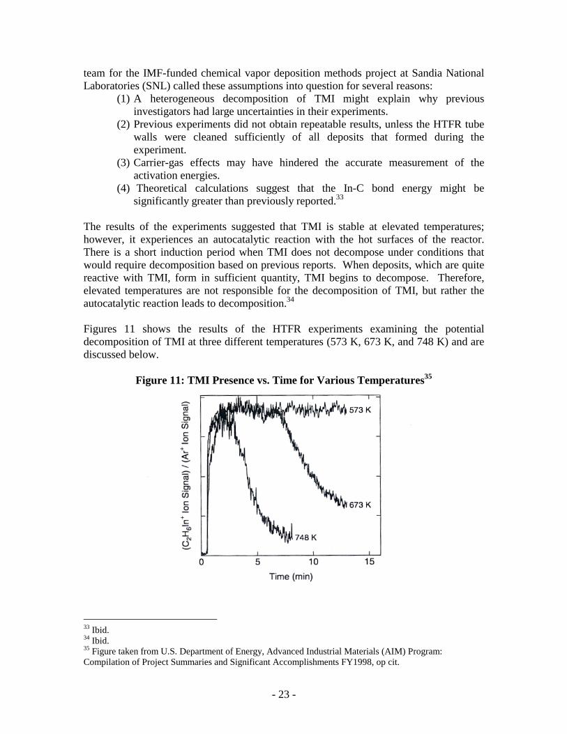