itp industrial distributed energy: assessment of ... · general ... • awareness, information and...
TRANSCRIPT

Assessment of Replicable InnovativeIndustrial Cogeneration Applications
Prepared for:Industrial Center, Inc.
Prepared by:Resource Dynamics CorporationandCSGI, Inc.
Supported by:Oak Ridge National LaboratoryandIndustrial Center Distributed Generation Consortium
June 2001
Resource Dynamics Corporation 8605 Westwood Center Drive
Vienna, VA 22182 (703) 356-1300
www.distributed-generation.com


Assessment of Replicable Innovative Industrial Cogeneration Applications
Table of Contents
List of Tables................................................................................................................................................ivExecutive Summary ......................................................................................................................................1Introduction ...................................................................................................................................................6
Background ...............................................................................................................................................6Objectives..................................................................................................................................................6Approach ...................................................................................................................................................6
Distributed Generation Technologies............................................................................................................8Reciprocating Engines...............................................................................................................................8
History and Status .................................................................................................................................8Operation...............................................................................................................................................8Industrial Cogeneration Potential ..........................................................................................................8
Microturbines ............................................................................................................................................9History and Status .................................................................................................................................9Operation...............................................................................................................................................9Industrial Cogeneration Potential ..........................................................................................................9
Industrial Combustion Turbines..............................................................................................................10History and Status ...............................................................................................................................10Operation.............................................................................................................................................10Industrial Cogeneration Potential ........................................................................................................10
Phosphoric Acid Fuel Cells.....................................................................................................................11History and Status ...............................................................................................................................11Operation.............................................................................................................................................11Industrial Cogeneration Potential ........................................................................................................12
DG Technology Cost and Performance...................................................................................................12Potential Industrial Thermal Applications to Integrate with Cogeneration DG Systems............................14
Hot Water/Direct Contact Water Heaters................................................................................................14General ................................................................................................................................................14Process Uses........................................................................................................................................14Integrating for Cogeneration ...............................................................................................................14Currently Available Systems...............................................................................................................15
Indirect Heating of Thermal Fluids .........................................................................................................15General ................................................................................................................................................15Process Uses........................................................................................................................................15Integrating for Cogeneration ...............................................................................................................16
Direct Heating/Drying.............................................................................................................................17General ................................................................................................................................................17Process Uses........................................................................................................................................18Integrating for Cogeneration ...............................................................................................................19
Indirect Air/Gas Heating .........................................................................................................................20General ................................................................................................................................................20Process Uses........................................................................................................................................20Integrating for Cogeneration ...............................................................................................................20
Refrigeration/Freezing (absorption cooling) ...........................................................................................21General ................................................................................................................................................21Process Uses........................................................................................................................................21Integration for Cogeneration ...............................................................................................................21
Dehumidification.....................................................................................................................................22General ................................................................................................................................................22
i

Assessment of Replicable Innovative Industrial Cogeneration Applications
Process Uses........................................................................................................................................22Integration for Cogeneration ...............................................................................................................22
Use of Exhaust Gas as an Oxidant (including boiler systems)................................................................23General ................................................................................................................................................23Processes Uses.....................................................................................................................................23Integration of Cogeneration Systems .................................................................................................23
General Cogeneration Integration Considerations ..................................................................................24Generic Thermal Process by Industry .....................................................................................................26
Selecting the Top 5 Cogeneration Applications..........................................................................................33Market Assessment Model Input Parameters ..............................................................................................38
Direct Contact Water Heaters .................................................................................................................38Indirect Liquid Heating ...........................................................................................................................39Convection Ovens ...................................................................................................................................40Indirect Air Heating ................................................................................................................................41Exhaust Gas as an Oxidant to Boiler Systems ........................................................................................42
Market Assessment Methodology...............................................................................................................44Market Assessment Results.........................................................................................................................47
Sensitivity Analysis.................................................................................................................................53Conclusions .................................................................................................................................................55
Benefits ...................................................................................................................................................55Barriers ....................................................................................................................................................55
ii

Assessment of Replicable Innovative Industrial Cogeneration Applications
List of Figures
Figure 1. Summary Results by System Type - 11 GW Total Economic Market Potential ..........................2Figure 2. Summary Results by State - 11 GW Total Economic Market Potential .......................................3Figure 3. Summary Results by Size Range ..................................................................................................3Figure 4. Summary Results by Prime Mover Type......................................................................................4Figure 5. Reciprocating Engine....................................................................................................................8Figure 6. Microturbine .................................................................................................................................9Figure 7. Turbine........................................................................................................................................10Figure 8. Fuel Cell......................................................................................................................................11Figure 9. Direct Contact Water Heater System..........................................................................................15Figure 10. Indirect Fluid Heater System ....................................................................................................17Figure 11. Direct Heating/Drying System..................................................................................................19Figure 12. Indirect Air/Gas Heating System..............................................................................................20Figure 13. Refrigeration/Freezing System .................................................................................................21Figure 14. Dehumidification System..........................................................................................................22Figure 15. Exhaust Gas as an Oxidant System for Boiler Systems............................................................24Figure 16. DISPERSE Model.....................................................................................................................45
iii

Assessment of Replicable Innovative Industrial Cogeneration Applications
List of Tables
Table 1. DG Cost and Performance Tables ................................................................................................12Table 2. Thermal Processes by Industry ....................................................................................................26Table 3. Thermal Processes by Industry ....................................................................................................27Table 4. U.S. Annual Energy Consumption for Each Process ...................................................................33Table 5. Direct Contact Water Heater – Input Parameters.........................................................................38Table 6. Indirect Liquid Heating – Input Parameters .................................................................................39Table 7. Convection Oven – Input Parameters...........................................................................................40Table 8. Indirect Air Heating – Input Parameters ......................................................................................41Table 9. Exhaust Gas as an Oxidant to Boiler Systems – Input Parameters ..............................................42Table 10. Financial Parameter Assumptions..............................................................................................45Table 11. Utilities Included in DISPERSE.................................................................................................46Table 12. Summary Results by System Type.............................................................................................47Table 13. Summary Results by State..........................................................................................................47Table 14. Summary Results by Size Range ...............................................................................................47Table 15. Summary Results by Prime Mover Type ...................................................................................47Table 16. Detailed Results by SIC/State (10 Sub-tables)...........................................................................48Table 17. Less Aggressive Installed Cost Reduction - System Type.........................................................53Table 18. Less Aggressive Installed Cost Reduction - State......................................................................53Table 19. Less Aggressive Installed Cost Reduction - Size Range............................................................54Table 20. Less Aggressive Installed Cost Reduction - Prime Mover.........................................................54
iv

Assessment of Replicable Innovative Industrial Cogeneration Applications
Executive Summary U.S. industrial facilities utilize a wide array of thermal process equipment, including:
• Hot water heaters, • Thermal liquid heaters, • Ovens, • Furnaces, • Kilns, • Dryers, • Chillers, and • Boilers.
In most industrial facilities, process heating is provided by direct or indirect heat exchange from fossil fuel-fired combustion systems. Process heating may also be provided by the direct or indirect use of steam supplied by central boiler systems. Many of these systems could be retrofit to become part of integrated distributed generation (DG) cogeneration systems. Cogeneration, or Combined Heat and Power (CHP) systems, generate electricity on-site using turbines, reciprocating engines, or fuel cells and use the “waste” heat from the prime mover to supply some or all of the energy required by thermal processes. Cogeneration systems have high overall efficiencies and, for some facilities, will have lower life cycle costs than conventional solutions.
There has been considerable interest shown in the distributed generation field over the past 5 years. This market movement has gained credence with the distributed generation equipment manufacturers, and they have made substantial investments in the development of new power generation technologies. However, little is being spent to develop innovative industrial cooling and thermal systems and less on how to integrate distributed generation equipment within manufacturing processes, where the greatest opportunity to use waste heat can be found. Adaptation of innovative cogeneration systems is more advantageous from a national energy and environmental policy standpoint than other distributed generation applications because of the high overall efficiency of these systems.
Conventional large cogeneration systems are well developed, widely deployed, and utilize readily available thermal technologies. Their use and benefits are well documented. The thrust of this effort is to look beyond these beneficial and economically-attractive conventional technologies and identify very replicable and innovative cogeneration approaches integrated with selected industrial process operations.
One of the guiding principals of applying cogeneration is the efficient utilization of all energy input to the process. To accomplish this, thermal energy normally rejected needs to be recovered to the maximum extent possible. This can be achieved by recovering heat from the DG equipment exhaust stream, and for engine system, heat can also be recovered from the water jacket, oil cooler, and aftercooler.
This report provides a market assessment of innovative industrial DG cogeneration systems that are less than 1 MWe. The market assessment was developed by:
• Analyzing industrial thermal processes on an industry-by-industry basis and determining annual energy consumption for each industry/process combination,
• Using a methodology to choose five leading thermal processes that can be easily integrated into a cogeneration system and that offer large energy-saving potential,
• Developing integrated DG cogeneration process schematics, and
1

Assessment of Replicable Innovative Industrial Cogeneration Applications
• Assessing the potential market for these systems by comparing their economics with the economics of conventional solutions.
Electricity rates used in this market assessment were based on actual utility electricity rate structures gathered in 1999. Gas rates are based on state average industrial gas rates from 1999, as reported by DOE’s Energy Information Administration (EIA). Escalation rates for electricity and gas are based on 1999 EIA regional projections. Using these values eliminates the gas price spikes of 2000 and uncertain projections regarding electricity rates for the West Coast that surfaced in 2000-2001. If emerging energy price trends and escalation rates are incorporated in a subsequent analysis of the industrial cogeneration opportunities examined in this study, market penetration rates would likely change.1
The five leading cogeneration systems identified are:
• Direct contact water heaters fed directly with engine/turbine exhaust, • Indirect liquid heating using air-to-liquid heat exchangers fed with engine/turbine exhaust, • Convection ovens used for metals fabrication preheating fed directly with engine/turbine exhaust, • Indirect air heating using air-to-air heat exchanges fed with engine/turbine exhaust, and • Central boiler systems using turbine exhaust gas as a combustion oxidant.
The market assessment analysis shows 11 GW of economic market potential for these cogeneration applications. Figure 1 shows the total economic market potential by system type.
Oxidant for Central Boiler System
39%
Indirect Air Heating
Direct Contact WaterHeater23%
Indirect Liquid Heater 9%
Convection Ovens for Metals Fabrication
7%22%
Figure 1. Summary Results by System Type - 11 GW Total Economic Market Potential
Factors that influence economic market potential by system type include:
• Number of facilities in the U.S. with matching thermal processes (there are more facilities with central boiler systems that could be retrofit with cogeneration than potential facilities with convection ovens for metals fabrication),
• Thermal system cogeneration retrofit cost, which affects the total installed cost of the cogeneration system (lower installed cost improves project economics and market potential),
• Existing thermal system efficiency (the lower the existing thermal system efficiency, the more cost-effective the project – indirect air heating efficiency is often below 50%, while convection ovens exceed 85%), and
1 Analysis of the impacts of these recently emerging price trends was outside the scope of this effort.
2

25-775-15
150-40
400-80
800-100
Assessment of Replicable Innovative Industrial Cogeneration Applications
• System sizes for each type (system types where there are more potential facilities with matching thermal processes in the larger size ranges – retrofit, engineering, and installation costs are lower in terms of dollars per kW in the larger sizes).
The 10 states showing the highest economic market potential are shown in Figure 2.
> 1000 MW
500-999 MW
250-499 MW
< 249 MW
Figure 2. Summary Results by State - 11 GW Total Economic Market Potential
Factors that influence market economic market potential by state include:
• Size of the state and industry mix within the state, • Industrial electric rates within the state, and • Industrial natural gas rates within the state.
California has the most applications, because it has the highest number of industrial facilities with matching thermal processes, and also relatively high industrial electricity rates.
Economic market potential broken down by prime mover size range is shown in Figure 3.
6000
MW
Eco
nom
ic M
arke
t Pot
entia
l
5000
4000
3000
2000
1000
0
5Wk
0Wk
0Wk
0Wk
0Wk
Figure 3. Summary Results by Size Range
3

Assessment of Replicable Innovative Industrial Cogeneration Applications
Factors that influence market economic market potential by prime mover size range include:
• Number of potential facilities in each size range (most industrial facilities have electric demands greater than 75 kW), and
• Installation costs (costs are lower as the size ranges increase, because retrofit, engineering, and installation costs are lower in terms of dollars per kW, so this favors the larger size ranges).
Economic market potential broken down by prime mover type is shown in Figure 4.
Recuperated Turbines
8% Reciprocating
Engines 44%
Unrecuperated Turbines
48%
Figure 4. Summary Results by Prime Mover Type
Factors that influence market potential that vary by prime mover type include:
• Prime mover electric efficiency (for most size ranges, reciprocating engines have the highest electric efficiency),
• Available usable thermal output from the prime mover (unrecuperated turbines have the highest), and • Prime mover installed cost (reciprocating engines and unrecuperated turbines are less expensive than
recuperated turbines in all size ranges – for example, the installed costs for a 70-100 kW direct contact water heater system using a recuperated turbine is over $2,400 per kW, but this decreases to under $1,000/kW in the 800-1000 kW size range),
The results shown in this assessment show the economic market potential. There are a number of barriers that may limit applications of these technologies. Some of these barriers may be regional in nature. The barriers include:
• Product performance and availability, • Lack of off-the-shelf integrated systems, • Presence of a supporting market infrastructure, • Awareness, information and education of end users, • Demonstration of successful case studies, • Environmental regulations, • Planning, zoning, and codes, and • Tax treatment.
4

Assessment of Replicable Innovative Industrial Cogeneration Applications
There clearly exists a need for a structured approach to assist with the development and deployment of innovative cogeneration systems in the industrial sector. This approach needs to foster the development of industrial cooling and heating systems that can easily be integrated with distributed generation equipment. The approach should demonstrate these systems in industrial settings and then develop case studies around these demonstrations. These case studies need to include validated and verified data on the systems’ operation and performance. In addition, the structured approach also needs to address the potential barriers and how to overcome them.
Acknowledgement: The report was supported by the Industrial Center Distributed Generation Consortium and the Oak Ridge National Laboratory/U.S. Department of Energy Office of Power Technologies’ Distributed Energy Resources Program, and was developed for the Industrial Center, Inc. by Resource Dynamics Corporation and CSGI, Inc.
5

Assessment of Replicable Innovative Industrial Cogeneration Applications
Introduction
Background The U. S. Department of Energy’s Office of Power Technologies (OPT) and the Industrial Center, Inc. sponsored this work in keeping with their joint goal to significantly improve the resource efficiency and productivity of industries in the United States. In support of this goal, this project will help industries develop technological solutions to critical energy and environmental challenges. Among the solutions being pursued are innovative applications of distributed generation technologies in industrial and institutional cogeneration applications. These technologies have the potential to reduce national energy use and emissions.
A number of trends have surfaced that may lead to growth in industrial cogeneration including:
1. Global concern over greenhouse gas emissions has meant an increased emphasis placed on total energy efficiency, which would favor combined heat and power over utility central plant generation. This outlook may create interest in changing environmental regulations to be less emission based, and more output based, thus favoring the more efficient cogeneration. Furthermore, creation of a global carbon permit trading market would provide new incentives for cogeneration.
2. Electric utility restructuring has heightened concerns over grid reliability and thus is renewing interest in on-site generation. Stranded cost treatment, including exit fees, threatens to counter this interest by deterring non-grid sources of power.
3. New technologies are surfacing, including microturbines and fuel cells. In addition, a new generation of reciprocating engines is entering the market, with higher efficiencies, decreased costs, and lower emissions. In combination, these technologies provide smaller facilities with an unprecedented set of options from which to potentially satisfy their needs for both thermal and electric energy on-site.
Objectives The purpose of this study is to assess the market for innovative and replicable applications of small cogeneration technologies in the U. S. industrial sector. Specific objectives of this study are to:
• Review distributed generation technologies in the 25-1000 kWe size range, • Examine industrial thermal processes that can be integrated with cogeneration systems, • Select the top five innovative and replicable industrial cogeneration technologies in the 25-1000 kWe
size range, and • Assess the potential market for these technologies.
Approach This report is the first task of a larger project that will demonstrate innovative applications of industrial cogeneration systems in actual manufacturing facilities. In order to ensure replicability, this first task will assess the market for cogeneration applications in the 25-1000 kWe size range.
This study identifies five highly replicable innovative cogeneration technologies and assesses their domestic market potential. A five-step approach is used to identify these opportunities and estimate the potential market.
Step 1. Analyze and group industrial thermal processes into seven broad categories, including:
• Hot water, • Indirect liquid heating,
6

Assessment of Replicable Innovative Industrial Cogeneration Applications
• Direct heating and drying, • Indirect air heating, • Refrigeration and freezing, • Dehumidification, and • Furnaces and boilers.
This is done by examining each specific industry within the manufacturing sector (4 digit Standard industrial classifications (SIC) with SICs 20-39), and looking at each of their significant thermal processes.
Step 2. The seven broad categories of thermal processes are broken into more specific categories (e.g., direct heating and drying can be broken into subcategories such as spray drying) and replicability is assessed by estimating the total U.S. annual energy consumption of each specific process. This is done for each industry at the 4-digit level, and the results are aggregated to obtain totals for each subcategory.
Step 3. The top five applications are chosen because of their replicability (energy savings across all applicable SICs) and ease of integration into a cogeneration systems. The five applications selected for the market assessment are:
• Direct contact water heaters, • Indirect liquid heating, • Convection ovens used for metals fabrication preheating, • Indirect air heating, and • Exhaust gas as an oxidant for central boiler systems.
Step 4. Cogeneration system price and performance information is gathered for these five applications.
Step 5. An economic analysis (market assessment) is performed to determine the number of potential applications for these five innovative industrial cogeneration systems. The analysis determines the number of facilities, by 4 digit SIC, size range, and state, where using the cogeneration application is more cost effective than purchasing electricity from the grid and using conventional thermal processes.
7

Assessment of Replicable Innovative Industrial Cogeneration Applications
Distributed Generation TechnologiesA summary of each commercial and near-commercial DG technology is provided below. Included are the technology’s history and current status, operational process, and detailed information on industrial cogeneration potential.
Reciprocating Engines History and Status Reciprocating engines, developed more than 100 years ago, were the first of the fossil fuel-driven DG technologies. oth Otto (spark ignition) and Diesel cycle (compression ignition) engines have gained widespread acceptance in almost every sector of the economy and are in applications ranging from fractional horsepower units powering small hand-held tools to 60 MW baseload electric power plants. Reciprocating engines are machines in which pistons move back and forth in cylinders. ciprocating engines are a subset of internal combustion engines, which also include rotary engines. all to medium sized engines are primarily designed for transportation applications and are converted to power generation units with little modification. Larger engines are, in general, designed for power generation, mechanical drive, or marine propulsion. ciprocating engines are currently available from many manufacturers in all DG size ranges, and can use gasoline, diesel, natural gas, or waste fuels.
Operation Almost all engines used for power generation are four-stroke and operate in four cycles (intake, compression, combustion, and exhaust). The process begins with fuel and air being mixed. e engines are turbocharged or supercharged to increase engine output, meaning that the intake air is compressed by a small compressor in the intake system. he fuel/air mixture is introduced into the combustion cylinder, then compressed as the piston moves toward the top of the cylinder. n diesel units, the air and fuel are introduced separately with fuel injected after the air is compressed by the
Figure 5. iprocating Engine
Air
Natural Gas
Genset
Exhaust
Steam / Hot Water
Cold Water
Lube Oil Heat Exchanger
Jacket Water Heat Exchanger
Exhaust Gas Heat Exchanger
Turbocharger
AC Electricity
Ignition Source Exhaust
Valve
Generator
Piston
Intake Valve
Crankshaft
B
ReSm
Re
Som
TI
Rec
piston in the engine. As the piston nears the top of its movement, a spark is produced that ignites the mixture (in most diesel engines, the mixture is ignited by the compression alone). Dual fuel engines use a small amount of diesel pilot fuel in lieu of a spark to initiate combustion of the primarily natural gas fuel. The pressure of the hot, combusted gases drives the piston down the cylinder. Energy in the moving piston is translated to rotational energy by a crankshaft. As the piston reaches the bottom of its stroke the exhaust valve opens and the exhaust is expelled from the cylinder by the rising piston.
Industrial Cogeneration Potential Reciprocating engines can be used in three different types of industrial cogeneration applications:
• To produce hot water at around 195° F, • To produce low temperature steam at around 265° F, and • To produce heat at higher temperatures, e.g. for drying processes, exhaust gases with temperatures of
930 to 1,000° F can be used directly or by means of a heat exchanger.
8

Assessment of Replicable Innovative Industrial Cogeneration Applications
The following chart shows the electric efficiencies, thermal output, and potential overall efficiency:
Electric Efficiency (% LHV)
Thermal Output (% LHV)
Overall Efficiency (% LHV)
Hot Water 31-38 47-54 80-85 Low Temperature Steam
31-38 18-25 80-85*
High Temperature Heat
31-38 18-34 80-85*
*also includes potential hot water production
Microturbines History and Status The technology used in microturbines is derived from aircraft auxiliary power systems, diesel engine turbochargers, and automotive designs. A number of companies are currently field testing demonstration units for small-scale distributed power generation in the 30-400 kW size range. Several units are available commercially, and more are slated to enter the market in 2001 and 2002.
Operation Microturbines consist of a compressor, combustor,turbine, and generator. The compressors and turbinesare typically radial-flow designs, and resemble Heat to User
automotive engine turbochargers. Most designs are Recuperator Fuel Compressor (most units) (if necessary)
single-shaft and use a high-speed permanent magnetgenerator producing variable voltage, variable frequency Exhaust
alternating current (AC) power. An inverter is Low Temperature
employed to produce 60 Hz AC power. Most Water / Air
microturbine units are currently designed forcontinuous-duty operation and are recuperated to obtain Compressor
higher electric efficiencies. Non-recuperated engineshave lower electric efficiencies, but higher exhaust Airtemperatures, which makes them better for someindustrial cogeneration applications.
Natural Gas
Combuster
Turbine
Figure 6. Microturbine
AC Electricity
Inverter/Rectifier (most units)
Generator
Industrial Cogeneration Potential Microturbines can be used in three different types of industrial cogeneration applications:
• To produce hot water at around 195-205° F, • To produce low temperature steam at around 265° F, and • To produce heat at higher temperatures, e.g. for drying processes, exhaust gases with temperatures of
600 to 1,000° F can be used directly or by means of a heat exchanger.
The following charts shows the electric efficiencies, thermal output, and potential overall efficiency for each type of system:
9

Assessment of Replicable Innovative Industrial Cogeneration Applications
Recuperated Microturbine Electric Efficiency
(% LHV) Thermal Output
(% LHV) Overall Efficiency
(% LHV) Hot Water 25-27 40-55 65-80 Low Temperature Steam
25-27 40-55 65-80
High Temperature Heat
25-27 50-68 75-93
Unrecuperated Microturbine Electric Efficiency
(% LHV) Thermal Output
(% LHV) Overall Efficiency
(% LHV) Hot Water 13-15 52-72 65-85 Low Temperature Steam
13-15 52-72 65-85
High Temperature Heat
13-15 72-80 85-93
Industrial Combustion Turbines History and Status Combustion turbines have been used for power generation for decades and range in size from units starting at about 1 MW to over 100 MW. Units from 1-15 MW are generally referred to as industrial turbines, a term which differentiates them from larger utility grade turbines and smaller microturbines. Combustion turbines have relatively low installation costs, low emissions, high heat recovery, and infrequent maintenance requirements. With these traits, combustion turbines are typically used for large cogeneration systems, as peakers, and in combined cycle configurations. Industrial turbines sized below 1 MW are rare.
Operation Historically, industrial turbines have been developed as aero derivatives using jet propulsion engines as adesign base. Some, however, have been designedspecifically for stationary power generation or for
High Pressure Combustor To Exhaust or Post-
compression applications in the oil and gas industries. A combustion turbine is a device in which air is compressed and a gaseous or liquid fuel is ignited. The combustion products expand directly through the blades in a turbine to drive an electric generator. The compressor and turbine usually have multiple stages and axial blading. This differentiates them from smaller microturbines that have radial blades and are single staged. The intercooler shown in Figure 7 is generally reserved for larger units that can economically incorporate this improvement.
Combustion Emission Controls
Gear Box
Fuel
Power Turbine
Turbine (drives compressor)
Cooling Media
Intercooler
Compressor
Low Pressure Compressor
Air
Figure 7. Turbine
Industrial Cogeneration Potential Industrial turbines can be used in two types of industrial cogeneration applications:
• To produce steam over a range of pressure and temperatures, and
10

Assessment of Replicable Innovative Industrial Cogeneration Applications
• To produce heat at higher temperatures, e.g. for drying processes, exhaust gases with temperatures of 900 to 1,000° F can be used directly or by means of a heat exchanger.
The following chart shows the electric efficiencies, thermal output, and potential overall efficiency for industrial turbines below 1 MW:
Electric Efficiency (% LHV)
Thermal Output (% LHV)
Overall Efficiency (% LHV)
Steam 25-27 45-55 70-80 High Temperature Heat
25-27 59-68 84-93
Phosphoric Acid Fuel Cells History and Status Although the first fuel cell was developed in 1839 by Sir William Grove, the technology was not put to practical use until the 1960’s when NASA installed fuel cells to generate electricity on Gemini and Apollo spacecraft. There are many types of fuel cells currently under development, including phosphoric acid, proton exchange membrane, molten carbonate, solid oxide, alkaline, and direct methanol. However, fuel cells are not generally commercially available, except for a 200 kW phosphoric acid unit made by International Fuel Cells.
Operation There are many types of fuel cells, but each uses the same basic principle to generate power. A fuel cell consists of two electrodes (an anode and a cathode) separated by an electrolyte. Hydrogen fuel is fed into the anode, while oxygen (or air) enters the fuel cell through the cathode. With the aid of a catalyst, the hydrogen atom splits into a proton (H+) and an electron. The proton passes through the electrolyte to the cathode, and the electrons travel through an external circuit connected as a load, creating a DC current. The electrons continue on to the cathode, where they combine with hydrogen and oxygen, producing water and heat.
The main differences between fuel cell types are in their electrolytic material. Each different electrolyte has both benefits and disadvantages based on materials and manufacturing costs, operating temperature, achievable efficiency, power to volume (or weight) ratio, and other operational considerations. The part of a fuel cell that contains the electrodes and electrolytic material is called the “stack,” and is a major component of the cost of the total system. efficiency degrades as stack operating hours accumulate.
Fuel cells require hydrogen for operation. However, it is generally impractical to use hydrogen directly as a fuel source; instead, it is extracted from hydrogen-rich sources such as gasoline, propane, or natural gas using a reformer. Cost effective, efficient fuel reformers that can convert various fuels to hydrogen are necessary to allow fuel cells increased flexibility and commercial feasibility.
Stack replacement is very costly but becomes necessary when Steam Thermal Distribution
Electrolyte
Inverter Electrons
AC Electricity
H2 Fuel
Processor
Fuel
Air/O2
System Anode
Cathode
Exhaust
Figure 8. Fuel Cell
11

Assessment of Replicable Innovative Industrial Cogeneration Applications
Industrial Cogeneration Potential The phosphoric acid fuel cell can be used in two different types of industrial cogeneration applications: • To produce hot water at around 140° F, and • To produce hot water at around 140° F and low temperature steam at 250° F.
The following charts shows the electric efficiencies, thermal output, and potential overall efficiency for the 200 kW phosphoric acid fuel cell:
Electric Efficiency (% LHV)
Thermal Output (% LHV)
Overall Efficiency (% LHV)
Hot Water 37 50 87 Hot Water Plus Low Temperature Steam
37 50 87
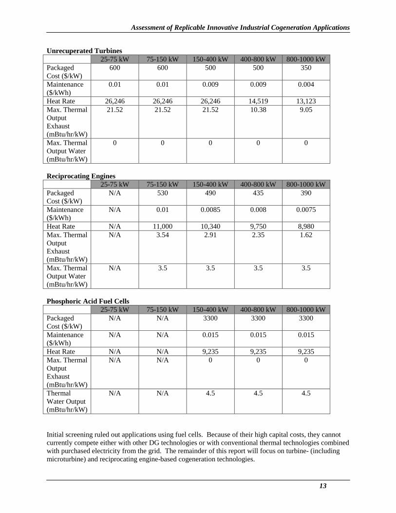
DG Technology Cost and Performance Table 1 shows cost and performance parameters for the each of the generation technologies described. These numbers are used as input data into the model that develops the market assessment presented later in this report. Installation costs and prices for heat recovery equipment depend on the specific thermal application that the generation technology is integrated with, and are presented in later sections of this report.
Table 1. DG Cost and Performance Tables
Recuperated Turbines 25-75 kW 75-150 kW 150-400 kW 400-800 kW 800-1000 kW
Packaged Cost ($/kW)
800 800 700 700 700
Maintenance ($/kWh)
0.01 0.01 0.009 0.009 0.009
Heat Rate 13,200 13,200 13,200 10,434 10,434 Max. Thermal Output Exhaust (mBtu/hr/kW)
8.94 8.94 8.94 6.76 6.76
Max. Thermal Output Water (mBtu/hr/kW)
0 0 0 0 0
12
Assessment of Replicable Innovative Industrial Cogeneration Applications
Unrecuperated Turbines 25-75 kW 75-150 kW 150-400 kW 400-800 kW 800-1000 kW
Packaged Cost ($/kW)
600 600 500 500 350
Maintenance ($/kWh)
0.01 0.01 0.009 0.009 0.004
Heat Rate 26,246 26,246 26,246 14,519 13,123 Max. Thermal Output Exhaust (mBtu/hr/kW)
21.52 21.52 21.52 10.38 9.05
Max. Thermal Output Water (mBtu/hr/kW)
0 0 0 0 0
Reciprocating Engines 25-75 kW 75-150 kW 150-400 kW 400-800 kW 800-1000 kW
Packaged Cost ($/kW)
N/A 530 490 435 390
Maintenance ($/kWh)
N/A 0.01 0.0085 0.008 0.0075
Heat Rate N/A 11,000 10,340 9,750 8,980 Max. Thermal Output Exhaust (mBtu/hr/kW)
N/A 3.54 2.91 2.35 1.62
Max. Thermal Output Water (mBtu/hr/kW)
N/A 3.5 3.5 3.5 3.5
Phosphoric Acid Fuel Cells 25-75 kW 75-150 kW 150-400 kW 400-800 kW 800-1000 kW
Packaged Cost ($/kW)
N/A N/A 3300 3300 3300
Maintenance ($/kWh)
N/A N/A 0.015 0.015 0.015
Heat Rate N/A N/A 9,235 9,235 9,235 Max. Thermal Output Exhaust (mBtu/hr/kW)
N/A N/A 0 0 0
Thermal Water Output (mBtu/hr/kW)
N/A N/A 4.5 4.5 4.5
Initial screening ruled out applications using fuel cells. Because of their high capital costs, they cannot currently compete either with other DG technologies or with conventional thermal technologies combined with purchased electricity from the grid. The remainder of this report will focus on turbine- (including microturbine) and reciprocating engine-based cogeneration technologies.
13

Assessment of Replicable Innovative Industrial Cogeneration Applications
Potential Industrial Thermal Applications to Integrate with Cogeneration DG Systems The section describes the generic industrial applications that can use waste thermal energy.For each generic industrial application, there is a general description, process uses, and details oncogeneration integration. A diagram of the generic process integrated with a microturbine is alsoincluded.
Hot Water/Direct Contact Water Heaters General Process hot water often represents the single largest Btu/hr energy requirement for a manufacturer. Development of highly efficient heat exchange concepts for this purpose has resulted in the ‘direct contact water heating’ scheme. Fundamentally, by raining water down a ‘packed’ column, which also is the stack for combustion products (natural gas), near ideal heat transfer is achieved. Exhaust leaves the system cooled to less than 10oF above the cool water inlet, and the water is able to reclaim well above 90% of the exhaust energy.
Process Uses Abundance, availability, safety and experience make hot water a first choice for manufacturing processes requiring: 1. Washing/flushing
• Equipment “clean-down” and sanitizing in food industries (meat, dairy, sugar refining, etc.), and pharmaceutical and “bio” processes.
• Continuous washing operations in raw food preparation (cane/beet sugars, meat, etc.), textiles, wood/paper pulp, removing oils and other excess matter (paint, dust etc.) in metals fabrication and molded plastics industries (auto parts, sheet metal, cans, food/beverage containers, etc.), and in synthetic rubber and fiber manufacturing.
• Flushing process piping and batch equipment (paint blenders, fermentation vessels, etc.), particularly for operations using the same process lines/equipment to produce slightly varying products (paints, candy slurries, pharmaceuticals, etc.).
2. Solvents for raw material preparation, leaching, separations/extractions, and emission control operations. Water is typically chosen when these systems handle general solid inorganics, acids, generally polar fluids, and crystalline salts.
3. Crystallization/fermentation/reaction media for industries including wine/malt-beverage, dairy, pharmaceutical, and inorganic chemicals.
4. Heating jackets for vessels/operations below ~230oF including chocolate tempering, crystallizers, and storage vessels/mixers containing viscous materials.
Hot water generated from direct contact with natural gas derived combustion exhaust has been approved for food manufacturers including dairy, meat plants, and beverages.
Integrating for Cogeneration To address heat transfer, either more packing media, or extending the height of the column (or both) may be necessary to maintain normal operation (with retrofit systems). Pressure drop and thus back-pressure imposed on the generating system will be a key design element. Special consideration to ensure that no process water enters back into the DG unit’s exhaust system is also crucial for practical implementation.
Many industrial facilities may not have a constant hot water demand. However two profiles may describe the demand well (e.g., normal production operation, and “clean-down” or full capacity day shifts with
14

Assessment of Replicable Innovative Industrial Cogeneration Applications
part capacity night shifts). In the latter case, a bypass-recuperator option on a turbine-based cogeneration scheme can be integrated with a variable flow water tower to switch between profiles. Assuming precise hot-water energy requirements are known, a recuperator with bypass can be designed to maintain total system efficiency by diverting some or all of the exhaust past the (turbine) recuperator to boost the hot water delivery to the desired level.
Currently Available Systems There are currently two off-the-shelf small industrial cogeneration systems available in the marketplace to generate hot water. The first system is a microturbine-based solution that works like the indirect liquid heating system described later in this report. An air-to-water heat exchanger is used with the turbine exhaust gases to heat water.
The second system is a standard reciprocating engine cogeneration system. These systems use liquid-to-water heat exchangers on the water jacket cooling fluid, the lubricating oil system, and sometimes on the aftercoolers. Some of these systems also use an air-to-water heat exchanges on the engine exhaust.
Exhaust
Cold Water
Hot Water
Exhaust
Recuperator
Generator
Compressor Turbine
Intake Burner
Air
Fuel
Figure 9. Direct Contact Water Heater System
Indirect Heating of Thermal Fluids General Many operations, requiring energy delivery to a liquid-phase (and/or fluid) stream, require a physical barrier between the fossil burn (energy release) and the process stream. The barrier reduces heat transfer efficiency, but is often necessary. Traditional systems depend upon heat delivery via heat exchangers, fire-tube schemes (heating coils, or multi-pass fluid heaters) and other methods. Many of these systems use flame induced, radiant based heating to rapidly deliver well over 50% of the required energy.
Process Uses Situations involving high (and/or variable) pressure systems, separation/purification operations, multi-phase operations, systems impeded by oxidation (or other possibly reactive/degrading components of
15

Assessment of Replicable Innovative Industrial Cogeneration Applications
combustion), and/or strictly maintained closed-loop systems are common boundaries to direct heating of process streams. More specific operations and their manufacturing environments include:
1. Purification, recovery, and separations. • Chemicals/refinery distillation (reboilers, etc.), and flash evaporators (polymer processing, slurry
separations/purification, brine treatment, etc.). 2. Pressurized process streams (chemical reactors, etc.). 3. Processes/products sensitive to oxidation, other reaction-driven degradation, and/or general fouling
(chemical, food, pharmaceutical processing, etc.). 4. Vat or batch systems maintaining a heated fluid (paint/dye blenders, food deep fryers, refinery-
bottoms storage and subsequent processing, reactor/fermentation vessels, crystallizers, etc.). 5. Thermal fluid, closed-loop-heating systems for processes, often including those already mentioned,
requiring especially high and smoothly controlled temperature profiles. • Systems requiring high temperatures over large areas such as calcium chloride crystallizers. • Pipe line tracing.
− Distillation and reactor feed lines whereby preheating feed components simplifies the energy delivery and/or chemistry complexity of that downstream operation.
− Heat tracing viscous material (crude, confectionery, polymer melts, etc.) pipelines to reduce electric driven pumping.
• Tool heating (including plastics/rubber extruders, molds), paper mill platens and rollers, metal fabrication equipment, laminate setting, and others.
• General polymer processing. Polymer processing plants may require high temperature (> 400oF) energy delivery to several unit operations because of high “pure” polymer melting points (maintained for extrusion, molding, etc.), and endothermic and/or equilibrium limited reactions (whereby light byproducts, often water, must be continuously evaporated and removed for effective/efficient reactor output). Polyester and Nylon 6,6 are good examples of major international commodities often utilizing thermal fluids systems throughout their production cycle.
Integrating for Cogeneration The wide variety of thermal “fluid” heating applications mentioned above reflects the broad scope in unit operations, engineering techniques, and process chemistries involved in this concept category. For this section, three general interconnection (with cogeneration) systems will be discussed. 1. Systems not relying on radiant energy delivery.
Systems currently delivering heat to a process fluid via combustion exhaust energy only (or other forced convection media), either through a series of tubes, vessel/pipe jacket, or compact heat exchanger (shell and tube, plate unit, etc.) can be easily adapted to receive cogeneration based thermal energy. Because the majority of a DG unit’s thermal output is in the form of hot exhaust, the key concerns would be matching the temperature, gas volume, and pressure parameters to those experienced prior to cogeneration integration. This may require little or no rebuilding of the process heat exchange equipment, but needs to consider the operating tolerance of the DG unit.
2. Systems relying on radiant (flame induced) energy transfer. Unless there is little radiant energy transfer contribution (relative to the entire quantity delivered by the process operation) and/or the flame temperatures are low (< 1500oF), even an unrecuperated turbine cannot match the heat transfer characteristics expected in the existing process heat transfer unit. Several combinations may then compete on a cost benefit and space based analysis. Many systems delivering a majority of the energy via high temperature, flame induced radiation leave a significant amount of the unit volume for flame (radiant rays) “space” only. If this space were utilized to generate more passes (fluid tubing), thereby increasing heat
16
Assessment of Replicable Innovative Industrial Cogeneration Applications
transfer area, the operation could be more readily fit by a cogeneration scheme. It may be the case that the original heat transfer unit cannot be properly modified. However, if the feed line to the heater unit is relatively low temperature (70-300oF), a heat exchanger extracting cogeneration energy prior to entering the main heater could result in a sizable turn down of fuel delivery to that unit. Another option would be the use of duct burners to increase the fuel gas temperature to the required levels.
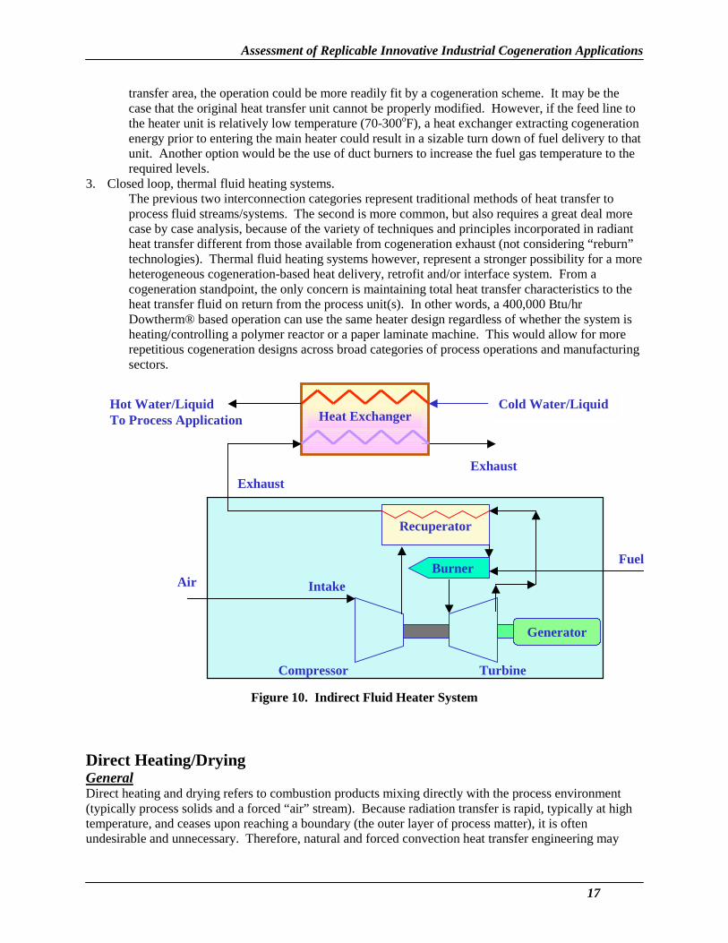
3. Closed loop, thermal fluid heating systems. The previous two interconnection categories represent traditional methods of heat transfer to process fluid streams/systems. The second is more common, but also requires a great deal more case by case analysis, because of the variety of techniques and principles incorporated in radiant heat transfer different from those available from cogeneration exhaust (not considering “reburn” technologies). Thermal fluid heating systems however, represent a stronger possibility for a more heterogeneous cogeneration-based heat delivery, retrofit and/or interface system. From a cogeneration standpoint, the only concern is maintaining total heat transfer characteristics to the heat transfer fluid on return from the process unit(s). In other words, a 400,000 Btu/hr Dowtherm® based operation can use the same heater design regardless of whether the system is heating/controlling a polymer reactor or a paper laminate machine. This would allow for more repetitious cogeneration designs across broad categories of process operations and manufacturing sectors.
Cold Water/LiquidHot Water/Liquid To Process Application
Exhaust
Heat Exchanger
Recuperator
Generator
Compressor Turbine
Intake Burner
Air
Fuel
Exhaust
Figure 10. Indirect Fluid Heater System
Direct Heating/Drying General Direct heating and drying refers to combustion products mixing directly with the process environment (typically process solids and a forced “air” stream). Because radiation transfer is rapid, typically at high temperature, and ceases upon reaching a boundary (the outer layer of process matter), it is often undesirable and unnecessary. Therefore, natural and forced convection heat transfer engineering may
17

Assessment of Replicable Innovative Industrial Cogeneration Applications
dominate dryer design. There are a wide variety of process dryers, kilns, calciners, ovens, etc. that incorporate an even greater range of combinations in forced convection, radiation, and conduction (through the material) heat transfer principles to satisfy the product requirements. In all cases, however, the heat energy supplied to a system must perform the following four tasks: 1. Heat the dryer feed to the “light” component’s vaporization temperature. 2. Vaporize and/or free the liquid/byproducts above the solids’ surface. 3. Heat the solids to the final desired temperature, and for the desired duration of time. 4. Heat the vapor to the final desired temperature.
Process Uses Numerous factors, including production throughput, local steam, natural gas and electricity prices, emissions restrictions, and equipment cost considerations, often result in similar solids being dried in very different ways. However, common direct drying/heating operations and their typical product/process applications include: 1. Bringing variable water-weight percent feeds to a desired initial processing concentration.
• Mined raw materials and/or prepared mixes fed to cement, gypsum, ceramics, and lime processes require crushing, sizing, and drying. Rotary dryers, impact dryers, drum dryers, and others are used to handle large volume, variable composition slurries. Water removal to organize/homogenize process streams for inorganic chemicals manufacture is also common.
2. More complete drying of slurries containing finer solids within certain size/weight specifications is carried out using spray dryers, thin-film dryers, and drum dryers. • Within the Stone, Clay, Glass and Cement manufacturing sector (SIC 32), fine dry powders are
desirable for handling, packing, and/or to produce a more consistent product. Specific products include kaolin clay, fluid cracking catalysts and ceramics that may also use this step to introduce property enriching additives/binders to the material.
• Emulsion PVC and PVP polymer processes often employ spray drying to rapidly remove water without degrading product.
• Milk/dairy powders. • Organic and inorganic dry soaps, detergents, dyes and pigments.
3. Pre-heating/drying materials. • Metals fabrication and/or scrap metal industries use direct heat to remove volatile impurities (oils,
plastics, paints, etc.) and/or to reduce energy demand of central furnace operations. • Large kilns, calciners, and ovens (primarily in SIC 32) also benefit from preheated feeds, often
containing preheat sections as part of the primary unit (tunnel kilns, etc.). • Coke processes may preheat coal feeds to reduce moisture content. • Glass and mineral wool industries utilize many preheat techniques to reduce energy demands or
increase throughput on central furnaces systems. 4. Drying and heating meant to relieve chemically bound light components and/or otherwise modify
solid structure. Rotary kilns, shaft kilns, kettle calciners, flash calciners, brick ovens/houses, tunnel kilns, regenerative kilns, and others are included in this grouping. • Kilns and ovens used for bricks, ceramics, etc. where residence times in hot and dry conditions
may last hours to days to obtain desired final qualities in appearance and structure. • Kilns and calciners used to produce/process gypsum, plasters, cements, limestone, etc. where
energy not only thoroughly removes any remaining water, but also frees intimate impurities, and forces various reactions often resulting in the release of carbon and sulfur oxides. Along with those operations in SIC 32, both the pulp & paper and beet sugar industries use these lime kiln technologies.
5. Drying to remove water (and/or other solvents/chemicals) added, left, or produced during processing. • Starch, stalk and husk dryers, and fruit peel and feed dryers, used in beet and cane sugar
manufacturing, grain mill products, and other SIC 20 manufacturing sectors.
18

Assessment of Replicable Innovative Industrial Cogeneration Applications
• Convection dryers in textile manufacturing. • Veneer and other lumber/wood-furniture dryers. • Pulp dryers, coated and tissue paper dryers in SIC 26. • Dryers including conveyor and tray dryers used in non & cellulosic fibers (rayon, acrylics, etc.)
processing, polymer rubbers manufacture, for pharmaceuticals, and latex. 6. Granulators, fluidized bed systems, rotary dryers, and tower dryers often used for producing finished
grains, sugar, and fertilizer.
Integrating for CogenerationMany kilns and calciners depend on high temperature (1000-2000oF) exhaust and radiant heating sectionsthat could not be supplied by cogeneration exhaust alone. However, preheating operations can takeadvantage of cogeneration. Although many “direct” preheating systems recover stack gas from onsitefurnaces and central calciners/dryers, the gas often requires filtering or other treatment to removeparticles, sulfurous gases, and other components that can otherwise deteriorate equipment and causehealth concerns. Sites with successful existing preheating not derived from cogeneration may seeadditional turndown (on the primary unit’s fuel feed) without high retrofit costs if the system can handlean extra volume of exhaust (from a cogeneration scheme) and assuming temperature conditions aresimilar to the existing preheater’s hot gas feed. Drying operations at facilities without processingfurnaces, (e.g., calciners) could completely supplement a non-radiant based dryer. However, some directdryers burn cheap fuels (e.g. wood, pulp waste, coal) and so emissions considerations may drive the finaldecision.In all cases, drying systems can contain a complex array of blowers and fans to promote improved heattransfer and efficiency. Back pressures on the DG unit may require controls and monitoring at each dryerentry point (of hot gases into the system) depending on the design.
Note: Typical unit operations literature may define direct drying to include solids receiving energy from any heated gas (combustion products/air mixtures, and hot air only are two of the most common media). This report distinguishes between the two, not because the process solid experiences different heat transfer profiles (it, essentially, does not), but because the integration of the cogeneration equipment is different.
Exhaust Oven / Kiln
Aux. Burners
Air
Fuel
Recuperator
Generator
Compressor Turbine
Intake Burner
Air
Fuel
Exhaust
Figure 11. Direct Heating/Drying System
19

Assessment of Replicable Innovative Industrial Cogeneration Applications
Indirect Air/Gas Heating General Air heaters or inert gas heaters are commonly considered when products, process operations, or the facility environment are potentially compromised by using direct drying/heating systems. Because issues including plant layout, local regulations, and fuel type affect these considerations, many of the processes in this section and the preceding section are served by both indirect and direct heating.
Process Uses Two general processing categories are considered: 1. Food products cooking, baking, and drying.
• Roasters used in coffee and cocoa processing. • Baking ovens used for breads, cakes, etc. • Toasting and drying systems for cereals.
2. Finish drying and curing systems. • Dryers following painting and or final cleaning operations in furniture and metals fabrication
industries (transportation & industrial equipment, beverage cans, etc.). • Dryers used in finishing periodicals and newspaper production processes.
Integrating for Cogeneration Air heaters are often industrial versions of fired furnaces used in HVAC systems. Although many of the operations mentioned above require only modest heat (200-600oF), the heater itself may have radiation-induced “hot side” temperatures above 1500oF. A new type of heat exchanger may be needed for some applications.
Cold Air/Gases To Process Application
Exhaust Exhaust
Heat Exchanger
Recuperator
Generator
Compressor Turbine
Intake Burner
Air
Fuel
Hot Air/Gases
Figure 12. Indirect Air/Gas Heating System
20

Assessment of Replicable Innovative Industrial Cogeneration Applications
Refrigeration/Freezing (absorption cooling) General Refrigeration/freezing refers to a direct process end use in which energy is used to lower the temperature of substances involved in the manufacturing process. Conventional equipment includes industrial chillers and absorption cooling equipment.
Process Uses Major applications of industrial cooling include: • Refrigerated storage of unfrozen foods, • Frozen foods, • Refrigeration to change the chemical structure of food, • Freeze drying, • Industrial process air conditioning, and • Refrigeration in the petroleum and chemicals industries (reaction heat removal, gas separations,
condensation of gases, separations, solidifications, humidity control, etc.).
Integration for Cogeneration Absorption cooling systems require a source of heat. For an ammonia-water cooling system, the heat is required to separate the water and ammonia. In conventional absorption systems, this heat is supplied by steam heat exchangers, an electrical heater or a gas fired heater. For cogeneration systems, this heat can be supplied by using a heat exchanger where clean exhaust gases from a turbine or other type of prime mover is used as a heat source. The heating gases may have to be mixed with air or other gases to maintain desired heating gas temperature. Such a system will reduce or eliminate heat input for the overall system.
Heating Gases
Recuperator
Generator
Compressor Turbine
Intake Burner
Air
Fuel
Exhaust
Figure 13. Refrigeration/Freezing System
21

Assessment of Replicable Innovative Industrial Cogeneration Applications
Dehumidification General Desiccant-based dehumidification systems are used extensively for removing moisture from moist air or gases in many industrial applications. Some typical industries where such systems are used include chemical, pharmaceutical, food, semi-conductor manufacturing, and vacuum processing. These systems are also used for climate control applications in commercial buildings. Operation of these systems includes a regeneration step where hot air (or other gases) are used to remove moisture from saturated desiccant media.
Process Uses Major applications of dehumidification in the manufacturing sector include: • Pharmaceutical processing, • Candy coating, • Storage and packing, • Conveying of hygroscopic powders, • Composite manufacturing, • Semiconductor manufacturing, • Printing operations, • Corrosion prevention, • Molding operations, and • Drying operations.
Integration for Cogeneration In the cogeneration system, clean exhaust gases will be mixed with ambient air to raise the temperature to the desired value. Currently, a variety of heating methods and media are used for supplying hot regenerative air. The heating methods include heating by electricity, steam, or a fuel (usually gas) fired burner. Application of such a scheme may require redesign of the regenerative air system for a retrofit application. For a newer application, such changes can be accounted for during the design phase of the project.
Cooling
Heater
Recuperator
Generator
Compressor Turbine
Intake Burner
Air
Fuel
Exhaust
Figure 14. Dehumidification System
22

Assessment of Replicable Innovative Industrial Cogeneration Applications
Use of Exhaust Gas as an Oxidant (including boiler systems) General Combustion reactions are highly exothermic. However, their reactants (fuel and oxidant) continuously absorb considerable energy to reach proper combustion temperatures. Exhaust gases from a prime mover, particularly from a gas turbine (because of its high oxygen content), provide an excellent preheated oxidant. These gases can be considered as an oxidant source for combustion of fossil fuels used in most heating applications including steam generators or boilers.
Processes Uses Applications for using exhaust gases as an oxidant include: • Central boiler systems, • Waste VOC incineration systems, • Kilns, • Calciners, • Large ovens, • Large heat treating operations, • Large furnaces, • Forging operations, • Tempering operations, • Annealing operations, and • Cupolas.
Integration of Cogeneration Systems Many engineering techniques addressing the principle of preheating the combustion reactant feed (especially the oxidant, because its volume generally dominates the reactant mixture) are in practice. Three categories represent a majority of these techniques: 1. Using the stack exhaust to indirectly (e.g., with a shell and tube exchanger) heat the air/oxidant feed
line. 2. Burner tip techniques that often incorporate ceramics to maintain the final mixing chamber at
extremely high temperature, thereby heating the reactants immediately prior to ignition. 3. Using high temperature, high oxygen content, waste-heat streams as a combustion reactant/oxidant
(as the DG cogeneration system would offer).
In general the cogeneration based oxidant system is highly competitive for these options when: 1. The process operation is operated such that its own exhaust is either low in temperature or low in
excess oxygen. 2. The process operation uses coal (or other fuels releasing soot and sulfur in the exhaust) as a fuel. In
such cases cogeneration offers both a relatively clean preheated feed (so as not to foul the burner equipment) and also reduces the amount of sulfur and particulate released (by reducing the amount of coal needed).
If a system’s burner was initially designed for low temperature air feeds, more heat durable components may be needed to handle a hot oxidant. The difference in oxygen content also needs careful consideration to properly engineer the combustion system.
23

Assessment of Replicable Innovative Industrial Cogeneration Applications
BurnerBoiler
Fuel
Exhaust
Heat Recovery System
Feed Water
“Air”
Preheater
Steam
Recuperator
Generator
Compressor Turbine
Intake Burner
Air
Fuel
Exhaust
Figure 15. Exhaust Gas as an Oxidant System for Boiler Systems
General Cogeneration Integration Considerations Integration into a specific manufacturing facility will always require further site-specific analyses. However, there are several general considerations pertinent to determining how a specific existing operation is altered (from an engineering perspective) when driven or partially supported through cogeneration.
1. Heat transfer rates to the process media are often reduced when using exhaust (the typical heat media from a cogeneration unit) as opposed to a burner-based operation (e.g., a process furnace). Though the quantity of heat energy available from a DG unit is often sufficient to maintain a process operation from an energy balance standpoint, the dynamics (temperature and energy transfer profiles) can be significantly different. This is because high temperature (1500-4000oF), luminous flames induce radiant based heating (rays of energy moving at the speed of light), whereas cogenerated exhaust energy ranges from 450-1100oF and moves via convection-conduction only. A common remedy is an increase in the heat transfer area (and therefore the equipment size).
2. Batch systems and other operations with non-constant temperature/energy requirements, including fermentation, reactor, and mixing vessels, are often dependent upon dynamic heating systems to accommodate “cold” start-ups, and varying endo/exo-therms and temperature profiles. These systems are not always ideal for cogeneration schemes.
3. Auxiliary burners, or maintaining the existing burner system (depending on its flexibility), can increase the flexibility and therefore applications of cogeneration systems. The primary driver for investing in a distributed generation (leading to a cogeneration option) unit is the electricity output. Constant electrical delivery typically results in constant heat delivery (although variations in heat recuperation, fuel feed, etc. can allow for some flexibility). However, for a process such as the batch systems addressed above, there may be a row of three burners heating the vessel. If a “batch” cycle
24

Assessment of Replicable Innovative Industrial Cogeneration Applications
ran one hour, needing all three burners for the first 20 minutes, and one or two thereafter, a steady cogenerated heat stream could replace the “one or two” burners needed constantly, while the third would remain to maintain the initial per-batch heat requirement.
4. Controls systems monitoring and maintaining operations incorporating a cogeneration scheme may need to be modified or completely re-engineered. Automated control systems on a typical burner based system will monitor one or more parameters of the process and then adjust fuel/oxidant feeds to the burner accordingly. If a system is heated via exhaust from a cogeneration scheme, the control system might include a by-pass system (e.g., a recuperator) or on/off auxiliary burner concepts.
25

Assessment of Replicable Innovative Industrial Cogeneration Applications
Generic Thermal Process by Industry Table 2 shows the applicability of each generic thermal process to each manufacturing sector.
Table 2. Thermal Processes by Industry
Industry
Direct Contact Water Heater
Indirect Liquid
Heating
Direct Heating
Drying
Indirect Air/Gas Heating
Refrig Freeze
Dehumid ification
Exhaust Gas
Oxidant (non-
boiler)
Exhaust Gas
Oxidant (boiler)
20 – Food X X X X X X X X 21 – Tobacco X X X 22 – Textiles X X X X 23 – Apparel X X 24 – Wood X X X 25 – Furniture X X 26 – Paper X X X X X 27 – Printing X X X X X 28 – Chemical X X X X X X X X 29 – Petroleum X X X X X X 30 - Rubber Plastics X X X X X X 31 – Leather X X 32 - Stone Clay Glass X X X X X 33 - Prim Metals X X X X X X X 34 - Fab Metals X X X X X 35 – Machinery X X X X 36 – Electronics X 37 – Transport X 38 – Measuring Equipment X X 39 - Misc. X
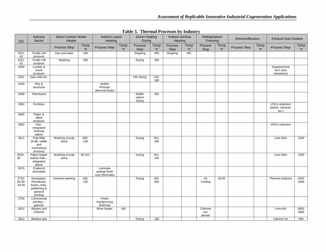
Table 3 shows significant thermal processes by 4-digit SIC, describes each process step in more detail, and gives an indication of temperature ranges for each process.
26

Assessment of Replicable Innovative Industrial Cogeneration Applications
Table 3. ermal Processes by Industry
SICIndustrySector
Direct Contact WaterHeater
Indirect LiquidHeating
Direct HeatingDrying
Indirect Air/GasHeating
Refrigeration/Freezing Dehumidification Exhaust Gas Oxidant
Process Step Temp°F Process Step Temp
°FProcess
StepTemp
°FProcess
StepTemp
°FProcess
StepTemp
°F Process Step Temp°F Process Step Temp
°F2026 Fluid Milk Washing 90 Pasteurizing 165 Cooling 332026 Fluid Milk Milk refrig. 402026 Dried/evap
milkSpraydrying
350-500
Milkproductstorage
38
2033 Preservedfruits & vegs.
Washing Watercooling
45-60
2040 Grain millproducts
Process(Steeping) Hot
Water
125 -140
Process(Steeping) Hot
Water
125 -140
Drying/Roasting for
starch,germ
160 -250
Drying/Roastingfor starch,
germ.
160 -250
2040 Grain millproducts
Clean-up/Washing hot
water
140 Drying forfeed andproduct
300 -450
Drying forfeed andproduct
300 –450
2050 Bakeryproducts
Bakingovens
400 –600
2060 Sugar &confection.products
Process HotWater (Mingler,
melter etc.)
165 to195
Process Hotwater (Mingler,
melter etc.)
165 -195
Spaceconditioning
(humiditycontrol)
75
2060 Sugar &confection.products
Drying -granularproduct
165 -250
Drying forgranularproduct
165 -250
2060 Viscousmaterials
(molasses,etc.)
Hot oil (thermalfluids), storage
& pumping
2062 Cane sugarrefining
Washing 140 Charcoalregenerator
900 Charcoalregenerator
900
2063 Beet sugarproduction
Process Hotwater (Mingler,
melter etc.)
165 -195
Kiln dryer 200 Lime kiln 600
2066 Chocolate Cocoaroaster
500 -600
2070 Fats & Oils VOCs reduction2080 Malt
BeveragesProcess Hot
Water(pasteurization,
filtering, etc.)
165 Process HotWater
(pasteurizationfiltering, etc.)
165 Grain dryers 600-700
Cooling,ferment-ation etc.
20 -60
2087 Extracts &syrups
VOCs reduction
2090 Coffee Roaster 9002000 Chips, french
fries, fish,doughnuts,
etc.
Oil fryers(thermal fluids)
400-600
2100 TobaccoProducts
Washing 120-140
Kiln dryer 180-220
Storage 40
Dry andframe
180
Th
Assessment of Replicable Innovative Industrial Cogeneration Applications
Table 3. ermal Processes by Industry
SICIndustrySector
Direct Contact WaterHeater
Indirect LiquidHeating
Direct HeatingDrying
Indirect Air/GasHeating
Refrigeration/Freezing Dehumidification Exhaust Gas Oxidant
Process Step Temp°F Process Step Temp
°FProcess
StepTemp
°FProcess
StepTemp
°FProcess
StepTemp
°F Process Step Temp°F Process Step Temp
°F2221-
62Textile millproducts
Dye and wash 140 Singeing 400 Singeing 401
2221-62
Textile millproducts
Washing 180 Drying 250
2400 Lumber &wood
products
Supplementalburn (low
emissions)2421 Saw mills etc. Kiln drying 120-
1802430 Plys &
structuralMolds/
Presses(thermal fluids)
2499 Fiberboard Stabili-zation/drying
350
2500 Furniture VOCs reduction(paints, solvents,
etc.)2600 Paper &
alliedproducts
2600 Non-integratedfinishingplants
VOCs reduction
2611 Pulp Mills(Kraft, sulfite
andmechanical
process)
Washing of pulpstock
900-100
Drying 151-240
Lime kilns 1200
2620-30
Paper (paperboard) mills –
integratedplants
Washing of pulpstock
90-101 Drying 151-240
Lime kilns 1200
2670 Coated &laminated
Laminatesetting/ finish
cure (thermals)2710-20-30-40-50
Newspaper,Periodicals,books, misc.publishing &
generalprinting
General washing 100-120
Drying 150-200
AirCooling
40-60 Thermal oxidizers 1400-1600
2750 Commercialprinting –gravure
Finishdrying/curing
(thermal)2812 Alkalies and
ChlorineBrine heater 160 Chlorine
con-denser
Lime kiln 1600-1800
2812 Alkalies and Drying 180 Calciner for 650
Th

Assessment of Replicable Innovative Industrial Cogeneration Applications
Table 3. ermal Processes by Industry
SICIndustrySector
Direct Contact WaterHeater
Indirect LiquidHeating
Direct HeatingDrying
Indirect Air/GasHeating
Refrigeration/Freezing Dehumidification Exhaust Gas Oxidant
Process Step Temp°F Process Step Temp
°FProcess
StepTemp
°FProcess
StepTemp
°FProcess
StepTemp
°F Process Step Temp°F Process Step Temp
°FChlorine NAHCO3
Anhydrouscaustic soda
Evaporators(thermal)
700
2813 H2generation –
steamreformer
Amminesolution
reactivator
220 Reformer heating 1500-1600
2813 H2generation –
steamreformer
CO converter 800
2816 Inorganicpigments
Washing 120-140
Pigment(spray)dryer
325 -1200
Chilledwater
40 Ti 02 Heater &Vaporizer
1120
2816 Inorganicpigments
02 Heater 1120
2819 Inorganicchemicals
Ore leaching 180 Drying 250-350
Calciner – Ti02 1500
Sodiumtripolyphos-
phate
Spray dryer
2821 Plastic resins Hot oil forheating
400-450
Drying 250-350
2821 PVP & PVCemulsion
Spraydryers
300-400
2821 LDPE,polystyrene
Variousequipment
(thermal fluids)
600-800
2821 PTA Preheathydrogener-ation feed(thermals)
700 CTA & vent gas(VOCs)
incineration
2822 SyntheticRubber
Storageheating
200-250
Emulsionreactor
40
2822 SyntheticRubber
Drying 180 Chilledwater forextruders
mixers etc.
40
2822 SyntheticRubber
Preheaters(Ethylene)
120 Pre-heaters(Ethylene)
120
2823 Manmadefibers
Hot water forwashing – fibers
180-200
Drying 120-200
2823 Manmadefibers
Pulp preheating 90-100 Pulppreheating
90-100
2824 Organicfibers
Drying 120 Reactor heating 450-500
2824 Polyester,nylon 6-6
Melters, evaps,etc. (thermals)
400-1000
Melter 320 Polymer melter 450
2824 Polyester,nylon 6-6
Drying 150 Polymerizer 540
Th

Assessment of Replicable Innovative Industrial Cogeneration Applications
Table 3. ermal Processes by Industry
SICIndustrySector
Direct Contact WaterHeater
Indirect LiquidHeating
Direct HeatingDrying
Indirect Air/GasHeating
Refrigeration/Freezing Dehumidification Exhaust Gas Oxidant
Process Step Temp°F Process Step Temp
°FProcess
StepTemp
°FProcess
StepTemp
°FProcess
StepTemp
°F Process Step Temp°F Process Step Temp
°F2824 Pharma-
ceuticalsContainerwashing
80-100 Drying 200-250
Drying 200-250
Productioncell atmos-pherecondition-ing
50-70 Production cellatmosphereconditioning
75
2824 Pharma-ceuticals
Purification/recovery of
heat-sensitiveproducts(thermal)
2841 Soaps &detergents
Spraydryers
2850 Paints etc. Storage &Pumping
(thermal fluids)2865 Cyclic crudes
andintermedi-
ates
Pre-heaters 400-500
Reactor –chiller
-20 Steam heaters/super heaters
750-1300
2865 Dyes &pigments
Spraydryers
350-700
Reformer(methanol)
1500
2865 Styrene Separations,recovery, etc.
(thermals)
500 Shift reactor 550-600
2865 p-xylene Isomerization& separations
(thermals)
1000
2869 Capro-lactam,acryloni
2869 VCM Purificationrecovery
HCI cond. -22
2869 VCM EDC cracker 1000 Coolingwater
2869 Acetic acid Purificationrecovery
300
2873 Fertilizer Drying 150-200
MethanePreheat-
ing
400-500
Reactor –Chiller
-20 Reformer(methane)
1500
2911 Petroleumrefining
2911 Petroleumrefining
Preheating ofcrude
Preheating 450-500
Preheating 450-500
2911 Distillation Heating 750-780
2911 Coking Heating 900-1100
2911 Vis breaking Heating 70-1000
2911 Lube oil Heating 200-
Th

Assessment of Replicable Innovative Industrial Cogeneration Applications
Table 3. ermal Processes by Industry
SICIndustrySector
Direct Contact WaterHeater
Indirect LiquidHeating
Direct HeatingDrying
Indirect Air/GasHeating
Refrigeration/Freezing Dehumidification Exhaust Gas Oxidant
Process Step Temp°F Process Step Temp
°FProcess
StepTemp
°FProcess
StepTemp
°FProcess
StepTemp
°F Process Step Temp°F Process Step Temp
°Fprocessing 450
2911 Reforming Heating 1100-1400
2911 Alkylation Vaporcondens.
-10 –40
Dehumid of feed Ambient
2911 Recoveryboiler
CO burning 1000-1600
2950 Asphalt Heating 250-350
Dryingprocess
250-400
VOC reduction
2990 Misc.petroleum
Heating 250-350
VOC reduction
3069 Fabricatedrubber
Thermal fluids 350-600
Drying 120-150
Chilledwater
40
3069 Plasticsproducts
Thermal fluids 350-600
Lamin.,cast, mold
250-350
Chilledwater
40
3069 Tire recycling Melting32213222
Glass Culletdrying
preheating
250-1000
Annealing 900-1000
32213222
Glass Tempering 1300-1600
32213222
Glass Laminatingheating
1000-1100
3229 Fiber glass Curingovens
350-650
Curing ovens 350-650
3240 Cement Hot water 120-140
Dryers, clinkers
32503260
Clay products Hot water 120-140
Spraydryers
300-1100
3270 Concrete,gypsum,plaster
Hot water 120-140
Lime kilns
3296 Mineral wool Curing Curingovens
350-650
Curing ovens 350-650
3296 Mineral wool Cupolas3310 Coke from
coalPre-drying
coal33103312
Blastfurnacessteel mills
Pickling 160 Pickling 160 Scrapdrying
preheating
350-600
Blastfurnacestove airpreheat
200-800
Blast furnacedehumid.
75-90 Scrap preheat 1000-1200
33103312
Blastfurnacessteel mills
Loadpreheating
250-600
Direct firedfurnaces
600-2500
33103312
Blastfurnacessteel mills
Ladle drying 300-400
3313 Electromet.Products
Ore drying 300-400
Preheating kilns 1200-1600
Th

Assessment of Replicable Innovative Industrial Cogeneration Applications
Table 3. ermal Processes by Industry
SICIndustrySector
Direct Contact WaterHeater
Indirect LiquidHeating
Direct HeatingDrying
Indirect Air/GasHeating
Refrigeration/Freezing Dehumidification Exhaust Gas Oxidant
Process Step Temp°F Process Step Temp
°FProcess
StepTemp
°FProcess
StepTemp
°FProcess
StepTemp
°F Process Step Temp°F Process Step Temp
°F3321 Iron foundries Mold drying 500-
6003321 Iron foundries Core baking 400-
4503321 Iron foundries Sand
reclamation800-1200
3321 Iron foundries Heattreating
tempering
300-900
Heat treatinghardening forging
300-1600
3334 Primary Al Anode baking 500-2000
3341 Secondary Al Scrapdrying
preheating
350-600
Melting furnace 1250-1350
3341 Secondary Al Solutiontreatmentfurnaces
350-400
Quenchmediumcooling
40-60 Direct firedhomogen.Furnaces
350-1000
3341 Zinc Sweatingfurnace
1000 Melting furnace 1000
3341 Zinc Moldpreheating
250-400
Distillationfurnace
2400
3341 Copper Scrapdrying
preheating
350-600
Sweating furnace 1000-1100
3341 Copper Melting refiningfurnace
2000-2400
3353 Al sheet,plate, foil
Preheat withthermal fluids
Melting refiningfurnace
1200-1400
3353 Al sheet,plate, foil
Annealing 400-700
Annealing 400-1000
3460 Forging Preheat 600-1400
Preheat 600-1400
3460 Forging Annealing 400-700
Heat treatment 1000-1600
3479 Metal coating Sheetdrying
150-200
35 Machinery Paint drying 200-350
Heat treatment 1000-1600
35 Machinery Parts washingand rinsing
140-160
Parts drying 160-200
VOC reduction(painting)
36 Electronics Clean rooms Ambient
Th

Assessment of Replicable Innovative Industrial Cogeneration Applications
Selecting the Top 5 Cogeneration Applications The seven broad categories of thermal applications were broken into more specific categories (e.g., breaking direct heating and drying into subcategories such as spray drying) so that replicability could be estimated by approximating the total U.S. annual energy consumption of each specific process. Table 4 ranks the specific thermal process categories by total U.S. annual energy consumption.
Table 4. U.S. Annual Energy Consumption for Each Process
Technology Group Process Step Aided SIC Product Tbtu per year
(1) exhaust as oxidant heating 2911 atm & vacuum distillation 113.50 methane reformer 2873 ammonia 71.49 H2 feedstock reformers 2911 refineries 66.17 heating 2911 catalytic reforming 52.00 heating 2911 coking 25.75 lime kilns 2611-30 paper mills integrated 22.00 reformer heating 2813 merchant inorganics gases 22.00 reformer 2869 methanol 17.74 melting/refining furnace 3353 aluminum sheet, foil, etc 5.55 slab/billet/etc. preheat 3354 aluminum sheet, foil, etc 2.99 melting furnace 3341 secondary aluminum 2.27 annealing 3221 container glass 1.64 preheating kilns 3313 electrometallurgical prods 1.45 tempering 3211 flat glass 1.20 heating 2911 vis breaking 1.00 Lime kiln 2063 beet sugar 0.76 Annealing 3211 flat glass 0.38 Laminating/heating 3211 flat glass 0.18
Category (1) Total 408.06
Pulp wash 2620-30 integrated paper mills 227.43 Mingle, melt, etc 2060 sugar & confectionery 48.16 pickling op. 3312 blast furnace steel 32.37 container wash 2834 pharmaceutical 22.00 process water 2082 malt beverages 21.26 dye/wash 2200 textile 18.28 pulp wash 2611 pulp mills 13.77 ore leaching 2819 inorganic chemicals 6.06 washing 2026 fluid milk processing 3.92
(2) direct contact water heater
Category (2) Total 393.25 setting laminates 2670 coated & laminated paper 49.24 isomerization/separations 2865 para xylene 31.43
(3) indirect liquid heating -thermal fluid systems
molds/cures 3080 misc plastic products 24.74 various 2824 nylon 6,6 23.20 hot rolls 3350 nonferrous roll/draw 16.12 recovery, purify 2834 pharmaceutical preps 14.21 molds/cures 3010 tires & tubes 12.74 hydrogenation feed 2821 terephthalic acid (PTA) 11.70 separations/recovery 2865 styrene 10.73
33

Assessment of Replicable Innovative Industrial Cogeneration Applications
Technology Group Process Step Aided SIC Product Tbtu per year
high T calenders/rollers 2600 pulp finishing 10.00 fryer 2096 potato/corn chips 9.97 heater/melter 2824 polyester fiber 9.47 hot rolls/ink press 2754 gravure, comm. printing 5.84 various 2821 LD polyethylene 4.24 various 2821 polystyrene 4.17 curing/finishing 3296 fiberglass insulation 2.68 evaps/crystallizers 2819 calcium chloride, anhyd. 2.16 storage/pumping 2950 asphalt 1.16 evaps/crystallizers 2812 caustic soda, anhydrous 0.64 fryer 2099 french fries 0.61 melters/heaters 2869 caprolactam 0.56 storage/pumping 2080 beverages 0.48 fryer 2092 prepared fish 0.45 fryer 2051 doughnuts 0.39 storage/pumping 2060 sugar and confectionery 0.28 storage/pumping 2070 fats and oils 0.19 fryer 2051 snack pies 0.10 storage/pumping 2850&91 paints & allied products 0.06
Category (3) Total 247.56
(4) exhaust as oxidant -mixing with combustion air &/or apart of an air/fuel staging scheme all for energy savings and lower emissions
dryers and clinkers 3240 cement manufacture 41.50 Kilns 3270 lime (dolomite, etc) 21.60 central furnaces/boilers & dryers 2400 lumber and wood products 4.24 cupolas 3296 mineral wool 0.40 central boilers 2600 pulp mills 116.40
Category (4) Total 184.14
(5) indirect air heating -process 'ovens'
baking ovens 2050 bakery goods 33.68 finish drying (paint) 3700 transportation equipment 30.00 finish drying and curing 3470 coating, engraving etc 18.09 finish drying 3500 industrial machinery 18.00 finish drying (paint) and curing 3411 metal cans 17.08 coffee roaster 2090 coffee manufacture 3.29 cocoa roaster 2060 chocolate manufacture 3.10 finish drying 3600 electronics, etc. 3.00
Category (5) Total 126.24
(6) direct dry - spray drying Spray drying 3255 kaolin clay 37.60 Spray drying 2023 dried milk 9.79 Spray drying 3253 ceramic slips 9.32 Spray drying 2841 soaps & detergents 9.30 Spray drying 2816 inorganic pigments 4.75 Spray drying 2819 Na tripolyphosphate 1.76 Spray drying 3255 fluid cracking catalysts 0.80 Spray drying 2865 inorganic dyes/pigments 0.50 Spray drying 2821 emulsion PVC 0.30 Spray drying 2821 PVP 0.01
Category (6) Total 74.13
34

Assessment of Replicable Innovative Industrial Cogeneration Applications
Technology Group Process Step Aided SIC Product Tbtu per year
(7) direct dry - conveyor drying 2822 PBR 16.44 drying 2822 BR 13.00 drying 2822 PI 4.89 drying 2822 EPR 2.27 drying 2822 SBR 2.04
Category (7) Total 38.64
(8) direct dry - metals drying parts drying 3479 metal services 21.56 scrap/load dry/preheat 3312 blast furnace steel 8.30 scrap dry/preheat 3341 secondary aluminum 4.69 ore drying 3313 electrometallurgicals 0.73 scrap dry/preheat 3341 copper 0.34
Category (8) Total 35.63
(9) indirect liquid heating -chemicals reactor
cracker furnace, recovery, etc 2869 vinyl chloride monomer 23.50 reactor furnace 2869 methanol 6.00
Category (9) Total 29.50
(10) indirect liquid heating -chemical separations
distillation, recovery equipment 2865 p-xylene 3.69 distillation, recovery equipment 2865 styrene 7.00 distillation, recovery equipment 2869 acetic acid 10.24 distillation, recovery equipment 2869 propylene oxide 3.30 heaters and separation equip. 2869 acrylonitrile 1.00 heaters and separation equip. 2869 caprolactam 0.67 heaters 2824 olefin fibers 1.00
Category (10) Total 26.90
(11) preheating VOC exhaust prior to incineration solvents, laminates, inks
distillation & reactors off vents 2800 organic chemicals 11.81 2600 non-integrated paper
finishing mills 2.43
finishing' process vents 2821-24 resins and manmade fibers 1.79 VOCs off paint-label dryers 30 plastic/rubber products
finishing 1.45
VOCs off finishing op's 3710 motor vehicles 1.18 cleaning/paints solvent VOCs 3400 fabricated metal products 0.83 VOCs off dryers, storage, etc 2950/90 asphalt roofing materials 0.76 odors, cleaning solvents 2000 foods manufacture 0.74 solvent, paint, coating 2500 furniture finishing 0.66 solvents, laminates 2700 printing/publishing
establishments 0.31
coating/finishing solvents 2200 textile manufacturing 0.24 general VOCs reduction 2851 paints & varnishes 0.11 glues, solvents 2400 lumber and wood products 0.11 paints 3600 electronics, etc. 0.09
Category (11) Total 22.52
(12) direct dry - curing curing ovens 3296 mineral wool, etc 10.11 curing ovens 3229 fiber glass 7.92
Category (12) Total 18.03
(13) direct dry - kiln kiln dryer 2063 beet sugar 16.23
Category (13) Total 16.23
35

Assessment of Replicable Innovative Industrial Cogeneration Applications
Technology Group Process Step Aided SIC Product Tbtu per year
(14) direct dry drying 2834 pharmaceutical preps 12.71
Category (14) Total 12.71
(15) refrigeration and freezing
cool after pasteurizing & storage 2026 fluid milk processing 4.67
cooling, fermentation, etc 2082 malt beverages 3.22 cooling & refrigeration 2822 synthetic rubber 1.29 storage 2100 tobacco products 0.12
Category (15) Total 9.30
(16) direct dry - pulp drying infrared drying 2600 paper finishing mills 2.00
Category (16) Total 2.00
(17) direct dry - storage conditioning
storage heating 2822 SBR 0.75
Category (17) Total 0.75
(18) direct dry ethylene preheaters 2822 EPR 0.44
Category (18) Total 0.44
(19) direct dry -granulators/dryers
granulator/dryers 2063 beet sugar 0.25 granulator/dryers 2062 cane sugar refining 0.09
Category (19) Total 0.35
(20) desiccant based dehumidification
space conditioning 2060 sugar & confect. prods. QC 2834 pharmaceutical prep feed dehumidification 2911 alkylation step blast-furnace air feed 3312 steel mills (blast based)
Category (20) Total Data not available
36

Assessment of Replicable Innovative Industrial Cogeneration Applications
Central boiler systems are not included in Table 4, but initial estimations show they offer the largest energy savings opportunity. The top five applications were determined in terms of replicability (energy savings across all applicable SICs), innovation, and ease of integration into a cogeneration systems. The five cogeneration systems that will be analyzed in the market assessment are:
• Direct contact water heaters, • Indirect liquid heating, • Convection ovens used for metals fabrication preheating, • Indirect air heating, and • Exhaust gas as an oxidant for central boiler systems.
37

Assessment of Replicable Innovative Industrial Cogeneration Applications
Market Assessment Model Input Parameters A number of input parameters are required by the model to estimate the economic market potential for each application. The following tables summarize these parameters for each application.
Direct Contact Water Heaters For this application, a direct contact water heater fired with the turbine/engine exhaust is replacing a conventional water heater. For the reciprocating engine-driven system, engine jacket cooling water is also used to supply hot water.
Table 5. Direct Contact Water Heater – Input Parameters Size Range (kW)
25-75 75-150 150-400 400-800 800-100 Recuperated Turbine Installed Cost ($/kW) 2,410 1,565 1,203 1,053 994 Heat Rate (Btu/kW) 13,200 13,200 13,200 10,434 10,434 O&M ($/kWh) 0.01 0.01 0.009 0.009 0.009 Usable Exhaust Energy (mBtu/hr/kW)
7.5 7.5 7.5 5.72 5.72
Unrecuperated Turbine Installed Cost ($/kW) 2,070 1,318 978 838 620 Heat Rate (Btu/kW) 26,246 26,246 26,246 14,519 13,123 O&M ($/kWh) 0.01 0.01 0.009 0.009 0.004 Usable Exhaust Energy (mBtu/hr/kW)
20.80 20.80 20.80 8.62 8.62
Reciprocating Engine Installed Cost ($/kW) N/A 1,237 961 772 671 Heat Rate (Btu/kW) N/A 11,006 10,340 9,748 8,978 O&M ($/kWh) N/A 0.01 0.0085 0.008 0.0075 Usable Exhaust Energy (mBtu/hr/kW)
N/A 3.33 2.58 2.16 1.45
Usable Cooling Water Energy (mBtu/hr/kW)
N/A 3.5 3.5 3.5 3.5
Existing Thermal System Eff. 0.85
38

Assessment of Replicable Innovative Industrial Cogeneration Applications
Indirect Liquid Heating For this application, an indirect liquid heating system fired with turbine/engine exhaust replaces a conventional burner-fed system. For the reciprocating engine driven system, engine jacket cooling water is used to supply hot water to other applications at the site.
Table 6. Indirect Liquid Heating – Input Parameters Size Range (kW)
25-75 75-150 150-400 400-800 800-100 Recuperated Turbine Installed Cost ($/kW) 1,700 1,196 950 870 839 Heat Rate (Btu/kW) 13,200 13,200 13,200 10,434 10,434 O&M ($/kWh) 0.01 0.01 0.009 0.009 0.009 Usable Exhaust Energy (mBtu/hr/kW)
5.08 5.08 5.08 4.54 4.54
Unrecuperated Turbine Installed Cost ($/kW) 1,380 954 728 657 467 Heat Rate (Btu/kW) 26,246 26,246 26,246 14,519 13,123 O&M ($/kWh) 0.01 0.01 0.009 0.009 0.004 Usable Exhaust Energy (mBtu/hr/kW)
17.94 17.94 17.94 8.46 7.32
Reciprocating Engine Installed Cost ($/kW) N/A 874 711 590 518 Heat Rate (Btu/kW) N/A 11,006 10,340 9,748 8,978 O&M ($/kWh) N/A 0.01 0.0085 0.008 0.0075 Usable Exhaust Energy (mBtu/hr/kW)
N/A 2.83 2.09 1.79 1.18
Usable Cooling Water Energy (mBtu/hr/kW)
N/A 3.5 3.5 3.5 3.5
Existing Thermal System Eff. 0.66
39

Assessment of Replicable Innovative Industrial Cogeneration Applications
Convection Ovens For this application, a convection oven system direct-fired with the turbine/engine exhaust replaces a conventional burner-fed system. For the reciprocating engine driven system, engine jacket cooling water is used to supply hot water to other applications at the site.
Table 7. Convection Oven – Input Parameters Size Range (kW)
25-75 75-150 150-400 400-800 800-100 Recuperated Turbine Installed Cost ($/kW) 1,050 905 764 743 735 Heat Rate (Btu/kW) 13,200 13,200 13,200 10,434 10,434 O&M ($/kWh) 0.01 0.01 0.009 0.009 0.009 Usable Exhaust Energy (mBtu/hr/kW)
5.08 5.08 5.08 4.54 4.54
Unrecuperated Turbine Installed Cost ($/kW) 810 691 557 538 377 Heat Rate (Btu/kW) 26,246 26,246 26,246 14,519 13,123 O&M ($/kWh) 0.01 0.01 0.009 0.009 0.004 Usable Exhaust Energy (mBtu/hr/kW)
17.94 17.94 17.94 8.46 7.32
Reciprocating Engine Installed Cost ($/kW) N/A 615 542 473 421 Heat Rate (Btu/kW) N/A 11,006 10,340 9,748 8,978 O&M ($/kWh) N/A 0.01 0.0085 0.008 0.0075 Usable Exhaust Energy (mBtu/hr/kW)
N/A 2.83 2.09 1.79 1.18
Usable Cooling Water Energy (mBtu/hr/kW)
N/A 3.5 3.5 3.5 3.5
Existing Thermal System Eff. 0.88
40

Assessment of Replicable Innovative Industrial Cogeneration Applications
Indirect Air Heating For this application, an indirect air heating system using an air to air heat exchanger fired with the turbine/engine exhaust replaces a conventional burner-fed system. For the reciprocating engine driven system, engine jacket cooling water is used to supply hot water to other applications at the site.
Table 8. Indirect Air Heating – Input Parameters Size Range (kW)
25-75 75-150 150-400 400-800 800-100 Recuperated Turbine Installed Cost ($/kW) 1,641 1,176 940 865 836 Heat Rate (Btu/kW) 13,200 13,200 13,200 10,434 10,434 O&M ($/kWh) 0.01 0.01 0.009 0.009 0.009 Usable Exhaust Energy (mBtu/hr/kW)
5.08 5.08 5.08 4.54 4.54
Unrecuperated Turbine Installed Cost ($/kW) 1,341 943 722 654 469 Heat Rate (Btu/kW) 26,246 26,246 26,246 14,519 13,123 O&M ($/kWh) 0.01 0.01 0.009 0.009 0.004 Usable Exhaust Energy (mBtu/hr/kW)
17.94 17.94 17.94 8.46 8.46
Reciprocating Engine Installed Cost ($/kW) N/A 864 706 589 517 Heat Rate (Btu/kW) N/A 11,006 10,340 9,748 8,978 O&M ($/kWh) N/A 0.01 0.0085 0.008 0.0075 Usable Exhaust Energy (mBtu/hr/kW)
N/A 2.83 2.09 1.79 1.18
Usable Cooling Water Energy (mBtu/hr/kW)
N/A 3.5 3.5 3.5 3.5
Existing Thermal System Eff. 0.48
41

Assessment of Replicable Innovative Industrial Cogeneration Applications
Exhaust Gas as an Oxidant to Boiler Systems For this application, exhaust gases from the turbines are used as an oxidant for the boiler burners and are retrofitted to conventional boilers.
Table 9. Exhaust Gas as an Oxidant to Boiler Systems – Input Parameters Size Range (kW)
25-75 75-150 150-400 400-800 800-100 Recuperated Turbine Installed Cost ($/kW) 2,195 1,454 1,127 998 948 Heat Rate (Btu/kW) 13,200 13,200 13,200 10,434 10,434 O&M ($/kWh) 0.01 0.01 0.009 0.009 0.009 Usable Exhaust Energy (mBtu/hr/kW)
8.73 8.73 8.73 6.4 6.4
Unrecuperated Turbine Installed Cost ($/kW) 1,865 1,210 904 785 576 Heat Rate (Btu/kW) 26,246 26,246 26,246 14,519 13,123 O&M ($/kWh) 0.01 0.01 0.009 0.009 0.004 Usable Exhaust Energy (mBtu/hr/kW)
21.33 21.33 21.33 10.28 8.96
Existing Thermal System Eff. 0.85
Installed Costs are based on packaged generator cost (shown earlier in the report), thermal system retrofit, engineering, and installation. Cost is also based on the following assumptions.
• In all cases, except direct contact water heating, the system will be retrofitted to an existing host system.
• A "standard" engineering package is available for the replicable applications. This package includes a bill of material, component sizing methodology or tool, and a list of suppliers for necessary components.
• Installation of the system does not require significant changes in installation drawings and design.
• Installation does not require major structural change for the host system or the plant itself. • It will not be necessary to spend significant resources for permits or variances from the
regulatory agencies or utility companies.
In each case the hardware cost estimates are based on information obtained from the equipment or hardware supplier. Installation cost includes cost of minor changes of standardized installation engineering drawings and labor cost for the retrofit. This cost is obtained from several sources such as the equipment supplier, engineering consulting companies and installation contractors.
In case of direct contact water heater, a new water heater is used to accommodate larger mass flow compared to that in case of a direct fired unit, where a small burner is used to supply heat. The installation cost includes water piping, safety system installation, controls and other hardware.
Direct injection of gases in an oven requires installation of duct work to an existing oven, a pressure control system, and a gas by-pass system together with modification to the oven walls to allow for the gas introduction.
42
Assessment of Replicable Innovative Industrial Cogeneration Applications
For the indirect (water) liquid and gas heating system, the system cost includes purchase of an appropriate heat exchanger, exhaust gas connections, the fluid exit-entry connections, and associated control system.
In case of boiler applications, the cost includes modifications to the existing burner and air supply system to allow for introduction of turbine exhaust gases, proper piping systems, changes in the control system for air-fuel ratio, and pressure control system if necessary.
The cost numbers for hardware and installation should be considered as “typical”, and should not be used as "standard" costs. The cost can vary significantly depending on the type of host process and its operating parameters, location of the system, and age of the system. It is necessary to carry out such a cost analysis for each individual application.
Engineering cost is based on the assumption that a "standard" engineering package is available for the replicable applications. This package includes a bill of material, component sizing methodology or tool and a list of suppliers for necessary components.
Heat Rate and O&M data is based on data from equipment manufacturers.
Usable Exhaust Energy is calculated by making a comparison between the performances of two self-standing systems, (i) gas turbine and (ii) process heating system - termed as the "host" system, with an integrated system in which turbine exhaust gases are used to supply additional process heat and reduce heat input in the host system. Turbine performance data is supplied by manufacturers and is used to calculate the following parameters for the turbine exhaust gases:
• Mass flow rate, • Heat content, • Oxygen content, and • Power generated by the turbine.
In case of the host system, the following parameters are used to calculate heat demand and efficiency of the system:
• Process temperature, • Process heat demand, • Process exhaust gas oxygen (or excess air used for combustion), and • Combustion air temperature.
Heat (fuel) consumption calculations for the host system used in the combined system assume that net heat supplied to the process is the same as in the case of the self standing heating system. These calculations involve heat balance for the host system, accounting for additional heat from the turbine exhaust gases and allowances for efficiency of the host system.
43

Assessment of Replicable Innovative Industrial Cogeneration Applications
Market Assessment MethodologyThe analysis was performed using Resource Dynamics Corporation’s DIStributed Power Economic Rationale SElection (DISPERSE) model, which estimates the achievable economic potential for cogeneration by comparing the on-site generation economics with competing grid prices. The analysis determines whether on-site cogeneration appears to be more cost effective than purchasing from the grid, and also which technology and size appears to be the most economic for a given application. This model has been developed over the past ten years, and has been applied on a variety of projects for utilities, equipment manufacturers, and research organizations. The following key inputs are used by the model:
1. Technology price and performance parameters. The model requires price and performance data on the mix of technologies that are available for each cogeneration application being analyzed. This data includes the technology’s installed cost, fuel type, heat rate, electrical efficiency, useable thermal output, fixed and variable operating and maintenance costs, and other key parameters.
2. Database of industrial sites. Data on industrial sites by SIC, size, and utility service area come from the County Business Patterns.
3. Database of fuel prices. Natural gas costs are based on state prices for the industrial sector, as reported by the Department of Energy’s Energy Information Administration (EIA). Base rates are from 1999. Natural gas escalation rates are based on regional EIA projections from the 1999 Annual Energy Outlook. Using 1999 base and escalation rates eliminates the price spikes of 2000. Rates range from a high of $8.24/MCF for Hawaii to a low of $1.25/MCF for Alaska. Annual escalation rates range from a high of 5.72% for states in the Mountain region to a low of 0.58% for states in New England.
4. Financial parameter assumptions. Ownership parameters are based on RDC experience with typical DG projects and expectations for financial structures of projects in the future.
5. Site characteristics. Site characteristics include electric and thermal load profiles from RDC databases.
6. Database of grid prices. Rate schedules of the 68 largest electric utilities (in terms of GWh sales to industrial customers) representing over two-thirds of deliveries to the industrial sectors were utilized and are shown in Table 11. Rate structures are from 1999. Customers in counties not served by the largest utilities were assigned a regional rate schedule derived from schedules of major utilities within that region. Escalation rates are based on regional EIA projections from the Supplement to the Annual Energy Outlook, as projected in 1999. Backup charges are included at $50/kW annually (or $4.20/kW/month). Since actual rate structures were used, rates differ depending on customer size and load profile. For a customer in SIC 20 (Food) with a peak demand of 1.5 MW, rates range from just over $0.03/kWh in low priced areas to over $0.08/kWh. Annual escalation rates range from 0.48% to a high of 2.35%.
7. Financial parameter assumptions. Table 10 contains a list of financial assumptions. A project life of 10 years is assumed, reflecting the anticipated life of smaller DG projects and conservative financial planning from customers. Units are expected to be funded by the customer from their operations. Taxes and insurance are included, as well as costs of standby power. There are no sales of excess electricity back to the grid.
44

Assessment of Replicable Innovative Industrial Cogeneration Applications
Table 10. Financial Parameter Assumptions Project Length (years) 10 Federal Income Tax (%) 35 State Income Tax (%) 5 Property Tax and Insurance (%) 2 Discount Rate (%) 8
The model run begins with a database of industrial sites, which are organized by utility service area, SIC code, and size. In addition, based on the site SIC code/building type, a load profile (both thermal and electric) that is representative of that segment is assigned. The size of the facility is used to scale up or down the magnitude of the load profile.
Using data on number of facilities in each size range in each utility service area, the number of potential applications is determined. Results are aggregated and summarized to show key information on where the potential applications are. Figure 16 provides an overview of the model inputs, analysis, and outputs.
Number of economicallyfeasible sites and NPV by SIC/building type,utility service area, and size
Database of grid prices: - Utility rate schedules - State escalation rates
Database of industrial and commercial sites: SIC/building type, utility service area, size, electric load profiles
Database of natural gas costs: - State prices - Escalation rates
Financial parameter assumptions
Site-by-site economic analysis
Determination of best option
Technology price and performance parameters
Figure 16. DISPERSE Model
Using this information, combined with the unit price and performance data, the model performs a life-cycle cost economic analysis, based on the unit life, electric utility rate schedules, and state fuel prices. The model determines whether the cogeneration system can beat the base case in which all power is purchased from the host utility. The best technology option is selected based on highest net present value (NPV). This process occurs for each group of sites within each
45

Assessment of Replicable Innovative Industrial Cogeneration Applications
combination of the same utility service area/size range/sector in the database of industrial sites, and the results are then aggregated to obtain market potential.
To give an example of the competing grid prices and natural gas prices that were used in the assessment, for a customer in SIC 20 (Food) in Illinois Power Company’s service territory with a peak demand of 700 kW, competing grid prices were $0.055/kWh and gas prices were $4.06/MCF. Annually escalation rates were 1.33% for electricity and 3.66% for gas.
Table 11. Utilities Included in DISPERSE
Alabama Power CoAppalachian Power CoBaltimore Gas & Electric CoCarolina Power & Light CoCentral Power & Light CoCincinnati Gas & Elec CoCleveland Electric Illum CoCommonwealth Edison CoConnecticut Light & Pwr CoConsumers Energy CoDayton Power & Light CoDetroit Edison CoDuke Energy CorpEntergy Arkansas IncEntergy Gulf States IncEntergy Louisiana IncFlorida Power and LightFlorida Power CorpGeorgia Power CoGreen River Electric CorpHouston Lighting & Pwr CoIdaho Power CoIES Utilities IncIllinois Power CoIndiana Michigan Power CoIndianapolis Pwr & Light CoKentucky Utilities CoMassachusetts Electric CoMemphis City ofMetropolitan Edison CoMidAmerican Energy CoMinnesota Power IncMississippi Pwr CompanyMonongahela Power CoNevada Power CoNiagara Mohawk Pwr CorpNorthern Indiana Pub ServNorthern States Power CoOhio Edison CoOhio Power Co
Oklahoma Gas & Elec CoPacific Gas & Electric CoPacifiCorpPECO Energy CoPennsylvania Electric CoPotomac Edison CoPP&L IncPSI Energy IncPub Service Co of ColoradoPub Svc Co of OklahomaPub Svc Co of New MexicoPub Svc Electric & Gas CoPuget Sound Energy IncSacramento Municipal UtilSalt River ProjectSan Antonio Pub Svc BdSouth Carolina Elec&GasS. Carolina Pub Svc AuthSouthern California EdisonSouthwestern Electric PwrTexas Utilities Electric CoToledo Edison CoTucson Electric Power CoUnion Electric CoVirginia Electric & Pwr CoWest Penn Power CoWisconsin Electric Pwr CoWisconsin Pwr & Light Co
46

Assessment of Replicable Innovative Industrial Cogeneration Applications
Market Assessment Results The model used to assess the total potential market for these system solutions shows the following economic market potential:
Table 12. Summary Results by System Type
Cogeneration Package Systems Economic Market Potential (MWe) Direct Contact Water Heater 2,435 Indirect Liquid Heaters 1,010 Convection Ovens for Metal Fab. Preheating 760 Indirect Air Heating 2,332 Central Boiler Systems 4,251 Total 10,789
The 10 states showing the highest economic market potential are:
Table 13. Summary Results by State
State Economic Market Potential (MWe) California 1,862 Texas 689 New Jersey 637 Michigan 624 New York 589 Ohio 516 Pennsylvania 501 Louisiana 410 Georgia 364 North Carolina 335 Total 6,527
Economic market potential broken down by prime mover size range is:
Table 14. Summary Results by Size Range
Size Range Economic Market Potential (MWe) 25-75 kW 181 75-150 kW 664 150-400 kW 1,868 400-800 kW 2,106 800-1000 kW 5,970 Total 10,789
Economic market potential broken down by prime mover type is:
Table 15. Summary Results by Prime Mover Type
Prime Mover Type Economic Market Potential (MWe) Recuperated Turbines 829 Unrecuperated Turbines 5,166 Reciprocating Engines 4,794 Total 10,789
47

Assessment of Replicable Innovative Industrial Cogeneration Applications
Economic market potential for the top four digit SIC codes by size range and top four-digit SIC codes by state are shown in Table 16.
Table 16. Detailed Results by SIC/State (10 Sub-tables)
Direct Contact Water Heating Systems
SIC Sector Description Total MWs
25 - 75 kW
75 - 150 kW
150 - 400 kW
400 - 800 kW
800 -1000kW
2819 Inorganic Chemicals, NEC 263 0.0 3.6 9.7 30.7 219.2 3465 Automotive Stampings 157 0.0 6.6 18.7 60.0 71.2 2026 Fluid Milk 110 0.1 4.4 13.4 63.3 28.4 2834 Pharmaceutical Preparations 106 0.7 7.4 20.0 29.4 48.6 3089 Plastic Products, NEC 102 0.0 7.3 11.5 41.2 42.0 2037 Frozen Fruits, Vegetables, & Juices 95 0.0 0.0 8.6 0.0 86.6 2086 Soft Drinks & Carbonated Water 75 0.3 8.2 22.0 31.8 12.6 3312 Steel Works & Mills 75 0.0 0.1 0.5 2.8 71.2 3471 Fabricated Metals: Plating, Polishing 67 0.4 23.4 36.0 0.0 7.4 2011 Meat Packing Plants 66 0.2 2.9 5.3 10.4 47.0 2676 Sanitary Paper Products 56 0.0 1.2 3.2 9.9 41.8 3625 Electronics: Relays & Controls 55 0.0 0.8 7.7 6.5 40.4 2048 Prepared Animal Feeds 55 0.9 0.0 40.1 12.0 1.5 3674 Semiconductors 52 0.0 1.9 1.3 9.4 39.1 2262 Finishers of Synthetic Fibers & Silk 50 0.0 1.2 3.4 24.1 21.4
MW Potential per DG Size Range
SIC Top Five States, per SIC, by Total Number of Potential Units
2819 CA 41 NJ 31 LA 26 SC 25 TX 23 3465 MI 165 OH 43 IN 20 NY 8 PA 6 2026 CA 42 NY 26 MA 17 PA 14 TX 13 2834 NJ 46 CA 39 NY 35 CT 20 PA 10 3089 CA 147 NJ 91 AZ 17 CO 8 SC 6 2037 CA 27 ID 22 WA 20 FL 12 OR 8 2086 CA 45 NY 18 TX 14 GA 12 NJ 11 3312 PA 19 MI 9 TX 7 NY 6 IN 6 3471 CA 177 NY 40 CT 30 NJ 29 MI 28 2011 CA 12 TX 9 NE 7 CO 5 PA 5 2676 GA 8 WA 8 PA 8 WI 8 CA 7 3625 CA 33 WI 17 NY 15 NJ 6 OH 5 2048 CA 47 TX 20 NY 20 GA 16 AR 10 3674 CA 58 AZ 9 NJ 3 WA 0 OH 0 2262 SC 22 NC 12 NJ 10 MA 9 CA 6
48

Assessment of Replicable Innovative Industrial Cogeneration Applications
Indirect Fluid Heating Systems�
SIC Sector Description Total MWs
25 - 75 kW
75 - 150 kW
150 - 400 kW
400 - 800 kW
800 -1000kW
3080 Plastic Products 218 1.7 17.0 33.4 92.4 75.4 2670 Converted Paper & Paperboard 214 3.3 30.5 66.8 58.8 58.4 2834 Pharmaceuticals 109 1.8 7.0 20.8 32.6 48.9 3350 NonFerrous: Rollling, Drawing, Extruding 77 0.0 0.0 13.2 26.2 37.2 2430 Veneer, Ply, & Structural Wood 69 0.7 0.0 37.9 15.7 15.0 2650 Paperboard Boxes 36 0.0 5.4 23.2 4.2 3.0 2096 Potato & Corn Chips 33 0.9 2.9 5.8 6.4 18.2 2080 Beverages 32 0.0 0.0 9.5 0.0 22.2 2754 Commercial Printing: Gravure 28 0.1 2.4 2.2 8.4 15.2 2620 Paper Mills 21 0.0 0.0 0.0 0.4 20.1 2676 Sanitary Paper Products 56 0.0 1.2 3.2 9.9 41.8 3625 Electronics: Relays & Controls 55 0.0 0.8 7.7 6.5 40.4 2048 Prepared Animal Feeds 55 0.9 0.0 40.1 12.0 1.5 3674 Semiconductors 52 0.0 1.9 1.3 9.4 39.1 2262 Finishers of Synthetic Fibers & Silk 50 0.0 1.2 3.4 24.1 21.4
MW Potential per DG Size Range
SIC Top Five States, per SIC, by Total Number of Potential Units
3080 CA 267 NJ 163 NY 49 AZ 29 WI 23 2670 CA 104 NY 63 NJ 62 PA 53 OH 49 2834 NJ 71 CA 39 NY 35 CT 20 NC 11 3350 CA 29 NY 20 NJ 16 AZ 10 IN 6 2430 CA 56 AZ 28 WI 20 UT 12 ID 11 2650 NJ 43 CA 37 NY 21 UT 8 CT 7 2096 CA 18 PA 12 TX 5 OH 5 NY 5 2080 CA 28 NJ 12 CO 7 AZ 5 UT 2 2754 CA 8 NY 6 GA 6 VA 5 IN 4 2620 WI 12 CA 3 NJ 3 WA 1 OH 1 2676 GA 8 WA 8 PA 8 WI 8 CA 7 3625 CA 33 WI 17 NY 15 NJ 6 OH 5 2048 CA 47 TX 20 NY 20 GA 16 AR 10 3674 CA 58 AZ 9 NJ 3 WA 0 OH 0 2262 SC 22 NC 12 NJ 10 MA 9 CA 6
49

Assessment of Replicable Innovative Industrial Cogeneration Applications
Convection Oven Systems�
SIC Sector Description Total MWs
25 - 75 kW
75 - 150 kW
150 - 400 kW
400 - 800 kW
800 -1000kW
3714 Motor Vehicle Parts 197 0.3 5.5 8.6 35.3 147.1 3312 Steel Works & Mills 127 0.2 0.9 1.4 7.1 116.9 3728 Aircraft Parts, NEC 36 0.2 4.0 3.6 9.4 19.1 3452 Bolts, Nuts, Screws, etc 28 4.2 0.0 14.4 3.6 5.5 3599 Indust./Comm. Equipment, NEC 25 2.0 10.3 13.0 0.1 0.0 3841 Surgical & Medical Instruments 24 0.0 2.9 5.1 5.4 10.1 3462 Iron & Steel Forgings 20 0.1 0.8 1.9 2.4 14.9 3499 Fabricated Metal Products, NEC 20 0.8 5.1 6.9 3.2 3.8 3443 Fabricated Plate Work 17 0.8 3.7 8.3 2.5 2.1 3531 Construction Equipment 15 0.1 0.0 7.1 2.2 5.3 2676 Sanitary Paper Products 56 0.0 1.2 3.2 9.9 41.8 3625 Electronics: Relays & Controls 55 0.0 0.8 7.7 6.5 40.4 2048 Prepared Animal Feeds 55 0.9 0.0 40.1 12.0 1.5 3674 Semiconductors 52 0.0 1.9 1.3 9.4 39.1 2262 Finishers of Synthetic Fibers & Silk 50 0.0 1.2 3.4 24.1 21.4
MW Potential per DG Size Range
SIC Top Five States, per SIC, by Total Number of Potential Units
3714 MI 118 CA 69 NY 31 OH 28 IN 25 3312 PA 36 OH 18 IN 11 MI 11 TX 10 3728 CA 63 AZ 12 NJ 8 CT 6 UT 4 3452 CA 72 CT 16 NJ 15 NY 10 OH 8 3599 CA 91 NJ 59 AZ 20 CT 10 OH 9 3841 CA 41 UT 7 NJ 6 CT 4 CO 3 3462 CA 8 WI 7 OH 7 TX 4 MI 3 3499 CA 37 NJ 12 NY 9 UT 7 PA 6 3443 CA 34 NJ 13 OK 11 NY 6 UT 5 3531 WI 10 OK 7 CA 5 PA 3 NJ 2 2676 GA 8 WA 8 PA 8 WI 8 CA 7 3625 CA 33 WI 17 NY 15 NJ 6 OH 5 2048 CA 47 TX 20 NY 20 GA 16 AR 10 3674 CA 58 AZ 9 NJ 3 WA 0 OH 0 2262 SC 22 NC 12 NJ 10 MA 9 CA 6
50

Assessment of Replicable Innovative Industrial Cogeneration Applications
Indirect Air Heating Systems�
SIC Sector Description Total MWs
25 - 75 kW
75 - 150 kW
150 - 400 kW
400 - 800 kW
800 -1000kW
3411 Metal Cans 151 0.5 1.5 4.2 21.2 124.1 3479 Coating & Engraving, NEC 136 7.4 41.7 31.3 40.2 15.9 3625 Electronics: Relays & Controls 130 0.0 4.3 13.5 19.5 92.8 3714 Motor Vehicle Parts 115 0.0 1.7 5.3 13.8 94.3 3564 Indust./Comm. Fans, Blowers, etc 111 0.4 2.8 10.6 28.3 68.5 2752 Commercial Printing: Lithographic 96 2.8 26.4 34.7 17.4 14.2 3711 Motor Vehicle Bodies 93 0.3 2.4 2.4 7.7 80.4 3585 HVAC & Refrigeration Units 88 0.7 0.0 22.2 21.4 43.6 3469 Metal Stampings, NEC 77 5.2 19.9 30.7 13.8 7.0 2051 Bread/Bakery Products 76 5.2 0.0 42.8 20.4 7.4 3674 Semiconductors 68 0.0 2.1 5.3 18.9 41.6 2048 Prepared Animal Feeds 66 0.1 0.0 48.1 16.0 1.5 3429 Hardware, NEC 59 1.9 5.0 11.5 17.2 23.1 3444 Sheet Metalwork 58 26.8 0.0 27.2 2.8 1.0 3679 Electronics Components, NEC 51 0.0 4.4 17.1 11.6 17.6
MW Potential per DG Size Range
SIC Top Five States, per SIC, by Total Number of Potential Units
3411 CA 37 OH 18 IL 13 GA 9 WI 9 3479 CA 153 MI 72 NY 50 OH 46 MA 38 3625 CA 52 NY 37 WI 24 MA 17 OH 15 3714 CA 46 MI 45 OH 16 NY 13 AZ 9 3564 CA 21 NY 16 OH 14 NC 13 WI 11 2752 CA 212 NY 72 NJ 60 WI 29 AZ 24 3711 MI 29 OH 17 GA 7 CA 7 IN 6 3585 TX 19 NY 18 GA 17 CA 15 NJ 12 3469 CA 103 CT 51 NJ 37 NY 29 OH 25 2051 CA 124 NY 27 NJ 22 TX 13 UT 12 3674 CA 78 AZ 12 NJ 3 ID 2 NM 2 2048 TX 30 CA 27 AR 22 NY 20 GA 16 3429 CA 46 CT 21 MI 16 NY 10 IN 8 3444 CA 281 NY 54 NJ 52 WA 43 MA 39 3679 CA 94 NJ 23 NY 12 CO 11 AZ 10
51
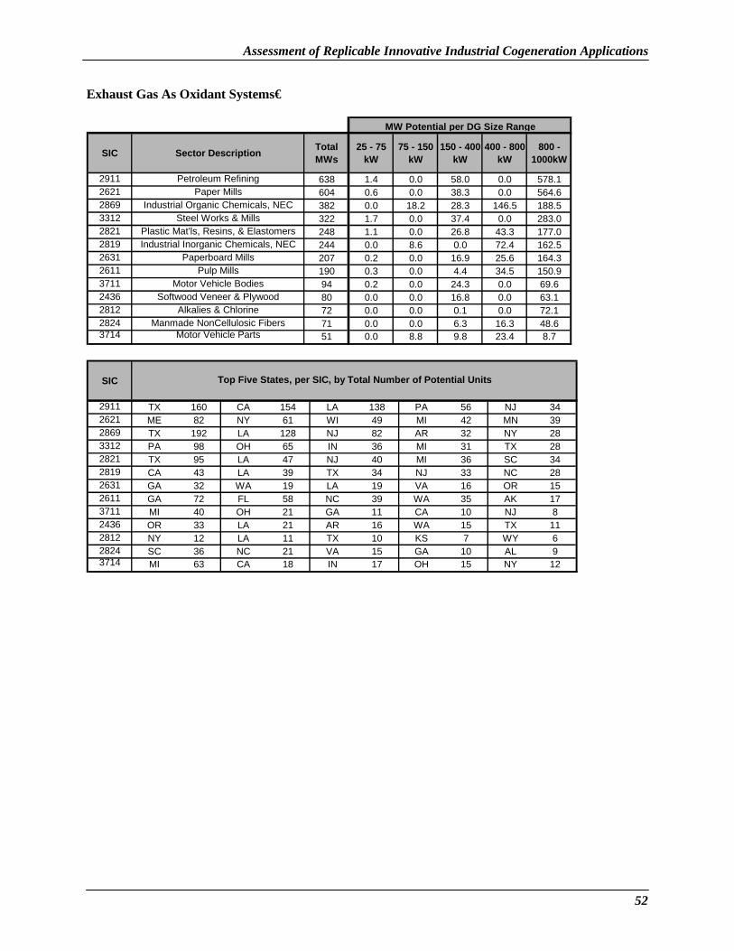
Assessment of Replicable Innovative Industrial Cogeneration Applications
Exhaust Gas As Oxidant Systems�
SIC Sector Description Total MWs
25 - 75 kW
75 - 150 kW
150 - 400 kW
400 - 800 kW
800 -1000kW
2911 Petroleum Refining 638 1.4 0.0 58.0 0.0 578.1 2621 Paper Mills 604 0.6 0.0 38.3 0.0 564.6 2869 Industrial Organic Chemicals, NEC 382 0.0 18.2 28.3 146.5 188.5 3312 Steel Works & Mills 322 1.7 0.0 37.4 0.0 283.0 2821 Plastic Mat'ls, Resins, & Elastomers 248 1.1 0.0 26.8 43.3 177.0 2819 Industrial Inorganic Chemicals, NEC 244 0.0 8.6 0.0 72.4 162.5 2631 Paperboard Mills 207 0.2 0.0 16.9 25.6 164.3 2611 Pulp Mills 190 0.3 0.0 4.4 34.5 150.9 3711 Motor Vehicle Bodies 94 0.2 0.0 24.3 0.0 69.6 2436 Softwood Veneer & Plywood 80 0.0 0.0 16.8 0.0 63.1 2812 Alkalies & Chlorine 72 0.0 0.0 0.1 0.0 72.1 2824 Manmade NonCellulosic Fibers 71 0.0 0.0 6.3 16.3 48.6 3714 Motor Vehicle Parts 51 0.0 8.8 9.8 23.4 8.7
MW Potential per DG Size Range
SIC Top Five States, per SIC, by Total Number of Potential Units
2911 TX 160 CA 154 LA 138 PA 56 NJ 34 2621 ME 82 NY 61 WI 49 MI 42 MN 39 2869 TX 192 LA 128 NJ 82 AR 32 NY 28 3312 PA 98 OH 65 IN 36 MI 31 TX 28 2821 TX 95 LA 47 NJ 40 MI 36 SC 34 2819 CA 43 LA 39 TX 34 NJ 33 NC 28 2631 GA 32 WA 19 LA 19 VA 16 OR 15 2611 GA 72 FL 58 NC 39 WA 35 AK 17 3711 MI 40 OH 21 GA 11 CA 10 NJ 8 2436 OR 33 LA 21 AR 16 WA 15 TX 11 2812 NY 12 LA 11 TX 10 KS 7 WY 6 2824 SC 36 NC 21 VA 15 GA 10 AL 9 3714 MI 63 CA 18 IN 17 OH 15 NY 12
52

Assessment of Replicable Innovative Industrial Cogeneration Applications
Sensitivity Analysis Installed costs for the innovative cogeneration equipment decrease in terms of dollars per kW as the equipment size increases. This is because packaged reciprocating engine and turbines prices, thermal system retrofit, engineering, and installation costs decrease in terms of dollars per kW as the equipment size increase. As an example, the installed cost for the 25-75 kW indirect air heating system using a recuperated turbine is $1,641/kW, but in the 800-1000 kW size range is only $836/kW.
Thermal system retrofit, engineering, and installation cost were determined by specifying a base case for the smallest size range, and then using a multiplier to estimate costs for larger size ranges. The equation takes the following form: cost multiplier (absolute $) = (size multiplier)^n, where n is between 0.20 to 0.60. A sensitivity analysis was performed using n = 0.75 for retrofit, engineering, and installation. This lead to a smaller decrease in installed cost as the equipment size increased. For example, the 25-75 kW indirect air heating system using a recuperated turbine is $1,641/kW, but in this sensitivity analysis now decrease to $1,043/kW in the 800-1000 kW size range (instead of $836/kW). The following tables show the results using this less aggressive installed cost reduction scenario.
Table 17. Less Aggressive Installed Cost Reduction - System Type
Cogeneration Package Systems Economic Market Potential (MWe) Direct Contact Water Heater 1,741 Indirect Liquid Heaters 835 Convection Ovens for Metal Fabrication Preheating
648
Indirect Air Heating 1,865 Oxidant for Central Boiler Systems 2,865 Total 7,954
The 10 states showing the highest economic market potential are (sensitivity analysis):
Table 18. Less Aggressive Installed Cost Reduction - State
State Economic Market Potential (MWe) California 1,649 New Jersey 607 New York 486 Texas 440 Michigan 419 Pennsylvania 383 Ohio 338 Louisiana 278 Wisconsin 258 Georgia 224 Other States 2,873 Total 7,954
53

Assessment of Replicable Innovative Industrial Cogeneration Applications
Economic market potential broken down by prime mover size range is (sensitivity analysis):
Table 19. Less Aggressive Installed Cost Reduction - Size Range
Size Range Economic Market Potential (MWe) 25-75 kW 149 75-150 kW 439 150-400 kW 1,193 400-800 kW 1,280 800-1000 kW 4,893 Total 7,954
Economic market potential broken down by prime mover type is (sensitivity analysis):
Table 20. Less Aggressive Installed Cost Reduction - Prime Mover
Prime Mover Type Economic Market Potential (MWe) Recuperated Turbines 478 Unrecuperated Turbines 4,023 Reciprocating Engines 3,454 Total 7,954
54

Assessment of Replicable Innovative Industrial Cogeneration Applications
Conclusions This assessment shows there is a potentially significant market for small innovative industrial cogeneration technologies. These units can beat conventional solutions in: • Applications where the thermal systems retrofit cost is low, • Larger sizes applications, because retrofit, engineering, and installation costs are lower in terms of $
per kW than in the smaller sizes, • Applications where most or all of the waste heat is being used, • Applications where the existing thermal system efficiency is low, and • Applications in areas with high electric rates.
Lowering the installed cost for the smaller size ranges (especially installation and retrofit) would increase the market potential even further.
Benefits Innovative industrial cogeneration systems can help industrial end users reduce air emissions, lower costs, and make their plants more competitive. This study examined retrofit opportunities, but economic benefits to end users would likely be greater if innovative cogeneration solutions were adopted in plants with failed thermal equipment that needed to be replaced anyway.
From a national perspective, innovative industrial cogeneration solutions will provide the following benefits: • Increased overall system efficiency for some processes in the industrial sector, • Reduced air emissions, • A more competitive industrial base, and • Reduced demand on the electricity grid.
This report gives important information to cogeneration project developers and technology funders such as the U.S. Department of Energy on the overall magnitude of the market and also provides critical data on the top application types, size ranges, and states.
Barriers The results shown in this assessment show the economic market potential. There are a number of barriers that may limit applications of these technologies. Some of these barriers may be regional in nature. The barriers include:
• Product performance and availability, • Lack of off-the-shelf integrated systems, • Presence of a supporting market infrastructure, • Awareness, information and education of end users, • Demonstration of successful case studies, • Environmental regulations, • Planning, zoning, and codes, and • Tax treatment.
There clearly exists a need for a structured approach to assist with the development and deployment of innovative cogeneration systems in the industrial sector. This approach needs to foster the development of industrial cooling and heating systems that can easily be integrated with distributed generation
55

Assessment of Replicable Innovative Industrial Cogeneration Applications
equipment. The approach should demonstrate these systems in industrial settings and then develop case studies around these demonstrations. These case studies need to include validated and verified data on the systems’ operation and performance. In addition, the structured approach also needs to address the potential barriers and how to overcome them.
Acknowledgement: The report was supported by the Industrial Center Distributed Generation Consortium and the Oak Ridge National Laboratory/U.S. Department of Energy Office of Power Technologies’ Distributed Energy Resources Program, and was developed for the Industrial Center, Inc. by Resource Dynamics Corporation and CSGI, Inc.
56