iter progress in pictures · iter progress in pictures june 2014. 01 iter ... capturing the fire of...
TRANSCRIPT

ITERPROGRESS IN PICTURESJune 2014

01
ITERPROGRESS IN PICTURES
June 2014

02
A star will be born
A new star will soon be born, a star unlike any other… a man-made star. ITER – theLatin word for “The Way” – will light up in the early years of the coming decade.From a scientific and technological point of view, it will be one of humankind’shistoric achievements. The creation of an artificial star and the tapping of thetremendous amounts of energy produced could forever alter the course of civilization.
The ITER Project, an unprecedented international collaboration that brings togetherChina, the European Union, India, Japan, Korea, Russia and the United States, is theculmination of decades of research and years of diplomatic negotiation. What wasthe aspiration of three generations of physicists is now the reality of the hundreds ofscientists, engineers and labourers working in southern France where the ITERinstallation is under construction.
The seven ITER Members, representing half the world’s population, share theresponsibility for building the ITER machine and facilities. Every Member, essentially,is involved in every system.
As buildings rise on the ITER platform (part of European procurement, pages 4 to15),component manufacturing advances in ITER Member factories (pages 21 to 41).
This booklet aims to take you into the heart of ITER, from the rolling hills ofProvence to factories on three continents, where men and women from 35 nationsare bent on realizing one of mankind’s most enduring dreams: capturing the fire ofthe stars and making it available to humanity for the millennia to come.
03
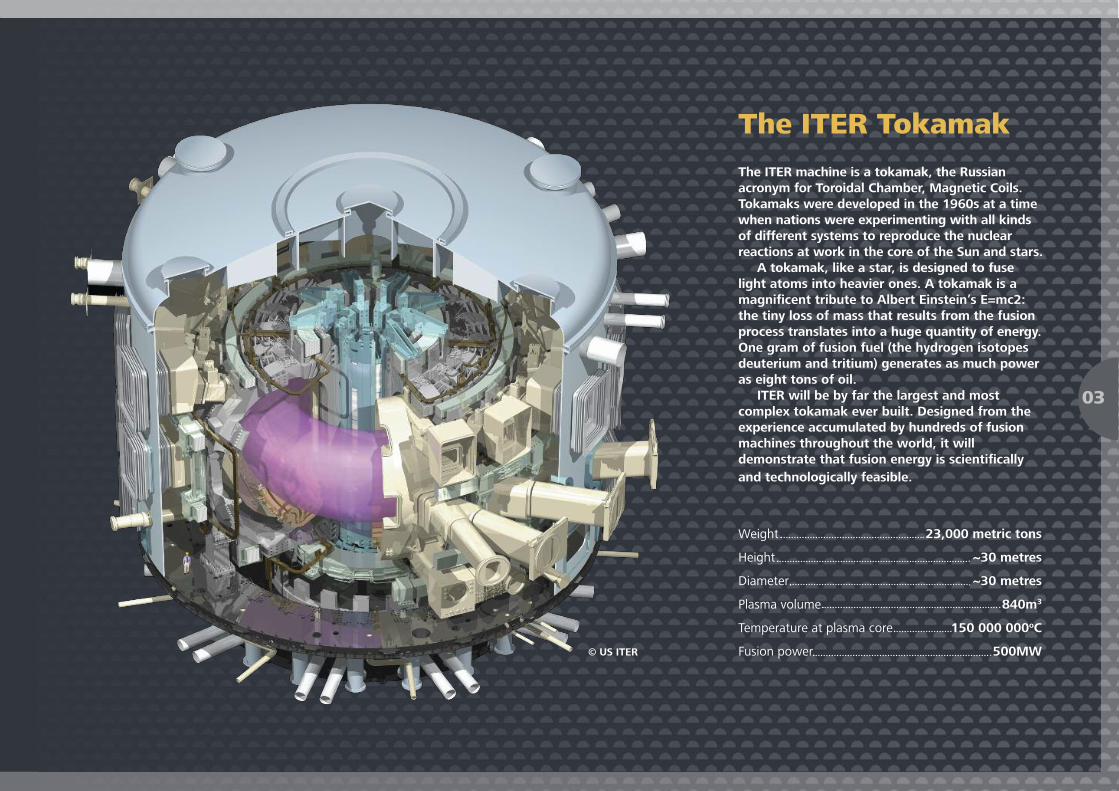
The ITER TokamakThe ITER machine is a tokamak, the Russianacronym for Toroidal Chamber, Magnetic Coils.Tokamaks were developed in the 1960s at a timewhen nations were experimenting with all kindsof different systems to reproduce the nuclearreactions at work in the core of the Sun and stars.
A tokamak, like a star, is designed to fuselight atoms into heavier ones. A tokamak is amagnificent tribute to Albert Einstein’s E=mc2:the tiny loss of mass that results from the fusionprocess translates into a huge quantity of energy.One gram of fusion fuel (the hydrogen isotopesdeuterium and tritium) generates as much poweras eight tons of oil.
ITER will be by far the largest and mostcomplex tokamak ever built. Designed from theexperience accumulated by hundreds of fusionmachines throughout the world, it willdemonstrate that fusion energy is scientificallyand technologically feasible.
Weight 23,000 metric tons
Height ~30 metres
Diameter ~30 metres
Plasma volume 840m3
Temperature at plasma core 150 000 000oC
Fusion power 500MW© US ITER
Site map
04
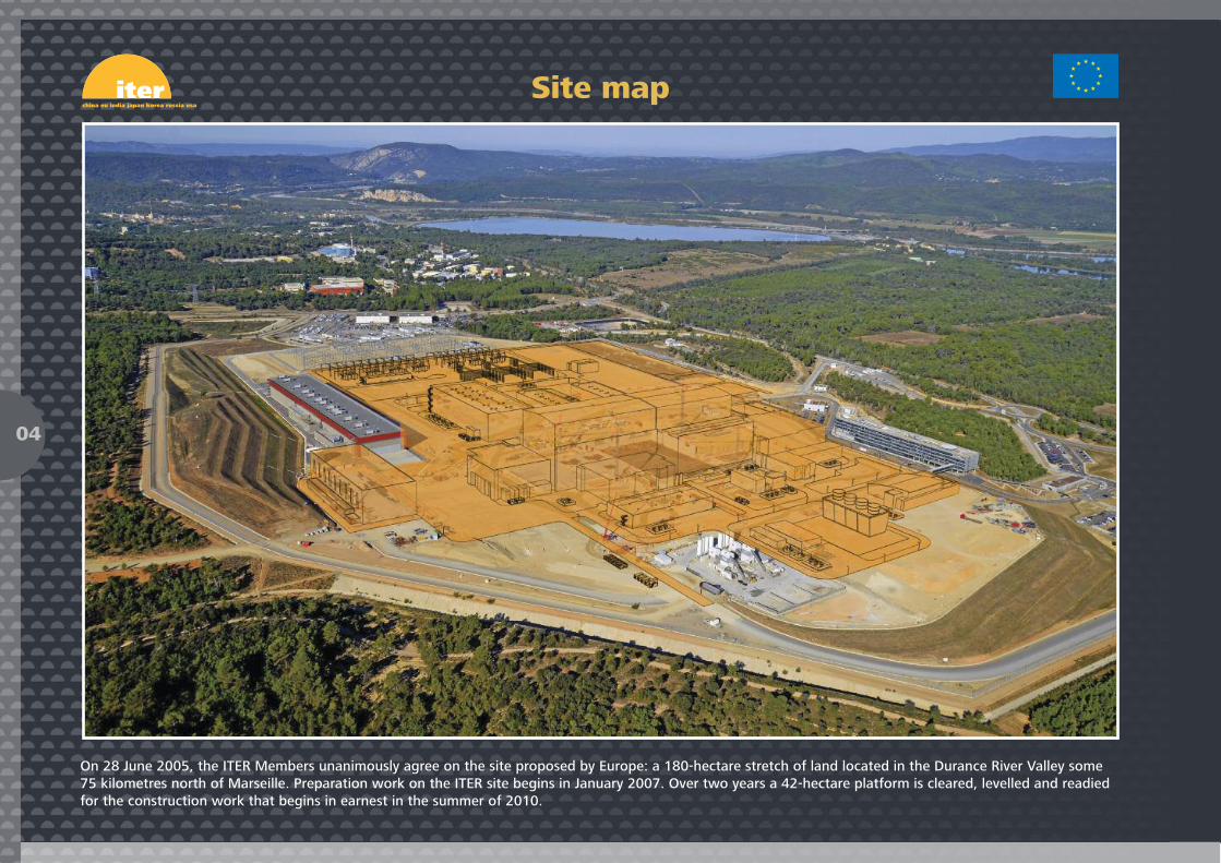
On 28 June 2005, the ITER Members unanimously agree on the site proposed by Europe: a 180-hectare stretch of land located in the Durance River Valley some75 kilometres north of Marseille. Preparation work on the ITER site begins in January 2007. Over two years a 42-hectare platform is cleared, levelled and readiedfor the construction work that begins in earnest in the summer of 2010.

Looking north over the ITER worksite. April 2014
The ITER site, looking north
05
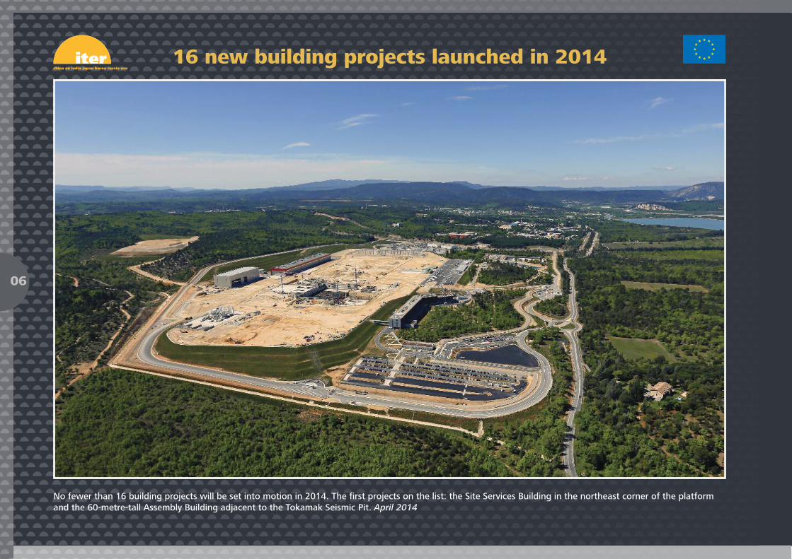
No fewer than 16 building projects will be set into motion in 2014. The first projects on the list: the Site Services Building in the northeast corner of the platformand the 60-metre-tall Assembly Building adjacent to the Tokamak Seismic Pit. April 2014
16 new building projects launched in 2014
06

The heart of activity: the Tokamak Seismic Pit (centre left), the Assembly Building worksite (centre right) and the ITER Headquarters (background). June 2014
Work in progress, June 2014
07

The three buildings of the Tokamak Complex will share a common foundation. In case of a seismic event, 493 steel and rubber seismic pads will absorb ground motionand preserve the integrity and safety of the installation. July 2012
The Tokamak Pit seismic protection system
08

The antiseismic columns and pads are hidden from view by the formwork and reinforcement underway for the next-level basemat. The B2 slab will support the400,000-ton Tokamak Complex. September 2013
Tokamak Complex slab preparation
09

The Diagnostics Building will be situated at one end of the Seismic Pit. Work begins to pour the first of three basemat segments before dawn on 11 December 2013;the Diagnostics Building slab is completed in February 2014.
First concrete for the Diagnostics Building
10

Concrete pouring for the Tritium Building slab (opposite the Diagnostics Building) begins on 19 March 2014. Nearly 1,000 m³ of concrete are employed to fill a 638 m²plot in the northeast corner of the Seismic Pit. March 2014
First concrete for the Tritium Building
11
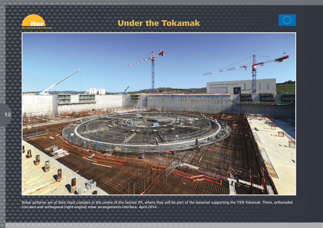
Rebar patterns are at their most complex in the centre of the Seismic Pit, where they will be part of the basemat supporting the ITER Tokamak. There, orthoradial(circular) and orthogonal (right-angled) rebar arrangements interface. April 2014
Under the Tokamak
12

The Tokamak Complex is a suite of three buildings on a common foundation. On the left, the finished basemat slab of the Diagnostics Building. On the right, pouringis underway on the Tritium Building slab. In the central area, the circular pattern of rebar that will support the machine. April 2014
The Seismic Pit from above
13
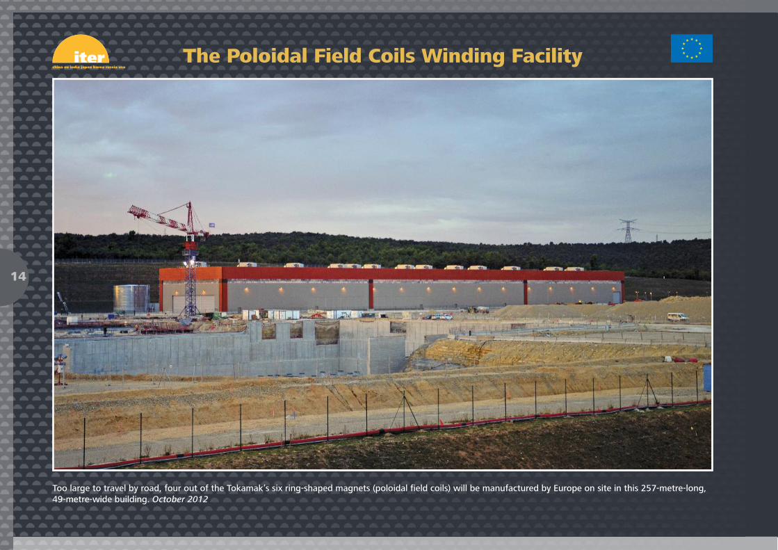
Too large to travel by road, four out of the Tokamak’s six ring-shaped magnets (poloidal field coils) will be manufactured by Europe on site in this 257-metre-long,49-metre-wide building. October 2012
The Poloidal Field Coils Winding Facility
14

Inside the Poloidal Field Coils Winding Facility, this large, sun-like, spreader beam will permit the very careful and steady transport of the poloidal field coils duringthe winding and assembly process. It will handle loads up to 50 tons.
A Sun-like spreader beam
15
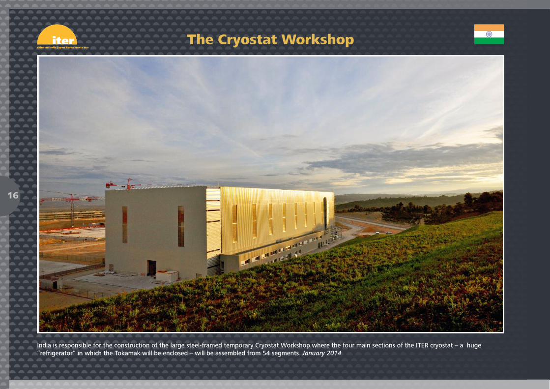
India is responsible for the construction of the large steel-framed temporary Cryostat Workshop where the four main sections of the ITER cryostat – a huge“refrigerator” in which the Tokamak will be enclosed – will be assembled from 54 segments. January 2014
The Cryostat Workshop
16

The first elements of the Cryostat Workshop gantry crane are delivered on site. With a lifting capacity of 200 tons (plus an auxiliary 50-ton hook) the crane will beused to lift and handle the 54 cryostat segments that will arrive from India. February 2014
Installation of the Cryostat Workshop crane
17

18
Pre-machining is performed on Europe’s first series production radial plate at CNIM, France. May 2014
19
Manufacturing
Aunique aspect of ITER implementation is the in-kindprocurement system that was established at theonset of the project. Instead of contributing
purely financial resources, China, the European Union,India, Japan, Korea, Russia and the United States will beproviding 90% of their contributions in the form ofmachine components, systems and – in the case ofEurope – buildings.
Procurement packages are shared equally (~ 9% of the totalvalue) between China, India, Japan, Korea, Russia and theUnited States; Europe’s share, as Host Member, is ~ 45%.
The in-kind procurement process forms the core of ITERfounding philosophy, offering the ITER Members invaluableexperience in the manufacturing of components for a fusioninstallation. By contributing to the construction of theexperimental machine, the ITER Members are creating thetechnological and industrial basis for the commercial fusionreactors of the future.

Who manufactures what?
20
Cryostat
Vacuum Vessel
Blanket
Feeders (31)
Toroidal Field Coils (18)
Poloidal Field Coils (6)
Divertor
Cooling Water System
Page 22 Page 16, 17, 27
Page 34
Page 24, 28, 33, 35, 38
Page 37
Page 40
Page 25, 30, 31, 32, 36
Page 14, 15, 21, 36
Page 23
Page 31, 39Not all systems and contributions are represented in this illustration.
Pellet Injection & Disruption Mitigation
Page 41
Correction Coils (18)
Central Solenoid (6)
Thermal Shield

The ITER magnet system requires close to 2,800 metric tons of superconducting coils. Before launching actual fabrication, prototypes and “dummies” need to beproduced. Here, China delivers a first batch of dummy conductor to the Poloidal Field Coil Winding Facility for fabrication process testing. June 2013
China delivers dummy conductor
21

For the magnet feeders, which bring electrical power and cryogens to the magnets, coil terminal boxes provide housing for the connections of the system.Machining was completed by Shanghai Aerospace Equipment in China for the first of 31 boxes in April 2014. The first box is now undergoing integral testing atthe Institute of Plasma Physics, Chinese Academy of Sciences (ASIPP).
Magnet feeders
22
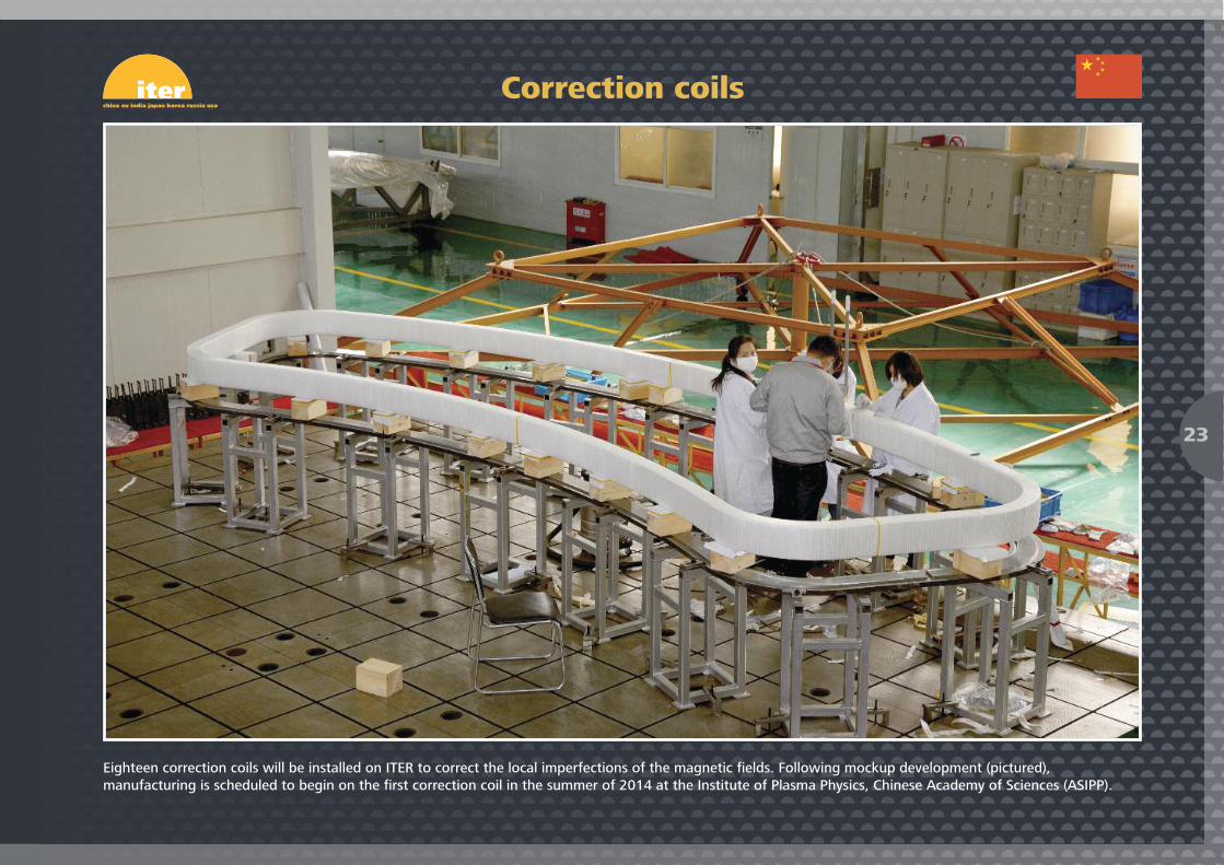
Eighteen correction coils will be installed on ITER to correct the local imperfections of the magnetic fields. Following mockup development (pictured),manufacturing is scheduled to begin on the first correction coil in the summer of 2014 at the Institute of Plasma Physics, Chinese Academy of Sciences (ASIPP).
Correction coils
23
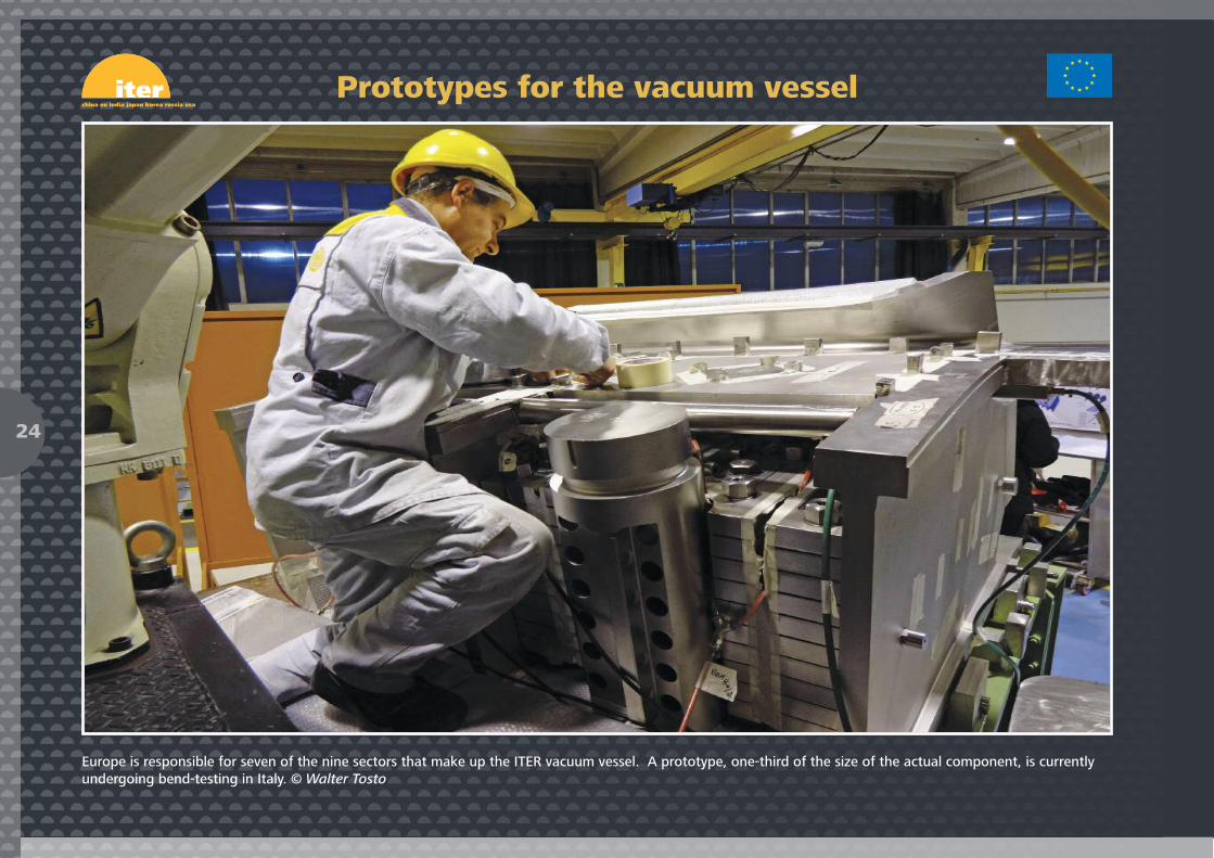
Europe is responsible for seven of the nine sectors that make up the ITER vacuum vessel. A prototype, one-third of the size of the actual component, is currentlyundergoing bend-testing in Italy. © Walter Tosto
Prototypes for the vacuum vessel
24
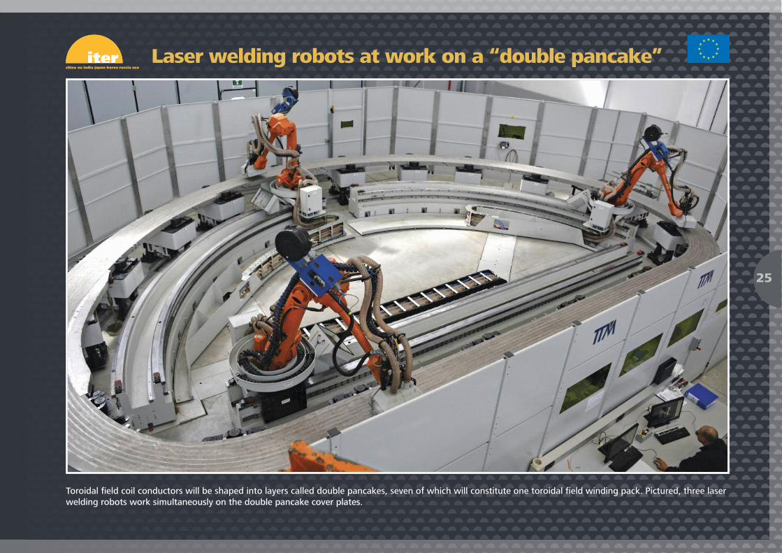
Toroidal field coil conductors will be shaped into layers called double pancakes, seven of which will constitute one toroidal field winding pack. Pictured, three laserwelding robots work simultaneously on the double pancake cover plates.
Laser welding robots at work on a “double pancake”
25
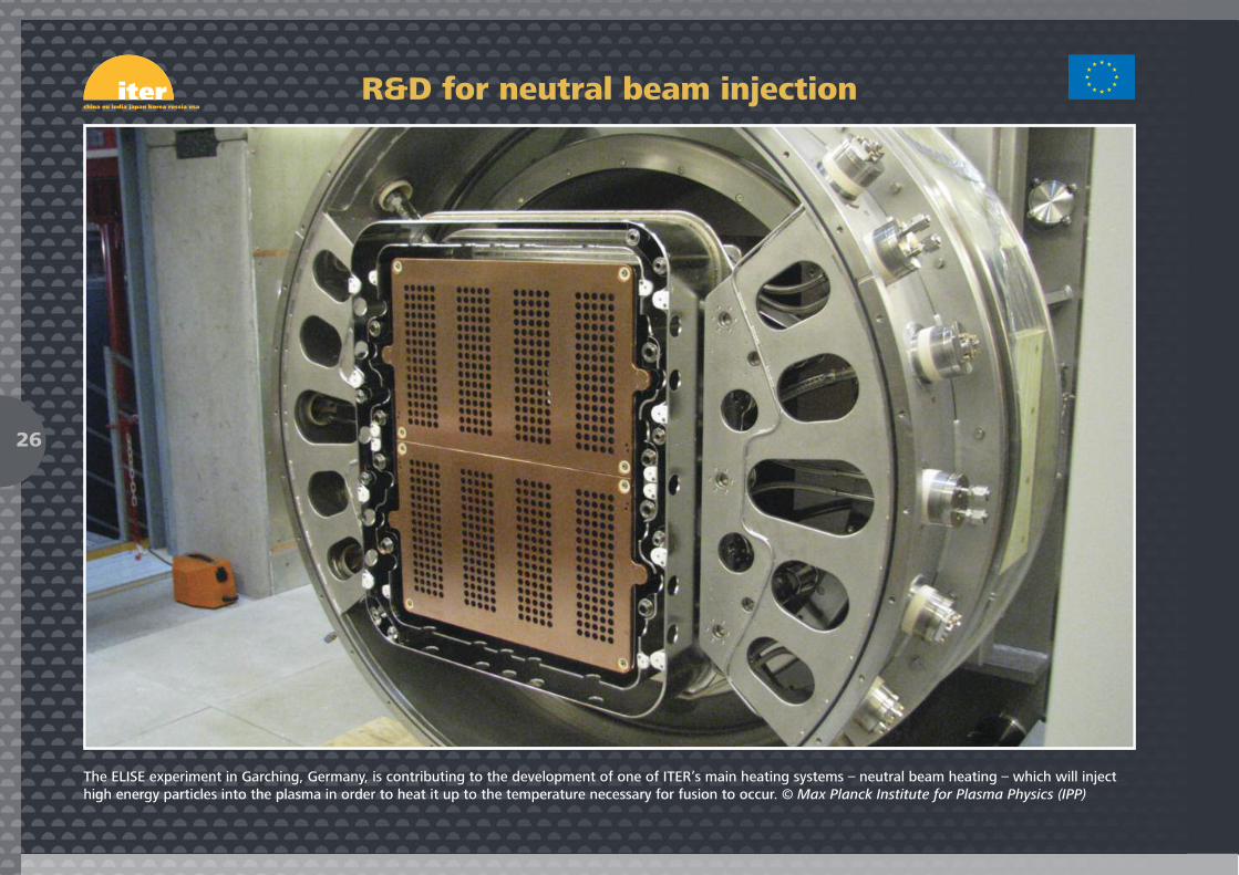
The ELISE experiment in Garching, Germany, is contributing to the development of one of ITER’s main heating systems – neutral beam heating – which will injecthigh energy particles into the plasma in order to heat it up to the temperature necessary for fusion to occur. © Max Planck Institute for Plasma Physics (IPP)
R&D for neutral beam injection
26
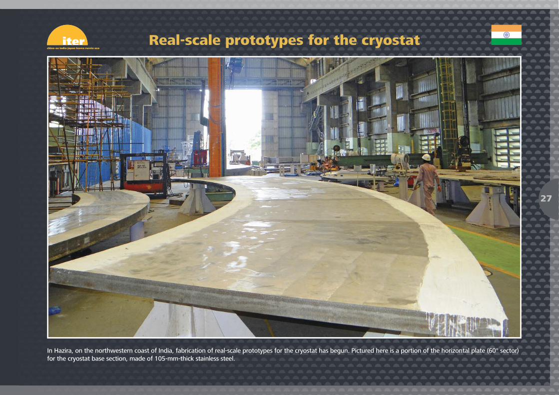
In Hazira, on the northwestern coast of India, fabrication of real-scale prototypes for the cryostat has begun. Pictured here is a portion of the horizontal plate (60° sector)for the cryostat base section, made of 105-mm-thick stainless steel.
Real-scale prototypes for the cryostat
27

This in-wall shielding block assembly (600 mm long, 180 mm wide and 140 mm high) will be installed in the vacuum vessel. India will produce approximately 8,000such components of different types and sizes and send them to Europe and Korea for further assembly into the vacuum vessel sectors.
8,000 in-wall shielding components
28
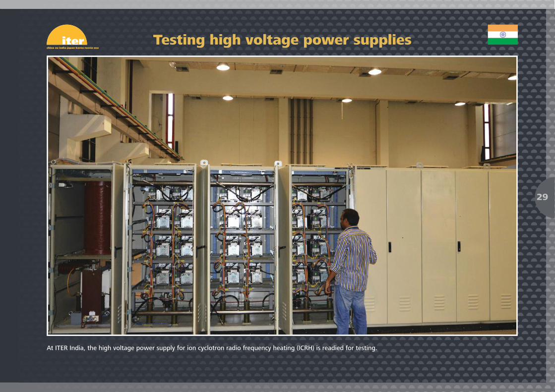
At ITER India, the high voltage power supply for ion cyclotron radio frequency heating (ICRH) is readied for testing.
Testing high voltage power supplies
29

Upon the completion of jacketing, 760-metre-long toroidal field conductor unit lengths are spooled to facilitate transportation. In the image, three unit lengths areprepared for transport at the Wakamatsu factory, Nippon Steel & Sumikin Engineering.
Spooling toroidal field conductor
30

The superconducting strands in the ITER central solenoid and toroidal field coils are made of niobium-tin alloy. At JASTEC’s Moji factory, workers prepare 40- to 100-kg“billets” that will eventually be transformed into millimetre-thin strands.
From billets to strands
31
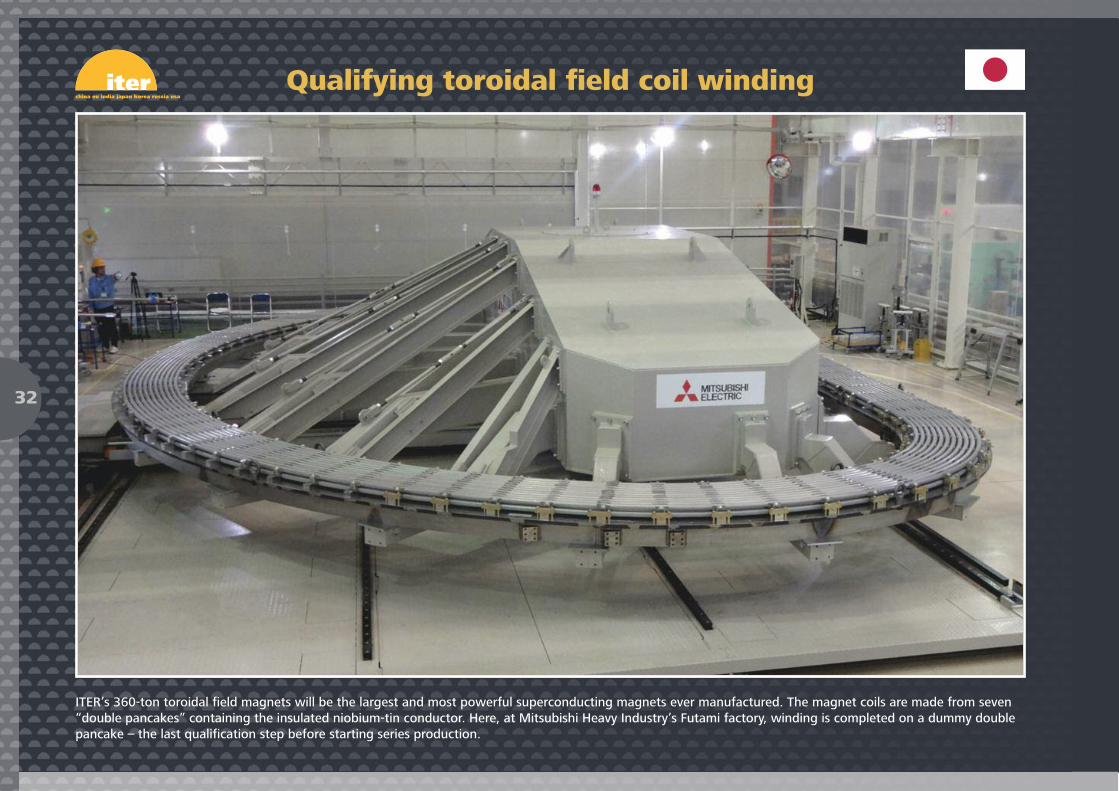
ITER’s 360-ton toroidal field magnets will be the largest and most powerful superconducting magnets ever manufactured. The magnet coils are made from seven“double pancakes” containing the insulated niobium-tin conductor. Here, at Mitsubishi Heavy Industry’s Futami factory, winding is completed on a dummy doublepancake – the last qualification step before starting series production.
Qualifying toroidal field coil winding
32
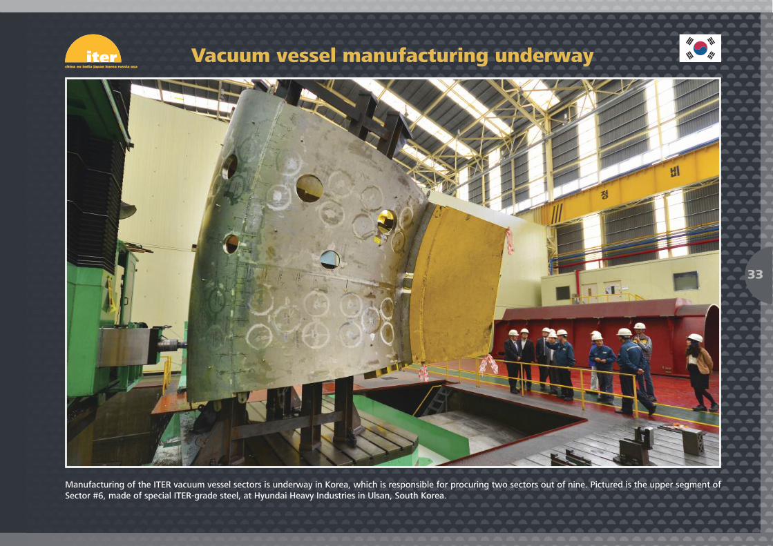
Manufacturing of the ITER vacuum vessel sectors is underway in Korea, which is responsible for procuring two sectors out of nine. Pictured is the upper segment ofSector #6, made of special ITER-grade steel, at Hyundai Heavy Industries in Ulsan, South Korea.
Vacuum vessel manufacturing underway
33
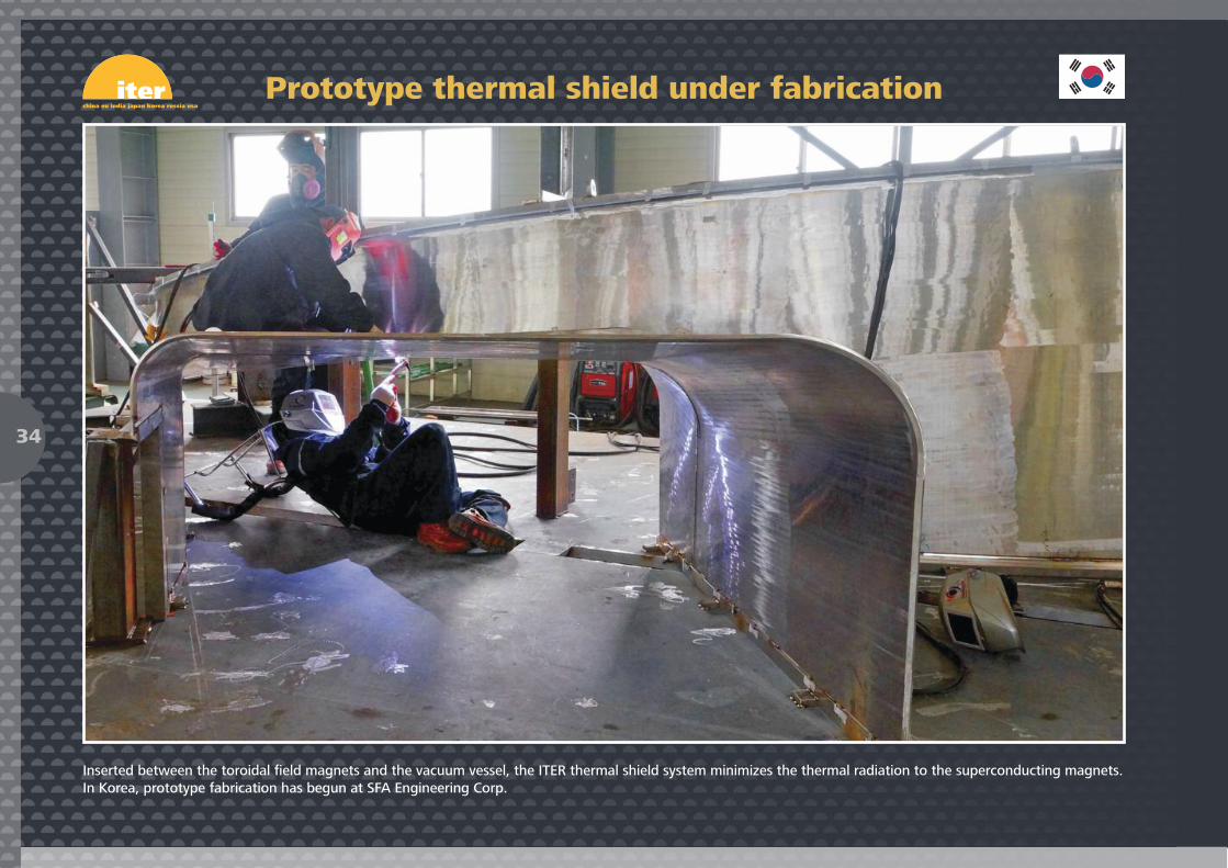
Inserted between the toroidal field magnets and the vacuum vessel, the ITER thermal shield system minimizes the thermal radiation to the superconducting magnets.In Korea, prototype fabrication has begun at SFA Engineering Corp.
Prototype thermal shield under fabrication
34
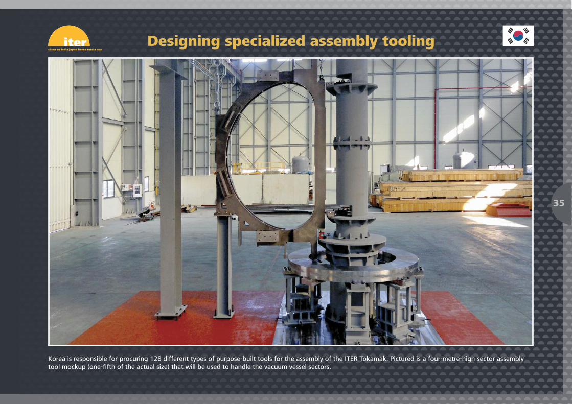
Korea is responsible for procuring 128 different types of purpose-built tools for the assembly of the ITER Tokamak. Pictured is a four-metre-high sector assemblytool mockup (one-fifth of the actual size) that will be used to handle the vacuum vessel sectors.
Designing specialized assembly tooling
35

The Chepetsky Mechanical Plant (Glazov, Udmurtia) provides Russian conductor manufacturers with superconducting strands for the cabling, jacketing and spoolingof toroidal field and poloidal field conductors.
A strand manufacturing facility
36
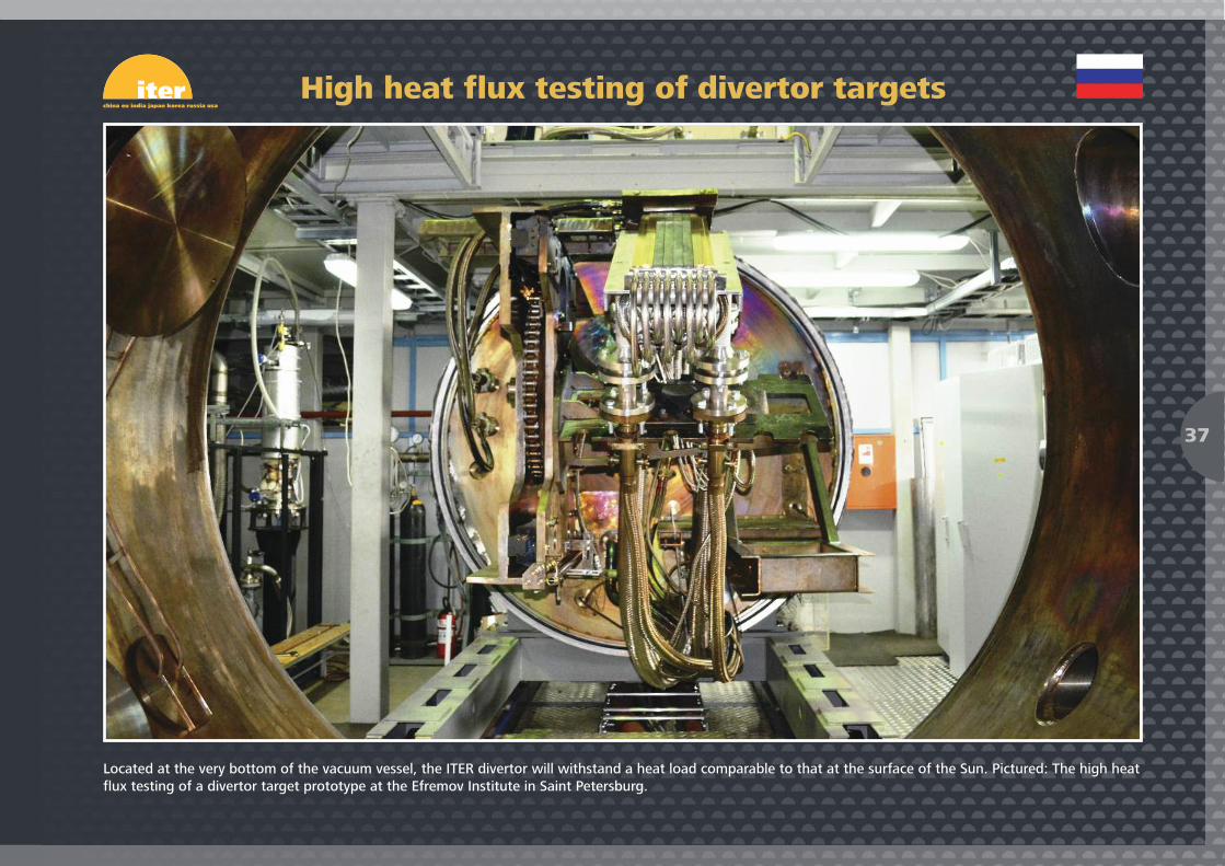
Located at the very bottom of the vacuum vessel, the ITER divertor will withstand a heat load comparable to that at the surface of the Sun. Pictured: The high heatflux testing of a divertor target prototype at the Efremov Institute in Saint Petersburg.
High heat flux testing of divertor targets
37

In early April, Cryogenmash (near Moscow, Russia) starts a series of gasket tests for the ITER Port Plug Test Facility, where port plugs – the large, leak-tight stainlesssteel plugs that seal the vacuum vessel’s openings and that weigh up to 50 tons – will be submitted to vacuum, heat and functional testing prior to their installationin the machine.
Testing the port plugs
38
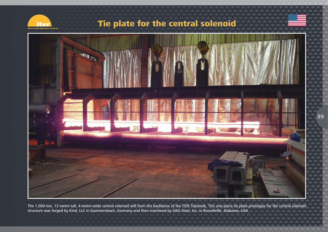
The 1,000-ton, 13 metre-tall, 4-metre-wide central solenoid will form the backbone of the ITER Tokamak. This one-piece tie plate prototype for the central solenoidstructure was forged by Kind, LLC in Gummersbach, Germany and then machined by G&G Steel, Inc. in Russellville, Alabama, USA.
Tie plate for the central solenoid
39
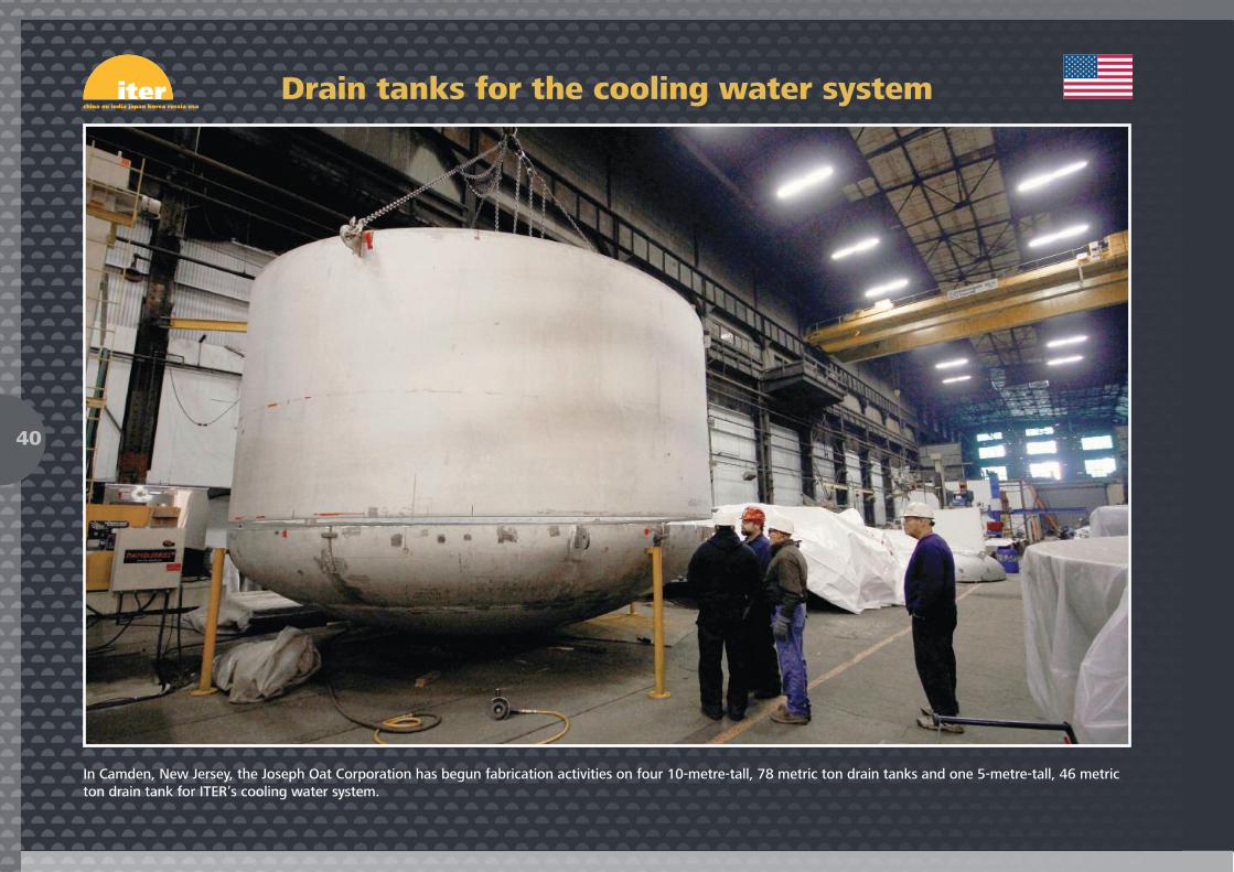
In Camden, New Jersey, the Joseph Oat Corporation has begun fabrication activities on four 10-metre-tall, 78 metric ton drain tanks and one 5-metre-tall, 46 metricton drain tank for ITER’s cooling water system.
Drain tanks for the cooling water system
40
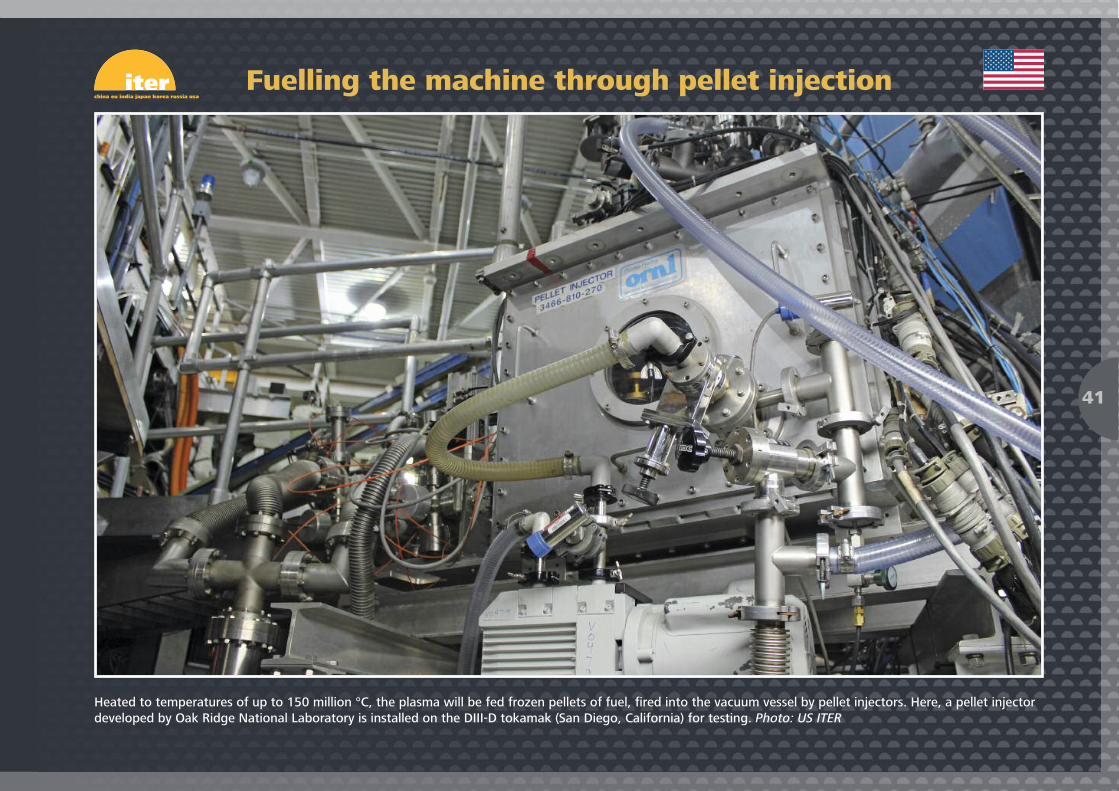
Heated to temperatures of up to 150 million °C, the plasma will be fed frozen pellets of fuel, fired into the vacuum vessel by pellet injectors. Here, a pellet injectordeveloped by Oak Ridge National Laboratory is installed on the DIII-D tokamak (San Diego, California) for testing. Photo: US ITER
Fuelling the machine through pellet injection
41
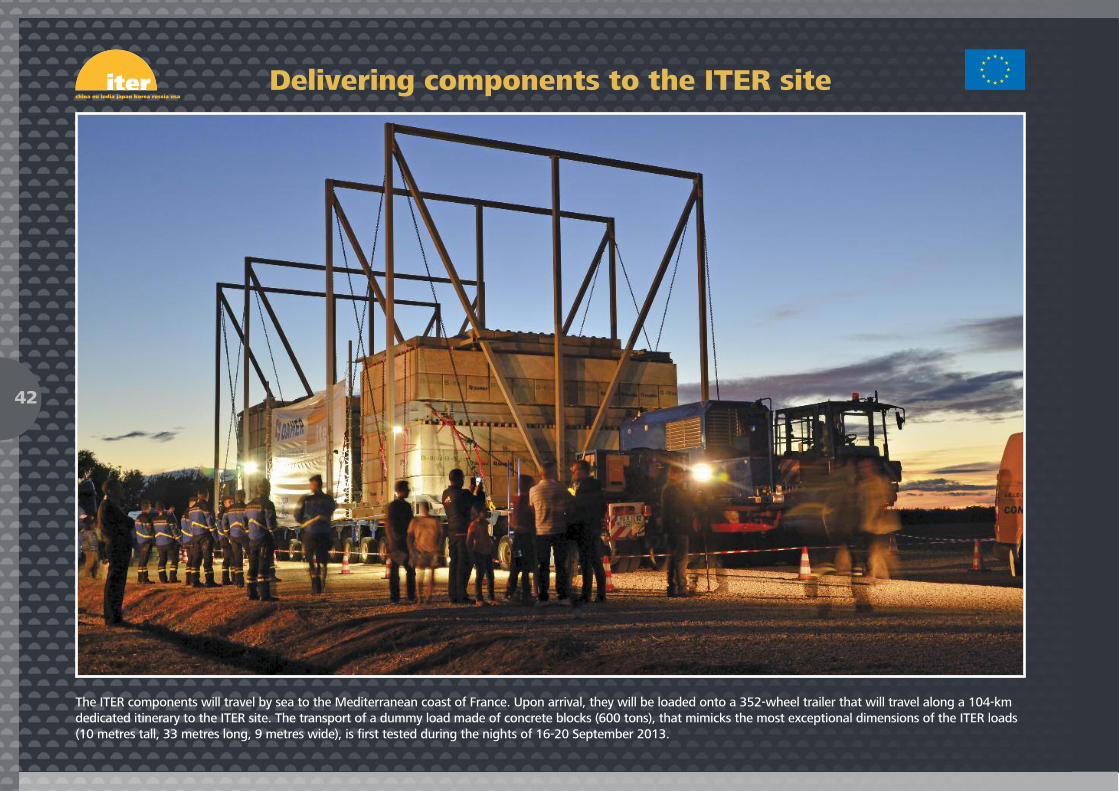
The ITER components will travel by sea to the Mediterranean coast of France. Upon arrival, they will be loaded onto a 352-wheel trailer that will travel along a 104-kmdedicated itinerary to the ITER site. The transport of a dummy load made of concrete blocks (600 tons), that mimicks the most exceptional dimensions of the ITER loads(10 metres tall, 33 metres long, 9 metres wide), is first tested during the nights of 16-20 September 2013.
Delivering components to the ITER site
42
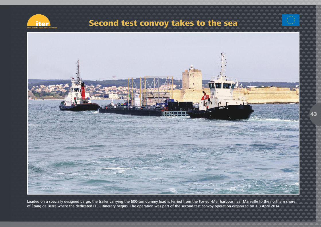
Loaded on a specially designed barge, the trailer carrying the 600-ton dummy load is ferried from the Fos-sur-Mer harbour near Marseille to the northern shoreof Étang de Berre where the dedicated ITER Itinerary begins. The operation was part of the second test convoy operation organized on 1-8 April 2014.
Second test convoy takes to the sea
43

In the early hours of Friday 8 April 2014, the second ITER Itinerary test convoy arrives successfully on site. This second week-long test, including the crossing of aninland sea by barge, is the last dry run before the transport of ITER components begins in earnest later this year.
An early arrival
44

Photo creditsCover ITER Organization, LESENECHAL/PPV-AIX.COM, ITER KoreaPages 04, 07 to 21, 33, 42 to 44 ITER OrganizationPages 05, 06 LESENECHAL/PPV-AIX.COM Pages 22, 23 ITER ChinaPage 24 Walter TostoPage 25 Fusion for EnergyPage 26 Max Planck Institute for Plasma PhysicsPages 27 to 29 ITER IndiaPage 30 JAEA - ITER JapanPage 31 JASTECPage 32 Mitsubishi Heavy Industries Ltd.Pages 34, 35 ITER KoreaPages 36 to 38 ITER RussiaPages 39 to 41 US ITERBack cover ITER Organization

ITER Organization HeadquartersRoute de Vinon-sur-Verdon CS 90 04613067 St. Paul-lez-Durance CedexFrance
© ITER Organization, June 2014
www.iter.org
Publications DirectorMichel [email protected]
EditorRobert [email protected]